Embed Size (px)
Citation preview

Design document
DaCoPAn2
Helsinki, 7th April 2005
Software Engineering Project
UNIVERSITY OF HELSINKIDepartment of Computer Science
Course581260-4 Software Engineering Project (6 cr)
Project GroupMikko AiraksinenTomi KorkkiPauli MiettinenTimo TuominenMikko Vaananen
CustomerMarkku Kojo
Project MastersJuha Taina (Supervisor)Marianne Korpela (Instructor)
Homepagehttp://www.cs.helsinki.fi/group/dacopan2
Change LogVersion Date Modifications1.0 March 17th 2005 First version2.0 March 29th 2005 Finished version
i
Contents
1 Introduction 1
2 Architecture 3
2.1 Data structure classes . . . . . . . . . . . . . . . . . . . . . . . . . . 3
2.2 Main UI . . . . . . . . . . . . . . . . . . . . . . . . . . . . . . . . . . 3
2.3 Animation panels . . . . . . . . . . . . . . . . . . . . . . . . . . . . . 4
2.4 Settings classes for animation . . . . . . . . . . . . . . . . . . . . . . 4
2.5 Panels for changing settings . . . . . . . . . . . . . . . . . . . . . . . 4
2.6 Control Signals framework . . . . . . . . . . . . . . . . . . . . . . . . 4
2.7 Buttons panel . . . . . . . . . . . . . . . . . . . . . . . . . . . . . . . 4
2.8 Animation Sequence framework . . . . . . . . . . . . . . . . . . . . . 5
2.9 Notes framework . . . . . . . . . . . . . . . . . . . . . . . . . . . . . 5
2.10 XML input/output . . . . . . . . . . . . . . . . . . . . . . . . . . . . 5
2.11 Localization . . . . . . . . . . . . . . . . . . . . . . . . . . . . . . . . 5
3 Data structures 5
3.1 Protocol data . . . . . . . . . . . . . . . . . . . . . . . . . . . . . . . 5
3.2 Host class . . . . . . . . . . . . . . . . . . . . . . . . . . . . . . . . . 7
3.3 Flow class . . . . . . . . . . . . . . . . . . . . . . . . . . . . . . . . . 7
3.4 Link class . . . . . . . . . . . . . . . . . . . . . . . . . . . . . . . . . 7
3.5 Protocol class . . . . . . . . . . . . . . . . . . . . . . . . . . . . . . . 7
3.6 Layer class . . . . . . . . . . . . . . . . . . . . . . . . . . . . . . . . . 8
3.7 VariableDefinition class . . . . . . . . . . . . . . . . . . . . . . . . . . 8
3.8 StaticVariable class . . . . . . . . . . . . . . . . . . . . . . . . . . . . 8
3.9 Notes . . . . . . . . . . . . . . . . . . . . . . . . . . . . . . . . . . . . 8
3.10 DataView interface . . . . . . . . . . . . . . . . . . . . . . . . . . . . 8
3.11 StepIterator interface . . . . . . . . . . . . . . . . . . . . . . . . . . . 10
4 Main User Interface design 10
4.1 General User Interface design . . . . . . . . . . . . . . . . . . . . . . 10
4.2 The functionality of the main UI classes . . . . . . . . . . . . . . . . 11
4.3 User actions . . . . . . . . . . . . . . . . . . . . . . . . . . . . . . . . 12
ii
5 Animation panels 14
5.1 Message Sequence Chart . . . . . . . . . . . . . . . . . . . . . . . . . 14
5.1.1 Columns . . . . . . . . . . . . . . . . . . . . . . . . . . . . . . 15
5.1.2 Drawing area . . . . . . . . . . . . . . . . . . . . . . . . . . . 15
5.1.3 Notes . . . . . . . . . . . . . . . . . . . . . . . . . . . . . . . 16
5.1.4 Improving the readability of the MSC . . . . . . . . . . . . . . 16
5.1.5 The CalcYCoord class . . . . . . . . . . . . . . . . . . . . . . 18
5.2 Encapsulation . . . . . . . . . . . . . . . . . . . . . . . . . . . . . . . 21
5.2.1 Note framework for ENC . . . . . . . . . . . . . . . . . . . . . 21
5.2.2 The ENC tree model . . . . . . . . . . . . . . . . . . . . . . . 21
5.2.3 General layout . . . . . . . . . . . . . . . . . . . . . . . . . . 21
5.3 Unit Flow Orchestration . . . . . . . . . . . . . . . . . . . . . . . . . 23
5.4 Time Sequence Chart . . . . . . . . . . . . . . . . . . . . . . . . . . . 24
5.4.1 Drawing area . . . . . . . . . . . . . . . . . . . . . . . . . . . 25
5.4.2 Legend . . . . . . . . . . . . . . . . . . . . . . . . . . . . . . . 27
5.4.3 Notes . . . . . . . . . . . . . . . . . . . . . . . . . . . . . . . 27
5.4.4 Notices . . . . . . . . . . . . . . . . . . . . . . . . . . . . . . . 27
5.4.5 Unit Info panel . . . . . . . . . . . . . . . . . . . . . . . . . . 28
6 Animation settings 28
6.1 Settings class structure . . . . . . . . . . . . . . . . . . . . . . . . . . 28
6.2 General settings . . . . . . . . . . . . . . . . . . . . . . . . . . . . . . 29
6.3 MSC settings . . . . . . . . . . . . . . . . . . . . . . . . . . . . . . . 29
6.3.1 SettingsMSC class . . . . . . . . . . . . . . . . . . . . . . . . 32
6.4 TSC Settings . . . . . . . . . . . . . . . . . . . . . . . . . . . . . . . 33
7 Control Signal framework 34
7.1 AnimationTimeState class . . . . . . . . . . . . . . . . . . . . . . . . 34
7.2 ControlSignalsListener interface . . . . . . . . . . . . . . . . . . . . . 35
8 Animation Sequence framework 36
8.1 AnimationSequence class . . . . . . . . . . . . . . . . . . . . . . . . . 36
8.2 ScenarioItem interface . . . . . . . . . . . . . . . . . . . . . . . . . . 37
8.3 ScenarioItemMSC class . . . . . . . . . . . . . . . . . . . . . . . . . . 37
iii
8.4 ScenarioItemTSC class . . . . . . . . . . . . . . . . . . . . . . . . . . 37
8.5 ScenarioItemENC class . . . . . . . . . . . . . . . . . . . . . . . . . . 37
8.6 ScenarioItemPause class . . . . . . . . . . . . . . . . . . . . . . . . . 38
8.7 Settings objects . . . . . . . . . . . . . . . . . . . . . . . . . . . . . . 38
8.8 ScenarioEditorDialog and ScenarioEditorPanel classes . . . . . . . . . 38
8.9 Recording an animation sequence . . . . . . . . . . . . . . . . . . . . 38
9 Notes framework 39
9.1 MSC Notes . . . . . . . . . . . . . . . . . . . . . . . . . . . . . . . . 40
9.2 ENC Notes . . . . . . . . . . . . . . . . . . . . . . . . . . . . . . . . 40
9.3 TSC Notes . . . . . . . . . . . . . . . . . . . . . . . . . . . . . . . . . 41
10 Protocol Events File reader 41
10.1 ProtocolEventsReader interface . . . . . . . . . . . . . . . . . . . . . 42
10.2 ProgressIndicator interface . . . . . . . . . . . . . . . . . . . . . . . . 43
10.3 XML protocol events reader . . . . . . . . . . . . . . . . . . . . . . . 43
10.3.1 XML support in Java 1.4 . . . . . . . . . . . . . . . . . . . . . 43
10.3.2 Implementation using the JAXP classes . . . . . . . . . . . . 44
10.4 PEF file enhancements . . . . . . . . . . . . . . . . . . . . . . . . . . 44
10.4.1 SACK . . . . . . . . . . . . . . . . . . . . . . . . . . . . . . . 44
10.4.2 Transfer unit size display . . . . . . . . . . . . . . . . . . . . . 44
11 Scenario data 45
11.1 Scenario file and settings . . . . . . . . . . . . . . . . . . . . . . . . . 45
11.2 Saving and loading the scenario data objects . . . . . . . . . . . . . . 46
11.3 Putting it altogether . . . . . . . . . . . . . . . . . . . . . . . . . . . 46
12 Localization 46
12.1 The Localization class . . . . . . . . . . . . . . . . . . . . . . . . . . 47
References 47
Appendices
A Glossary

iv
B Packet-level class diagrams
1
1 Introduction
The DaCoPAn Animator module enables the visualization of the packet trace in-formation provided by the DaCoPAn Analyzer module through the Protocol EventsFile (PEF). This DaCoPAn2 Animator Design Document is an updated documentbased on the existing DaCoPAn implementation and the original DaCoPAn Anima-tor Design Document [1]. It is a stand-alone document, which describes the entireAnimator software along with the changes that will be made to it by the DaCoPAn2project.
Section 2 presents the general architecture of the Animator module. An overviewdiagram will introduce us to the different elements of the Animator, explaining howthey are inter-related. A brief description of the elements can be found after thediagram. However, more precision on the different components follows in the nextsections.
Section 3 contains a description of the different data structures that hold the packettrace information given by the Analyzer module. These are accesible to the othercomponents in a suitable way. Data related to the scenario is also included in thedata structures (e.g. the Notes framework, see below).
Section 4 introduces the main user interface design. The different areas that theDaCoPAn Animator main window shows, their different features and the toolbarneeded to control them are presented. Java Swing package javax.swing is used forimplementation.
Section 5 presents the four different animation panels that the Animator shows.These are the Message Sequence Chart, Unit Flow Orchestration view, Encapsula-tion view, and Time Sequence Chart. It contains both diagrams and text descrip-tions on their disposition and behaviour.
Section 6 contains an explanation about the Animation setting classes.
Section 7 explains how the Control Signal framework is in charge of receiving com-mands from the user and timing events, and calling consequently the appropriateDaCoPAn Animator components, through its different classes and interfaces.
Section 8 contains the necessary information about the Animation Sequence frame-work, which is how the DaCoPAn Animator manages to present different presenta-tions sequentially.
Section 9 briefly presents how notes to be shown during different animation typesare handled by the Animator module. Notes are not a separate module, but areincluded in the network data model package as a part of the core data structures.
Section 10 illustrates how the Animator parses the packet trace information presentin the PEF (Protocol Event File) using existing XML libraries. Still, the PEF readerwon’t be tied to XML format for further developments of the DaCoPAn software.
Section 11 presents a way to save and load scenario data to and from a file, byrepresenting different settings and configurations made by the user and related to a

2
specific set of packet trace data (to a PEF, basically).
Section 12 describes the localization architecture of the Animator.
3
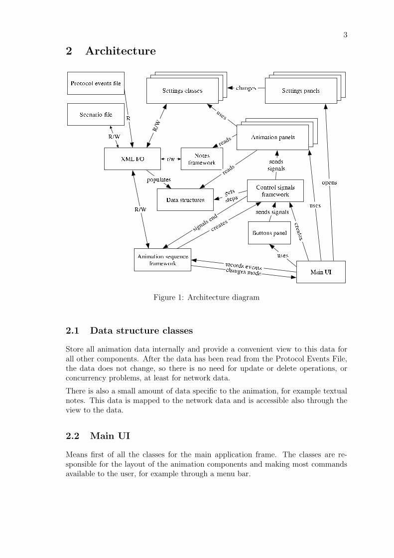
2 Architecture
Figure 1: Architecture diagram
2.1 Data structure classes
Store all animation data internally and provide a convenient view to this data forall other components. After the data has been read from the Protocol Events File,the data does not change, so there is no need for update or delete operations, orconcurrency problems, at least for network data.
There is also a small amount of data specific to the animation, for example textualnotes. This data is mapped to the network data and is accessible also through theview to the data.
2.2 Main UI
Means first of all the classes for the main application frame. The classes are re-sponsible for the layout of the animation components and making most commandsavailable to the user, for example through a menu bar.
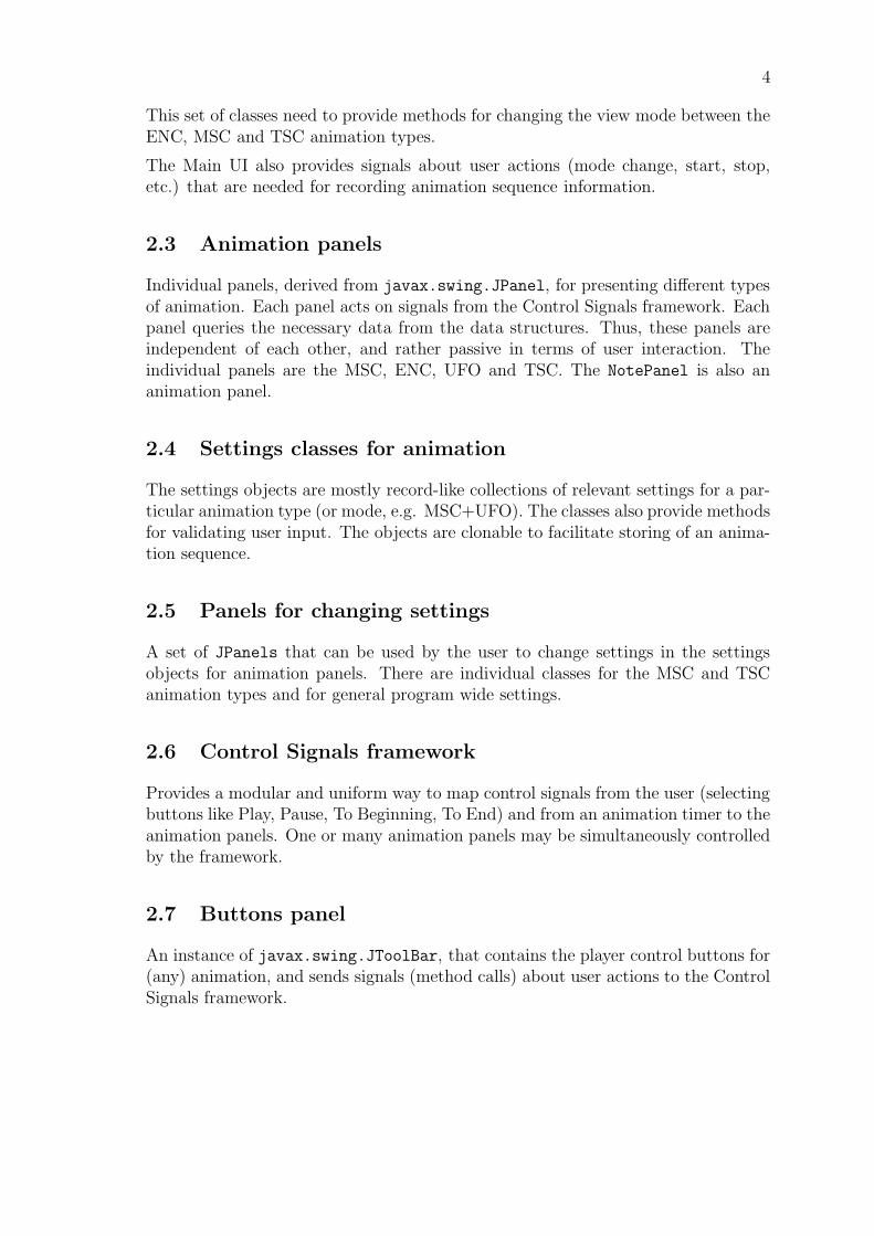
4
This set of classes need to provide methods for changing the view mode between theENC, MSC and TSC animation types.
The Main UI also provides signals about user actions (mode change, start, stop,etc.) that are needed for recording animation sequence information.
2.3 Animation panels
Individual panels, derived from javax.swing.JPanel, for presenting different typesof animation. Each panel acts on signals from the Control Signals framework. Eachpanel queries the necessary data from the data structures. Thus, these panels areindependent of each other, and rather passive in terms of user interaction. Theindividual panels are the MSC, ENC, UFO and TSC. The NotePanel is also ananimation panel.
2.4 Settings classes for animation
The settings objects are mostly record-like collections of relevant settings for a par-ticular animation type (or mode, e.g. MSC+UFO). The classes also provide methodsfor validating user input. The objects are clonable to facilitate storing of an anima-tion sequence.
2.5 Panels for changing settings
A set of JPanels that can be used by the user to change settings in the settingsobjects for animation panels. There are individual classes for the MSC and TSCanimation types and for general program wide settings.
2.6 Control Signals framework
Provides a modular and uniform way to map control signals from the user (selectingbuttons like Play, Pause, To Beginning, To End) and from an animation timer to theanimation panels. One or many animation panels may be simultaneously controlledby the framework.
2.7 Buttons panel
An instance of javax.swing.JToolBar, that contains the player control buttons for(any) animation, and sends signals (method calls) about user actions to the ControlSignals framework.
5
2.8 Animation Sequence framework
Is able to record and store a sequence of different presentation types (e.g. MSCanimation, ENC animation, TSC animation). Recording is done by collecting rel-evant user actions from the main UI and storing the necessary settings objects.The Control Signals framework signals the end of one presentation type from theAnimationTimeState class so that the Animation Sequence framework can makeactions to start the next presentation type. The format for storing the sequence isa playlist-type list of different presentations, that can also be presented to the useras a “playlist”. The user can jump to any item in the playlist and thus allow usingthe list as a crude “table of contents” for a scenario.
2.9 Notes framework
The notes framework is part of the network data model classes. It includes the Noteand NoteManager classes, and is described in more detail in section 9.
2.10 XML input/output
Takes care of reading in the Protocol Events File from the Analyzer and populatingthe data structures with network data as well as saving user edited scenarios. Con-sists of the ProtocolEventsReader interface which handles the input from PEFfiles, and the Scenario package which handles the serialization of the Scenario data.
2.11 Localization
Means a way storing all localizable resources (mostly strings) in one place wherethey can all be edited in one place. The mechanism makes it possible to retrievelocalizable resources according to the locale in use. The mechanism also allowsplacing placeholders (for variables) inside strings. The basic mechanism for this isalready provided by a standard Java class, java.util.ResourceBundle, which isused by Localization, an intermediate class for accessing the localized texts.
3 Data structures
3.1 Protocol data
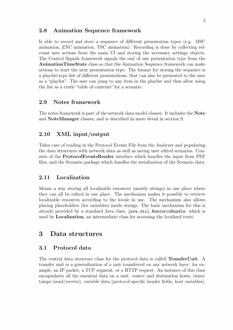
The central data structure class for the protocol data is called TransferUnit. Atransfer unit is a generalization of a unit transferred on any network layer: for ex-ample, an IP packet, a TCP segment, or a HTTP request. An instance of this classencapsulates all the essential data on a unit: source and destination hosts, times-tamps (send/receive), variable data (protocol-specific header fields, host variables),
6
Figure 2: Class diagram for the data structures
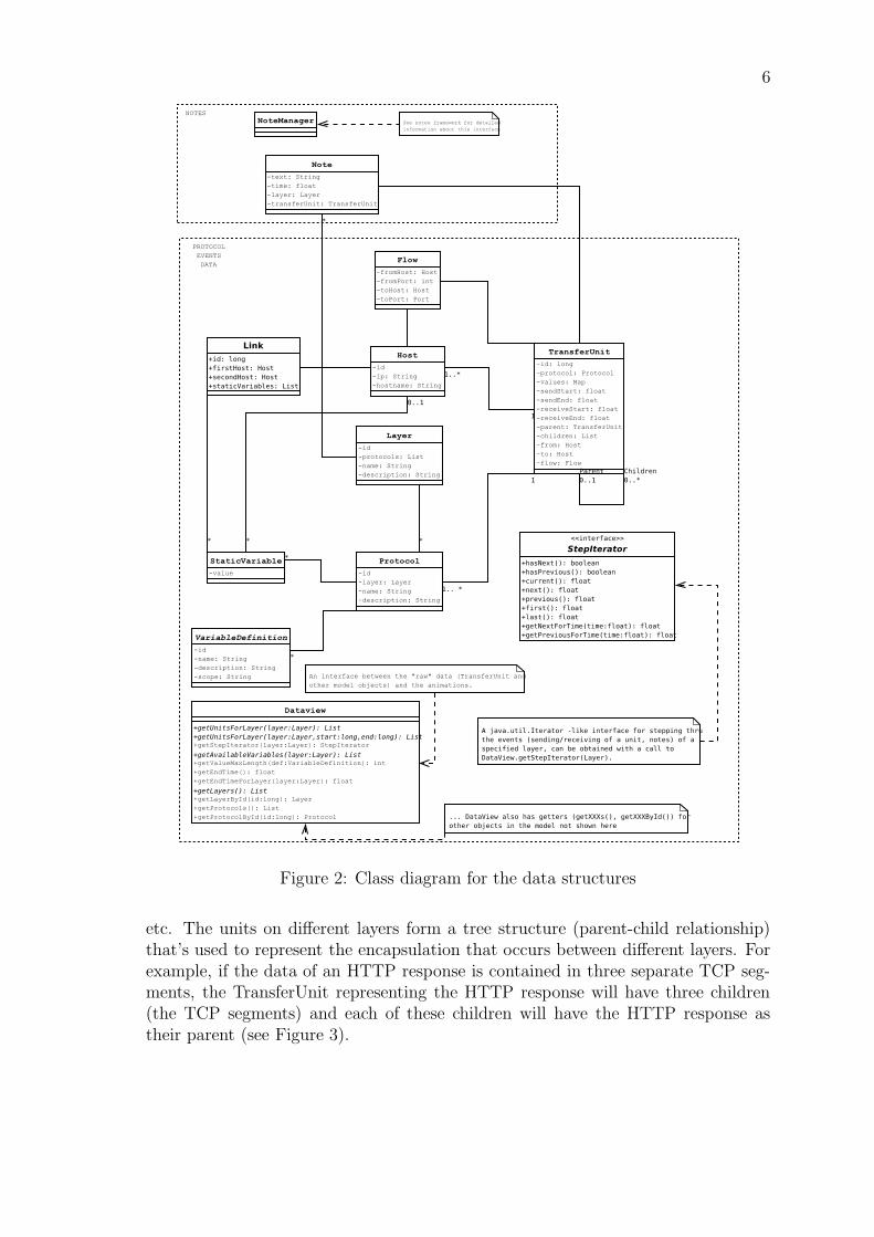
etc. The units on different layers form a tree structure (parent-child relationship)that’s used to represent the encapsulation that occurs between different layers. Forexample, if the data of an HTTP response is contained in three separate TCP seg-ments, the TransferUnit representing the HTTP response will have three children(the TCP segments) and each of these children will have the HTTP response astheir parent (see Figure 3).
7
Figure 3: Encapsulation in TransferUnit objects
In general, the data structures used to represent the protocol data in the Animatorare immutable, that is they will not (or can’t) be modified after they have beencreated. This in turn implies that they are thread-safe, and can be concurrentlyaccessed by multiple threads without using synchronized collection classes, for ex-ample.
3.2 Host class
The Host class holds information about a single host, containing the hostname (forinstance, ”A”) and the IP number in String format. A host is the network entitywhich interchanges packets (transfer units) with other hosts. References to hostsare maintained from the TransferUnit and the Connection classes.
3.3 Flow class
The Flow class contains information about a protocol-specific connection betweentwo hosts, for example a TCP connection. Therefore an instance of it makes refer-ences to both source and destination hosts, and as well stores information about theport numbers used for this connection to be established.
3.4 Link class
The Link class models a physical link between two hosts. It can have constantssuch as MTU (maximum transfer unit size) associated with it.
3.5 Protocol class
The Protocol class is intended for maintaining data about the name and the net-work layer of a given protocol. One protocol can only belong to one layer. There
8
must be at least one TransferUnit for that protocol, and it can have none or manyStaticVariables and VariableDefinitions.
3.6 Layer class
The Layer class represents a network stack layer. It is described by the namecommonly given to the layer. Many protocols can belong to a same layer.
3.7 VariableDefinition class
This class contains all useful information needed to describe a network variable,meaning that it contains a variable’s id (for Animator and Analyzer internal rep-resentation), the name of the variable, a short description and the variable scope.Depending on the scope of a variable, this one will be shown in different placesduring visualization. The name and description attributes are determined by theLocalization feature to adapt them to particular languages. A Protocol can havemany or no variables. The VariableDefinition class is be used for those variablesthat can change throughout the interchange of transfer units between the hosts, forinstance representing the value of the congestion window. Those dynamic variablesmust be mapped to TransferUnits as their value changes in relation to the packetinterchange. For static variables that are constant all through the packet interchangesequence, the value is represented with a StaticVariable instance.
3.8 StaticVariable class
A StaticVariable is a particular kind of VariableDefinition that is specific toa Host and a Protocol. This class contains a value attribute that will store theactual value of the network static variable. It is called static as it doesn’t changeduring the packet interchange. It extends from VariableDefinition.
3.9 Notes
Notes are separately discussed in, section 9, the Notes framework.
3.10 DataView interface
While a TransferUnit object contains all the necessary information that needs to bevisualized of a single protocol unit, different animation types need a way of accessingthe protocol data as a whole. The TransferUnit class has a way of representing theencapsulation between units on different layers, but has no mechanism for returningall the units on a specific layer in a sequential list, for example. This mechanism isneeded by the MSC animation type, for example, as it is only interested in units on
9
one specific layer at a time. Thus, there is a need for an interface that can providedifferent views to the ”raw” unit data (TransferUnit objects) for the rest of thesystem.
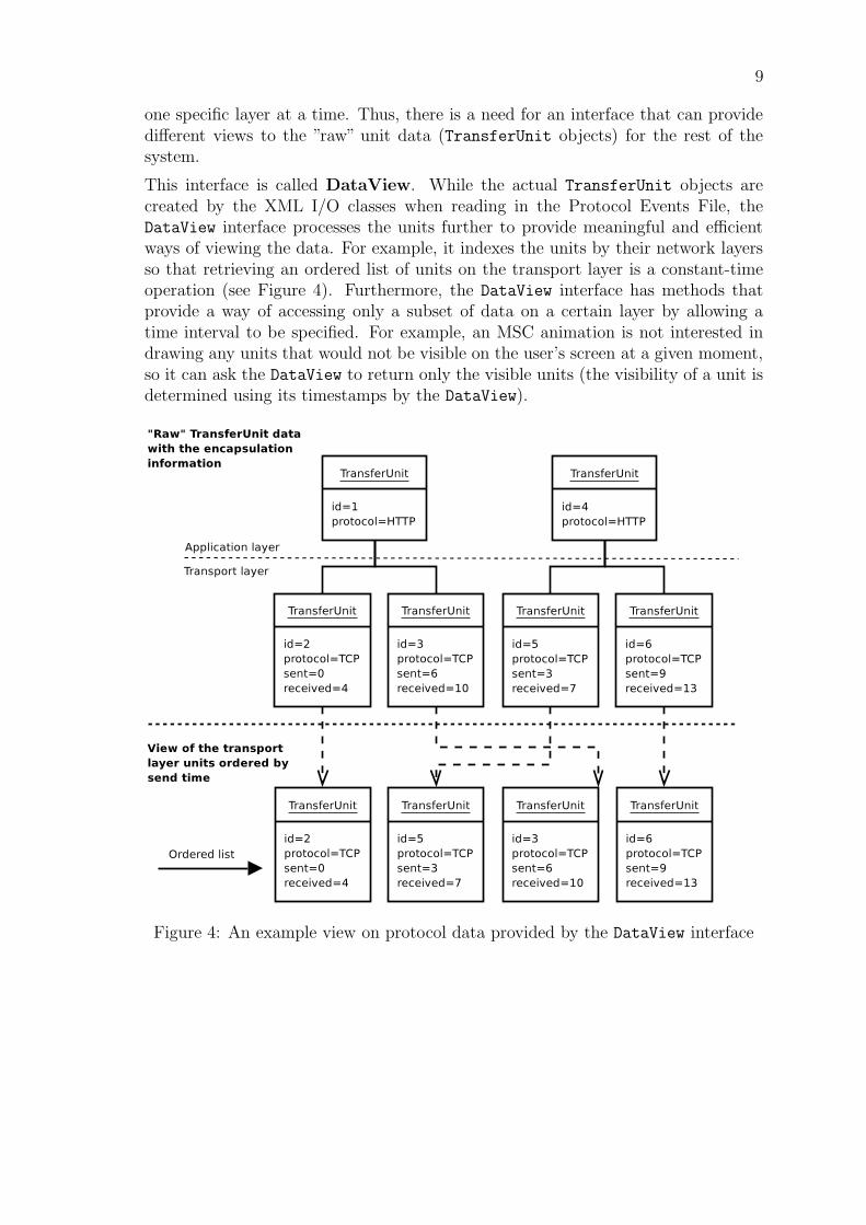
This interface is called DataView. While the actual TransferUnit objects arecreated by the XML I/O classes when reading in the Protocol Events File, theDataView interface processes the units further to provide meaningful and efficientways of viewing the data. For example, it indexes the units by their network layersso that retrieving an ordered list of units on the transport layer is a constant-timeoperation (see Figure 4). Furthermore, the DataView interface has methods thatprovide a way of accessing only a subset of data on a certain layer by allowing atime interval to be specified. For example, an MSC animation is not interested indrawing any units that would not be visible on the user’s screen at a given moment,so it can ask the DataView to return only the visible units (the visibility of a unit isdetermined using its timestamps by the DataView).
Figure 4: An example view on protocol data provided by the DataView interface
10
3.11 StepIterator interface
For stepping thru the animations (MSC in particular) in a meaningful way, certainsteps need to be calculated from the protocol data. A special interface, StepIterator,provides the animations with a means of stepping thru the events of a certain layer:sending and receiving units as well as any notes on the layer.
4 Main User Interface design
status bar
main animation area secondary area
tool bar
menu bar
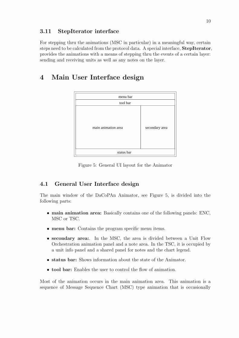
Figure 5: General UI layout for the Animator
4.1 General User Interface design
The main window of the DaCoPAn Animator, see Figure 5, is divided into thefollowing parts:
• main animation area: Basically contains one of the following panels: ENC,MSC or TSC.
• menu bar: Contains the program specific menu items.
• secondary area:. In the MSC, the area is divided between a Unit FlowOrchestration animation panel and a note area. In the TSC, it is occupied bya unit info panel and a shared panel for notes and the chart legend.
• status bar: Shows information about the state of the Animator.
• tool bar: Enables the user to control the flow of animation.
Most of the animation occurs in the main animation area. This animation is asequence of Message Sequence Chart (MSC) type animation that is occasionally
11
interrupted with some Encapsulation (ENC) animation. Alternatively, the mainanimation area shows a Time Sequence Chart (TSC) animation. The animation canbe watched in two modes: scenario mode and explore mode. In scenario mode theanimation follows a predefined script and in explore mode the user is in charge ofcontrolling the animation flow.
The main animation area takes up most of the screen width and is positioned on theleft side of the program frame. The right side is used by the secondary area and isdivided vertically in two parts. The areas are divided using Swing Splitpanes, sothat the user can easily drag them to a preferred size. The animation panels thenknow how to draw themselves according to the space given to them.
When starting the Animator, no animation panels are shown as there is no file loadedto the memory. Instead a welcome screen is shown in the main animation area.
4.2 The functionality of the main UI classes
The DaCoPAn animator is based on the Swing framework, which means that thecontrol over the software runs always through Swing, which in turn gives the controlover the other parts of the program to MainFrame (i.e. the main UI classes). Whenthe Animator is started, an instance of MainFrame is created. It then creates the userinterface using the class UserInterface and instances of all other classes needed bythe different animation modes: DataView for accessing the data structures, Note-Manager for using notes, AnimationSequence for storing scenario information. Aninstance of AnimationTimeState is created when the animation is started.
After this the Animator is in a state called DACOPAN STATE NO FILE and in amode DACOPAN NO MODE, which indicates that the animator doesn’t do any-thing before the user uses the menu or tool bar to open a file.
MainFrame can be in the following modes:
• DACOPAN NO MODE: Used when no animation file has been loaded.
• DACOPAN EXPLORE MODE
• DACOPAN SCENARIO MODE
MainFrame also has three distinct states:
• DACOPAN STATE NO FILE: Used when no animation has been loaded.
• DACOPAN STATE PLAYING ENC: Used when the animator is showing En-capsulation animation.
• DACOPAN STATE PLAYING MSC: Used when the animator is showing MSCanimation.
12
• DACOPAN STATE PLAYING TSC: Used when the animator is showing TSCanimation.
Distinction between play and pause mode is done by AnimationTimeState andtherefore those are not distinct states from the point of view of MainFrame.
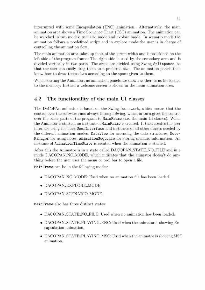
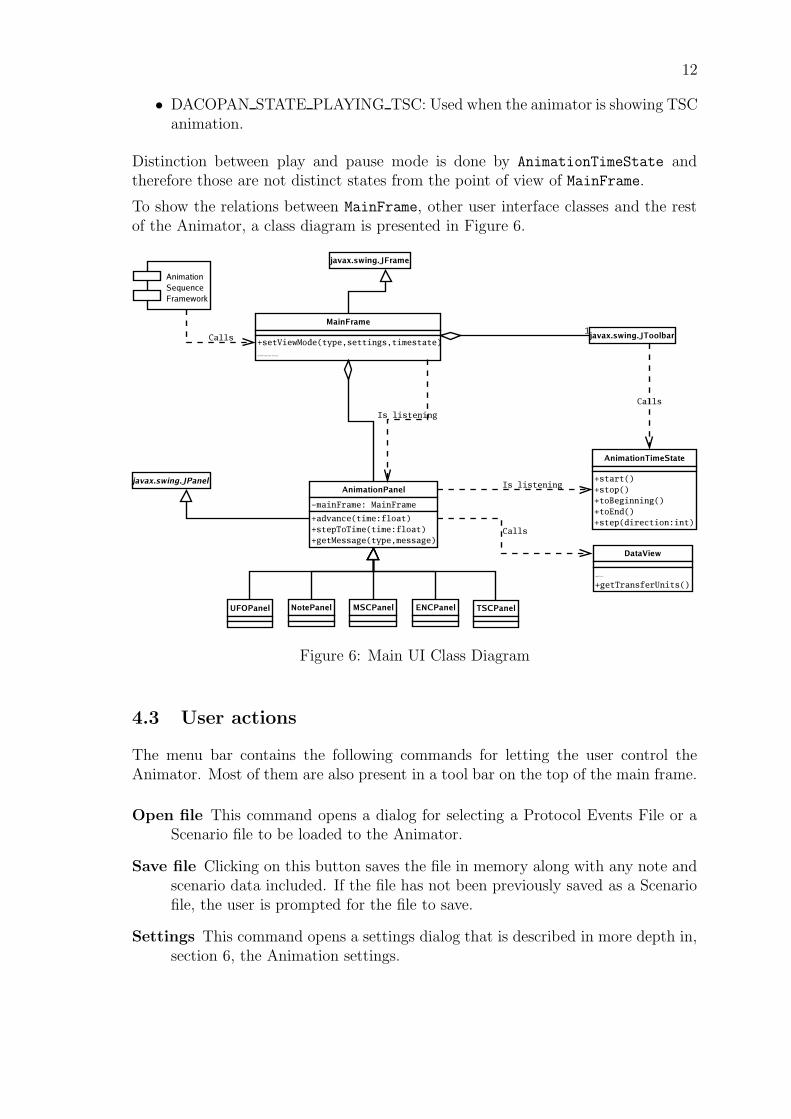
To show the relations between MainFrame, other user interface classes and the restof the Animator, a class diagram is presented in Figure 6.
Figure 6: Main UI Class Diagram
4.3 User actions
The menu bar contains the following commands for letting the user control theAnimator. Most of them are also present in a tool bar on the top of the main frame.
Open file This command opens a dialog for selecting a Protocol Events File or aScenario file to be loaded to the Animator.
Save file Clicking on this button saves the file in memory along with any note andscenario data included. If the file has not been previously saved as a Scenariofile, the user is prompted for the file to save.
Settings This command opens a settings dialog that is described in more depth in,section 6, the Animation settings.
13
Save all settings This command is available in the Settings menu and saves alluser specific settings globally.
Rewind to the beginning This buttons rewinds the animation to the beginningof the current AnimationTimeState. This command can only be called whenthe animation is paused.
Play Calls the current AnimationTimeState to start playing the animation it isassosiated with. If the current sequence is part of a bigger scenario, the Ani-
mationTimeState notifies the animation sequence about reaching the end ofthe animation.
Pause Pressing this button changes the animation to paused mode.
Fast forward to the end This button steps to the end of the animation data as-sosiated with the current AnimationTimeState.
Step forward When in stop/scroll mode, this button can be used to step forwardthrough events one by one in the animation.
Step backward When in stop/scroll mode, this button can be used to step back-ward through events one by one in the animation.
Animator mode selection The Animator can be in either explore or scenariomode. The user can do this selection in the menu. In the status bar thecurrently selected mode is highlighted and in scenario mode a small windowfor controlling the scenario and recording a play list is presented. When thiswindow is closed, MainFrame minimizes it to the status bar as a button forrestoring the window.
Layer selection The user can select the layer that is currently shown by clickingthe button of the layer he wants to see either in the menu or on the tool bar.When such a button is pushed, all animation panels are recreated with correctsettings.
Language selection When the user selects a new language, the whole user inter-face is recreated using the strings from the selected language. This is done bycalling UserInterface method recreateUI.
Help The help command opens a new window with an HTML help document shownin it.
About The about command opens a window with tabs for general information,licence information and information on the team behind the product.
14
5 Animation panels
All the animation panels that can be placed on the four animation panel spaces in theAnimator have to extend the abstract class AbstractAnimationPanel. This classhandles some aspects of the communication between the panels and the MainFrame.It also implements the interface ControlSignalListener that allows the panels toreceive control signals from the Control Signal framework.
In this version of the Animator five animation panels are created:
• Message Sequence Chart
• Time Sequence Chart
• Encapsulation
• Unit Flow Orchestration
• Notes
The animation panels are described in more detail in the following subsections.
5.1 Message Sequence Chart
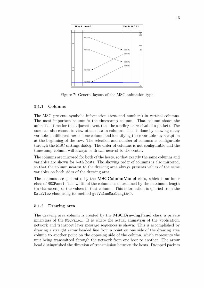
The Message Sequence Chart (MSC) animation type, see Figure 7, is one of the twoprimary animation types for the DaCoPAn2 Animator. It shows unit transfers in“text-book” style, that is, by drawing lines from one host to another. The y-axisrepresents time and the gradient of a line is proportional to the transfer delay of aunit. The central column is the drawing area, where the lines are drawn. On bothsides of the drawing area there are up to two optional columns, where timestampsand other information is displayed. The third column, the notes column, is alwaysvisible. Above the columns there is a host field, which lists the names for hosts Aand B.
The blue line is the progress line, which scrolls down the display area as the anima-tion proceeds in play mode. The display area is vertically scrollable. Also, when theprogress line is moved away from the drawing area with the mouse, via click anddrag, past the top or bottom panel border, the MSC panel will scroll.
The MSC animation style is created by class MSCPanel, which implements theinterface AbstractAnimationPanel. Because of this MSCPanel also implementsthose methods that are listed in section 7.2.
The properties and functionality of the MSC animation type are explained in thefurther subsections.
15
0.056782
0.0867820.086782
0.096782
0.116782
0.126782
0.136782
0.166782
Host B 10.0.0.1Host A 10.0.0.2
Figure 7: General layout of the MSC animation type
5.1.1 Columns
The MSC presents symbolic information (text and numbers) in vertical columns.The most important column is the timestamp column. That column shows theanimation time for the adjacent event (i.e. the sending or receival of a packet). Theuser can also choose to view other data in columns. This is done by showing manyvariables in different rows of one column and identifying those variables by a captionat the beginning of the row. The selection and number of columns is configurablethrough the MSC settings dialog. The order of columns is not configurable and thetimestamp column will always be drawn nearest to the center.
The columns are mirrored for both of the hosts, so that exactly the same columns andvariables are shown for both hosts. The showing order of columns is also mirrored,so that the column nearest to the drawing area always presents values of the samevariables on both sides of the drawing area.
The columns are generated by the MSCColumnModel class, which is an innerclass of MSCPanel. The width of the columns is determined by the maximum length(in characters) of the values in that column. This information is queried from theDataView class using its method getValueMaxLength().
5.1.2 Drawing area
The drawing area column is created by the MSCDrawingPanel class, a privateinnerclass of the MSCPanel. It is where the actual animation of the application,network and transport layer message sequences is shown. This is accomplished bydrawing a straight arrow headed line from a point on one side of the drawing areacolumn to another point on the opposing side of the column, which represents theunit being transmitted through the network from one host to another. The arrowhead distinguished the direction of transmission between the hosts. Dropped packets
16
are marked with a red cross, which is drawn close to the opposing end of the columnfrom the sending host’s side. In addition to this, via the settings, the user can selectthe unit’s variables to be drawn above the line. The font size for this text can alsobe chosen from the settings.
See subsection 5.1.4 for more detail on the implementation of the drawing area.
5.1.3 Notes
The presence of a note is signaled by showing a small icon in a notes column thatis always present as the left-most column next to the left edge of the component.(That column is never mirrored, as there is only one notes column.) The top edge ofthe icon corresponds to the exact location of the note on the y-axis. The actual notetext is displayed in the Note panel, situated on the bottom half of the secondaryarea of the main window.
See subsection 9.1 for more information about MSC notes.
5.1.4 Improving the readability of the MSC
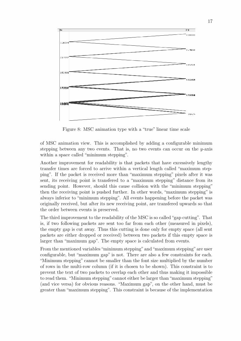
One of the main problems with the previous DaCoPAn version was in representinga “clear”visualization of data for the MSC animation type. The problem arises fromthe fact that, usually, there are lots of packets sent within a very short period of time.The scaling for the y-axis (time) would have to be in the order of microseconds (µs),to distinguish separate events from each other in the drawing area. Additionally,the separation of events ranges from atleast 2 µs to about 700 µs. This leads tooverlapping lines if the scale is too large, as seen in Figure 8, or in lines that havenearly vertical gradients. In the latter case the scale is simply too small, which causesa network transmission of 2 seconds to stretch over several hundred A4 lengths inthe drawing area. Clearly neither is acceptable.
The constraints imposed on the improvement of the MSC animation view are hence:
1) The scaling, separation of adjacent packets, for the vertical time coordinates forthe animation view is limited.
2) For packets with very lengthy transfer delays, the gradient for drawn lines isexcessively large (almost vertical), depending upon the scaling used.
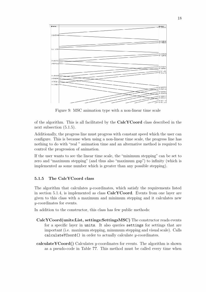
As both constraints make it very difficult to read the MSC diagram and distinguishseparate events, the DaCoPAn2 projects version of the Animator allows the user toforce the program to leave some space between consecutive events. It also allows theuser to force a maximum length for the separation of both points of a single drawnline. This, of course, removes the strict linearity of time for the y-axis. This modifiedanimation mode is referred to as the “non-linear time” mode, whereas the previousversion is called the “true time linear mode”. In Figure 9, a view of the non-linearmode for the MSC animation type which distinguishes packets is presented.
As mentioned above, the DaCoPAn2 project must be able to improve the readability
17
Figure 8: MSC animation type with a “true” linear time scale
of MSC animation view. This is accomplished by adding a configurable minimumstepping between any two events. That is, no two events can occur on the y-axiswithin a space called “minimum stepping”.
Another improvement for readability is that packets that have excessively lengthytransfer times are forced to arrive within a vertical length called “maximum step-ping”. If the packet is received more than “maximum stepping” pixels after it wassent, its receiving point is transfered to a “maximum stepping” distance from itssending point. However, should this cause collision with the “minimum stepping”then the receiving point is pushed further. In other words, “maximum stepping” isalways inferior to “minimum stepping”. All events happening before the packet wasoriginally received, but after its new receiving point, are transfered upwards so thatthe order between events is preserved.
The third improvement to the readability of the MSC is so called“gap cutting”. Thatis, if two following packets are sent too far from each other (measured in pixels),the empty gap is cut away. Thus this cutting is done only for empty space (all sentpackets are either dropped or received) between two packets if this empty space islarger than “maximum gap”. The empty space is calculated from events.
From the mentioned variables“minimum stepping”and“maximum stepping”are userconfigurable, but “maximum gap” is not. There are also a few constraints for each.“Minimum stepping” cannot be smaller than the font size multiplied by the numberof rows in the multi-row column (if it is chosen to be shown). This constraint is toprevent the text of two packets to overlap each other and thus making it impossibleto read them. “Minimum stepping”cannot either be larger than“maximum stepping”(and vice versa) for obvious reasons. “Maximum gap”, on the other hand, must begreater than “maximum stepping”. This constraint is because of the implementation
18
Figure 9: MSC animation type with a non-linear time scale
of the algorithm. This is all facilitated by the CalcYCoord class described in thenext subsection (5.1.5).
Additionally, the progress line must progress with constant speed which the user canconfigure. This is because when using a non-linear time scale, the progress line hasnothing to do with “real ” animation time and an alternative method is required tocontrol the progression of animation.
If the user wants to see the linear time scale, the “minimum stepping” can be set tozero and “maximum stepping” (and thus also “maximum gap”) to infinity (which isimplemented as some number which is greater than any possible stepping).
5.1.5 The CalcYCoord class
The algorithm that calculates y-coordinates, which satisfy the requirements listedin section 5.1.4, is implemented as class CalcYCoord. Events from one layer aregiven to this class with a maximum and minimum stepping and it calculates newy-coordinates for events.
In addition to the constructor, this class has few public methods:
CalcYCoord(units:List, settings:SettingsMSC) The constructor reads eventsfor a specific layer in units. It also queries settings for settings that areimportant (i.e. maximum stepping, minumum stepping and visual scale). CallscalculateYCoord() in order to actually calculate y-coordinates.
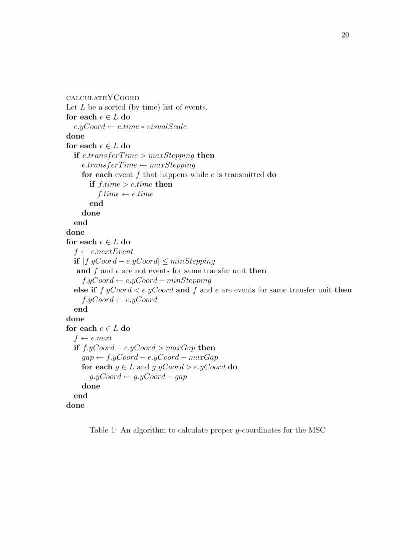
calculateYCoord() Calculates y-coordinates for events. The algorithm is shownas a pseudo-code in Table ??. This method must be called every time when
19
something interacting with y-coordinate changes.
getYCoordForTime(time:float):int Returns the y-coordinate for given time.If some event has the same time as the argument, it returns the exact y-coordinate. Otherwise, it calculates linear interpolation based on y-coordinatesof the nearest events.
getLinearYCoordForTime(time:float):int Returns the y-coordinate, such thatthe ratio between it and the last y-coordinate of events is equal to the ratiobetween the given time and the time of the last event.
getTimeForYCoord(yCoord:int):float Returns the time for a given y-coordinate.Acts as inverse function to getYCoordForTime, that is
t = getTimeForYCoord(getYCoordForTime(t)).
getLinearTimeForYCoord(yCoord:int):float As with getTimeForYCoord, butfor getLinearYCoordForTime.
20
calculateYCoord
Let L be a sorted (by time) list of events.for each e ∈ L do
e.yCoord← e.time ∗ visualScaledonefor each e ∈ L do
if e.transferT ime > maxStepping thene.transferT ime← maxSteppingfor each event f that happens while e is transmitted do
if f.time > e.time thenf.time← e.time
enddone
enddonefor each e ∈ L do
f ← e.nextEventif |f.yCoord− e.yCoord| ≤ minSteppingand f and e are not events for same transfer unit thenf.yCoord← e.yCoord + minStepping
else if f.yCoord < e.yCoord and f and e are events for same transfer unit thenf.yCoord← e.yCoord
enddonefor each e ∈ L do
f ← e.nextif f.yCoord− e.yCoord > maxGap then
gap← f.yCoord− e.yCoord−maxGapfor each g ∈ L and g.yCoord > e.yCoord do
g.yCoord← g.yCoord− gapdone
enddone
Table 1: An algorithm to calculate proper y-coordinates for the MSC
21
5.2 Encapsulation
The Encapsulation animation occupies the main frame when it is activated. TheUFO panel is cleared and disabled, and the Note panel displays the note of thespecific ENC animation.
The ENC animation is a static diagram which shows a snapshot at a specific time.The user actions for controlling the animation via the Animation menu and the toolbar buttons are disabled.
5.2.1 Note framework for ENC
Each ENC animation can contain a single note. The note is bound to the Trans-
ferUnit from which the ENC diagram is constructed. The note can be retrievedfrom NoteManager by calling the method getEncNote(TransferUnit) with theactive ENC unit as the parameter.
5.2.2 The ENC tree model
The generation of the encapsulation tree for an ENC animation is the responsibilityof a class called ENCTreeModel. This class contains all the logic needed to selectthe most interesting units in the encapsulation tree of a selected unit for display inthe animation. By default the tree model produces ENC trees with a maximum ofthree units on the same level.
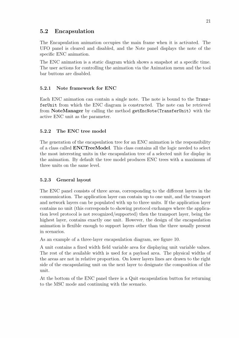
5.2.3 General layout
The ENC panel consists of three areas, corresponding to the different layers in thecommunication. The application layer can contain up to one unit, and the transportand network layers can be populated with up to three units. If the application layercontains no unit (this corresponds to showing protocol exchanges where the applica-tion level protocol is not recognized/supported) then the transport layer, being thehighest layer, contains exactly one unit. However, the design of the encapsulationanimation is flexible enough to support layers other than the three usually presentin scenarios.
As an example of a three-layer encapsulation diagram, see figure 10.
A unit contains a fixed width field variable area for displaying unit variable values.The rest of the available width is used for a payload area. The physical widths ofthe areas are not in relative proportion. On lower layers lines are drawn to the rightside of the encapsulating unit on the next layer to designate the composition of theunit.
At the bottom of the ENC panel there is a Quit encapsulation button for returningto the MSC mode and continuing with the scenario.
22
Figure 10: The Encapsulation diagram
23
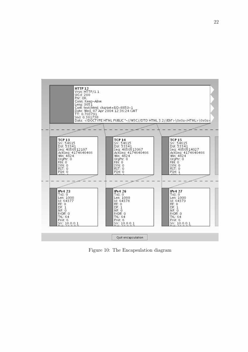
5.3 Unit Flow Orchestration
The UFO panel is designed to visualize the message sequence data as a continuousanimated flow of units moving between hosts. It has two channel areas for animatingthe movement of the units and two unit variable fields for showing the data that iscontained by the selected transfered units, one for each direction. See figure 11, forthe main layout of the UFO panel.
Show encapsulation Show encapsulation
A B[layer_name]:[protocol_name]
Figure 11: Empty UFO panel displayed in the ENC view
The UFO panel is a subclass of AbstractAnimationPanel which in turn imple-ments the ControlSignalListener interface. This means that it has the methodstepTo() in which it is asked to update to a new animation state. When the UFOpanel is drawn, it calculates the position for each unit and draws them to the correctplace on the appropriate channel. To synchronize the UFO animation with the MSCanimation, the UFO uses the CalcYCoord class to get the Y coordinates of the sendand receive events of units in the MSC panels, and uses them to calculate the units’X coordinate on the channel. Because the UFO panel is synchronised with the MSCpanel, the amount of units drawn on top of each other is minimized, but when unitlines intersect in the MSC animation, the corresponding units are also drawn on theexact same place in the UFO animation.
The data of the active units is shown in the data areas. When a new unit appearsto the visible area, it is selected as the active unit. The selected unit stays selecteduntil it is received. Units are activated automatically when they are created, so thatthe latest unit is always the default active unit.
Another important use for the UFO panel is that it can be used to move intoencapsulation mode. There are two buttons under the data fields that can be usedto show the encapsulation for the selected unit. When a unit is active, this button
24
can be clicked. The main frame switches to showing encapsulation instead of MSCanimation.
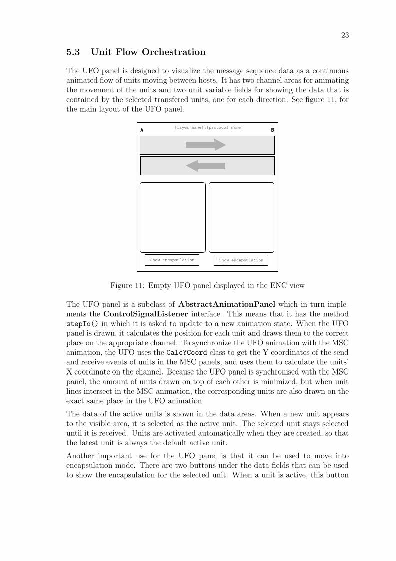
The two channels (pipes) contain only one color of units each, which have a darkerborder when they are active. Dropped packets are marked with a red cross, anddisappear when they arrive at the center of the channel.
Show encapsulation Show encapsulation
A B[layer_name]:[protocol_name]
Header_field1 = Value1Header_field2 = Value2Header_field3 = Value3Header_field4 = Value4Header_field5 = Value5Header_field6 = Value6
Header_field1 = Value1Header_field2 = Value2Header_field3 = Value3
Header_field5 = Value5Header_field6 = Value6
Figure 12: UFO panel in play mode
5.4 Time Sequence Chart
The Time Sequence Chart (TSC) is an animation type, which shows detailed in-formation about the status of transport layer communication between two hosts.Its main function is to illustrate TCP layer communication. The TSC animationdoesn’t use the same Control Signal framework (ControlSignalsListener inter-face) that the other animation panels use, since the other animation types are timebased, which the TSC is not. The TSC component has its own thread to ani-mate the display. The animation is “user friendly”, which means that the Animatordraws graphical elements using delays between draws. For example, when a no-tice is attached to a drawn transfer unit, the delay amount is determined from a“event/second” slider in the TSC settings.
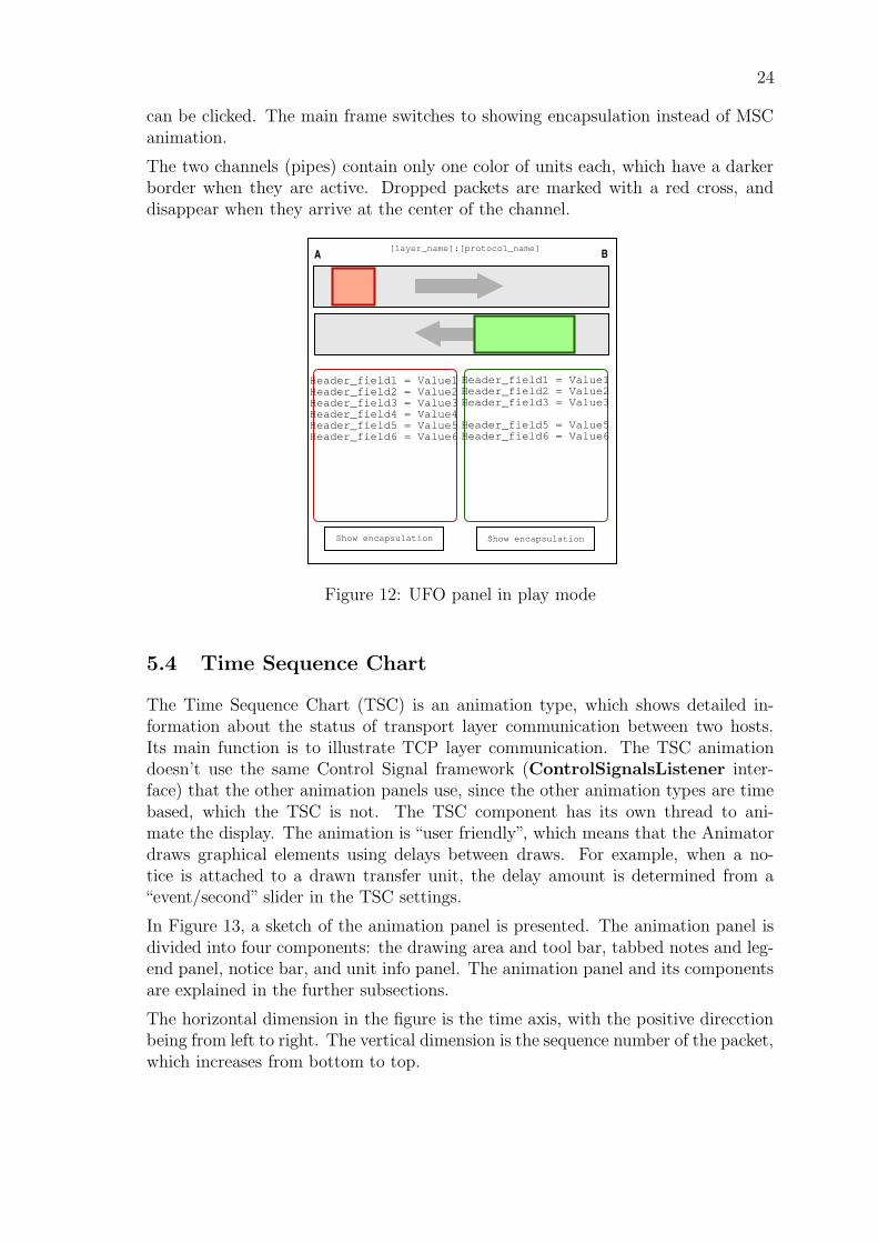
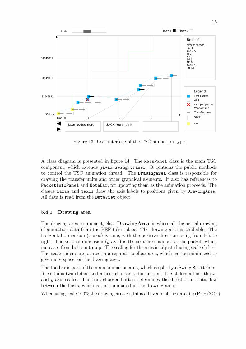
In Figure 13, a sketch of the animation panel is presented. The animation panel isdivided into four components: the drawing area and tool bar, tabbed notes and leg-end panel, notice bar, and unit info panel. The animation panel and its componentsare explained in the further subsections.
The horizontal dimension in the figure is the time axis, with the positive direcctionbeing from left to right. The vertical dimension is the sequence number of the packet,which increases from bottom to top.
25
Figure 13: User interface of the TSC animation type
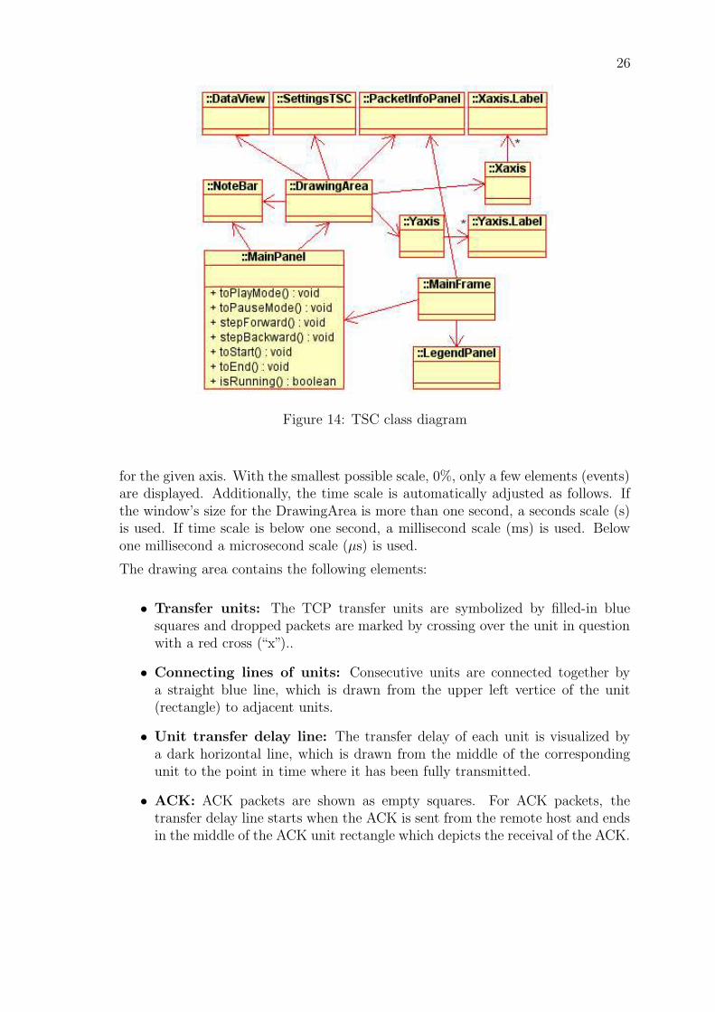
A class diagram is presented in figure 14. The MainPanel class is the main TSCcomponent, which extends javax.swing.JPanel. It contains the public methodsto control the TSC animation thread. The DrawingArea class is responsible fordrawing the transfer units and other graphical elements. It also has references toPacketInfoPanel and NoteBar, for updating them as the animation proceeds. Theclasses Xaxis and Yaxis draw the axis labels to positions given by DrawingArea.All data is read from the DataView object.
5.4.1 Drawing area
The drawing area component, class DrawingArea, is where all the actual drawingof animation data from the PEF takes place. The drawing area is scrollable. Thehorizontal dimension (x-axis) is time, with the positive direction being from left toright. The vertical dimension (y-axis) is the sequence number of the packet, whichincreases from bottom to top. The scaling for the axes is adjusted using scale sliders.The scale sliders are located in a separate toolbar area, which can be minimized togive more space for the drawing area.
The toolbar is part of the main animation area, which is split by a Swing SplitPane.It contains two sliders and a host chooser radio button. The sliders adjust the x-and y-axis scales. The host chooser button determines the direction of data flowbetween the hosts, which is then animated in the drawing area.
When using scale 100% the drawing area contains all events of the data file (PEF/SCE),
26
Figure 14: TSC class diagram
for the given axis. With the smallest possible scale, 0%, only a few elements (events)are displayed. Additionally, the time scale is automatically adjusted as follows. Ifthe window’s size for the DrawingArea is more than one second, a seconds scale (s)is used. If time scale is below one second, a millisecond scale (ms) is used. Belowone millisecond a microsecond scale (µs) is used.
The drawing area contains the following elements:
• Transfer units: The TCP transfer units are symbolized by filled-in bluesquares and dropped packets are marked by crossing over the unit in questionwith a red cross (“x”)..
• Connecting lines of units: Consecutive units are connected together bya straight blue line, which is drawn from the upper left vertice of the unit(rectangle) to adjacent units.
• Unit transfer delay line: The transfer delay of each unit is visualized bya dark horizontal line, which is drawn from the middle of the correspondingunit to the point in time where it has been fully transmitted.
• ACK: ACK packets are shown as empty squares. For ACK packets, thetransfer delay line starts when the ACK is sent from the remote host and endsin the middle of the ACK unit rectangle which depicts the receival of the ACK.
27
• SACK: The SACK blocks are drawn as vertical violet lines directly abovethe corresponding ACK packet. The lines’ vertical coordinates represent thesequence numbers of the SACK blocks.
• SYN: The packets with SYN flags are highlighted using a diffrent color fromother units, chosen by the user from the settings. The default color of theunits is yellow.
• Window size: The window size of the receiver is represented by a continuousgreen line which grows in discrete (ladder-like) steps. The distance from theACK packet to the horizontal level of the line directly above it represents theactual window size.
• Grid: The grid is drawn using horizontal and vertical lines drawn at regularintervals, which are dependent on the scaling used for the axes.
• Crosshair: The crosshair consists of a dashed horizontal and vertical line,which intersects over the highlighted unit. During animation, the latest drawnpacket is highlighted. The user can also choose the highlighted packet withthe mouse, by clicking on it.
5.4.2 Legend
The Legend panel is located in the same tabbed panel as the Notes panel. It containsthe description for the used graphical symbols. The legend contains only thosesymbols, which are selected for display from the settings.
5.4.3 Notes
The Notes panel is located in the same tabbed panel as the Legend panel. Notesuse the same Notes framework as in the MSC view. The text in the Notes panel,if any, is specific to the active unit. TSC notes are independent from MSC/ENCnotes, meaning that separate texts are shown in each view.
See subsection 9.3 for more information about TSC notes.
5.4.4 Notices
The notice bar component, generated by class NoteBar, displays the automaticallygenerated or user added notices. Notice bar is scrollable, since it may contain morenotice elements than fits into the area. The notice bar only contains notice elementscorresponding to current events, which are visible in the drawing area.
Below the drawing area is a notice bar component (NoteBar class), which displaysthe automatically generated or user added notices.
28
Notices are attached to transfer units using connecting lines. Since the notice barand drawing area are separate Swing components, the line drawing is done in theparent component MainPanel.
Notices (aka. the balloons) are clearly distinguishable from notes, which are in thesame tabbed panel with the legend table. The active unit’s notice text, if any, isduplicated in the Notes panel. Notices are edited through the Notes panel in thetabbed panel.
See subsection 9.3 for more information about TSC notes/notices.
5.4.5 Unit Info panel
The Unit Info panel, generated by the UnitInfoPanel class, contains the variablesof the active transfer unit. In addition to transport layer data, it can display networklayer data. The displayed data variables are configured from the TSC settings. Theuser may select the unit to be displayed by clicking on it in the drawing area.Additionally, the active unit changes during animation by using the step-forwardsand step-backwards buttons. The active unit is highlighted in the drawing areausing a red border.
6 Animation settings
The animator has to keep track of the settings that the user has chosen to beused to visualize the different events contained in the Protocol Events File. In thissection, the classes implementing the settings are described, and an explanation ofthe settings user interface panels is given.
6.1 Settings class structure
The user can access the settings using the dialog SettingsPanel in which the othersettings panel classes are embedded. All the settings panels are javax.swing.JPanels.
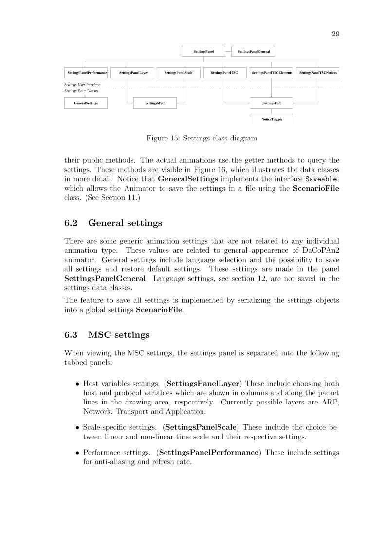
The settings are stored in the settings data classes. See Figure 15, for a class diagramof all the relevant classes. In the diagram, the classes above the dashed line are partof the user interface, and the classes below it are the settings data classes.
The settings dialog is implemented as the class SettingsPanel, which is respon-sible for setting up all the other settings panels, where the actual settings aremade. It includes a selector where the user can browse between settings for theMessage Sequence Chart and the Time Sequence Chart animation types and gen-eral settings. It also includes an Apply-button, which immediately saves all settingsmade in the currently open settings panel, and updates the animation settings usingMainFrame.refreshSettings().
The settings dialog sets and queries the fields of the settings data classes through
29
SettingsPanel
Settings Data Classes
SettingsPanelPerformance SettingsPanelTSCElementsSettingsPanelScale SettingsPanelTSC SettingsPanelTSCNotices
SettingsTSC
NoticeTrigger
SettingsMSCGeneralSettings
Settings User Interface
SettingsPanelGeneral
SettingsPanelLayer
Figure 15: Settings class diagram
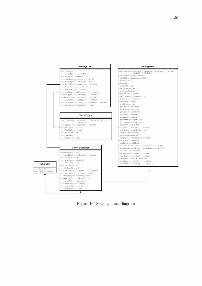
their public methods. The actual animations use the getter methods to query thesettings. These methods are visible in Figure 16, which illustrates the data classesin more detail. Notice that GeneralSettings implements the interface Saveable,which allows the Animator to save the settings in a file using the ScenarioFileclass. (See Section 11.)
6.2 General settings
There are some generic animation settings that are not related to any individualanimation type. These values are related to general appearence of DaCoPAn2animator. General settings include language selection and the possibility to saveall settings and restore default settings. These settings are made in the panelSettingsPanelGeneral. Language settings, see section 12, are not saved in thesettings data classes.
The feature to save all settings is implemented by serializing the settings objectsinto a global settings ScenarioFile.
6.3 MSC settings
When viewing the MSC settings, the settings panel is separated into the followingtabbed panels:
• Host variables settings. (SettingsPanelLayer) These include choosing bothhost and protocol variables which are shown in columns and along the packetlines in the drawing area, respectively. Currently possible layers are ARP,Network, Transport and Application.
• Scale-specific settings. (SettingsPanelScale) These include the choice be-tween linear and non-linear time scale and their respective settings.
• Performace settings. (SettingsPanelPerformance) These include settingsfor anti-aliasing and refresh rate.
30
SettingsTSC
+SettingsTSC()
+settingsTSC(settingsTSC)
+getAnimationSpeed(): float
+getDisplayedElements(): int []
+getDisplayedData(): String []
+getNoticeTriggers(): NoticeTrigger []
+getColor(element:int): Color
+isRelativeSEQ(): boolean
+switchDisplayedElement(int): boolean
+addTrigger(NoticeTrigger): boolean
+addDisplayedElement(int): boolean
+setAnimationSpeed(float): boolean
+setColor(color:Color,int:element): boolean
+setRelativeSEQ(boolean): void
NoticeTrigger
+NoticeTrigger(variable:String,value:String, test:int)
+triggered(TransferUnit): boolean
+getNotice(): String
+setVariable(String)
+setValue(String)
+setTest(int)
+setNotice(String)
0...*
SettingsMSC
+SettingsMSC(Host,Host,Layer,VariableDefinition [], VariableDefinition [])
+SettingsMSC(SettingsMSC)
+setAllFields(SettingsMSC)
+getEndTime()
+getLayer()
+getLeftHost()
+getRightHost()
+getScaleMode()
+getScaleMultiplier()
+getScaleMultiplierUnit()
+getScenarioAutoPlay()
+getStartTime()
+getTimeScale()
+getVariablesCenter()
+getVariablesCenter()
+getVariablesColumns()
+getVisualScale()
+getVisualScale()
+getMinStepping(): int
+getMaxStepping(): int
+getFontSize(): int
+isLinearTimeScale(): boolean
+showTimeStamps(): boolean
+setEndTime(float)()
+setScaleMode(int)()
+setScenarioAutoPlay(boolean)
+setStartTime(float)()
+setTimeScale(float)()
+setVariablesCenter(VariableDefinition[])
+setVariablesColumns(VariableDefinition[])
+setVisualScale(int)
+setMaxStepping(int): boolean
+setMinStepping(int): boolean
+setFontSize(int): boolean
+setLinearTimeScale(): boolean
+switchShowTimeStamps(): boolean
*
GeneralSettings
+GeneralSettings()
+GeneralSettings(GeneralSettings)
+getAntiAliasing()
+getListSettingsMSC()
+getDefaultLayer()
+getRefreshRate()
+getRefreshDelay()
+getSettingsMSC(Layer): SettingsMSC
+getSettingsTSC(): SettingsTSC
+addSettingsMSC(SettingsMSC)
+addSettingsTSC(SettingsTSC)
+setAntiAliasing(boolean)
+setDefaultLayer(Layer)
+setRefreshDelay(int)
+setRefreshRate(int)
Saveable
+setData(Object)
+getData(): Object
Figure 16: Settings class diagram
31
In the host variables settings the user can choose whether or not the time stampcolumn is shown and which host variables are shown in the variables column. Theuser can also choose which protocol variables are drawn along the packet line in thedrawing area. These settings are stored in SettingsMSC objects.
In scale-specific settings the user can choose between a linear and non-linear timescale. If the user chooses the linear time scale, he can adjust the following settings:
• Scale mode: Defines a factor of scale to draw the MSC animation. (e.g.Seconds to seconds: one second of network time is animated in one second).
• Visual Scale: Adjusts the number of pixels used in the MSC animation todraw one unit of network time.
• Time Scale: Number of seconds that it takes for the animation to show oneunit of network time. Higher values mean that the animation will move slower.
If the user, on the other hand, chooses the non-linear time scale he can adjust thefollowing settings:
• Minimum stepping: The user can adjust the minimum space left betweenany consecutive events. However, the user cannot adjust the minimum step-ping to be smaller than the current font size multiplied by the number of rowsin the multi-row column. When the minumum stepping is set smaller, the fontsize is scaled proportionally to be smaller.
• Maximum stepping: The user can adjust the maximum distance a line cantraverse in the drawing area. This maximum stepping cannot, however, besmaller than minimum stepping. If the maximum stepping is set to minimumstepping, the user will lose all time information on the y-axis.
• Font size: The user can freely choose the font size to be whatever availablevalue he wants. When the font size multiplied by the rows in the multi-row column is bigger than the minimum stepping, the minimum stepping isenlarged.
• Progress bar speed: User can set progress line speed on a pixels per secondbasis.
All the scale-specific settings listed above are stored in SettingsMSC objects.
In the performance settings, stored in GeneralSettings, the user can adjust thefollowing elements:
• Refresh delay: Sets the number of milliseconds between two refreshes of theanimation. Increasing its value means that the screen will be refreshed fewertimes in a second. The perception of the user is that the animations are lesssmooth in their movement, but the performance of the animation is increased.If the values are decreased the performance is worsened but the element in theanimation move more softly.
32
• Anti-Alias: Sets the smoothness of the elements drawn in the different screens.If the checkbox is selected the elements in the animations are drawn smoother,but on the other hand the performance of the animator is worsened. De-selecting it we get the inverse results, poor graphics but better performance.
In the MSC view, the settings dialog is adapted to the different animation modes,allowing changes only in the setting classes values specific to the active workingmode.
• Explore mode: the user is able to modify the performance settings, scale set-tings for all the layers in the animation and the variables and header fields toinclude in the animation for every existing layer in the animation.
• Scenario mode: due to the purpose of creating an item for the scenario playlist,a few settings can be tuned. These are the scale settings, and the header fieldsand variables. All of these can only be modified in the active layer.
There is a a separate SettingsMSC object for each layer. In explore mode, thesettings dialog applies the chosen settings for all of them. In th scenario mode onlythe settings for the SettingsMSC object of the current layer is modified.
6.3.1 SettingsMSC class
To fulfill the needs for the MSC settings a class SettingsMSC is implementedcontaining:
• List for the variables and header fields selected.
• Attributes to adjust the scale settings and the panels, i.e. scale mode, visualscale, time scale, max stepping, min stepping and font size.
• Variables that are needed for scenario files, i.e. start and end time from sce-nario playlist and whether or not we are going to start playing scenario itemsin play or pause mode.
• Host information, i.e. who are the left and right hosts.
The class diagram of SettingsMSC can be seen in Figure 16.
The progress line speed is determined using class CalcYCoord (see section 5.1.5).The only adjusted variable is time scale, which is calculated as follows: Let sr bereal (wall-clock time) seconds and sa be animation time seconds. Define
last y-coordinate in layer = y pixels,
length of animation = l sa,
wanted progress line speed = v pixels/sr and
time scale = x sa/sr.
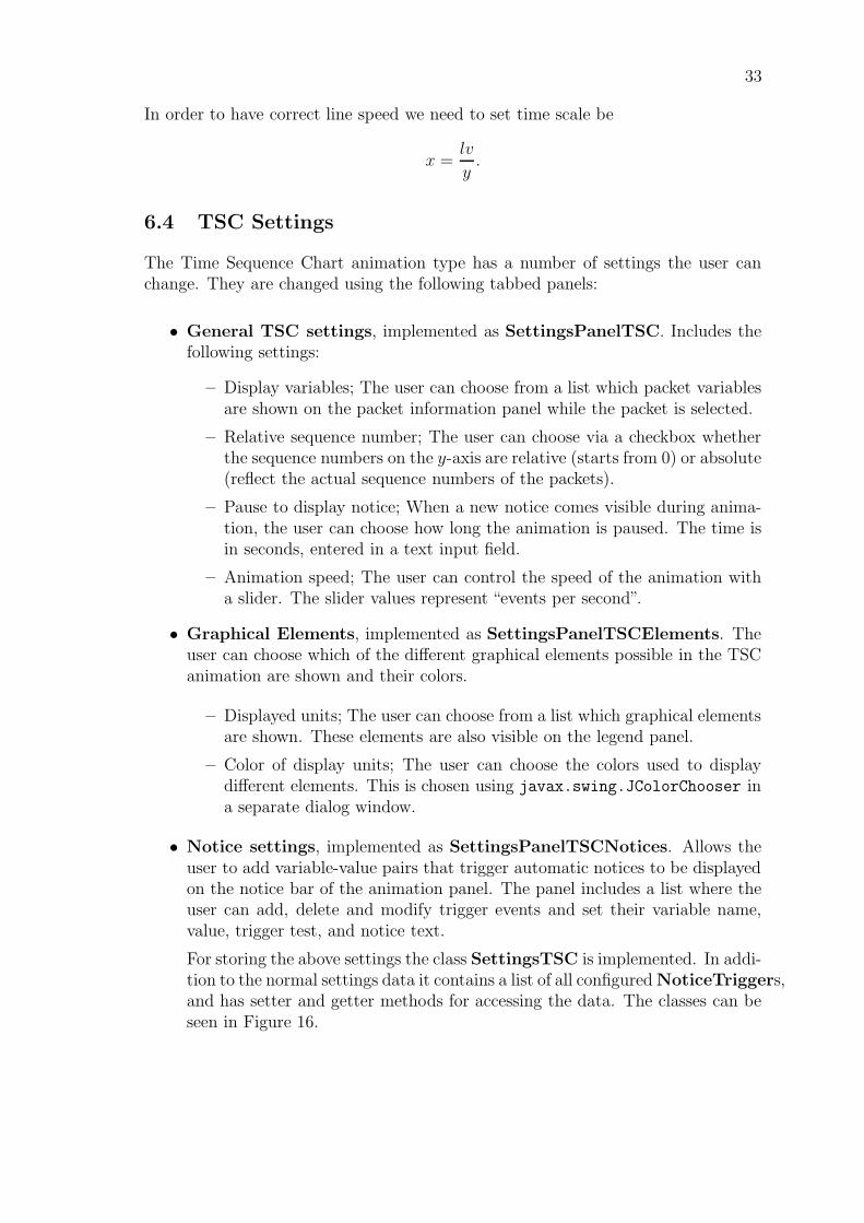
33
In order to have correct line speed we need to set time scale be
x =lv
y.
6.4 TSC Settings
The Time Sequence Chart animation type has a number of settings the user canchange. They are changed using the following tabbed panels:
• General TSC settings, implemented as SettingsPanelTSC. Includes thefollowing settings:
– Display variables; The user can choose from a list which packet variablesare shown on the packet information panel while the packet is selected.
– Relative sequence number; The user can choose via a checkbox whetherthe sequence numbers on the y-axis are relative (starts from 0) or absolute(reflect the actual sequence numbers of the packets).
– Pause to display notice; When a new notice comes visible during anima-tion, the user can choose how long the animation is paused. The time isin seconds, entered in a text input field.
– Animation speed; The user can control the speed of the animation witha slider. The slider values represent “events per second”.
• Graphical Elements, implemented as SettingsPanelTSCElements. Theuser can choose which of the different graphical elements possible in the TSCanimation are shown and their colors.
– Displayed units; The user can choose from a list which graphical elementsare shown. These elements are also visible on the legend panel.
– Color of display units; The user can choose the colors used to displaydifferent elements. This is chosen using javax.swing.JColorChooser ina separate dialog window.
• Notice settings, implemented as SettingsPanelTSCNotices. Allows theuser to add variable-value pairs that trigger automatic notices to be displayedon the notice bar of the animation panel. The panel includes a list where theuser can add, delete and modify trigger events and set their variable name,value, trigger test, and notice text.
For storing the above settings the class SettingsTSC is implemented. In addi-tion to the normal settings data it contains a list of all configured NoticeTriggers,and has setter and getter methods for accessing the data. The classes can beseen in Figure 16.
34
7 Control Signal framework
ENC
UFO
MSC DataView AnimationSequence
AnimationTimeState
−endTime: float
−nowTime: float
−listeners: ControlSignalListener[]
+getNowTime(): float
+addControlSignalListener(listener: ControlSignalListener): void
+removeControlSignalListener(listener: ControlSignalListener): void
+actionPerformed(event: jawa.awt.event.ActionEvent): void
+setStepMode(type: int): void
+setStepInterval(interval: float): void
+setTimeScale(scale: float): void
+play(): void
+pause(): void
+stepForward(): void
+stepBackward()()
+toBeginning()(): void
+toEnd(): void
ControlSignalsListener<<interface>>
+advance(step: float, nowTime: float): void
+stepTo(nowTime: float): void
+toPlayMode(): void
+toPauseMode(): void
javax.swing.JPanel ControlButtonsPanel javax.swing.JButton
for encapsulation: in that case the ’time’An instance may be used to represent time
means some arbitrary unit.
notifies
implemets java.awt.event.ActionListener
javax.swing.Timer1 1start/stop
<<call>>
<<call>> Play, Pause, StopStep forward, Step backward
has listeners
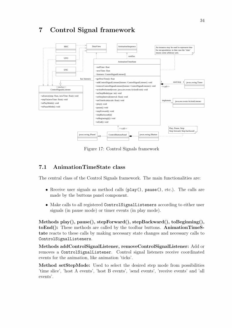
Figure 17: Control Signals framework
7.1 AnimationTimeState class
The central class of the Control Signals framework. The main functionalities are:
• Receive user signals as method calls (play(), pause(), etc.). The calls aremade by the buttons panel component.
• Make calls to all registered ControlSignalListeners according to either usersignals (in pause mode) or timer events (in play mode).
Methods play(), pause(), stepForward(), stepBackward(), toBeginning(),toEnd(): These methods are called by the toolbar buttons. AnimationTimeS-tate reacts to these calls by making necessary state changes and necessary calls toControlSignalListeners.
Methods addControlSignalListener, removeControlSignalListener: Add orremoves a ControlSignalListener. Control signal listeners receive coordinatedevents for the animation, like animation ’ticks’.
Method setStepMode: Used to select the desired step mode from possibilities’time slice’, ’host A events’, ’host B events’, ’send events’, ’receive events’ and ’allevents’.
35
Method setStepInterval: The desired step interval in physical computer clockmilliseconds for the ’ticks’ in play mode.
Method setTimeScale: Sets the time scale of the animation. Scale of 1.000 meanspresenting one second of network exchange takes ONE second of real time and scale10.000 means presenting one second of network exchange takes TEN seconds of realtime.
Other things to note:
• An AnimationTimeState object contains a javax.swing.Timer instance, whichis used to get timed animation ’ticks’ to run the animation in play mode. Foreach timer event the AnimationTimeState object gets a call on its own ac-
tionPerformed method, does the required accounting and makes subsequentcalls to all listeners.
• For all other step modes than the ’time slice’, the DataView is queried for thesize of the next tick.
• When run in Scenario mode (for presenting an animation sequence, as op-posed to Explore mode) the AnimationTimeState needs to contain an end-
Time. When the endTime is reached, the AnimatioTimeState puts itself inpause mode and calls the showNext method of the AnimationSequence object.This is a signal for the AnimationSequence to start presenting the next itemin the animation sequence.
• AnimationTimeState takes into account the actual processing rate of the timerevents. In times when the CPU load reaches 100%, it is not possible to processthe animation ticks at the target rate. In these cases the AnimationTimeStateadjusts the logical step size to reflect the actual processing speed. The logi-cal step size means the step expressed as network time in the advance(step,
nowTime) method). Because of this mechanism, the actual time spent in play-ing an animation from beginning to end depends ONLY on the length of theprotocol event data and the time scale, NOT on computer speed (within rea-sonable accuracy). However, the number of animation frames drawn duringthe presentation of the animation MAY depend on computer speed.
7.2 ControlSignalsListener interface
All animation panels need to implement the ControlSignalsListener interface.The main UI needs to register all visible animation panels as ControlSignalsLis-teners for the current AnimationTimeState object.
Method advance(step, nowTime): tells the animation panel to make an in-cremental advance from previous state to nowTime. The difference between previ-ously shown time state and nowTime is given in parameter step. If the animationpanel doesn’t need to make difference between advance operations and stepTo op-erations, this method can be implemented as just ”public void advance(float
36
step, float nowTime) stepTo(nowTime); ”. It is the responsibility of the ani-mation panel to call repaint() on itself after it has updated its state.
Method stepTo(nowTime): tells the animation panel to show the animationtime given in parameter nowTime, regardless of the previously shown state.
Method toPlayMode(): tells the animation panel that a continuing sequenceof advance(step, nowTime) calls will probably follow. (Some panels may wish todisable scrolling mode as result of this call.)
toPauseMode(): tells the animation panel that the following stepTo-calls will beresults of direct user input. (Some panels may wish to enable scrolling mode asresult of this call.)
8 Animation Sequence framework
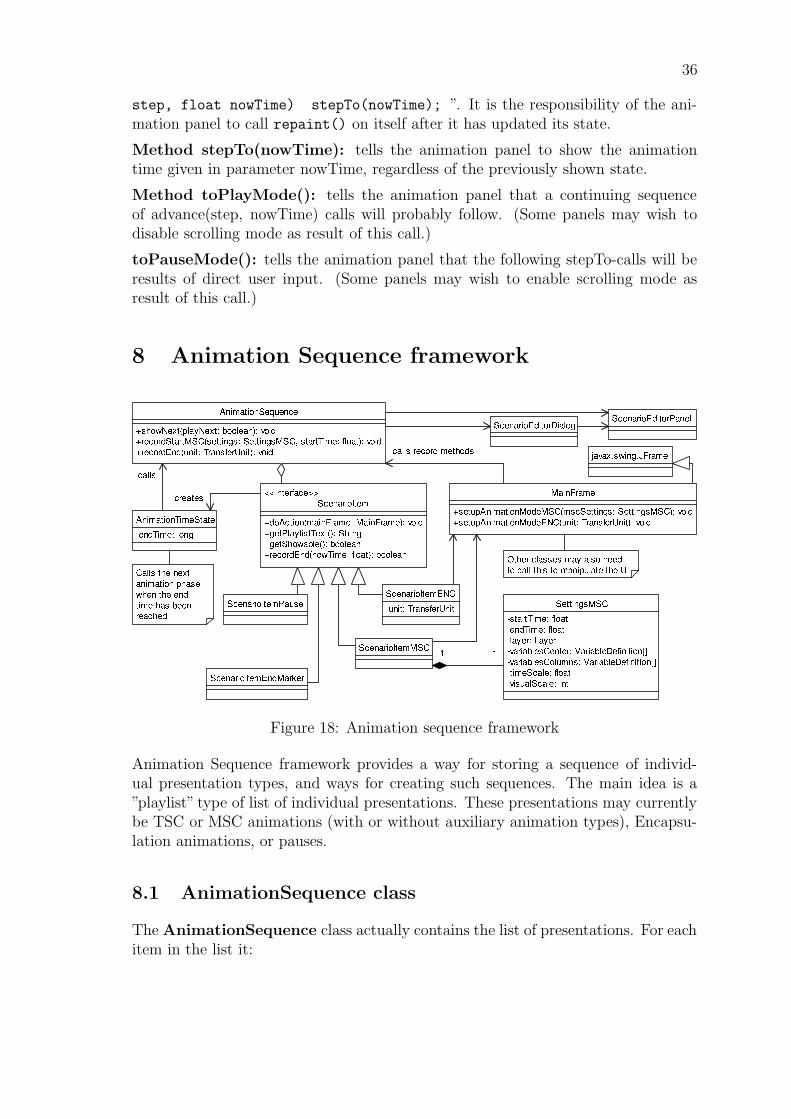
Figure 18: Animation sequence framework
Animation Sequence framework provides a way for storing a sequence of individ-ual presentation types, and ways for creating such sequences. The main idea is a”playlist” type of list of individual presentations. These presentations may currentlybe TSC or MSC animations (with or without auxiliary animation types), Encapsu-lation animations, or pauses.
8.1 AnimationSequence class
The AnimationSequence class actually contains the list of presentations. For eachitem in the list it:
37
• Creates an instance of AnimationTimeState according to the requirements ofthe item to be presented. (e.g. sets a suitable endTime)
• Calls the main UI to set the desired view mode. Gives the newly createdAnimationTimeState instance as parameter to main UI, so that it can beregistered as listener for control button signals.
• Receives a call from the AnimationTimeState instance when the endTime isreached, and initiates the presentation of the next item in the list.
8.2 ScenarioItem interface
An interface that all the items in the animation sequence need to implement. Theinterface functionality is related to providing a way to call for the item to carryout its ’action’ and to have it give the necessary information about itself for e.g.presentation in the scenario play list.
8.3 ScenarioItemMSC class
Initiates showing an MSC animation. Contains a reference to SettingsMSC objectwhich contains settings specific to the MSC animation panel.
Any settings in SettingMSC or other settings objects are created and edited throughspecific editing dialogs invoked through the main UI.
The semantics for the start time and end time for an MSC scenario item are asfollows: when the item is selected from the scenario play list, the current Anima-
tionTimeState instance is set to point to the start time of the item. When theanimation is played past the end time of the item, the AnimationTimeState willcall the AnimationSequence to select the next item in the play list, and thus endthe presentation for the previous item.
8.4 ScenarioItemTSC class
Starts the playing of a TSC animation. The implementation is essentially the sameas with the corresponding ScenarioItemMSC, described above.
8.5 ScenarioItemENC class
Instructs the MainFrame to show the encapsulation for the designated Transfer-
Unit.
38
8.6 ScenarioItemPause class
An item in the playlist that can be used to wait for user input before continuing.
8.7 Settings objects
The settings objects for animation panels, edited through specific editing dialogs andused by their respective animation panels. Currently the only two actual settingsobjects are SettingsMSC and SettingsTSC.
8.8 ScenarioEditorDialog and ScenarioEditorPanel classes
The ScenarioEditorDialog class is related only to presenting the editing widgetsinside a dialog, and how the dialog itself behaves with the MainFrame. The actualediting functionality is implemented as a separate panel to make it general so it canbe used in the UI in other ways than in its own dialog. For all editing functionality,the panel class and the AnimationSequence class communicate directly with eachother.
The ScenarioEditorPanel presents the scenario play list in an interactive listcomponent. All changes from editing will be instantly visible in the list. At all timesthe list can be used to select the desired item from the list for playing or editing. TheScenarioEditorPanel also contains the necessary buttons for inserting, deletingand editing scenario items.
8.9 Recording an animation sequence
Recording an animation sequence happens as an interaction between an Anima-
tionSequence object and the main UI. When the user wants to start recording anew animation sequence, he selects ’Scenario mode’ command from the ’Animation’menu. At that time the ScenarioEditorDialog is shown, with the ScenarioEdi-
torPanel as its contents. The dialog is non-modal, so that it is possible to operateall UI widgets while it is visible. The recording mode is toggled on and off by usingthe ’Recording mode’ toggle button in the ScenarioEditorPanel.
When the recording mode is on, whenever the user presses play, the main UI makesa method call to the recordStart method of AnimationSequence. That causesthe AnimationSequence to create a new ScenarioItem object. The exact type andsettings correspond to the active mode and settings in the main UI. The createdAnimationAction object is otherwise complete, but (in case of actions that do havea duration) it lacks the endtime.
Whenever the user changes animation settings, layer or view mode, the main UImakes method call recordEnd to the AnimationSequence. The next recordEnd
after a recordStart call is considered the end of the item being recorded. When the
39
recordStop is called, the AnimationSequence is able to complete the ScenarioItemwith the endTime information, and insert the complete object in the animationsequence list.
A summary of responsibilities for different classes regarding recording an animationsequence:
Main UI:
• Receive user input events about starting the recording, play events, modeswitches etc.
• Keep track of recording mode (on/off).
• Signal play events to AnimationSequence (params: start time, settings).
• Signal mode switch to AnimationSequence (params: end time).
AnimationSequence:
• Receive ’play’ and ’mode switch’ events from main UI.
• Create ScenarioItem objects.
• Insert ScenarioItem objects in the list that makes up the animation sequence.
• Update information in ScenarioEditorPanel.
9 Notes framework
In this section we will present a framework to work with the notes that will beshown in the different types of animation to increase the educational abilities of thesoftware.
There is only one Note class, which is used for the MSC, TSC, and ENC animationtypes. The NoteManager class acts as a container for all notes in the animations,and contains separate methods for handling the notes in the ENC, TSC, and MSCanimations.
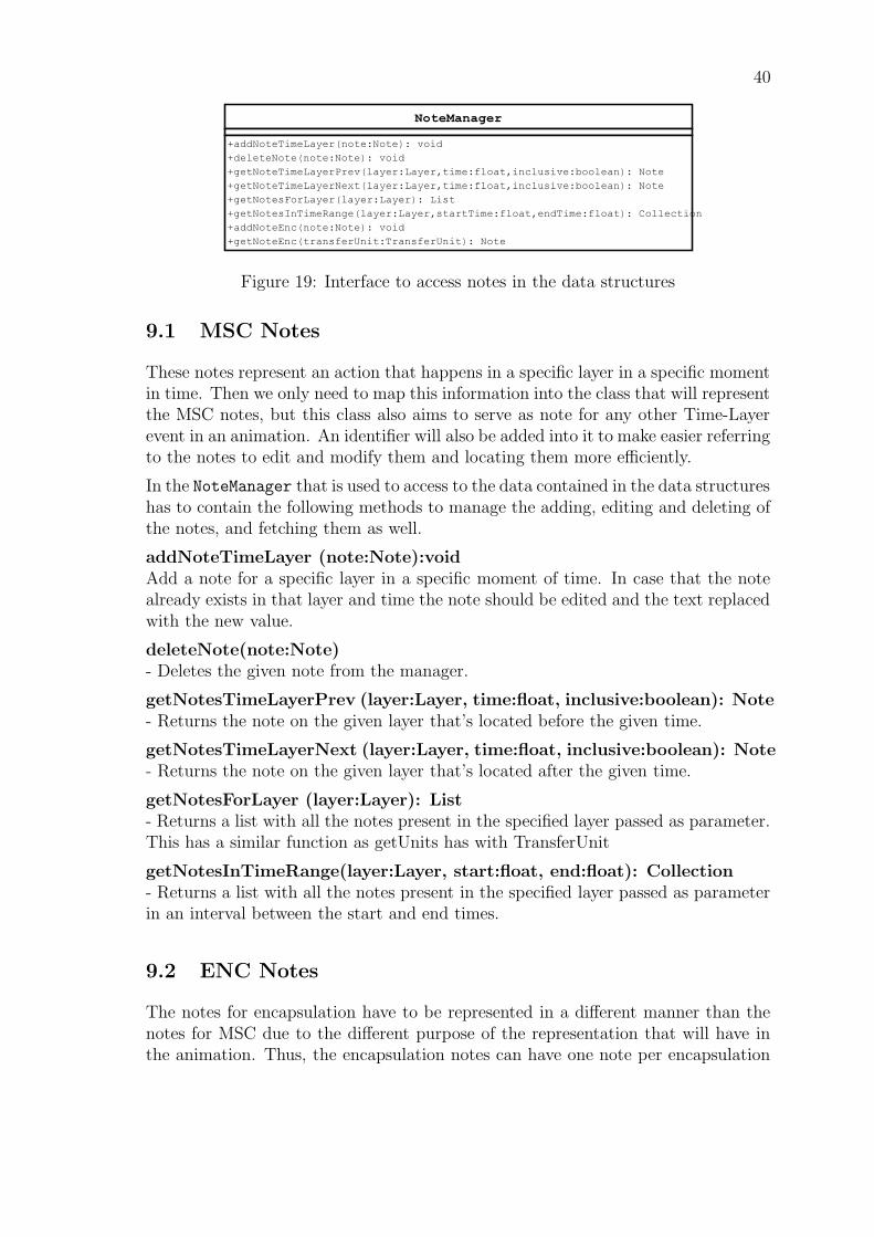
The classes for both types of notes are included into the data structures due to someassociations that need these classes with other ones present in the data structures tomake easier the access to all this data to the Control Signals framework through theNoteManager (see Figure 19). Any notes added to the NoteManager (see Figure 19)are stored along with other animation scenario data, so they’re persistent.
40
Figure 19: Interface to access notes in the data structures
9.1 MSC Notes
These notes represent an action that happens in a specific layer in a specific momentin time. Then we only need to map this information into the class that will representthe MSC notes, but this class also aims to serve as note for any other Time-Layerevent in an animation. An identifier will also be added into it to make easier referringto the notes to edit and modify them and locating them more efficiently.
In the NoteManager that is used to access to the data contained in the data structureshas to contain the following methods to manage the adding, editing and deleting ofthe notes, and fetching them as well.
addNoteTimeLayer (note:Note):voidAdd a note for a specific layer in a specific moment of time. In case that the notealready exists in that layer and time the note should be edited and the text replacedwith the new value.
deleteNote(note:Note)- Deletes the given note from the manager.
getNotesTimeLayerPrev (layer:Layer, time:float, inclusive:boolean): Note- Returns the note on the given layer that’s located before the given time.
getNotesTimeLayerNext (layer:Layer, time:float, inclusive:boolean): Note- Returns the note on the given layer that’s located after the given time.
getNotesForLayer (layer:Layer): List- Returns a list with all the notes present in the specified layer passed as parameter.This has a similar function as getUnits has with TransferUnit
getNotesInTimeRange(layer:Layer, start:float, end:float): Collection- Returns a list with all the notes present in the specified layer passed as parameterin an interval between the start and end times.
9.2 ENC Notes
The notes for encapsulation have to be represented in a different manner than thenotes for MSC due to the different purpose of the representation that will have inthe animation. Thus, the encapsulation notes can have one note per encapsulation
41
tree and this note is shown at the end or during the ENC animation.
This note for encapsulation should be in a different class as is information containedin the data structures, but represents a different concept than the information com-ing from the protocol events and must be separated from them.
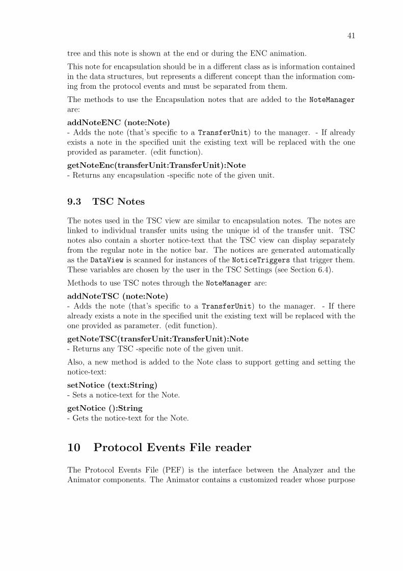
The methods to use the Encapsulation notes that are added to the NoteManager
are:
addNoteENC (note:Note)- Adds the note (that’s specific to a TransferUnit) to the manager. - If alreadyexists a note in the specified unit the existing text will be replaced with the oneprovided as parameter. (edit function).
getNoteEnc(transferUnit:TransferUnit):Note- Returns any encapsulation -specific note of the given unit.
9.3 TSC Notes
The notes used in the TSC view are similar to encapsulation notes. The notes arelinked to individual transfer units using the unique id of the transfer unit. TSCnotes also contain a shorter notice-text that the TSC view can display separatelyfrom the regular note in the notice bar. The notices are generated automaticallyas the DataView is scanned for instances of the NoticeTriggers that trigger them.These variables are chosen by the user in the TSC Settings (see Section 6.4).
Methods to use TSC notes through the NoteManager are:
addNoteTSC (note:Note)- Adds the note (that’s specific to a TransferUnit) to the manager. - If therealready exists a note in the specified unit the existing text will be replaced with theone provided as parameter. (edit function).
getNoteTSC(transferUnit:TransferUnit):Note- Returns any TSC -specific note of the given unit.
Also, a new method is added to the Note class to support getting and setting thenotice-text:
setNotice (text:String)- Sets a notice-text for the Note.
getNotice ():String- Gets the notice-text for the Note.
10 Protocol Events File reader
The Protocol Events File (PEF) is the interface between the Analyzer and theAnimator components. The Animator contains a customized reader whose purpose
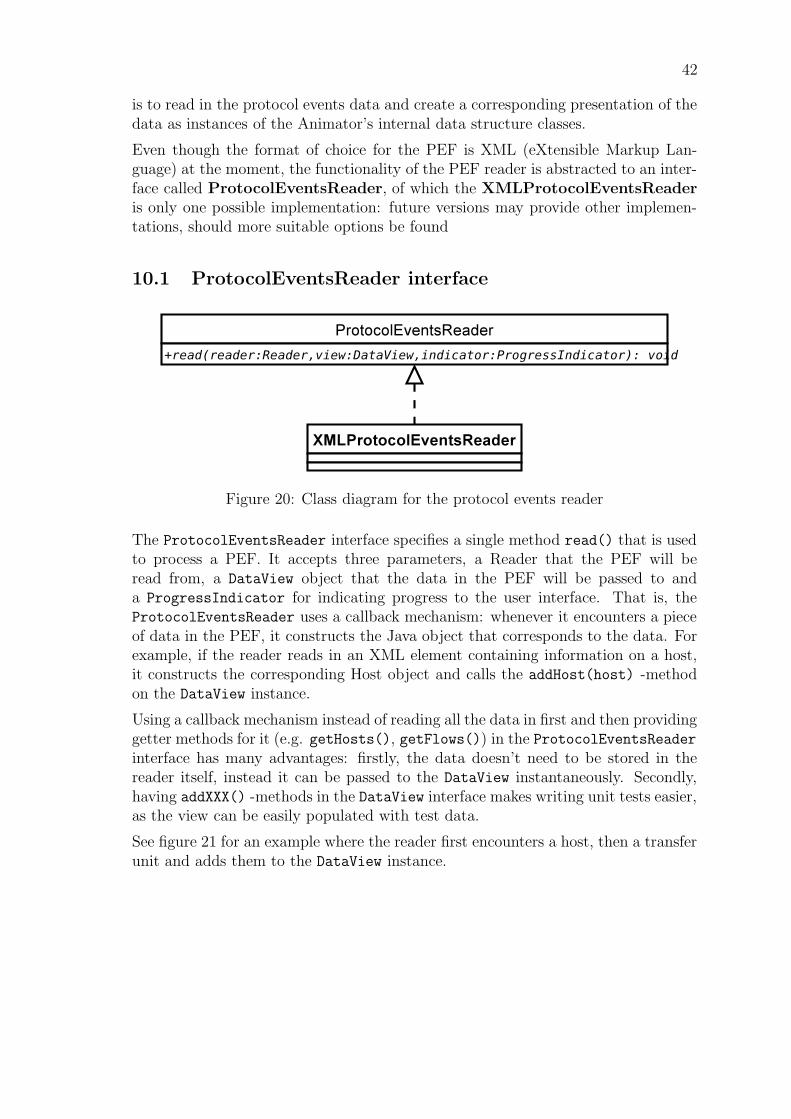
42
is to read in the protocol events data and create a corresponding presentation of thedata as instances of the Animator’s internal data structure classes.
Even though the format of choice for the PEF is XML (eXtensible Markup Lan-guage) at the moment, the functionality of the PEF reader is abstracted to an inter-face called ProtocolEventsReader, of which the XMLProtocolEventsReaderis only one possible implementation: future versions may provide other implemen-tations, should more suitable options be found
10.1 ProtocolEventsReader interface
Figure 20: Class diagram for the protocol events reader
The ProtocolEventsReader interface specifies a single method read() that is usedto process a PEF. It accepts three parameters, a Reader that the PEF will beread from, a DataView object that the data in the PEF will be passed to anda ProgressIndicator for indicating progress to the user interface. That is, theProtocolEventsReader uses a callback mechanism: whenever it encounters a pieceof data in the PEF, it constructs the Java object that corresponds to the data. Forexample, if the reader reads in an XML element containing information on a host,it constructs the corresponding Host object and calls the addHost(host) -methodon the DataView instance.
Using a callback mechanism instead of reading all the data in first and then providinggetter methods for it (e.g. getHosts(), getFlows()) in the ProtocolEventsReaderinterface has many advantages: firstly, the data doesn’t need to be stored in thereader itself, instead it can be passed to the DataView instantaneously. Secondly,having addXXX() -methods in the DataView interface makes writing unit tests easier,as the view can be easily populated with test data.
See figure 21 for an example where the reader first encounters a host, then a transferunit and adds them to the DataView instance.
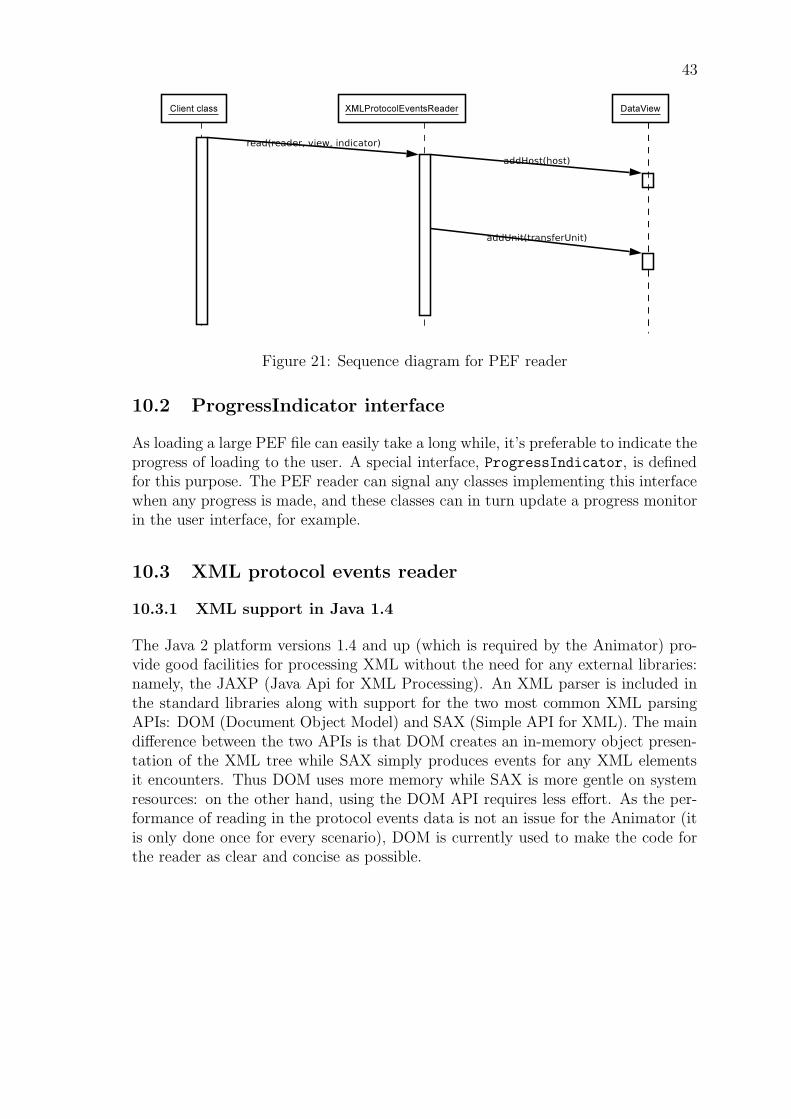
43
Figure 21: Sequence diagram for PEF reader
10.2 ProgressIndicator interface
As loading a large PEF file can easily take a long while, it’s preferable to indicate theprogress of loading to the user. A special interface, ProgressIndicator, is definedfor this purpose. The PEF reader can signal any classes implementing this interfacewhen any progress is made, and these classes can in turn update a progress monitorin the user interface, for example.
10.3 XML protocol events reader
10.3.1 XML support in Java 1.4
The Java 2 platform versions 1.4 and up (which is required by the Animator) pro-vide good facilities for processing XML without the need for any external libraries:namely, the JAXP (Java Api for XML Processing). An XML parser is included inthe standard libraries along with support for the two most common XML parsingAPIs: DOM (Document Object Model) and SAX (Simple API for XML). The maindifference between the two APIs is that DOM creates an in-memory object presen-tation of the XML tree while SAX simply produces events for any XML elementsit encounters. Thus DOM uses more memory while SAX is more gentle on systemresources: on the other hand, using the DOM API requires less effort. As the per-formance of reading in the protocol events data is not an issue for the Animator (itis only done once for every scenario), DOM is currently used to make the code forthe reader as clear and concise as possible.
44
10.3.2 Implementation using the JAXP classes
The XML-based events reader can obtain a DOM parser using the classjavax.xml.parsers.DocumentBuilderFactory. The parser can then be used toparse the PEF to an in-memory XML tree, which can then be processed to createinstances of the internal data structures of the Animator.
Classes for accessing the actual DOM XML tree are located in a package calledorg.w3c.dom. For example, each element (tag) in the document is represented asa org.w3c.dom.Element in the object tree.
10.4 PEF file enhancements
The new TSC component requires some more information, which is currently notavailable from PEF files. Since this project does not include extending the Analyzerprogram, required information must be added into PEF files by hand.
10.4.1 SACK
The Selective Acknowledgment (SACK) information is not present in current Analyzator-generated PEF files. The Animator will assume that the sack information can beread from TCP layer unit_sent -event from a sack variable. The variable valueformat will be as follows: seqnoi − seqnoj, seqnok − seqnol, . . .
For example: 100-105,340-350,360-363 (white space doesn’t matter). More informa-tion on how SACK works can be found from http://rfc.net/rfc2018.html.
10.4.2 Transfer unit size display
The vertical axis of TSC view shows TCP sequence numbers, but also representsthe amount of data sent in bytes. This does not include header size information butonly payload data size. Since the TransferUnit objects created from TCP protocolevents do not contain data size information, size must be calculated using the IPlayer TransferUnit objects referenced by TCP transfer units.
The IP layer unit_sent -events of current PEF files contain a tot_len variable,which represents the total length of a single IP packet. Also the TCP layer eventscontain a data_offset variable, which represents the length of a TCP header in32-bit words. To be able to calculate the TCP transfer unit data length, the PEFfiles should contain also an IP packet header length information. This informationis currently missing from Analyzator-generated PEF files.
The TSC component will query the TPC segment’s payload size from TransferUnit
using method getPayloadSize. This method, however, assumes that the IP layerevents contain an ihl variable, which is a standard IP header field representing thelength of a IP header in 32-bit words. Since the current PEF files do not contain
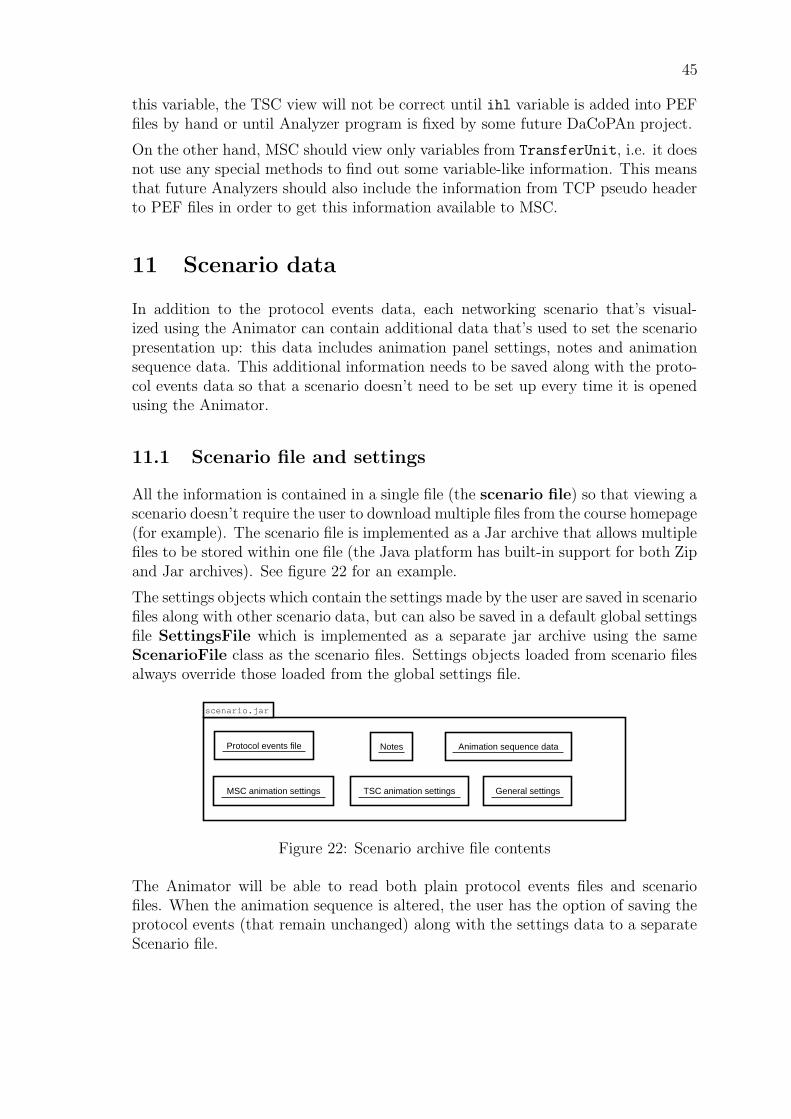
45
this variable, the TSC view will not be correct until ihl variable is added into PEFfiles by hand or until Analyzer program is fixed by some future DaCoPAn project.
On the other hand, MSC should view only variables from TransferUnit, i.e. it doesnot use any special methods to find out some variable-like information. This meansthat future Analyzers should also include the information from TCP pseudo headerto PEF files in order to get this information available to MSC.
11 Scenario data
In addition to the protocol events data, each networking scenario that’s visual-ized using the Animator can contain additional data that’s used to set the scenariopresentation up: this data includes animation panel settings, notes and animationsequence data. This additional information needs to be saved along with the proto-col events data so that a scenario doesn’t need to be set up every time it is openedusing the Animator.
11.1 Scenario file and settings
All the information is contained in a single file (the scenario file) so that viewing ascenario doesn’t require the user to download multiple files from the course homepage(for example). The scenario file is implemented as a Jar archive that allows multiplefiles to be stored within one file (the Java platform has built-in support for both Zipand Jar archives). See figure 22 for an example.
The settings objects which contain the settings made by the user are saved in scenariofiles along with other scenario data, but can also be saved in a default global settingsfile SettingsFile which is implemented as a separate jar archive using the sameScenarioFile class as the scenario files. Settings objects loaded from scenario filesalways override those loaded from the global settings file.
scenario.jar
Protocol events file Notes
MSC animation settings
Animation sequence data
TSC animation settings General settings
Figure 22: Scenario archive file contents
The Animator will be able to read both plain protocol events files and scenariofiles. When the animation sequence is altered, the user has the option of saving theprotocol events (that remain unchanged) along with the settings data to a separateScenario file.
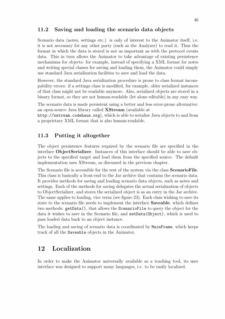
46
11.2 Saving and loading the scenario data objects
Scenario data (notes, settings etc.) is only of interest to the Animator itself, i.e.it is not necessary for any other party (such as the Analyzer) to read it. Thus theformat in which the data is stored is not as important as with the protocol eventsdata. This in turn allows the Animator to take advantage of existing persistencemechanisms for objects: for example, instead of specifying a XML format for notesand writing special classes for saving and loading them, the Animator could simplyuse standard Java serialization facilities to save and load the data.
However, the standard Java serialization procedure is prone to class format incom-pability errors: if a settings class is modified, for example, older serialized instancesof that class might not be readable anymore. Also, serialized objects are stored in abinary format, so they are not human-readable (let alone editable) in any easy way.
The scenario data is made persistent using a better and less error-prone alternative:an open-source Java library called XStream (available athttp://xstream.codehaus.org), which is able to serialize Java objects to and froma proprietary XML format that is also human-readable.
11.3 Putting it altogether
The object persistence features required by the scenario file are specified in theinterface ObjectSerializer. Instances of this interface should be able to save ob-jects to the specified target and load them from the specified source. The defaultimplementation uses XStream, as discussed in the previous chapter.
The Scenario file is accessible for the rest of the system via the class ScenarioFile.This class is basically a front-end to the Jar archive that contains the scenario data.It provides methods for saving and loading scenario data objects, such as notes andsettings. Each of the methods for saving delegates the actual serialization of objectsto ObjectSerializer, and stores the serialized object is as an entry in the Jar archive.The same applies to loading, vice versa (see figure 23). Each class wishing to save itsstate to the scenario file needs to implement the interface Saveable, which definestwo methods: getData(), that allows the ScenarioFile to query the object for thedata it wishes to save in the Scenario file, and setData(Object), which is used topass loaded data back to an object instance.
The loading and saving of scenario data is coordinated by MainFrame, which keepstrack of all the Saveable objects in the Animator.
12 Localization
In order to make the Animator universally available as a teaching tool, its userinterface was designed to support many languages, i.e. to be easily localized.
47
Figure 23: Scenario file class diagram
12.1 The Localization class
The localization functionality of the Animator is centralized in one central class, Lo-calization. At startup, the Localization class loads the property file locales.propertiesfrom the classpath. This file contains a list of all the available translations for theAnimator. For each available language, the localized strings are stored in a filecalled dacopanxx.properties, where xx is a two-digit language code recognizedby the java.util.Locale class. As English is the default language of the Animator,strings localized to English are stored in the file dacopan.properties. The standardJava class ResourceBundle takes care of resolving take localized strings from theproperty files.
The Localization class provides the method getString(String key) for retrievingthe localized strings from the property files. A localized string is not restricted tostatic text only. It can contain placeholders for variables in the format supported bythe class java.text.MessageFormat. To populate a string with variables, the methodgetString(String key, Object[] params) can be used.
For the purposes of listing the available languages in the user interface, the methodgetAvailableLanguages() can be used. To change the active language, use themethod setCurrentLanguage(Localization.Language). Localization.Languageis a simple inner class that wraps the name of a language and the Locale it represents.The selection of a language is persistent: it is saved using the Java preferencesframework (see package java.util.prefs).
References
1 DaCoPAn Software Engineering project, Design: Animator. Re-lease 1.0. Universities of Helsinki and Petrozavodsk, 2004.
Appendix A. Glossary
The following are definitions, acronyms and abbreviations used in this document.
ACK packet: ACK packets are used to acknowledge the receipt of a packet inthe Transmission Control Protocol (TCP). They are used by both ends of theconnection to move in between states, and are the basis of TCP’s reliability.
Analyzer: A module of the DaCoPAn project. It reads and analyzes packet tracefiles and produces a protocol events file (PEF) as its output.
Animator: A module of the DaCoPAn project. It reads protocol events files (PEF)and scenario files (SCE files), and animates the protocol exchanges using var-ious parameters. Its main use is as a teaching tool to instruct students onprotocol basics found in the protocol event file.
balloon: See notices.
DaCoPAn: DaCoPAn stands for visualization of Data Communication Protocolthrough Animation.
disappearing unit: See dropped packet.
dropped packet: A unit which has vanished during the course of network trans-mission.
drawing area: The section of the MSC and TSC animation views where the actualnetwork data is visualized and animated.
ENC: An abbreviation for the Encapsulation view. The Encapsulation (ENC)panel is one of four animation views which the software can display.
event: The occurance of a protocol exchange. For example, an event can be thesending or receiving of a unit.
header variable: Various TCP or other network layer variables which are con-tained in the transfer unit header fields.
MSC: An abbreviation for the Message Sequence Chart view. The Message Se-quence Chart (MSC) panel is one of four animation views which the softwarecan display.
notices: Notices are automatically generated by the TSC view based on variousevents in the PEF file and displayed inside small rectangles in the notice bar.
notes: Notes are free format textual information that can be added, edited andremoved freely by the user. Both the MSC and TSC animation views containa separate notes panel.
PEF: The abbreviation stands for Protocol Events File, and is synonymous withthe term PEF file and PEF files, as used throughout the document. It is anoutput file generated by the Analyzer and read by the Animator. It containsdata about the network traffic that will be animated by the Animator.
progress line: The blue horizontal line in the MSC panel, which scrolls down theview as the animation proceeds and reveals transpiring events as they unfold.
SACK: Selective Acknowledgment. An optional TCP feature which allows thereceiver to specify which segments it has received and which ones require re-transmission.
scenario file: A native file written and read by the Animator. It contains all thedata from a protocol events file and additional data related to how the scenariocan be presented to the user, including notes and breakpoints.
SCE file(s): See scenario file.
sequence number: Every segment of data sent over a TCP connection has a se-quence number. The sequence number is the number of the first data byte inthe segment.
SEQNO: See sequence number.
TSC: An abbreviation for the Time Sequence Chart animation view. The TimeSequence Chart (TSC) panel is one of four animation views which the softwarecan display.
UFO: An abbreviation for the Unit Flow Orchestration view. The Unit Flow Or-chestration (UFO) panel is one of four animation views which the software candisplay.
unit: A transfer unit, which refers to all logical units that are transferred regardlessof network layer. Thus, a unit can be an IP packet, a TCP segment or anapplication layer message.
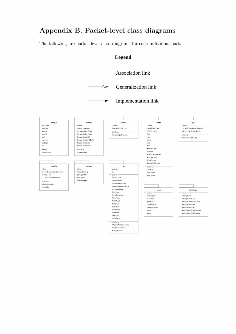
Appendix B. Packet-level class diagrams
The following are packet-level class diagrams for each individual packet.
Generalization link
Association link
Implementation link
Legend
classes
DrawingArea
MainPanel
NoteBar
LegendPanel
PacketInfoPanel
Xaxis
Yaxis
ui.tsc
classes
SettingsPanel
SettingsPanelLayer
SettingsPanelPerformance
SettingsPanelScale
SettingsPanelTSC
SettingsPanelTSCNotices
SettingsPanelTSCElements
ui.settings
animseq
contsig
model
pef
scenario
settings
ui
packages classes
AnimationSequence
ScenarioEditorDialog
ScenarioEditorPanel
classes
AnimationTimeState
classes
classes
ProtocolEventsDataException
classes packages
tsc
classes
dacopan animseq contsig model pef
uisettingsscenario
ScenarioItemENC
ScenarioItemEndMarker
ScenarioItemMSC
ScenarioItemPause
DefaultDataView
ENCTreeModel
Flow
Host
Layer
Link
Note
NoteManager
Protocol
ScenarioStepIterator
StaticVariable
TransferUnit
VariableDefinition
XMLProtocolEventsReader
ScenarioFile
InvalidScenarioFileException
XStreamObjectSerializer CalcYCoord
ChannelPanel
DaCoPAnFileFilter
DialogProgressIndicator
EditNoteDialog
ENCPanel
FileInformation
MainFrame
MSCPanel
NotePanel
classes
Localization ScenarioItem
interfaces
ControlSignalsListener
interfaces
Saveable
ObjectSerializer
interfaces
classes
GeneralSettings
StepIterator
Identifiable
DataView
interfaces
ProtocolEventsReader
interfaces
SettingsMSC
NoticeTrigger
SettingsTSC
StatusBar
TimePanel
TitlePanel
UFOPanel
UserInterface
interfaces
AbstractAnimationPanel
ProgressIndicator
SwingWorker
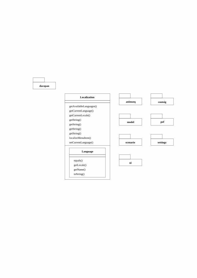
Localization
getAvailableLanguages()
getCurrentLanguage()
getCurrentLocale()
getString()
getString()
getString()
getString()
localizeMenuItem()
setCurrentLanguage()
Language
equals()
getLocale()
getName()
toString()
dacopan
animseq contsig
model pef
scenario settings
ui
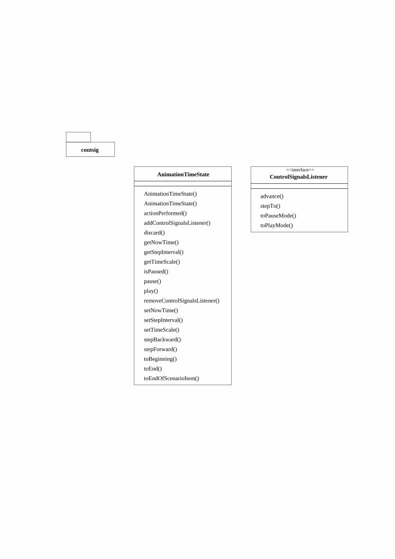
AnimationTimeState
AnimationTimeState()
AnimationTimeState()
actionPerformed()
addControlSignalsListener()
discard()
getNowTime()
getStepInterval()
getTimeScale()
advance()
stepTo()
toPauseMode()
toPlayMode()
isPaused()
pause()
play()
removeControlSignalsListener()
setNowTime()
setStepInterval()
setTimeScale()
stepBackward()
stepForward()
toBeginning()
toEnd()
toEndOfScenarioItem()
<<interface>>
contsig
ControlSignalsListener
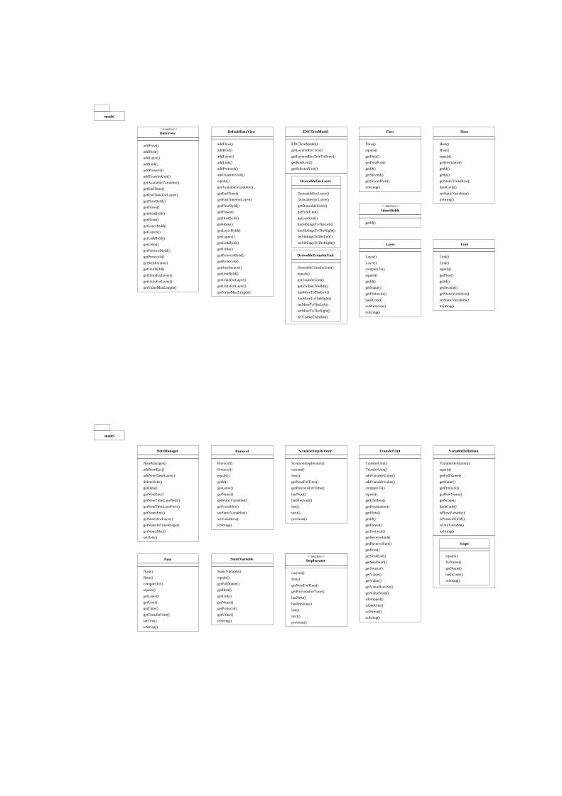
Identifiable<<interface>>
getId()
Layer
Layer()
Layer()
compareTo()
equals()
getId()
getName()
getProtocols()
hashCode()
setProtocols()
toString()
Link
Link()
Link()
equals()
getFirst()
getId()
getSecond()
getStaticVariables()
setStaticVariables()
toString()
addFlow()
addHost()
addLayer()
addLink()
addProtocol()
addTransferUnit()
equals()
ENCTreeModel()
getLayeredEncTree()
getLayeredEncTreeToDraw()
getRootUnit()
getSelectedUnit()
getAvailableVariables()
getEndTime()
getEndTimeForLayer()
getFlowById()
getFlows()
getHostById()
getLayerById()
getHosts()
getLayers()
getLinkById()
getLinks()
getValueMaxLength()
getUnitsForLayer()
getUnitsForLayer()
getUnitById()
getStepIterator()
getProtocols()
getProtocolById()
DrawableEncLayer
DrawableEncLayer()
getDrawableUnits()
DrawableEncLayer()
getFirstUnit()
getLastUnit()
hasSiblingsToTheLeft()
hasSiblingsToTheRight()
setSiblingsToTheLeft()
setSiblingsToTheRight()
DrawableTransferUnit()
equals()
getTransferUnit()
getVisibleChildIds()
hasMoreToTheLeft()
hasMoreToTheRight()
setMoreToTheLeft()
setMoreToTheRight()
setVisibleChildIds()
DrawableTransferUnit
Flow
Flow()
equals()
getFirst()
getFirstPort()
getId()
getSecond()
getSecondPort()
toString()
Host()
Host()
equals()
getId()
getHostname()
toString()
setStaticVariables()
hashCode()
getStaticVariables()
getIp()
model
addFlow()
addHost()
addLayer()
addLink()
addProtocol()
addTransferUnit()
getAvailableVariables()
getEndTime()
getEndTimeForLayer()
getFlowById()
getFlows()
getHostById()
getHosts()
getLayerById()
getLayers()
getLinkById()
getLinks()
getProtocolById()
getProtocols()
getStepIterator()
getUnitById()
getUnitsForLayer()
getUnitsForLayer()
getValueMaxLength()
DataView<<interface>>
DefaultDataView ENCTreeModel Host
TransferUnit
TransferUnit()
TransferUnit()
addVariableValue()
addVariableValue()
compareTo()
equals()
getChildren()
getDestination()
getFlow()
getId()
getParent()
getProtocol()
getReceiveEnd()
getReceiveStart()
getRoot()
getSendEnd()
getSendStart()
getSource()
getValue()
getValue()
getValueReceive()
getValueSend()
isDropped()
isOneUnit()
setParent()
toString()
VariableDefinition
VariableDefinition()
equals()
getFullName()
getName()
getProtocol()
getRawName()
getScope()
hashCode()
isFlowVariable()
isProtocolField()
isUnitVariable()
toString()
Scope
equals()
forName()
getName()
hashCode()
toString()
StaticVariable
StaticVariable()
equals()
getFullName()
getHost()
getLink()
getName()
getProtocol()
getValue()
toString()
model
NoteManager Protocol ScenarioStepIterator
NoteManager()
addNoteEnc()
addNoteTimeLayer()
deleteNote()
getData()
getNoteEnc()
getNoteTimeLayeNext()
getNoteTimeLayePrev()
getNotesEnc()
getNotesForLayer()
getNotesInTimeRange()
getNotesMsc()
setData()
Protocol()
Protocol()
equals()
getId()
getLayer()
getName()
getStaticVariables()
getVariables()
setStaticVariables()
setVariables()
toString()
ScenarioStepIterator()
current()
first()
getNextForTime()
getPreviousForTime()
hasNext()
hasPrevious()
last()
next()
previous()
Note
Note()
Note()
compareTo()
equals()
getLayer()
getText()
getTime()
getTransferUnit()
setText()
toString()
StepIterator<<interface>>
current()
first()
getNextForTime()
getPreviousForTime()
hasNext()
hasPrevious()
last()
next()
previous()
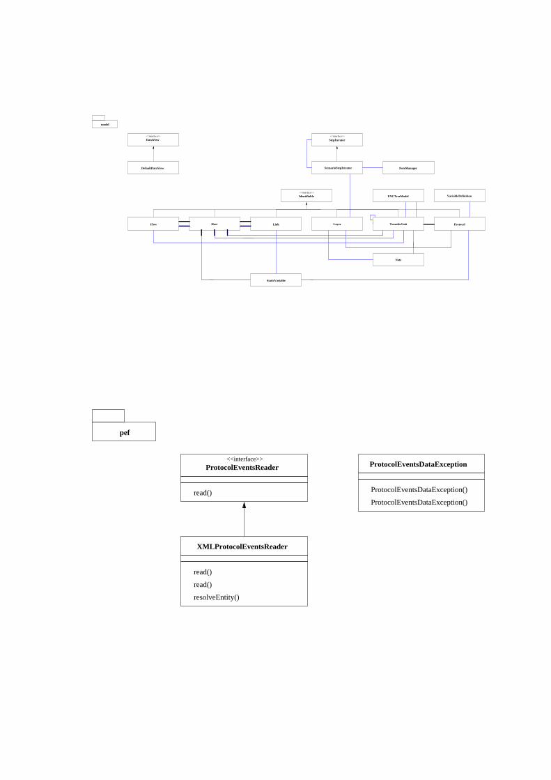
Host Link LayerFlow
Identifiable<<interface>>
ScenarioStepIterator
StepIterator<<interface>>
TransferUnit Protocol
StaticVariable
NoteManager
ENCTreeModel VariableDefinition
DataView<<interface>>
DefaultDataView
model
Note
pef
<<interface>>
ProtocolEventsReader ProtocolEventsDataException
read()
XMLProtocolEventsReader
resolveEntity()
read()
read()
ProtocolEventsDataException()
ProtocolEventsDataException()
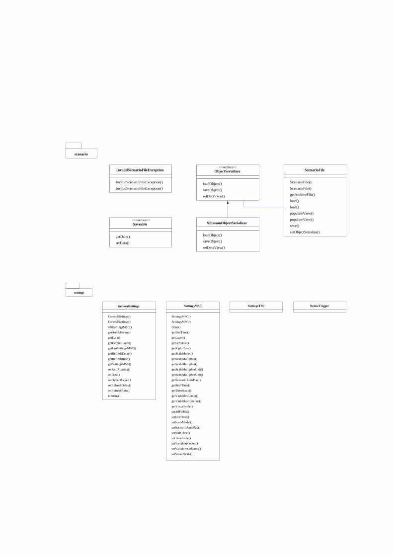
<<interface>>
Saveable
getData()
setData()
ScenarioFile
ScenarioFile()
getArchiveFile()
load()
load()
populateView()
populateView()
save()
setObjectSerialize()
ScenarioFile()
InvalidScenarioFileException
InvalidScenarioFileException()
InvalidScenarioFileException()
scenario
ObjectSerializer<<interface>>
setDataView()
saveObject()
loadObject()
XStreamObjectSerializer
loadObject()
saveObject()
setDataView()
settings
GeneralSettings
GeneralSettings()
addSettingsMSC()
getAntiAliasing()
getData()
getDefaultLayer()
getListSettingsMSC()
getRefreshDelay()
getRefreshRate()
getSettingsMSC()
setAntiAliasing()
setData()
setDefaultLayer()
setRefreshDelay()
setRefreshRate()
toString()
GeneralSettings()
SettingsMSC
SettingsMSC()
SettingsMSC()
clone()
getEndTime()
getLayer()
getLeftHost()
getRightHost()
getScaleModel()
getScaleMultiplier()
getScaleMultiplier()
getScaleMultiplierUnit()
getScaleMultiplierUnit()
getScenarioAutoPlay()
getStartTime()
getTimeScale()
getVariablesCenter()
getVariablesColumns()
getVisualScale()
setAllFields()
setEndTime()
setScaleModel()
setScenarioAutoPlay()
setStartTime()
setTimeScale()
setVariablesCenter()
setVariablesColumns()
setVisualScale()
SettingsTSC NoticeTrigger
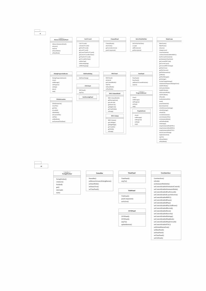
DaCoPAnFileFilter
DaCoPAnFileFilter()
accept()
addExtension()
getDescription()
ChannelPanel
ChannelPanel()
drawUnits()
getCurrentlyActive()
paintComponent()
CalcYCoord()
calculateYCoord()
getFirstYCoord()
getLastYCoord()
getLinearTimeForYCoord()
getLinearYCoordForTime()
getTimeForYCoord()
getYCoordForTime()
setMaxGap()
setMaxStepping()
setMinStepping()
CalcYCoordAbstractAnimationPanel<<interface>>
AbstractAnimationPanel()
advance()
stepTo()
toPauseMode()
toPlayMode()
ui
EditNoteDialog
EditNoteDialog()
ENCPanel
ENCPanel()
stepTo()
EncDrawingPanel
NotePanel
NotePanel()
NotePanel()
addNoteToCurrentPosition()
stepTo()
MSCPanel()
advance()
getColumnModel()
stepTo()
toPauseMode()
toPlayMode()
MSCPanel
MSCColumnModel
MSCColumnModel()
getDrawingArea()
getLeftCols()
getNotesCol()
getRightCols()
getTotalWidth()
toString()
MSCColumn
MSCColumn()
getLeftEdge()
getRightEdge()
getVariable()
getWidth()
toString()
ProgressIndicator<<interface>>
close()
setMessage()
setProgress()
setStep()
step()
NoopIndicator
close()
setMessage()
setProgress()
setStep()
step()
DialogProgressIndicator
DialogProgressIndicator()
close()
setMessage()
setProgress()
setStep()
show()
step()
FileInformation
FileInformation()
closeFile()
getFile()
isLoaded()
isModified()
isScenarioFile()
setFile()
setModified()
useGeneratedTestData()
MainFrame()
MainFrame()
advance()
changeLayer()
closeAnimation()
continueAnimationModeMSC()
fastForwardAnimation()
getAnimationTimeState()
getCurrentLayer()
getCurrentENCUnit()
getCurrentMSCSettings()
getDataView()
getFileChooser()
getFileInformation()
getMode()
getNoteManager()
getSettings()
invokeChangeSettings()
isAnimationSequenceDialogActive()
MainFrame
isInENCMode()
isInExploreMode()
isInMSCMode()
isInScenarioMode()
isInTSCMode()
isPaused()
loadAnimationFile()
main()
pauseAnimation()
playAnimation()
refreshScenarioSettings()
refreshSettings()
refreshUI()
rewindAnimation()
saveAnimationFile()
setAnimationMode()
setFileModified()
setSettings()
setupAnimationModeENC()
setupAnimationModeMSC()
setupAnimationModeTSC()
showScenarioDialog()
stepInAnimation()
stepTo()
toPauseMode()
toPlayMode()
<<interface>>SwingWorker
SwingWorker()
construct()
finished()
get()
interrupt()
start()
StatusBar
StatusBar()
setRestoreScenarioDialogButton()
setStateMode()
setStatusText()
setTimePanel()
stepTo()
TimePanel()
TimePanel
TitlePanel()
paintComponent()
setActive()
TitlePanel
UserInterface()
refresh()
setAnimatorModeInfo()
setControlsEnabledAnimationControl()
setControlsEnabledAnimatorMode()
setControlsEnabledFastForward()
setControlsEnabledLayerSelection()
setControlsEnabledMSC()
setControlsEnabledPause()
setControlsEnabledPlay()
setControlsEnabledPlayAndPause()
setControlsEnabledRewind()
setControlsEnabledSave()
setControlsEnabledSaveAs()
setControlsEnabledSettings()
setControlsEnabledStepBack()
setControlsEnabledStepForward()
setControlsEnabledTSC()
setDefaultButtonFont()
setMainPanel()
setNotePanel()
setTimePanel()
setUfoPanel()
UserInterface
UFOPanel()
UFOPanel()
stepTo()
updateButtons()
UFOPanel
ui
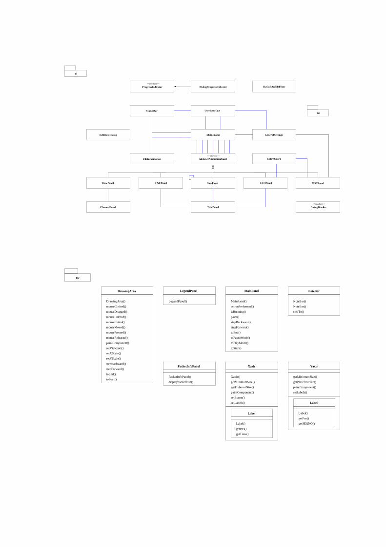
CalcYCoord
DaCoPAnFileFilter
EditNoteDialog
tsc
MainFrame
AbstractAnimationPanel<<interface>>
TimePanel NotePanel MSCPanelUFOPanelENCPanel
TitlePanelChannelPanel
StatusBar UserInterface
FileInformation
SwingWorker
ProgressIndicator<<interface>>
DialogProgressIndicator
<<interface>>
ui
GeneralSettings
tsc
LegendPanel
LegendPanel()
MainPanel
MainPanel()
actionPerformed()
isRunning()
paint()
stepBackward()
stepForward()
toEnd()
toPauseMode()
toPlayMode()
toStart()
NoteBar
NoteBar()
NoteBar()
stepTo()
Xaxis
Xaxis()
getMinimumSize()
getPreferredSize()
paintComponent()
setExtent()
setLabels()
Label
getPos()
Label()
getTime()
Yaxis
getMinimumSize()
getPreferredSize()
paintComponent()
setLabels()
Label
Label()
getPos()
getSEQNO()
PacketInfoPanel
PacketInfoPanel()
displayPacketInfo()
DrawingArea
DrawingArea()
mouseClicked()
mouseDragged()
mouseEntered()
mouseExited()
mouseMoved()
mousePressed()
mouseReleased()
paintComponent()
setViewport()
setXScale()
setYScale()
stepBackward()
stepForward()
toEnd()
toStart()
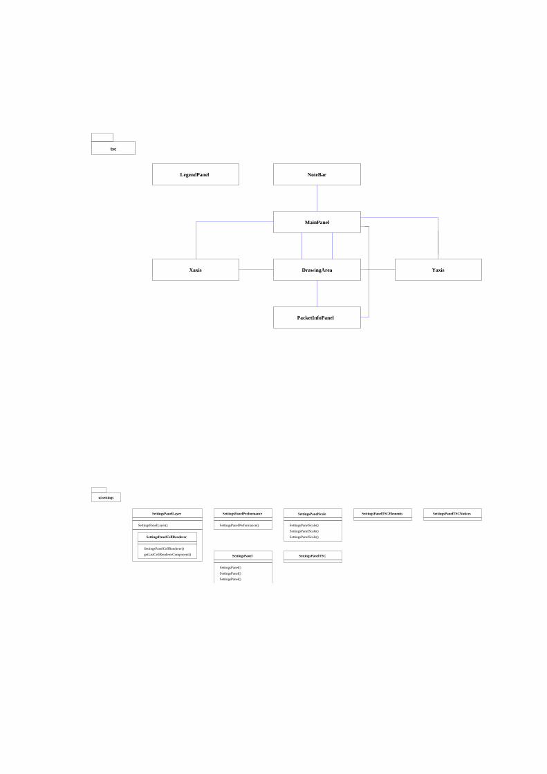
tsc
DrawingArea
MainPanel
Xaxis Yaxis
PacketInfoPanel
LegendPanel NoteBar
SettingsPanelCellRenderer()
getListCellRendererComponent()
SettingsPanelCellRenderer
SettingsPanelLayer()
SettingsPanelLayer SettingsPanelPerformance
SettingsPanelPerformance()
SettingsPanelScale
SettingsPanelScale()
SettingsPanelScale()
SettingsPanelScale()
ui.settings
SettingsPanel SettingsPanelTSC
SettingsPanelTSCElements SettingsPanelTSCNotices
SettingsPanel()
SettingsPanel()
SettingsPanel()