Embed Size (px)
Citation preview
13th World Conference on Earthquake Engineering Vancouver, B.C., Canada
August 1-6, 2004 Paper No. 2243
DEVELOPMENT AND APPLICATIONS OF TUNED/HYBRID MASS DAMPERS USING MULTI-STAGE RUBBER BEARINGS FOR VIBRATION CONTROL OF
STRUCTURES
Nobuo Masaki1, Youji Suizu2, Takayoshi Kamada3 and Takafumi Fujita4
SUMMARY The authors have been developing tuned/hybrid mass dampers using multistage rubber bearings for vibration control of structures. Multistage rubber bearings consist of small size laminated rubber bearings and stabilizing steel plates. Small size laminated rubber bearings are installed at each corner of a square shaped stabilizing plate and are stacked up with the stabilizing plate alternatively. Stabilizing plates reduce bending deformation of laminated rubber bearings under large horizontal displacement of multistage rubber bearings. Therefore multistage rubber bearings have a larger deformation capacity than that of normal shaped laminated rubber bearings with same horizontal stiffness. Tuned/hybrid mass dampers using multistage rubber bearings are applied to high-rise office buildings and hotels for control of wind-induced vibrations and earthquake excitations. And also they are installed to microwave antenna towers for seismic resistant retrofit. Small size tuned mass dampers also are applied to 3-story steel-framed houses for control of traffic-induced vibration. This paper summaries fundamental study, development and application of tuned/hybrid mass damper using multistage rubber bearing for vibration control of structures.
INTRODUCTION Tuned mass dampers have been designed to control the vibrations in tall buildings, being able to vibrate masses ranging up to 100 tons (natural period: 2~6 s, amplitude: ~ 1 m), and also being designed to be as small as possible so that the mass damper's size is the same as the height of the floor. In presented study, a mass damper with a multi-stage rubber bearing was developed having an entirely different structure than conventional types, while at the same time significantly reducing the operational friction. Using an experimental model, the vibrational characteristics were investigated using both vibration and static experiments, with results and practical use also discussed.
1 Senior Researcher, Bridgestone Corporation: [email protected] 2 Manager, Bridgestone Corporation: [email protected] 3 Associate Professor, Tokyo University of Agriculture and Technology: [email protected] 4 Professor, Institute of Industrial Science, The University of Tokyo: [email protected]
MULTI-STAGE RUBBER BEARING MASS DAMPER STRUCTURE
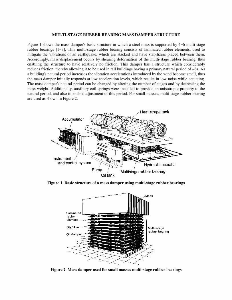
Figure 1 shows the mass damper's basic structure in which a steel mass is supported by 4~6 multi-stage rubber bearings [1~3]. This multi-stage rubber bearing consists of laminated rubber elements, used to mitigate the vibrations of an earthquake, which are stacked and have stabilizers placed between them. Accordingly, mass displacement occurs by shearing deformation of the multi-stage rubber bearing, thus enabling the structure to have relatively no friction. This damper has a structure which considerably reduces friction, thereby allowing it to be used in tall buildings having a primary natural period of ~6s. As a building's natural period increases the vibration accelerations introduced by the wind become small, thus the mass damper initially responds at low acceleration levels, which results in low noise while actuating. The mass damper's natural period can be changed by altering the number of stages and by decreasing the mass weight. Additionally, auxiliary coil springs were installed to provide an anisotropic property to the natural period, and also to enable adjustment of this period. For small masses, multi-stage rubber bearing are used as shown in Figure 2.
Figure 1 Basic structure of a mass damper using multi-stage rubber bearings
Figure 2 Mass damper used for small masses multi-stage rubber bearings
SCALE MODEL STATIC AND DYNAMIC TESTS
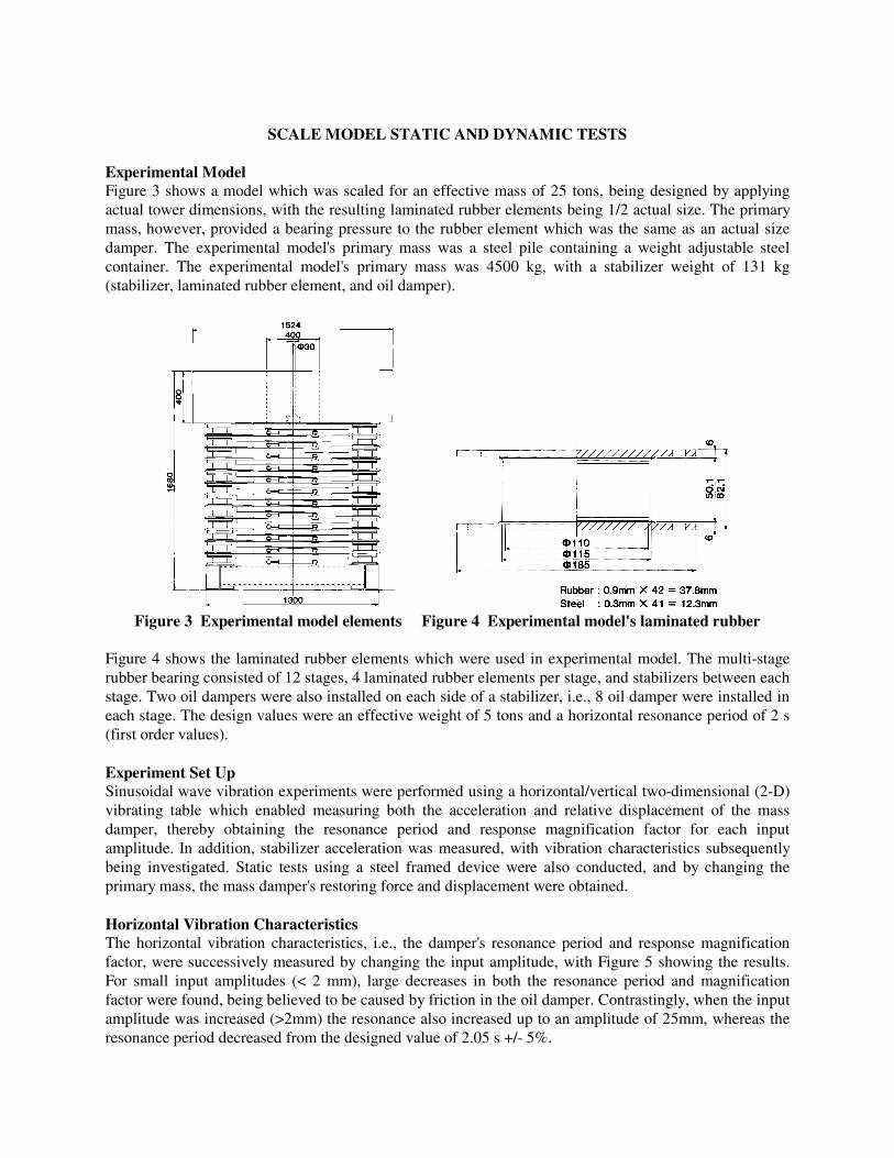
Experimental Model Figure 3 shows a model which was scaled for an effective mass of 25 tons, being designed by applying actual tower dimensions, with the resulting laminated rubber elements being 1/2 actual size. The primary mass, however, provided a bearing pressure to the rubber element which was the same as an actual size damper. The experimental model's primary mass was a steel pile containing a weight adjustable steel container. The experimental model's primary mass was 4500 kg, with a stabilizer weight of 131 kg (stabilizer, laminated rubber element, and oil damper).
Figure 3 Experimental model elements Figure 4 Experimental model's laminated rubber
Figure 4 shows the laminated rubber elements which were used in experimental model. The multi-stage rubber bearing consisted of 12 stages, 4 laminated rubber elements per stage, and stabilizers between each stage. Two oil dampers were also installed on each side of a stabilizer, i.e., 8 oil damper were installed in each stage. The design values were an effective weight of 5 tons and a horizontal resonance period of 2 s (first order values). Experiment Set Up Sinusoidal wave vibration experiments were performed using a horizontal/vertical two-dimensional (2-D) vibrating table which enabled measuring both the acceleration and relative displacement of the mass damper, thereby obtaining the resonance period and response magnification factor for each input amplitude. In addition, stabilizer acceleration was measured, with vibration characteristics subsequently being investigated. Static tests using a steel framed device were also conducted, and by changing the primary mass, the mass damper's restoring force and displacement were obtained. Horizontal Vibration Characteristics The horizontal vibration characteristics, i.e., the damper's resonance period and response magnification factor, were successively measured by changing the input amplitude, with Figure 5 showing the results. For small input amplitudes (< 2 mm), large decreases in both the resonance period and magnification factor were found, being believed to be caused by friction in the oil damper. Contrastingly, when the input amplitude was increased (>2mm) the resonance also increased up to an amplitude of 25mm, whereas the resonance period decreased from the designed value of 2.05 s +/- 5%.
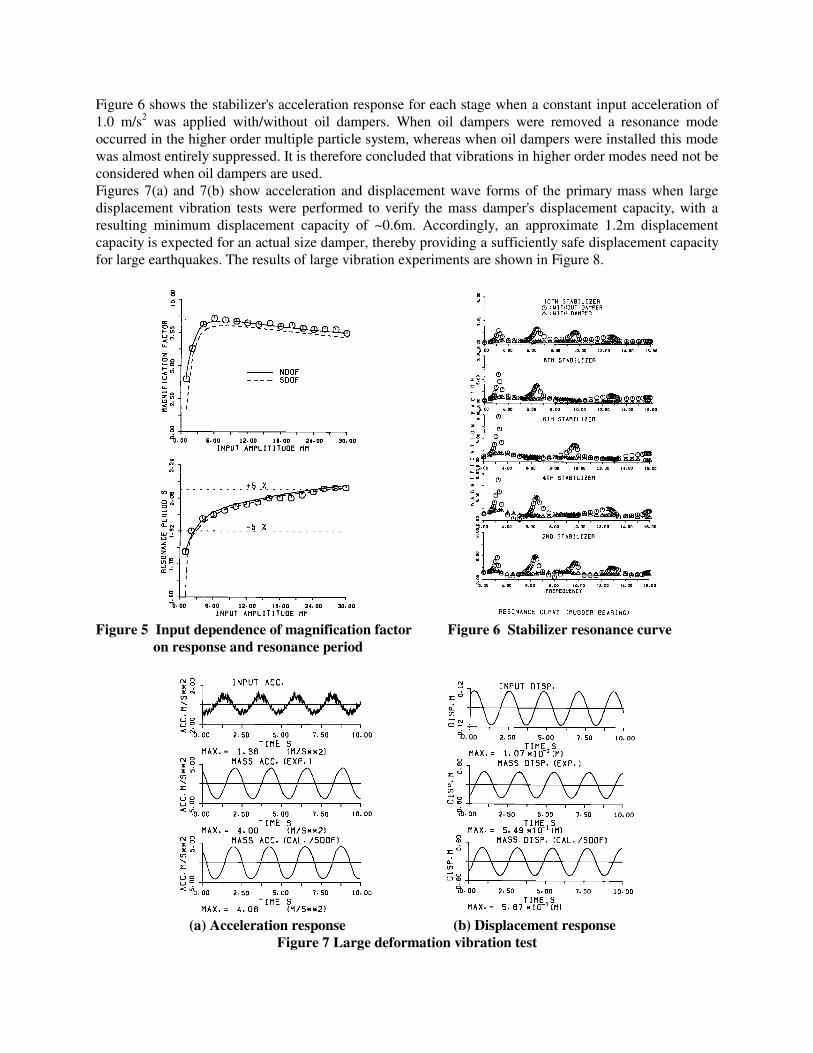
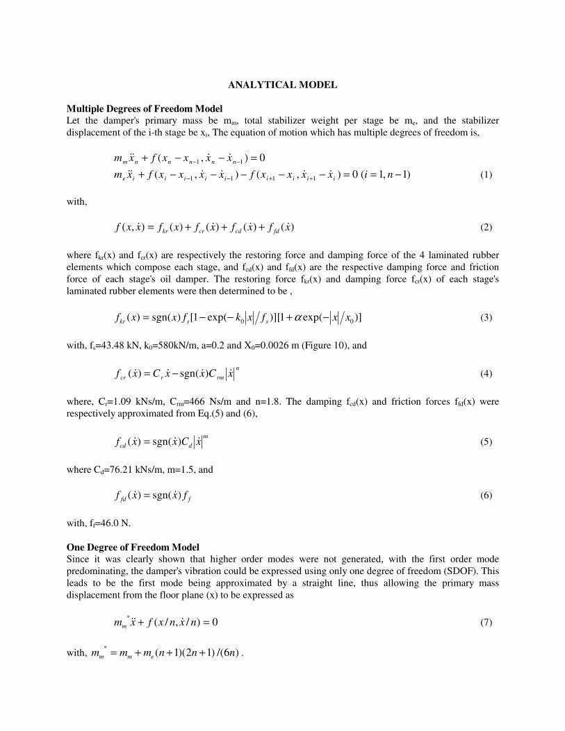
Figure 6 shows the stabilizer's acceleration response for each stage when a constant input acceleration of 1.0 m/s2 was applied with/without oil dampers. When oil dampers were removed a resonance mode occurred in the higher order multiple particle system, whereas when oil dampers were installed this mode was almost entirely suppressed. It is therefore concluded that vibrations in higher order modes need not be considered when oil dampers are used. Figures 7(a) and 7(b) show acceleration and displacement wave forms of the primary mass when large displacement vibration tests were performed to verify the mass damper's displacement capacity, with a resulting minimum displacement capacity of ~0.6m. Accordingly, an approximate 1.2m displacement capacity is expected for an actual size damper, thereby providing a sufficiently safe displacement capacity for large earthquakes. The results of large vibration experiments are shown in Figure 8.
Figure 5 Input dependence of magnification factor Figure 6 Stabilizer resonance curve on response and resonance period
(a) Acceleration response (b) Displacement response
Figure 7 Large deformation vibration test
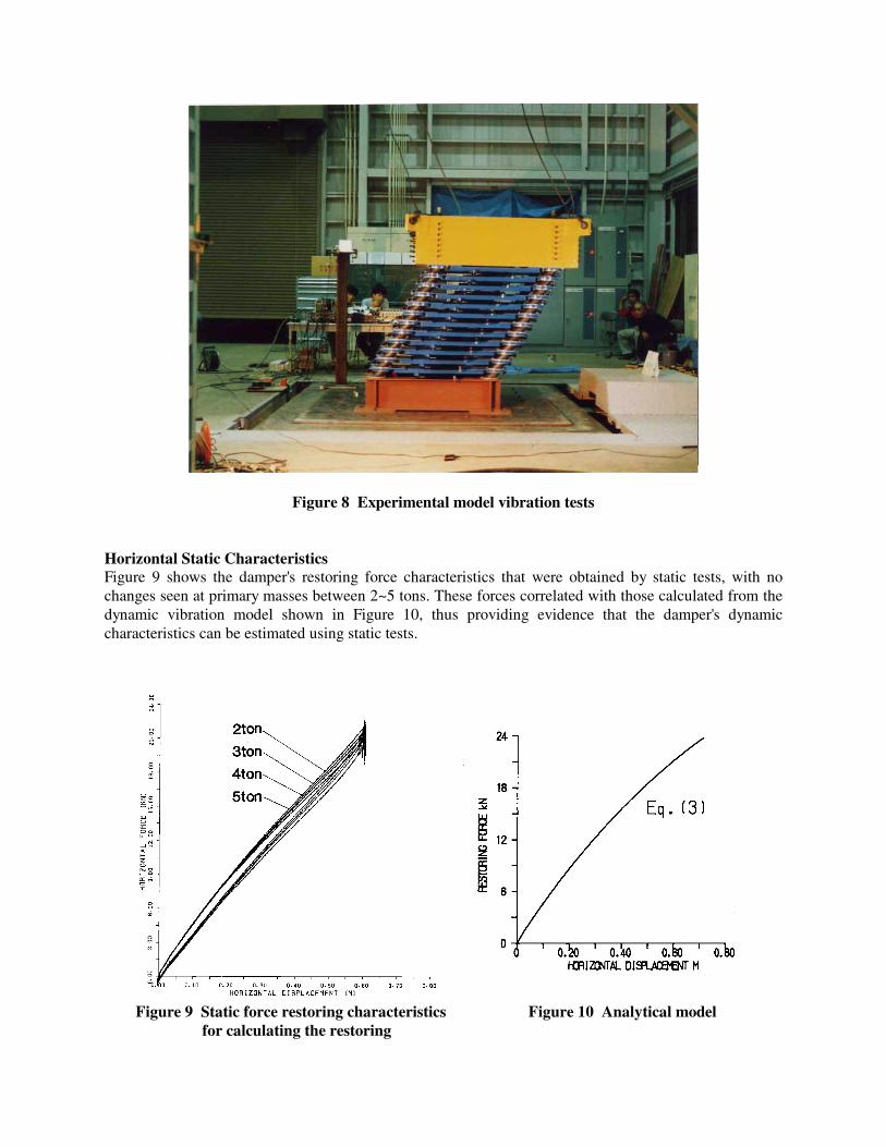
Figure 8 Experimental model vibration tests Horizontal Static Characteristics Figure 9 shows the damper's restoring force characteristics that were obtained by static tests, with no changes seen at primary masses between 2~5 tons. These forces correlated with those calculated from the dynamic vibration model shown in Figure 10, thus providing evidence that the damper's dynamic characteristics can be estimated using static tests.
Figure 9 Static force restoring characteristics Figure 10 Analytical model for calculating the restoring
ANALYTICAL MODEL
Multiple Degrees of Freedom Model Let the damper's primary mass be mm, total stabilizer weight per stage be me, and the stabilizer displacement of the i-th stage be xi, The equation of motion which has multiple degrees of freedom is, 0),( 11 =−−+ −− nnnnnm xxxxfxm &&&&
0),(),( 1111 =−−−−−+ ++−− iiiiiiiiie xxxxfxxxxfxm &&&&&& )1,1( −= ni (1)
with, )()()()(),( xfxfxfxfxxf fdcdcrkr &&&& +++= (2)
where fkr(x) and fcr(x) are respectively the restoring force and damping force of the 4 laminated rubber elements which compose each stage, and fcd(x) and ffd(x) are the respective damping force and friction force of each stage's oil damper. The restoring force fkr(x) and damping force fcr(x) of each stage's laminated rubber elements were then determined to be ,
)]exp(1)][exp(1[)sgn()( 00 xxfxkfxxf sskr −+−−= α (3)
with, fs=43.48 kN, k0=580kN/m, a=0.2 and X0=0.0026 m (Figure 10), and
n
rmrcr xCxxCxf &&&& )sgn()( −= (4)
where, Cr=1.09 kNs/m, Crm=466 Ns/m and n=1.8. The damping fcd(x) and friction forces ffd(x) were respectively approximated from Eq.(5) and (6),
m
dcd xCxxf &&& )sgn()( = (5)
where Cd=76.21 kNs/m, m=1.5, and ffd fxxf )sgn()( && = (6)
with, ff=46.0 N. One Degree of Freedom Model Since it was clearly shown that higher order modes were not generated, with the first order mode predominating, the damper's vibration could be expressed using only one degree of freedom (SDOF). This leads to be the first mode being approximated by a straight line, thus allowing the primary mass displacement from the floor plane (x) to be expressed as
0)/,/(* =+ nxnxfxmm &&& (7)
with, )6/()12)(1(* nnnmmm emm +++= .
where n is the number of stages in the multi-stage rubber bearing, and f is given by Eq (2). Equation (7) indicates that the characteristic equations of the primary mass restoring and damping forces for a SDOF system are equivalent to the multiple degree of freedom system, similar to the results shown in Figure 5, thus allowing analyses to be performed using this system.
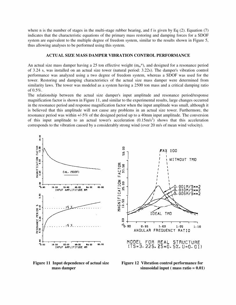
ACTUAL SIZE MASS DAMPER VIBRATION CONTROL PERFORMANCE An actual size mass damper having a 25 ton effective weight (mm*), and designed for a resonance period of 3.24 s, was installed on an actual size tower (natural period: 3.22s). The damper's vibration control performance was analyzed using a two degree of freedom system, whereas a SDOF was used for the tower. Restoring and damping characteristics of the actual size mass damper were determined from similarity laws. The tower was modeled as a system having a 2500 ton mass and a critical damping ratio of 0.5%. The relationship between the actual size damper's input amplitude and resonance period/response magnification factor is shown in Figure 11, and similar to the experimental results, large changes occurred in the resonance period and response magnification factor when the input amplitude was small, although it is believed that this amplitude will not cause any problems in an actual size tower. Furthermore, the resonance period was within +/-5% of the designed period up to a 40mm input amplitude. The conversion of this input amplitude to an actual tower's acceleration (0.15m/s2) shows that this acceleration corresponds to the vibration caused by a considerably strong wind (over 20 m/s of mean wind velocity).
Figure 11 Input dependence of actual size Figure 12 Vibration control performance for mass damper sinusoidal input ( mass ratio = 0.01)
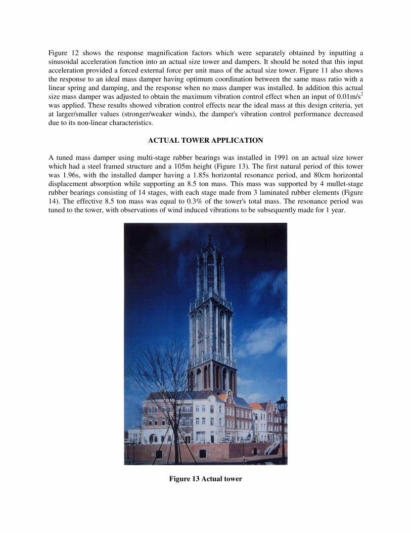
Figure 12 shows the response magnification factors which were separately obtained by inputting a sinusoidal acceleration function into an actual size tower and dampers. It should be noted that this input acceleration provided a forced external force per unit mass of the actual size tower. Figure 11 also shows the response to an ideal mass damper having optimum coordination between the same mass ratio with a linear spring and damping, and the response when no mass damper was installed. In addition this actual size mass damper was adjusted to obtain the maximum vibration control effect when an input of 0.01m/s2 was applied. These results showed vibration control effects near the ideal mass at this design criteria, yet at larger/smaller values (stronger/weaker winds), the damper's vibration control performance decreased due to its non-linear characteristics.
ACTUAL TOWER APPLICATION A tuned mass damper using multi-stage rubber bearings was installed in 1991 on an actual size tower which had a steel framed structure and a 105m height (Figure 13). The first natural period of this tower was 1.96s, with the installed damper having a 1.85s horizontal resonance period, and 80cm horizontal displacement absorption while supporting an 8.5 ton mass. This mass was supported by 4 mullet-stage rubber bearings consisting of 14 stages, with each stage made from 3 laminated rubber elements (Figure 14). The effective 8.5 ton mass was equal to 0.3% of the tower's total mass. The resonance period was tuned to the tower, with observations of wind induced vibrations to be subsequently made for 1 year.
Figure 13 Actual tower
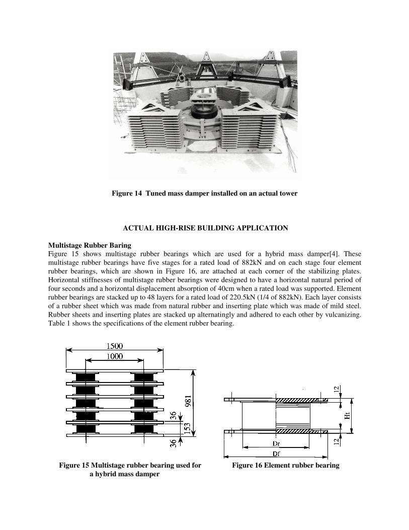
Figure 14 Tuned mass damper installed on an actual tower
ACTUAL HIGH-RISE BUILDING APPLICATION Multistage Rubber Baring Figure 15 shows multistage rubber bearings which are used for a hybrid mass damper[4]. These multistage rubber bearings have five stages for a rated load of 882kN and on each stage four element rubber bearings, which are shown in Figure 16, are attached at each corner of the stabilizing plates. Horizontal stiffnesses of multistage rubber bearings were designed to have a horizontal natural period of four seconds and a horizontal displacement absorption of 40cm when a rated load was supported. Element rubber bearings are stacked up to 48 layers for a rated load of 220.5kN (1/4 of 882kN). Each layer consists of a rubber sheet which was made from natural rubber and inserting plate which was made of mild steel. Rubber sheets and inserting plates are stacked up alternatingly and adhered to each other by vulcanizing. Table 1 shows the specifications of the element rubber bearing.
Figure 15 Multistage rubber bearing used for Figure 16 Element rubber bearing a hybrid mass damper
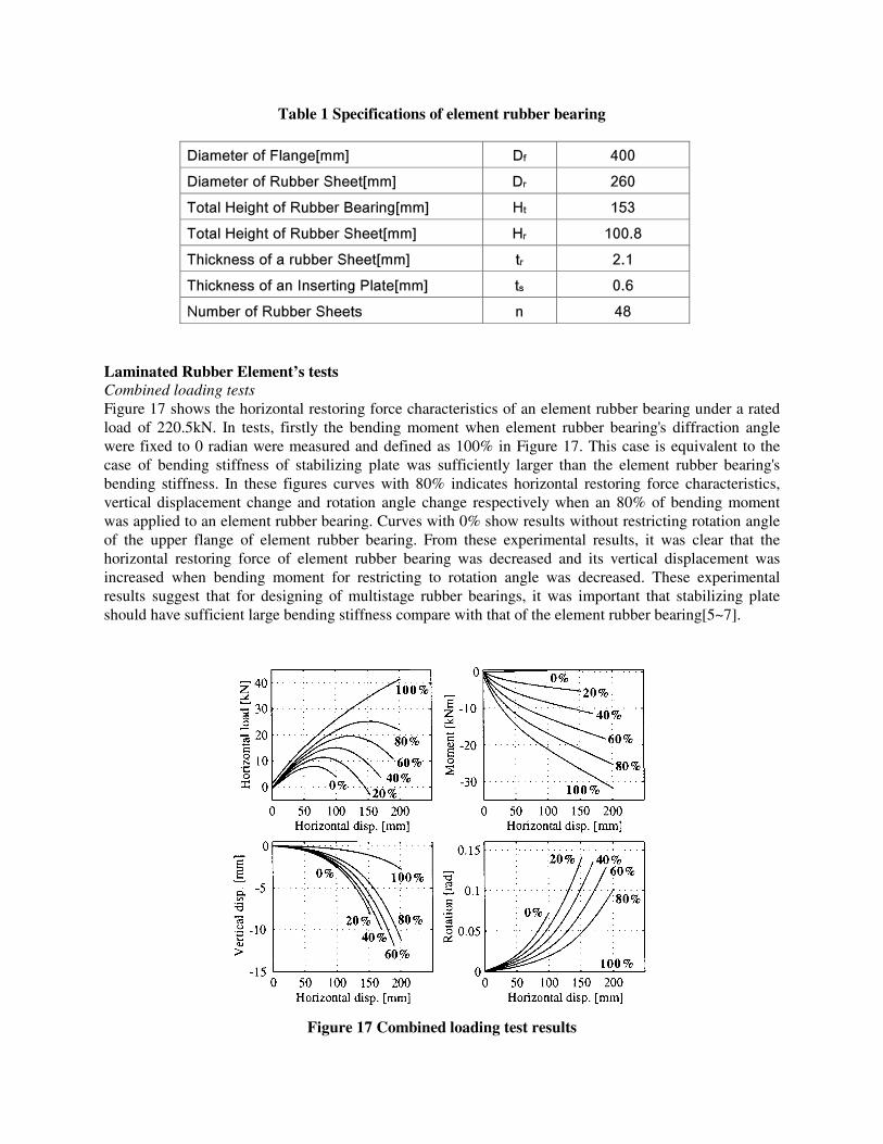
Table 1 Specifications of element rubber bearing
Diameter of Flange[mm] Df 400
Diameter of Rubber Sheet[mm] Dr 260
Total Height of Rubber Bearing[mm] Ht 153
Total Height of Rubber Sheet[mm] Hr 100.8
Thickness of a rubber Sheet[mm] tr 2.1
Thickness of an Inserting Plate[mm] ts 0.6
Number of Rubber Sheets n 48
Laminated Rubber Element’s tests Combined loading tests Figure 17 shows the horizontal restoring force characteristics of an element rubber bearing under a rated load of 220.5kN. In tests, firstly the bending moment when element rubber bearing's diffraction angle were fixed to 0 radian were measured and defined as 100% in Figure 17. This case is equivalent to the case of bending stiffness of stabilizing plate was sufficiently larger than the element rubber bearing's bending stiffness. In these figures curves with 80% indicates horizontal restoring force characteristics, vertical displacement change and rotation angle change respectively when an 80% of bending moment was applied to an element rubber bearing. Curves with 0% show results without restricting rotation angle of the upper flange of element rubber bearing. From these experimental results, it was clear that the horizontal restoring force of element rubber bearing was decreased and its vertical displacement was increased when bending moment for restricting to rotation angle was decreased. These experimental results suggest that for designing of multistage rubber bearings, it was important that stabilizing plate should have sufficient large bending stiffness compare with that of the element rubber bearing[5~7].
Figure 17 Combined loading test results
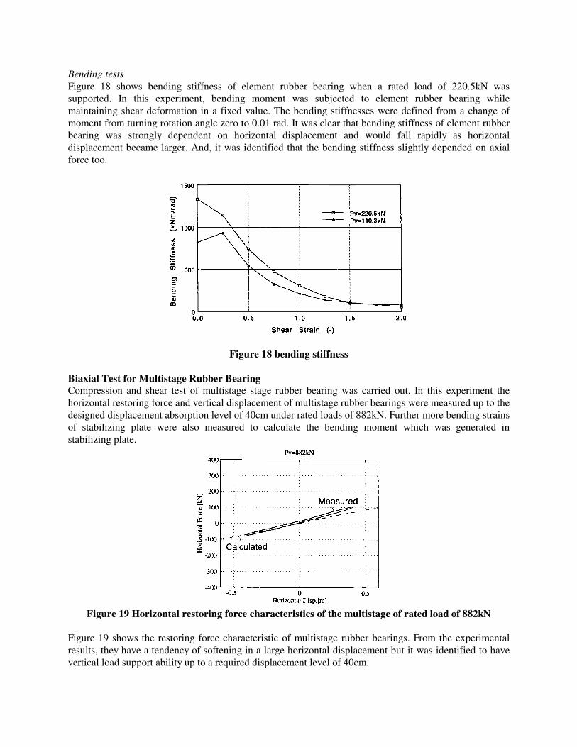
Bending tests Figure 18 shows bending stiffness of element rubber bearing when a rated load of 220.5kN was supported. In this experiment, bending moment was subjected to element rubber bearing while maintaining shear deformation in a fixed value. The bending stiffnesses were defined from a change of moment from turning rotation angle zero to 0.01 rad. It was clear that bending stiffness of element rubber bearing was strongly dependent on horizontal displacement and would fall rapidly as horizontal displacement became larger. And, it was identified that the bending stiffness slightly depended on axial force too.
Figure 18 bending stiffness Biaxial Test for Multistage Rubber Bearing Compression and shear test of multistage stage rubber bearing was carried out. In this experiment the horizontal restoring force and vertical displacement of multistage rubber bearings were measured up to the designed displacement absorption level of 40cm under rated loads of 882kN. Further more bending strains of stabilizing plate were also measured to calculate the bending moment which was generated in stabilizing plate.
Figure 19 Horizontal restoring force characteristics of the multistage of rated load of 882kN
Figure 19 shows the restoring force characteristic of multistage rubber bearings. From the experimental results, they have a tendency of softening in a large horizontal displacement but it was identified to have vertical load support ability up to a required displacement level of 40cm.
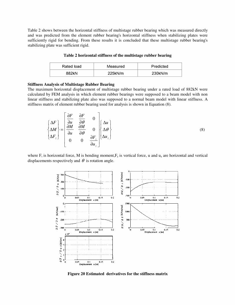
Table 2 shows between the horizontal stiffness of multistage rubber bearing which was measured directly and was predicted from the element rubber bearing's horizontal stiffness when stabilizing plates were sufficiently rigid for bending. From these results it is concluded that these multistage rubber bearing's stabilizing plate was sufficient rigid.
Table 2 horizontal stiffness of the multistage rubber bearing
Rated load Measured Predicted
882kN 225kN/m 230kN/m
Stiffness Analysis of Multistage Rubber Bearing The maximum horizontal displacement of multistage rubber bearing under a rated load of 882kN were calculated by FEM analysis in which element rubber bearings were supposed to a beam model with non linear stiffness and stabilizing plate also was supposed to a normal beam model with linear stiffness. A stiffness matrix of element rubber bearing used for analysis is shown in Equation (8).
∆∆∆
∂∂
∂∂
∂∂
∂∂
∂∂
=
∆∆∆
z
z
zz u
u
u
F
M
u
M
F
u
F
F
M
F
θθ
θ
00
0
0
(8)
where F, is horizontal force, M is bending moment,Fz is vertical force, u and uz are horizontal and vertical displacements respectively and θ is rotation angle.
Figure 20 Estimated derivatives for the stiffness matrix
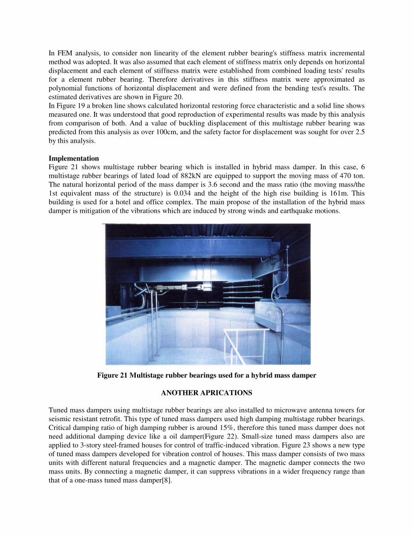
In FEM analysis, to consider non linearity of the element rubber bearing's stiffness matrix incremental method was adopted. It was also assumed that each element of stiffness matrix only depends on horizontal displacement and each element of stiffness matrix were established from combined loading tests' results for a element rubber bearing. Therefore derivatives in this stiffness matrix were approximated as polynomial functions of horizontal displacement and were defined from the bending test's results. The estimated derivatives are shown in Figure 20. In Figure 19 a broken line shows calculated horizontal restoring force characteristic and a solid line shows measured one. It was understood that good reproduction of experimental results was made by this analysis from comparison of both. And a value of buckling displacement of this multistage rubber bearing was predicted from this analysis as over 100cm, and the safety factor for displacement was sought for over 2.5 by this analysis. Implementation Figure 21 shows multistage rubber bearing which is installed in hybrid mass damper. In this case, 6 multistage rubber bearings of lated load of 882kN are equipped to support the moving mass of 470 ton. The natural horizontal period of the mass damper is 3.6 second and the mass ratio (the moving mass/the 1st equivalent mass of the structure) is 0.034 and the height of the high rise building is 161m. This building is used for a hotel and office complex. The main propose of the installation of the hybrid mass damper is mitigation of the vibrations which are induced by strong winds and earthquake motions.
Figure 21 Multistage rubber bearings used for a hybrid mass damper
ANOTHER APRICATIONS
Tuned mass dampers using multistage rubber bearings are also installed to microwave antenna towers for seismic resistant retrofit. This type of tuned mass dampers used high damping multistage rubber bearings. Critical damping ratio of high damping rubber is around 15%, therefore this tuned mass damper does not need additional damping device like a oil damper(Figure 22). Small-size tuned mass dampers also are applied to 3-story steel-framed houses for control of traffic-induced vibration. Figure 23 shows a new type of tuned mass dampers developed for vibration control of houses. This mass damper consists of two mass units with different natural frequencies and a magnetic damper. The magnetic damper connects the two mass units. By connecting a magnetic damper, it can suppress vibrations in a wider frequency range than that of a one-mass tuned mass damper[8].
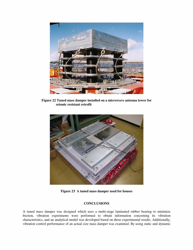
Figure 22 Tuned mass damper installed on a microwave antenna tower for seismic resistant retrofit
Figure 23 A tuned mass damper used for houses
CONCLUSIONS A tuned mass damper was designed which uses a multi-stage laminated rubber bearing to minimize friction, vibration experiments were performed to obtain information concerning its vibration characteristics, and an analytical model was developed based on these experimental results. Additionally, vibration control performance of an actual size mass damper was examined. By using static and dynamic

tests, it was confirmed that this mass damper could be put to practical use. The development of a tuned mass damper for high rise buildings that is actively controlled by using oil hydraulic actuators and multi-stage rubber bearings was also completed and it had been in practice. Large scale multistage rubber bearings which can be used for a hybrid mass damper are developed. By biaxial loading tests for multistage rubber bearing and combined loading tests (shear, compression and bending) for element rubber bearings, it was confirmed these multistage rubber bearings had performances which are required in vibration control of structure during seismic and strong wind excitations. It was also confirmed a method by which element rubber bearing's stiffness matrix could be determined by combined loading tests experimentally for FEM analysis. In this method stiffness matrices were defined in which each element had non linear elastic stiffnesses. Calculated restoring force characteristics were agreed with experimental results. Further more by using FEM's large deformation analysis with these stiffness matrices, the buckling displacement of these multistage rubber bearings could be predicted. And safety factor for displacement absorption under a rated axial load were determined.
ACKNOWLEDGMENTS The authors would like to express their appreciation to Nihon Sekkei, INC., Shimizu Corporation and Takenaka Corporation for the reproduce of the photograph of the actual tower.
REFERENCES 1. Fujita T, Mori F, Masaki N and Suizu Y, “Experimental Study of Multi-stage Rubber Bearings
Developed for an Isolation Floor for Earthquakes and Ambient Micro-Vibration”, Trans. of JSME, Vol.53, No.485, Ser.C, 71-76, 1987.(in Japanese)
2. Fujita T, Matsumoto Y, Masaki N, Suizu Y, “Tuned Mass Damper Using Multistage Rubber Baring for Vibration Control of Tall Buildings (1st Report, Fundamental Study of the Vibration Characteristics)”, Trans. of JSME, Vol.56, No.523, Ser.C, 634-639, 1990.(in Japanese)
3. Fujita T, Masaki N and Suizu Y, “Tuned Mass Damper using a Multi-stage Rubber Bearing for Vibration Control of Tall Buildings”, Proceedings of the 1991 Asia-Pacific vibration conference, 9.13-18, 1991.
4. Masaki N and Suizu Y, “Development of Multistage Rubber Bearing for Seismic Isolation of Buildings”, Proceedings of IRC95 KOBE, 225-228, 1995.
5. Masaki N, “Restoring Force Characteristics of Laminated Rubber Bearings used for Base Isolation and Vibration Control Devices (Effect of Rotation on Static Restoring Force Characteristics of Rubber Bearings)”, Trans. of JSME, Vol.64, No.624, Ser.C, 2915-2922, 1998.(in Japanese)
6. Masaki N and Tamura K, “stiffness Analysis of Large Scale Multistage Rubber Bearing used for Mass Dampers”, Trans. of JSME, Vol.65, No.631, Ser.C, 902-909, 1999.(in Japanese)
7. Masaki N and Suzuki S, “Restoring Force Characteristics of Laminated Rubber Bearings under various restraining Conditions”, Transactions of the ASME, Journal of Pressure Vessel Technology, Volume 126, Number 1, 141-147, February, 2004.
8. Masaki N and Hirata H, “Vibration Control Performance of Damping Coupled Tuned Mass Dampers”, ASME PVP2004 Conference, 2004.(in press)