Embed Size (px)
Citation preview
Proceedings World Geothermal Congress 2015
Melbourne, Australia, 19-25 April 2015
1
Development of Thermal Response Test Device with Automatic Control System
Hiroyuki Kosukegawa and Hikari Fujii
Akita University, 1-1 Gakuen-cho, Tegata, Akita, 010-8502, Japan
E-mail: [email protected]
Keywords: ground source heat pumps, thermal response test, borehole heat exchanger
ABSTRACT
In ground source heat pump (GSHP) systems, it is important to carry out thermal response tests (TRTs) to estimate the thermal
conductivity of the ground with good accuracy for the optimum design of the system. In conventional TRTs, the circulating
medium is heated by heaters of rated output, and the flow rate of the medium is controlled by flow valves. It is important to
maintain a constant heat load in TRTs, but the constant heat load is difficult to achieve, if there is a major change in the ambient
temperature, in the flow rate or in the supply voltage to the heater. Hence, in this study we developed TRT equipment that
automatically controls the heat load on ground heat exchangers to improve the accuracy of TRTs. In the device, we use the PLC
(Programmed Logic Controller) for monitoring the heat load and for controlling the system, and adjust the thermal output of the
heater to designated values. We carried out two types of TRTs, one with controlled output on the heater with PLC and the other
fixed output without controlling, in an experimental borehole of 100 m deep in the campus of Akita University. In the operation
tests, we gave the TRT device two types of disturbances, i.e., 1) change in the flow rate of heat medium, 2) reduction of the supply
voltage to the heater. Firstly, we examined the effect of the disturbance and found that the influence was insignificant in the first
case. On the other hand, the disturbance was clearly observed when the supply voltage was decreased. Then, we examined the
performance of the developed TRT equipment by comparing the change of heat load with or without the use of PLC by giving a
disturbance on the supply voltage. As a result, when the PLC was not in use, heat load reduced as heater supply voltage was
decreased. When the PLC is in use, the reduction of heat load was small and the heat load recovered to the designated values in
about 150 seconds from the decrease of the heater supply voltage. Then we carried out TRTs while giving a variation of the heater
supply voltage as a disturbance. The TRTs showed that when disturbances were given on supply voltage, the PLC gave a good
linearity on the average temperature of heat medium. The estimated thermal conductivity was close enough to the one measured
without disturbances. Furthermore, the comparison of estimated thermal conductivity values between the TRTs (with disturbance)
with or without PLC control gave differences of 10-30%. This indicates that the developed device improves the accuracy in the
estimation of soil thermal properties, which will contribute to the optimum design of GSHP systems.
1. INTRODUCTION
When designing a ground source heat pump (GSHP) system, Thermal Response Tests (TRTs) are carried out in vertical borehole
heat exchangers (BHEs). Since TRTs are usually performed in the outdoors, portable TRT units are developed in many countries
(Sanner et al., 2005). In TRTs, constant heat load is given on BHEs for 2-3 days to determine the slope of temperature transient
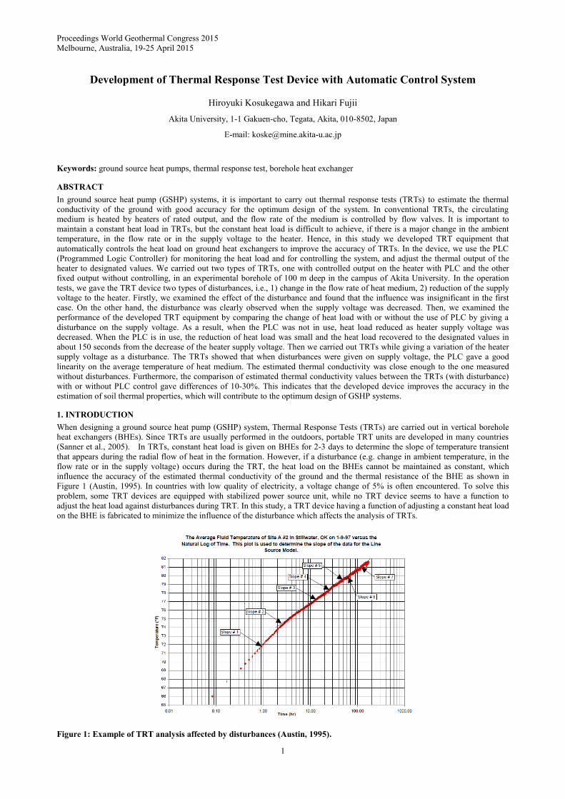
that appears during the radial flow of heat in the formation. However, if a disturbance (e.g. change in ambient temperature, in the
flow rate or in the supply voltage) occurs during the TRT, the heat load on the BHEs cannot be maintained as constant, which
influence the accuracy of the estimated thermal conductivity of the ground and the thermal resistance of the BHE as shown in
Figure 1 (Austin, 1995). In countries with low quality of electricity, a voltage change of 5% is often encountered. To solve this
problem, some TRT devices are equipped with stabilized power source unit, while no TRT device seems to have a function to
adjust the heat load against disturbances during TRT. In this study, a TRT device having a function of adjusting a constant heat load
on the BHE is fabricated to minimize the influence of the disturbance which affects the analysis of TRTs.
Figure 1: Example of TRT analysis affected by disturbances (Austin, 1995).

Kosukegawa et al.
2
2. TRT DEVICE
In this study, we developed a TRT device with automatic heat output control is shown in Figure 2. The main components of the
device are shown in Table 1. The test procedure and the specification of TRT equipment are based on the guidelines which have
been discussed and presented in the IEA/ECES ANNEX21 report (IEA ECES ANNEX21, 2013). The heat medium is heated using
an electric heater and the heat medium is circulated by the circulation pump through the U-tube to inject heat into the formation.
The obtained data are analyzed to evaluate the thermal conductivity and thermal resistance. The piping in the TRT device is
thermally insulated to reduce the influence of the atmosphere temperature. For the control of the thermal output of the TRT device,
we apply the PLC (Programmed Logic Controller) to maintain the designated values of heat load automatically. PLC is a digital
computer used for automation of electromechanical process, such as control of machinery on factory assembly lines, elevators or
automatic doors. PLC used in this device is composed of a main (CPU) unit, PID unit and A/D unit.
Figure 2: Thermal response test device.
Table 1: Main components of the TRT device.
Circulation pump UPS 25-70 180 (GRUNDFOS)
Heater PSH-2306 (IZUMI DENNETSU CO., LTD)
Flow meter FD-M50AY (KEYENCE)
Temperature sensors FTNA1HE3-A11Y (FUJI ELECTRONICS) 1YRP731 (CHINO)
PLC Units

Kosukegawa et al.
3
KV-700, KV-TF40, KV-AD40 (KEYENCE)
Solid State Relay G3PE-545B-3N (OMRON)
Data Logger GR-3500 (KEYENCE)
3. ABOUT OF AUTOMATIC CONTROL SYSTEM
Figure 3 and Figure 4 are the schematic drawing of TRT device and a flow chart of output control, respectively. In this device, the
heat load is calculated with PLC to maintain the designated values of heat load, and the output of the heater is adjusted
automatically by the PID control. As an additional safety feature, the TRT device automatically stops the operation when the
circulation rate becomes less than 8L/min.
Figure 3: Schematic drawing of TRT device.
Figure 4: Flow chart.
4. EXPERIMENT
4.1 Test well
We conducted field tests in a test well drilled in the Tegata Campus of Akita University, Akita City, Japan (Figure 5). Figure 6
shows the completion of the test well. A thermal tracer test was carried out by injecting hot water into the BHE while measuring the

Kosukegawa et al.
4
temperature profiles in the BHE. The test showed that the upper Quaternary formation between the surface and 60m deep has high
hydraulic conductivity, while the Tertiary formation below 60 m has low hydraulic conductivity. The depth of the U-tube was set as
60 m, the bottom of the Quaternary formation, during the field tests.
Figure 5: Location of Akita University.
Figure 6: Completion sketch of test well.
4.2 Preliminary field tests
We carried out a preliminary field tests using the TRT device to examine the effect of disturbance on the measurement and the
response of the heat load against disturbance. The experimental conditions and results are shown below: a) change of the flow rate:
Base case is set as 15L/min, and to increase or decresase every 1L/min, b) change of the supply voltage to the heater; decrease of
the voltage by a thylister regulator. Figure 7 shows the measured temperatures of heat medium when flow rate was changed and
Figure 8 shows the same graph when supply voltage was changed. In Figure 7, the residence time of the fluid in the BHE was
changed with the change in the circulation rate. As a result, the temperature of the heat medium changed for a short time but the
changes in the average temperature of the heat medium is judged as too small to affect the interpretation of TRTs. On the other
hand, the inlet temperature decreased significantly with the drop of the voltage and the heat load was also significantly reduced.
From these results, the heater supply voltage was judges to be more influential on the interpretation accuracy of TRT.
N40°
Akita

Kosukegawa et al.
5
Figure 7: Measured temperature with the change of flow rate of heat medium.
Figure 8: Measured temperature with the change of heater supply voltage without control.
Figure 9 shows the measured temperatures of heat medium with the reduction of supply voltage to the heater when PLC was
applied. The inlet temperature and heat load were temporarily reduced upon change of the supply voltage, but recovered to the
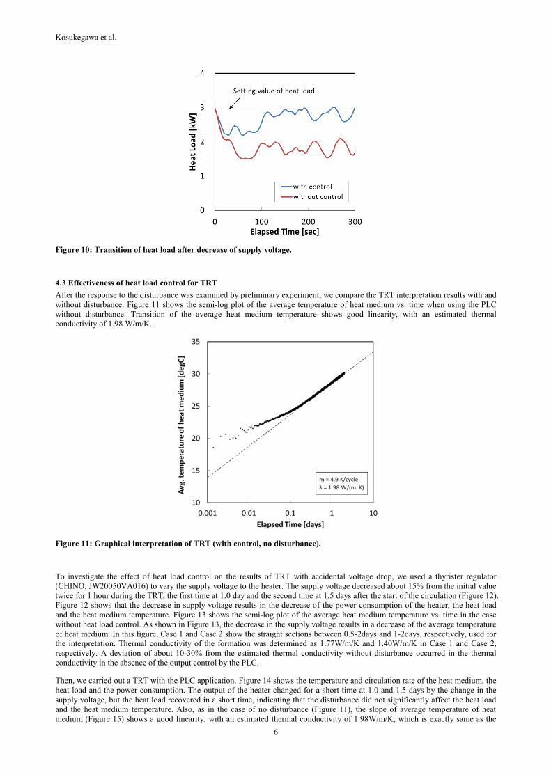
designated levels in 150 seconds. Figure 10 compares the behavior of heat load during the reduction of supply voltage with or
without the use of the PLC. This figure shows that the stability of the heat load was significantly improved with the application of
the PLC and also the initial reduction of heat load was reduced by about 50% with the use of PLC.
Figure 9: Measurement data with the change of heater supply voltage with control.
Kosukegawa et al.
6
Figure 10: Transition of heat load after decrease of supply voltage.
4.3 Effectiveness of heat load control for TRT
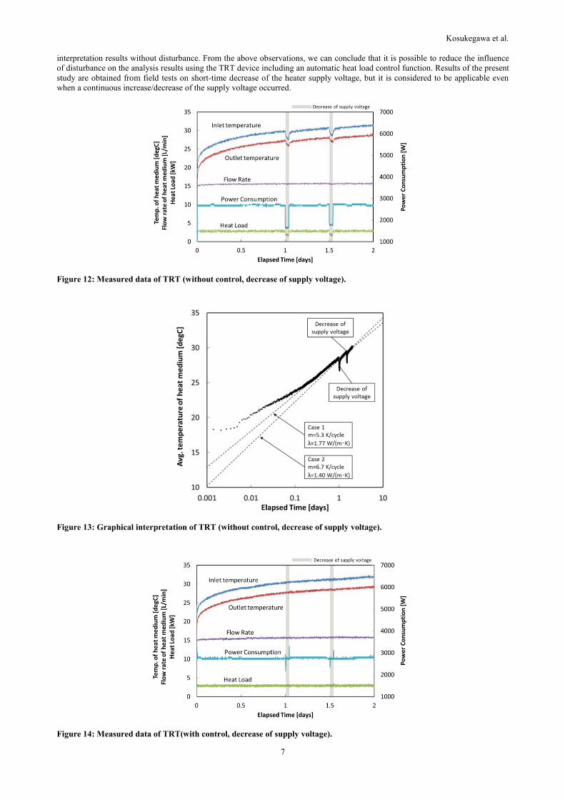
After the response to the disturbance was examined by preliminary experiment, we compare the TRT interpretation results with and
without disturbance. Figure 11 shows the semi-log plot of the average temperature of heat medium vs. time when using the PLC
without disturbance. Transition of the average heat medium temperature shows good linearity, with an estimated thermal
conductivity of 1.98 W/m/K.
Figure 11: Graphical interpretation of TRT (with control, no disturbance).
To investigate the effect of heat load control on the results of TRT with accidental voltage drop, we used a thyrister regulator
(CHINO, JW20050VA016) to vary the supply voltage to the heater. The supply voltage decreased about 15% from the initial value
twice for 1 hour during the TRT, the first time at 1.0 day and the second time at 1.5 days after the start of the circulation (Figure 12).
Figure 12 shows that the decrease in supply voltage results in the decrease of the power consumption of the heater, the heat load
and the heat medium temperature. Figure 13 shows the semi-log plot of the average heat medium temperature vs. time in the case
without heat load control. As shown in Figure 13, the decrease in the supply voltage results in a decrease of the average temperature
of heat medium. In this figure, Case 1 and Case 2 show the straight sections between 0.5-2days and 1-2days, respectively, used for
the interpretation. Thermal conductivity of the formation was determined as 1.77W/m/K and 1.40W/m/K in Case 1 and Case 2,
respectively. A deviation of about 10-30% from the estimated thermal conductivity without disturbance occurred in the thermal
conductivity in the absence of the output control by the PLC.
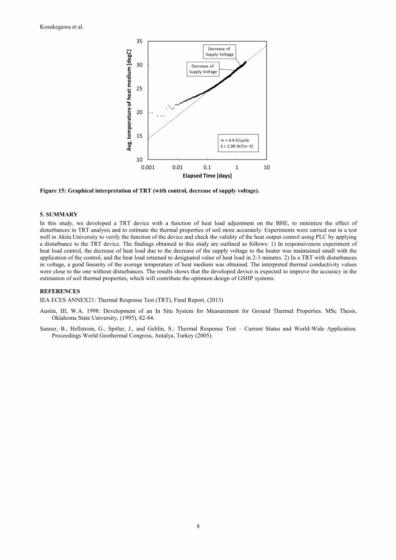
Then, we carried out a TRT with the PLC application. Figure 14 shows the temperature and circulation rate of the heat medium, the
heat load and the power consumption. The output of the heater changed for a short time at 1.0 and 1.5 days by the change in the
supply voltage, but the heat load recovered in a short time, indicating that the disturbance did not significantly affect the heat load
and the heat medium temperature. Also, as in the case of no disturbance (Figure 11), the slope of average temperature of heat
medium (Figure 15) shows a good linearity, with an estimated thermal conductivity of 1.98W/m/K, which is exactly same as the
Kosukegawa et al.
7
interpretation results without disturbance. From the above observations, we can conclude that it is possible to reduce the influence
of disturbance on the analysis results using the TRT device including an automatic heat load control function. Results of the present
study are obtained from field tests on short-time decrease of the heater supply voltage, but it is considered to be applicable even
when a continuous increase/decrease of the supply voltage occurred.
Figure 12: Measured data of TRT (without control, decrease of supply voltage).
Figure 13: Graphical interpretation of TRT (without control, decrease of supply voltage).
Figure 14: Measured data of TRT(with control, decrease of supply voltage).
Kosukegawa et al.
8
Figure 15: Graphical interpretation of TRT (with control, decrease of supply voltage).
5. SUMMARY
In this study, we developed a TRT device with a function of heat load adjustment on the BHE, to minimize the effect of
disturbances in TRT analysis and to estimate the thermal properties of soil more accurately. Experiments were carried out in a test
well in Akita University to verify the function of the device and check the validity of the heat output control using PLC by applying
a disturbance to the TRT device. The findings obtained in this study are outlined as follows: 1) In responsiveness experiment of
heat load control, the decrease of heat load due to the decrease of the supply voltage to the heater was maintained small with the
application of the control, and the heat load returned to designated value of heat load in 2-3 minutes. 2) In a TRT with disturbances
in voltage, a good linearity of the average temperature of heat medium was obtained. The interpreted thermal conductivity values
were close to the one without disturbances. The results shows that the developed device is expected to improve the accuracy in the
estimation of soil thermal properties, which will contribute the optimum design of GSHP systems.
REFERENCES
IEA ECES ANNEX21: Thermal Response Test (TRT), Final Report, (2013)
Austin, III, W.A. 1998: Development of an In Situ System for Measurement for Ground Thermal Properties. MSc Thesis,
Oklahoma State University, (1995), 82-84.
Sanner, B., Hellstrom, G., Spitler, J., and Gehlin, S.: Thermal Response Test – Current Status and World-Wide Application.
Proceedings World Geothermal Congress, Antalya, Turkey (2005).