Embed Size (px)
Citation preview

Digital Design — Chapter 8 — I/O Interfacing 8 November 2007
1
Digital Design:An Embedded Systems Approach Using VHDL
Chapter 8I/O Interfacing
Portions of this work are from the book, Digital Design: An Embedded Systems Approach Using VHDL, by Peter J. Ashenden, published by Morgan Kaufmann Publishers, Copyright 2007 Elsevier Inc. All rights reserved.
Digital Design — Chapter 8 — I/O Interfacing 2
VHDL
I/O Devices and Transducers
Transducers convert between real-world effects and digital representation
Input transducers: sensorsMay require analog-to-digital converter (ADC)
Output transducers: actuatorsMay require digital-to-analog converter (DAC)
Human-interface devicesButtons, switches, knobs, keypads, mouseIndicators, displays, speakers
Digital Design — Chapter 8 — I/O Interfacing 8 November 2007
2
Digital Design — Chapter 8 — I/O Interfacing 3
VHDL
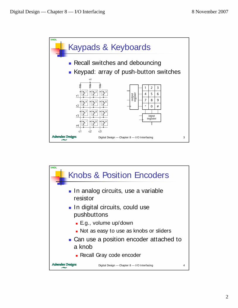
Kaypads & Keyboards
Recall switches and debouncingKeypad: array of push-button switches
321
654
987
#0*
c1 c2 c3
r1
r2
r3
r4
+V
1 2 3
4 5 6
7 8 9
* 0 #
inputregister
outp
utre
gist
er
Digital Design — Chapter 8 — I/O Interfacing 4
VHDL
Knobs & Position Encoders
In analog circuits, use a variable resistorIn digital circuits, could use pushbuttons
E.g., volume up/downNot as easy to use as knobs or sliders
Can use a position encoder attached to a knob
Recall Gray code encoder

Digital Design — Chapter 8 — I/O Interfacing 8 November 2007
3
Digital Design — Chapter 8 — I/O Interfacing 5
VHDL
Incremental Encoder
If absolute position is not important, incremental encoder is simpler
A
B
A B
A
B
counterclockwise
clockwise
Digital Design — Chapter 8 — I/O Interfacing 6
VHDL
Analog Inputs
Physical effect produces an analog voltage or currentMicrophone
In phones, cameras, voice recorders, …
AccelerometerIn airbag controllers
Fluid-flow sensorsIn industrial machines, coffee machines, …
Gas detectorsIn safety equipment
Digital Design — Chapter 8 — I/O Interfacing 8 November 2007
4
Digital Design — Chapter 8 — I/O Interfacing 7
VHDL
Analog-to-Digital Converters
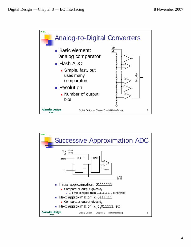
Basic element: analog comparatorFlash ADC
Simple, fast, but uses many comparators
ResolutionNumber of output bits
+–
+–
+–
+–
+–
VinVf
Enco
der
Digital Design — Chapter 8 — I/O Interfacing 8
VHDL
Successive Approximation ADC
Initial approximation: 01111111Comparator output gives d7
1 if Vin is higher than 01111111, 0 otherwise
Next approximation: d70111111Comparator output gives d6
Next approximation: d7d6011111, etc
+–
DACSAR
Doutdone
VinVf
start
clk
(analog)
(analog)
(analog)
Digital Design — Chapter 8 — I/O Interfacing 8 November 2007
5
Digital Design — Chapter 8 — I/O Interfacing 9
VHDL
LED Indicators
Single LED shows 1-bit stateOn/off, busy/ready, error/ok, …
outputdriver
+V Brightness depends on current
Determined by resistorI = (+V – VLED – VOL) / R
Digital Design — Chapter 8 — I/O Interfacing 10
VHDL
7-Segment LED Displays
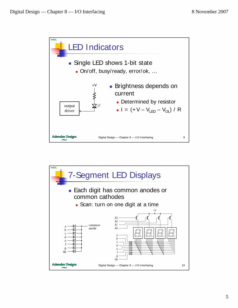
Each digit has common anodes or common cathodes
Scan: turn on one digit at a time
abcdefg
dp
commonanode
A3
A2
A1
A0
a
b
c
d
e
f
g
dp
+V
Digital Design — Chapter 8 — I/O Interfacing 8 November 2007
6
Digital Design — Chapter 8 — I/O Interfacing 11
VHDL
Example: Multiplexed Display
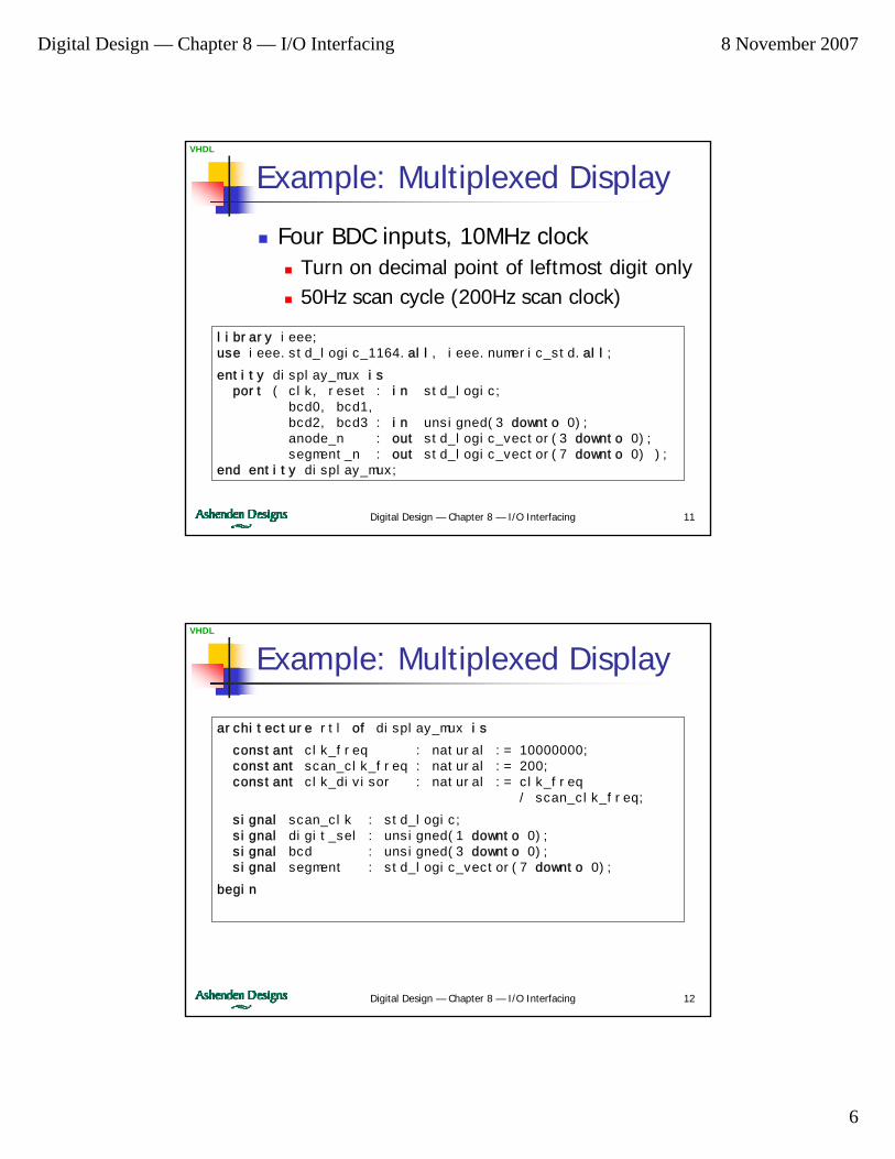
Four BDC inputs, 10MHz clockTurn on decimal point of leftmost digit only50Hz scan cycle (200Hz scan clock)
library ieee;use ieee.std_logic_1164.all, ieee.numeric_std.all;
entity display_mux isport ( clk, reset : in std_logic;
bcd0, bcd1,bcd2, bcd3 : in unsigned(3 downto 0);anode_n : out std_logic_vector(3 downto 0);segment_n : out std_logic_vector(7 downto 0) );
end entity display_mux;
Digital Design — Chapter 8 — I/O Interfacing 12
VHDL
Example: Multiplexed Display
architecture rtl of display_mux is
constant clk_freq : natural := 10000000;constant scan_clk_freq : natural := 200;constant clk_divisor : natural := clk_freq
/ scan_clk_freq;
signal scan_clk : std_logic;signal digit_sel : unsigned(1 downto 0);signal bcd : unsigned(3 downto 0);signal segment : std_logic_vector(7 downto 0);
begin
Digital Design — Chapter 8 — I/O Interfacing 8 November 2007
7
Digital Design — Chapter 8 — I/O Interfacing 13
VHDL
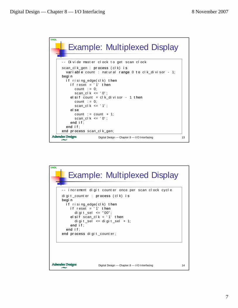
Example: Multiplexed Display-- Divide master clock to get scan clock
scan_clk_gen : process (clk) isvariable count : natural range 0 to clk_divisor - 1;
beginif rising_edge(clk) then
if reset = '1' thencount := 0;scan_clk <= '0';
elsif count = clk_divisor - 1 thencount := 0;scan_clk <= '1';
elsecount := count + 1;scan_clk <= '0';
end if;end if;
end process scan_clk_gen;
Digital Design — Chapter 8 — I/O Interfacing 14
VHDL
Example: Multiplexed Display-- increment digit counter once per scan clock cycle
digit_counter : process (clk) isbegin
if rising_edge(clk) thenif reset = '1' then
digit_sel <= "00";elsif scan_clk = '1' then
digit_sel <= digit_sel + 1;end if;
end if;end process digit_counter;
Digital Design — Chapter 8 — I/O Interfacing 8 November 2007
8
Digital Design — Chapter 8 — I/O Interfacing 15
VHDL
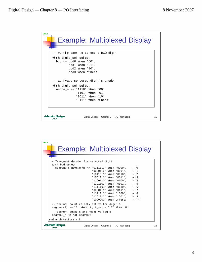
Example: Multiplexed Display-- multiplexer to select a BCD digit
with digit_sel selectbcd <= bcd0 when "00",
bcd1 when "01",bcd2 when "10",bcd3 when others;
-- activate selected digit's anode
with digit_sel selectanode_n <= "1110" when "00",
"1101" when "01","1011" when "10","0111" when others;
Digital Design — Chapter 8 — I/O Interfacing 16
VHDL
Example: Multiplexed Display-- 7-segment decoder for selected digitwith bcd selectsegment(6 downto 0) <= "0111111" when "0000", -- 0
"0000110" when "0001", -- 1"1011011" when "0010", -- 2"1001111" when "0011", -- 3"1100110" when "0100", -- 4"1101101" when "0101", -- 5"1111101" when "0110", -- 6"0000111" when "0111", -- 7"1111111" when "1000", -- 8"1101111" when "1001", -- 9"1000000" when others; -- "-"
-- decimal point is only active for digit 3segment(7) <= '1' when digit_sel = "11" else '0';
-- segment outputs are negative logicsegment_n <= not segment;
end architecture rtl;
Digital Design — Chapter 8 — I/O Interfacing 8 November 2007
9
Digital Design — Chapter 8 — I/O Interfacing 17
VHDL
Liquid Crystal Displays (LCDs)
AdvantagesLow powerReadable in bright ambient light conditionsCustom segment shapes
DisadvantagesRequire backlight for dark conditionsNot as robust as LEDs
LCD panelsRectangular array of pixelsCan be used for alphanumeric/graphical displayControlled by a small microcontroller
Digital Design — Chapter 8 — I/O Interfacing 18
VHDL
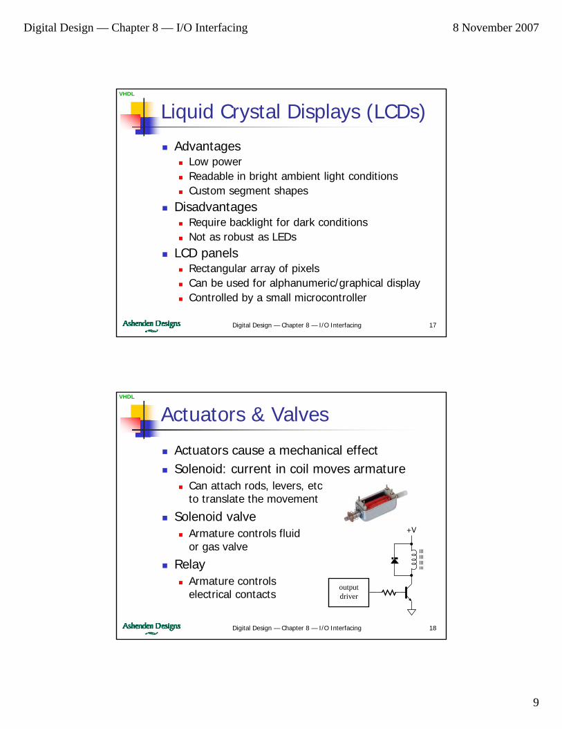
Actuators & Valves
Actuators cause a mechanical effectSolenoid: current in coil moves armature
Can attach rods, levers, etcto translate the movement
Solenoid valveArmature controls fluidor gas valve
RelayArmature controlselectrical contacts
outputdriver
+V
Digital Design — Chapter 8 — I/O Interfacing 8 November 2007
10
Digital Design — Chapter 8 — I/O Interfacing 19
VHDL
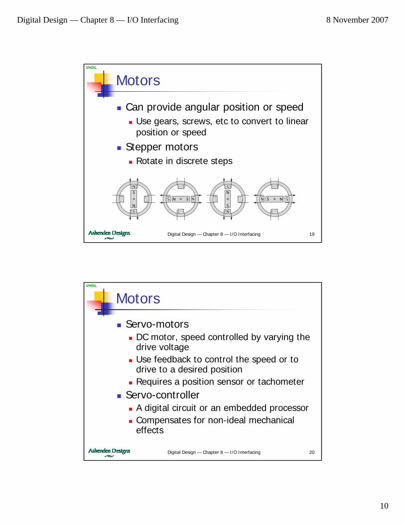
Motors
Can provide angular position or speedUse gears, screws, etc to convert to linear position or speed
Stepper motorsRotate in discrete steps
N
S
NS N S
N
S
NS
N
S
N
S
N S
Digital Design — Chapter 8 — I/O Interfacing 20
VHDL
Motors
Servo-motorsDC motor, speed controlled by varying the drive voltageUse feedback to control the speed or to drive to a desired positionRequires a position sensor or tachometer
Servo-controllerA digital circuit or an embedded processorCompensates for non-ideal mechanical effects
Digital Design — Chapter 8 — I/O Interfacing 8 November 2007
11
Digital Design — Chapter 8 — I/O Interfacing 21
VHDL
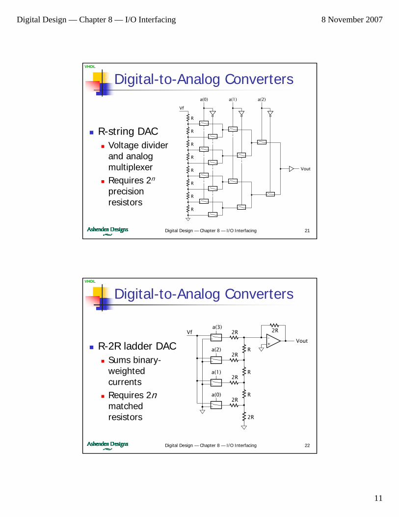
Digital-to-Analog Converters
R-string DACVoltage divider and analog multiplexerRequires 2n
precision resistors
Vf
R
R
R
R
R
R
R
R
Vout
a(0) a(1) a(2)
Digital Design — Chapter 8 — I/O Interfacing 22
VHDL
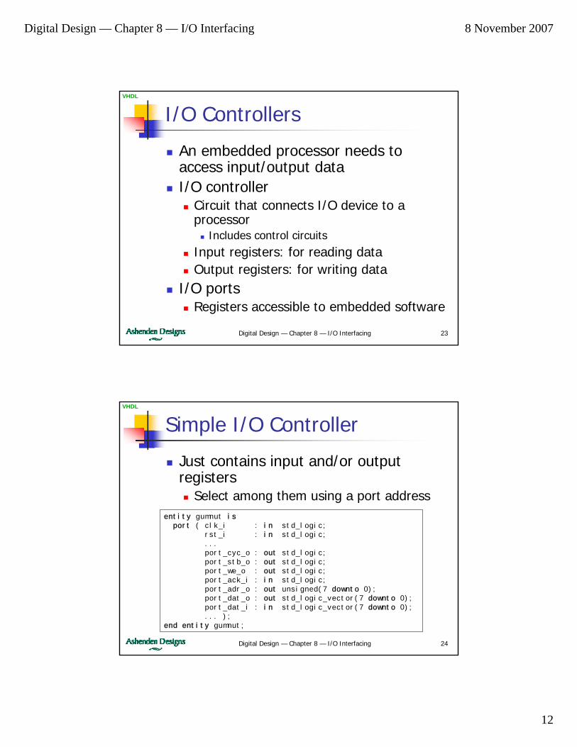
Digital-to-Analog Converters
R-2R ladder DACSums binary-weighted currentsRequires 2nmatched resistors
Vf 2R
R
2R
R
R
2R
2R
2R
2R
Vout
a(3)
a(2)
a(1)
a(0)
+–
Digital Design — Chapter 8 — I/O Interfacing 8 November 2007
12
Digital Design — Chapter 8 — I/O Interfacing 23
VHDL
I/O Controllers
An embedded processor needs to access input/output dataI/O controller
Circuit that connects I/O device to a processor
Includes control circuitsInput registers: for reading dataOutput registers: for writing data
I/O portsRegisters accessible to embedded software
Digital Design — Chapter 8 — I/O Interfacing 24
VHDL
Simple I/O Controller
Just contains input and/or output registers
Select among them using a port addressentity gumnut isport ( clk_i : in std_logic;
rst_i : in std_logic;...port_cyc_o : out std_logic;port_stb_o : out std_logic;port_we_o : out std_logic;port_ack_i : in std_logic;port_adr_o : out unsigned(7 downto 0);port_dat_o : out std_logic_vector(7 downto 0);port_dat_i : in std_logic_vector(7 downto 0);... );
end entity gumnut;
Digital Design — Chapter 8 — I/O Interfacing 8 November 2007
13
Digital Design — Chapter 8 — I/O Interfacing 25
VHDL
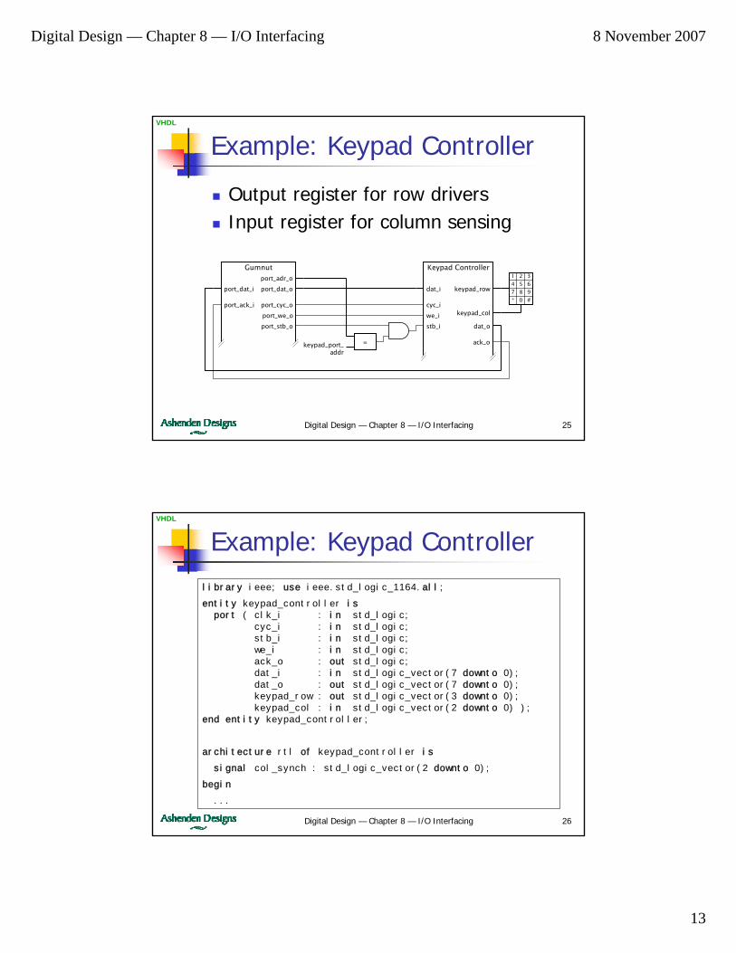
Example: Keypad Controller
Output register for row driversInput register for column sensing
port_dat_i
port_ack_i
port_adr_o
port_we_o
port_cyc_o
Gumnut
port_dat_o
port_stb_o stb_i
dat_i
cyc_i
we_i
Keypad Controller
dat_o
keypad_row
keypad_col
ack_o=keypad_port_addr
1 2 3
4 5 6
7 8 9
* 0 #
Digital Design — Chapter 8 — I/O Interfacing 26
VHDL
Example: Keypad Controllerlibrary ieee; use ieee.std_logic_1164.all;
entity keypad_controller isport ( clk_i : in std_logic;
cyc_i : in std_logic;stb_i : in std_logic;we_i : in std_logic;ack_o : out std_logic;dat_i : in std_logic_vector(7 downto 0);dat_o : out std_logic_vector(7 downto 0);keypad_row : out std_logic_vector(3 downto 0);keypad_col : in std_logic_vector(2 downto 0) );
end entity keypad_controller;
architecture rtl of keypad_controller is
signal col_synch : std_logic_vector(2 downto 0);
begin
...

Digital Design — Chapter 8 — I/O Interfacing 8 November 2007
14
Digital Design — Chapter 8 — I/O Interfacing 27
VHDL
Example: Keypad Controller...
row_reg : process (clk_i) isbeginif rising_edge(clk_i) thenif cyc_i = '1' and stb_i = '1' and we_i = '1' then
keypad_row <= dat_i(3 downto 0);end if;
end if;end process row_reg;
col_synchronizer : process (clk_i) isbeginif rising_edge(clk_i) thendat_o <= "00000" & col_synch;col_synch <= keypad_col;
end if;end process col_synchronizer;
ack_o <= cyc_i and stb_i;
end architecture rtl;
Digital Design — Chapter 8 — I/O Interfacing 28
VHDL
Control/Status Registers
Control registerContains bits that govern operation of the I/O deviceWritten by processor
Status registerContains bits that reflect status of deviceRead by processor
Either or both may be needed in an input or output controller

Digital Design — Chapter 8 — I/O Interfacing 8 November 2007
15
Digital Design — Chapter 8 — I/O Interfacing 29
VHDL
Example: ADC Controller
Successive approximation ADC1 × analog input with sample/hold4 × analog reference voltages
Control registerSelects reference voltageHold input voltage & start ADC
Status registerIs conversion done?
Input data registerConverted data
Digital Design — Chapter 8 — I/O Interfacing 30
VHDL
Example: ADC Controller
D2CEreset
Q2D1 Q1D0 Q0
clk
Y2Y3
D1Y1D0Y0
startreset
doneVf
DoutADC
Vin
clk
0
10
0
Vin
port_dat_o
port_ack_oVf_0
Vf_1
Vf_2
Vf_3
port_dat_i
port_cyc_i
rst_iclk_i
port_adr_i(0)
1
2
7...1port_we_i
port_stb_i
port_cyc_i
port_stb_i
Digital Design — Chapter 8 — I/O Interfacing 8 November 2007
16
Digital Design — Chapter 8 — I/O Interfacing 31
VHDL
Autonomous I/O Controllers
Independently sequence operation of a device
Processor initiates actionsController notifies processor of events, such as data availability, error condition, …
Processor can perform other operations concurrentlyDevice operation not limited by processor performance or load
Digital Design — Chapter 8 — I/O Interfacing 32
VHDL
Example: LCD Module
Rectangular array of pixelsRow and column connectionsController scans rows, activates columns
Image or character data stored in a small memory in the controller
Updated by an attached processor
Digital Design — Chapter 8 — I/O Interfacing 8 November 2007
17
Digital Design — Chapter 8 — I/O Interfacing 33
VHDL
Direct Memory Access (DMA)
For high-speed input or outputProcessor writes starting address to a control registerController transfers data to/from memory autonomouslyNotifies processor on completion/error
Reduces load on processorCommon with accelerators
Digital Design — Chapter 8 — I/O Interfacing 34
VHDL
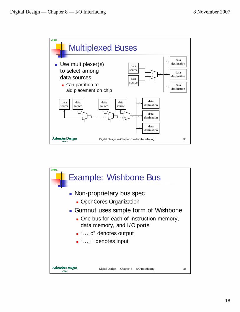
Parallel Buses
Interconnect components in a systemTransfer bits of data in parallel
Conceptual structureAll inputs andoutput connected
In practiceCan’t tiemultiple outputstogether
datasource
datadestination
datasource
datadestination
datadestination
Digital Design — Chapter 8 — I/O Interfacing 8 November 2007
18
Digital Design — Chapter 8 — I/O Interfacing 35
VHDL
Multiplexed Buses
Use multiplexer(s)to select amongdata sources
Can partition toaid placement on chip
datasource
datadestination
datasource
datadestination
datadestination
1
0
1
0
datasource
1
0
datasource
datasource
datadestination
datasource
datadestination
datadestination
0
1
Digital Design — Chapter 8 — I/O Interfacing 36
VHDL
Example: Wishbone Bus
Non-proprietary bus specOpenCores Organization
Gumnut uses simple form of WishboneOne bus for each of instruction memory, data memory, and I/O ports“…_o” denotes output“…_i” denotes input
Digital Design — Chapter 8 — I/O Interfacing 8 November 2007
19
Digital Design — Chapter 8 — I/O Interfacing 37
VHDL
Example: Wishbone Bus
port_dat_i
port_ack_i
port_adr_o
port_we_o
port_cyc_o
Gumnut
port_dat_o
port_stb_o
adr_i(0)
dat_i
cyc_i
we_i
ADC Controller
dat_o
ack_o
stb_i
adr_i(0)
dat_i
cyc_i
we_i
ADC Controller
dat_o
ack_o
stb_i
stb_i
dat_i
cyc_i
we_i
Keypad Controller
dat_o
ack_o
0
1
0
1
0
1
0
1
= 0...1
= 2...3
= 4
0
0
Digital Design — Chapter 8 — I/O Interfacing 38
VHDL
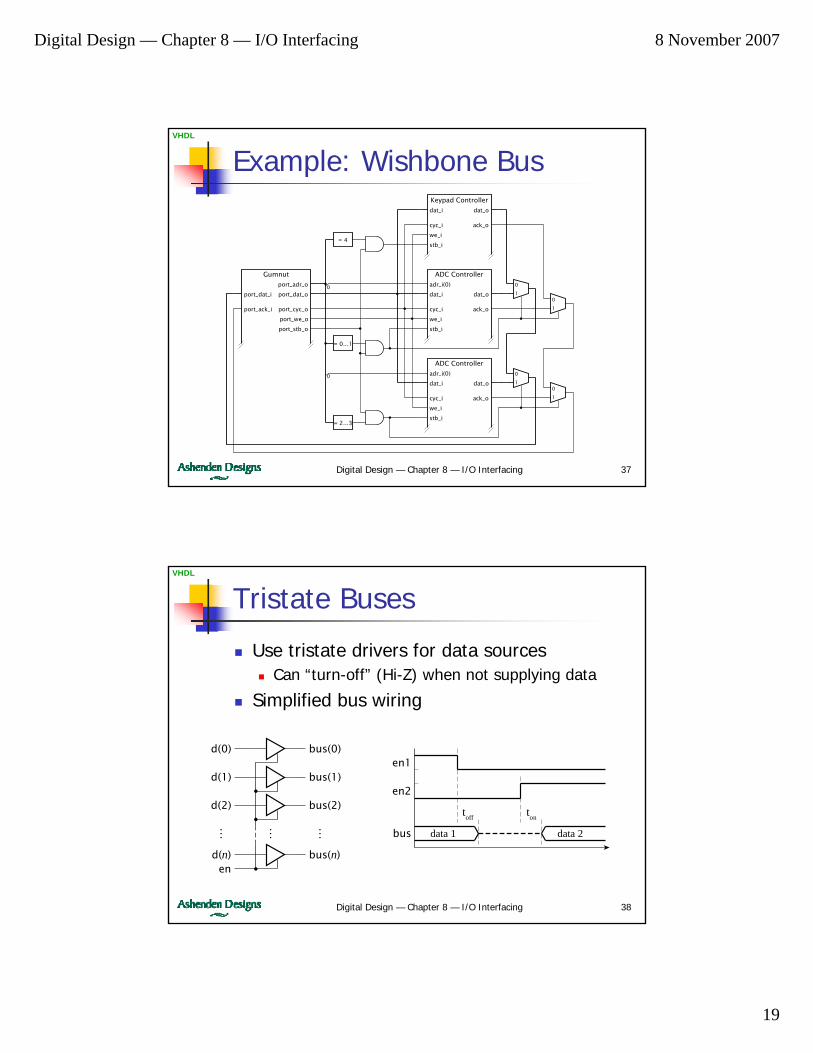
Tristate Buses
Use tristate drivers for data sourcesCan “turn-off” (Hi-Z) when not supplying data
Simplified bus wiring
en2
en1
bus
toff
data 1 data 2
ton
bus(0)d(0)
en
… ……
bus(1)d(1)
bus(2)d(2)
bus(n)d(n)
Digital Design — Chapter 8 — I/O Interfacing 8 November 2007
20
Digital Design — Chapter 8 — I/O Interfacing 39
VHDL
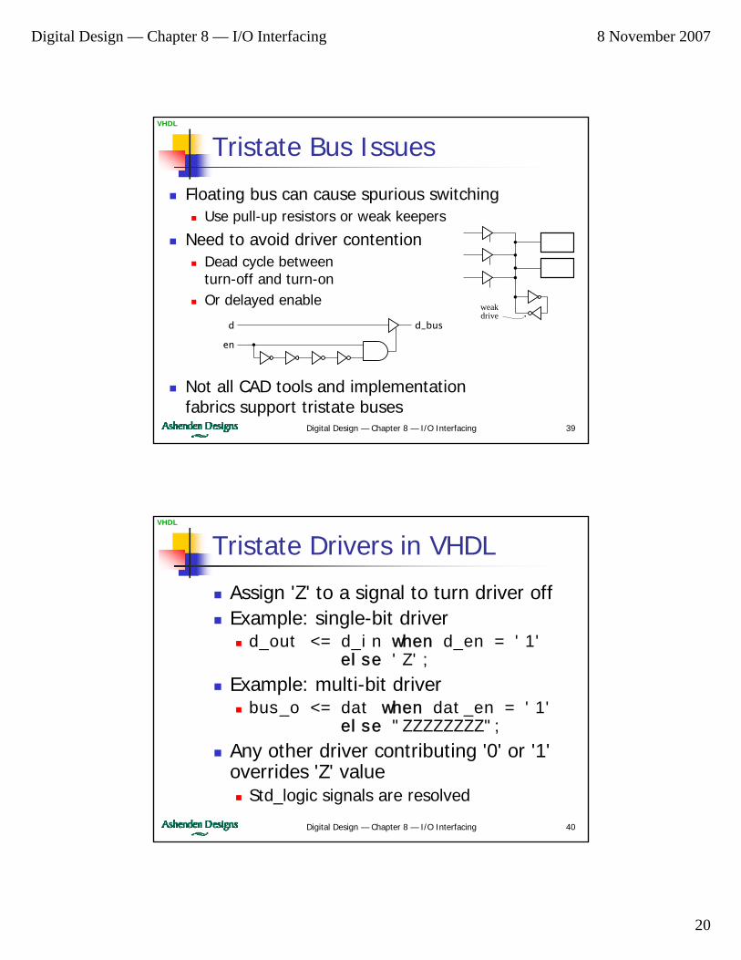
Tristate Bus Issues
Floating bus can cause spurious switchingUse pull-up resistors or weak keepers
Need to avoid driver contentionDead cycle betweenturn-off and turn-onOr delayed enable weak
drived_busd
en
Not all CAD tools and implementationfabrics support tristate buses
Digital Design — Chapter 8 — I/O Interfacing 40
VHDL
Tristate Drivers in VHDL
Assign 'Z' to a signal to turn driver offExample: single-bit driverd_out <= d_in when d_en = '1'
else 'Z';
Example: multi-bit driverbus_o <= dat when dat_en = '1'
else "ZZZZZZZZ";
Any other driver contributing '0' or '1' overrides 'Z' value
Std_logic signals are resolved

Digital Design — Chapter 8 — I/O Interfacing 8 November 2007
21
Digital Design — Chapter 8 — I/O Interfacing 41
VHDL
Example: SN74x16541
y1(0)a1(0)
a1(1)
… … …
a1(7)
en1_1
en1_2
y1(1)
y1(7)
y2(0)a2(0)
a2(1)
… … …
a2(7)
en2_1
en2_2
y2(1)
y2(7)
library ieee; use ieee.std_logic_1164.all;
entity sn74x16541 isport( en1_1, en1_2,en2_1, en2_2 : in std_logic;a1, a2 : in std_logic_vector(7 downto 0);y1, y2 : out std_logic_vector(7 downto 0) );
end entity sn74x16541;
architecture rtl of sn74x16541 isbeginy1 <= a1 when en1_1 = '0' and en1_2 = '0' else
(others => 'Z');y2 <= a2 when en2_1 = '0' and en2_2 = '0' else
(others => 'Z');end architecture rtl;
Digital Design — Chapter 8 — I/O Interfacing 42
VHDL
Unknown Values in VHDL
What if two drivers are turned on?One driving '0', the other driving '1'Resolved value is 'X' — unknownCan test for 'X' during simulation
'Z' and 'X' are not electrical logic levelsNotations for simulation and synthesisReal logic levels are only 0 or 1
Digital Design — Chapter 8 — I/O Interfacing 8 November 2007
22
Digital Design — Chapter 8 — I/O Interfacing 43
VHDL
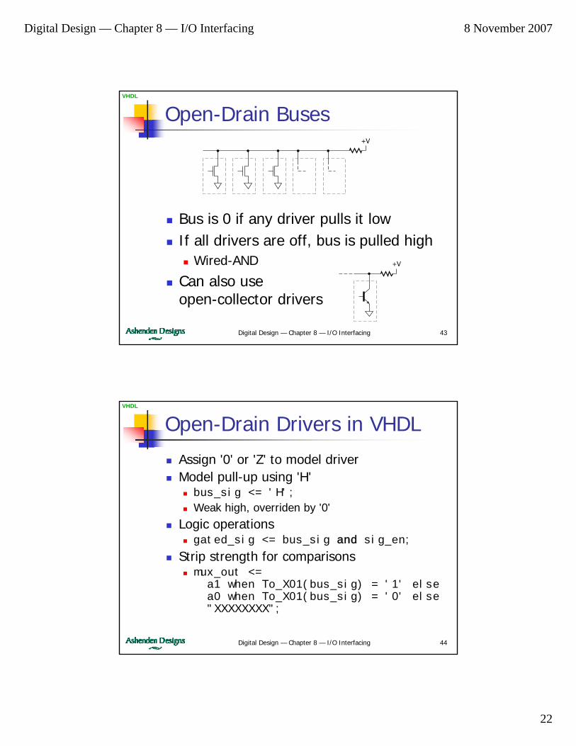
Open-Drain Buses
Bus is 0 if any driver pulls it lowIf all drivers are off, bus is pulled high
Wired-AND
Can also useopen-collector drivers
+V
+V
Digital Design — Chapter 8 — I/O Interfacing 44
VHDL
Open-Drain Drivers in VHDL
Assign '0' or 'Z' to model driverModel pull-up using 'H'
bus_sig <= 'H';
Weak high, overriden by '0'Logic operations
gated_sig <= bus_sig and sig_en;
Strip strength for comparisonsmux_out <=
a1 when To_X01(bus_sig) = '1' elsea0 when To_X01(bus_sig) = '0' else"XXXXXXXX";
Digital Design — Chapter 8 — I/O Interfacing 8 November 2007
23
Digital Design — Chapter 8 — I/O Interfacing 45
VHDL
Bus Protocols
Specification of signals, timing, and sequencing of bus operations
Allows independent design of componentsEnsures interoperability
Standard bus protocolsPCI, VXI, …
For connecting boards in a systemAMBA (ARM), CoreConnect (IBM), Wishbone (Open Cores)
For connecting blocks within a chip
Digital Design — Chapter 8 — I/O Interfacing 46
VHDL
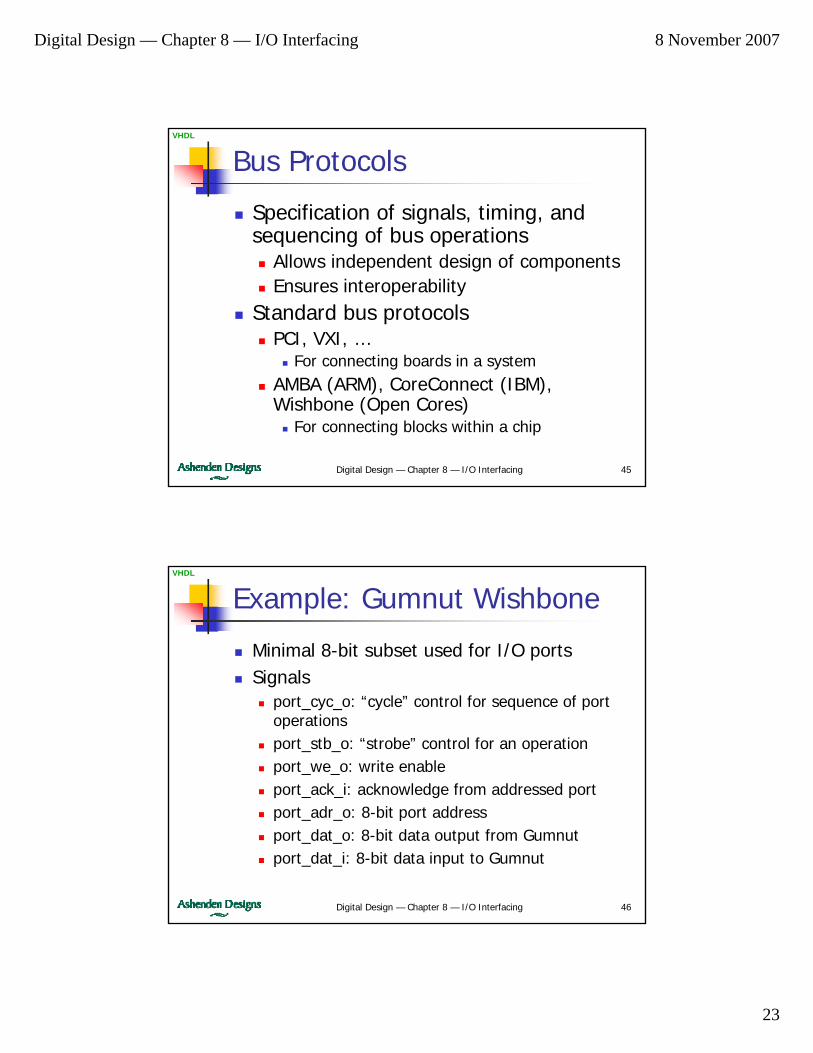
Example: Gumnut Wishbone
Minimal 8-bit subset used for I/O portsSignals
port_cyc_o: “cycle” control for sequence of port operationsport_stb_o: “strobe” control for an operationport_we_o: write enableport_ack_i: acknowledge from addressed portport_adr_o: 8-bit port addressport_dat_o: 8-bit data output from Gumnutport_dat_i: 8-bit data input to Gumnut
Digital Design — Chapter 8 — I/O Interfacing 8 November 2007
24
Digital Design — Chapter 8 — I/O Interfacing 47
VHDL
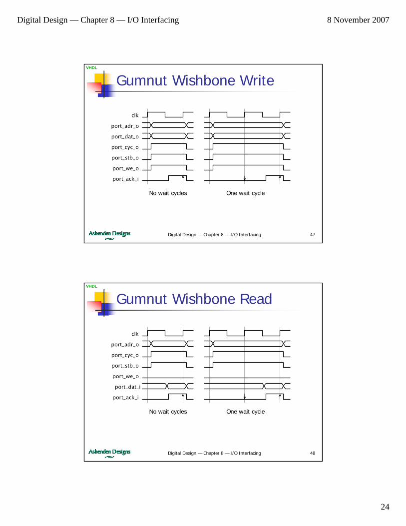
Gumnut Wishbone Write
clk
port_adr_o
port_cyc_o
port_dat_o
port_ack_i
port_stb_o
port_we_o
No wait cycles One wait cycle
Digital Design — Chapter 8 — I/O Interfacing 48
VHDL
clk
port_adr_o
port_cyc_o
port_dat_i
port_ack_i
port_stb_o
port_we_o
Gumnut Wishbone Read
No wait cycles One wait cycle
Digital Design — Chapter 8 — I/O Interfacing 8 November 2007
25
Digital Design — Chapter 8 — I/O Interfacing 49
VHDL
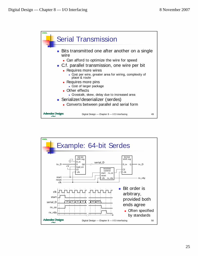
Serial TransmissionBits transmitted one after another on a single wire
Can afford to optimize the wire for speedC.f. parallel transmission, one wire per bit
Requires more wiresCost per wire, greater area for wiring, complexity of place & route
Requires more pinsCost of larger package
Other effectsCrosstalk, skew, delay due to increased area
Serializer/deserializer (serdes)Converts between parallel and serial form
Digital Design — Chapter 8 — I/O Interfacing 50
VHDL
Example: 64-bit Serdes64-bit
shift regD_inD
CEload_en
Q0
clk
64-bitshift reg
D_in
CE
Q
clk
startreset
tx_Dserial_D
rx_D
rx_rdy
clk
clk
startreset
rx_ce
rx_rdy
receivercontrol
+V
rx_rdy
rx_ce
serial_D
start
clk
D0 D1 D62 D63D2 D3
Bit order is arbitrary, provided both ends agree
Often specified by standards
Digital Design — Chapter 8 — I/O Interfacing 8 November 2007
26
Digital Design — Chapter 8 — I/O Interfacing 51
VHDL
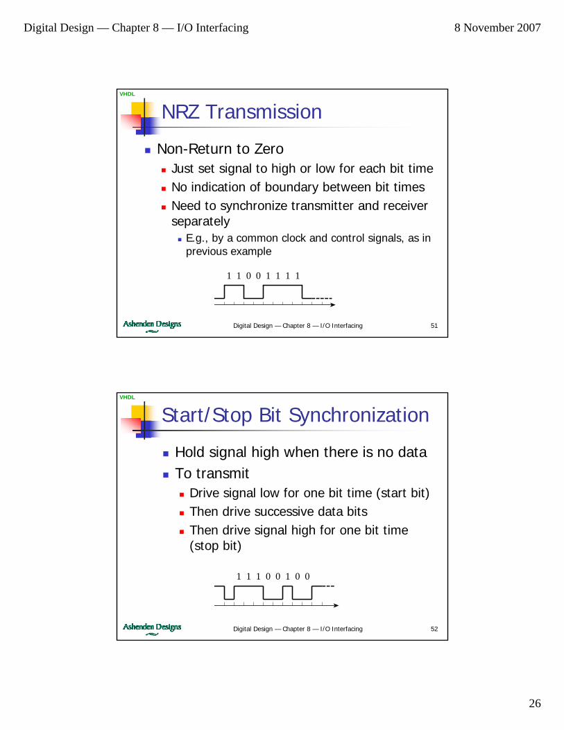
NRZ Transmission
Non-Return to ZeroJust set signal to high or low for each bit timeNo indication of boundary between bit timesNeed to synchronize transmitter and receiver separately
E.g., by a common clock and control signals, as in previous example
1 1 0 0 1 1 1 1
Digital Design — Chapter 8 — I/O Interfacing 52
VHDL
Start/Stop Bit Synchronization
Hold signal high when there is no dataTo transmit
Drive signal low for one bit time (start bit)Then drive successive data bitsThen drive signal high for one bit time (stop bit)
1 1 1 10 0 0 0
Digital Design — Chapter 8 — I/O Interfacing 8 November 2007
27
Digital Design — Chapter 8 — I/O Interfacing 53
VHDL
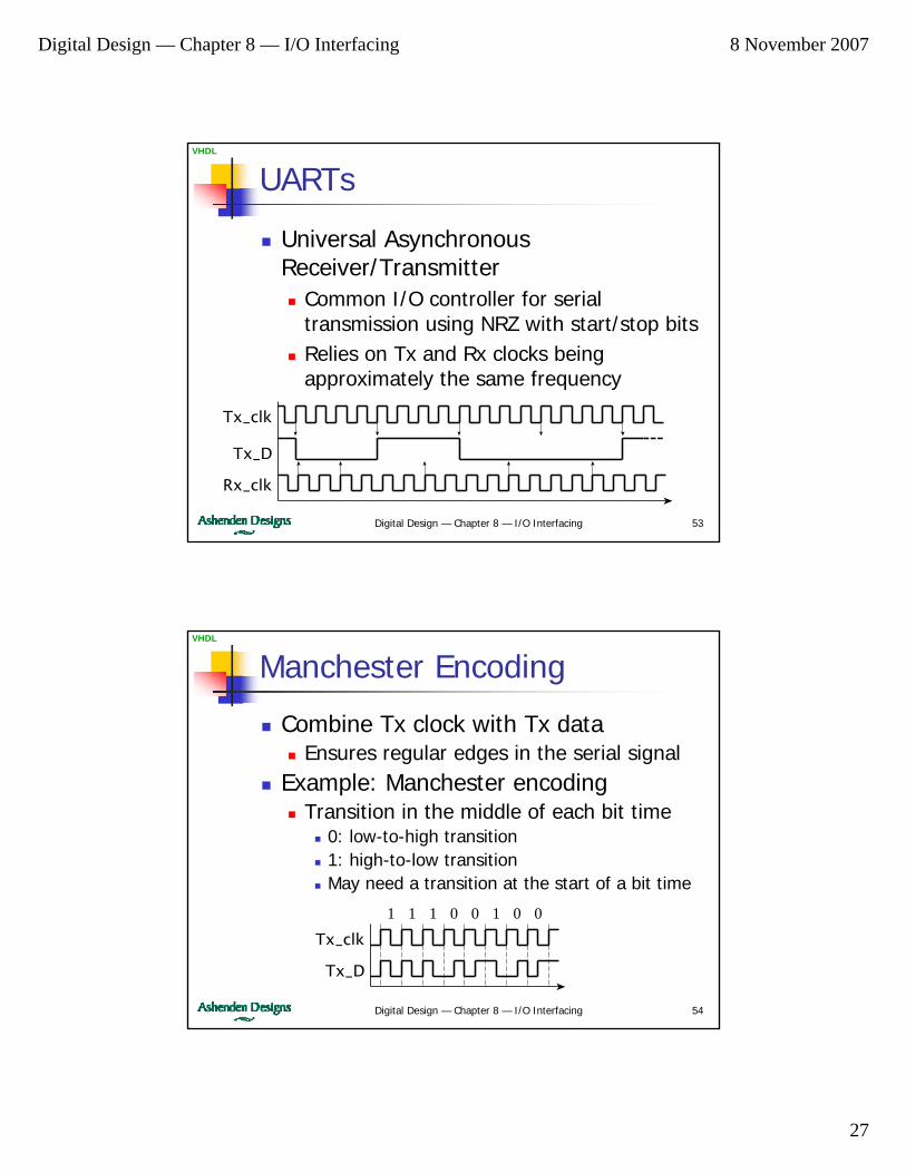
UARTs
Universal Asynchronous Receiver/Transmitter
Common I/O controller for serial transmission using NRZ with start/stop bitsRelies on Tx and Rx clocks being approximately the same frequency
Tx_clk
Tx_D
Rx_clk
Digital Design — Chapter 8 — I/O Interfacing 54
VHDL
Manchester Encoding
Combine Tx clock with Tx dataEnsures regular edges in the serial signal
Example: Manchester encodingTransition in the middle of each bit time
0: low-to-high transition1: high-to-low transitionMay need a transition at the start of a bit time
1 1 1 10 0 0 0
Tx_clk
Tx_D
Digital Design — Chapter 8 — I/O Interfacing 8 November 2007
28
Digital Design — Chapter 8 — I/O Interfacing 55
VHDL
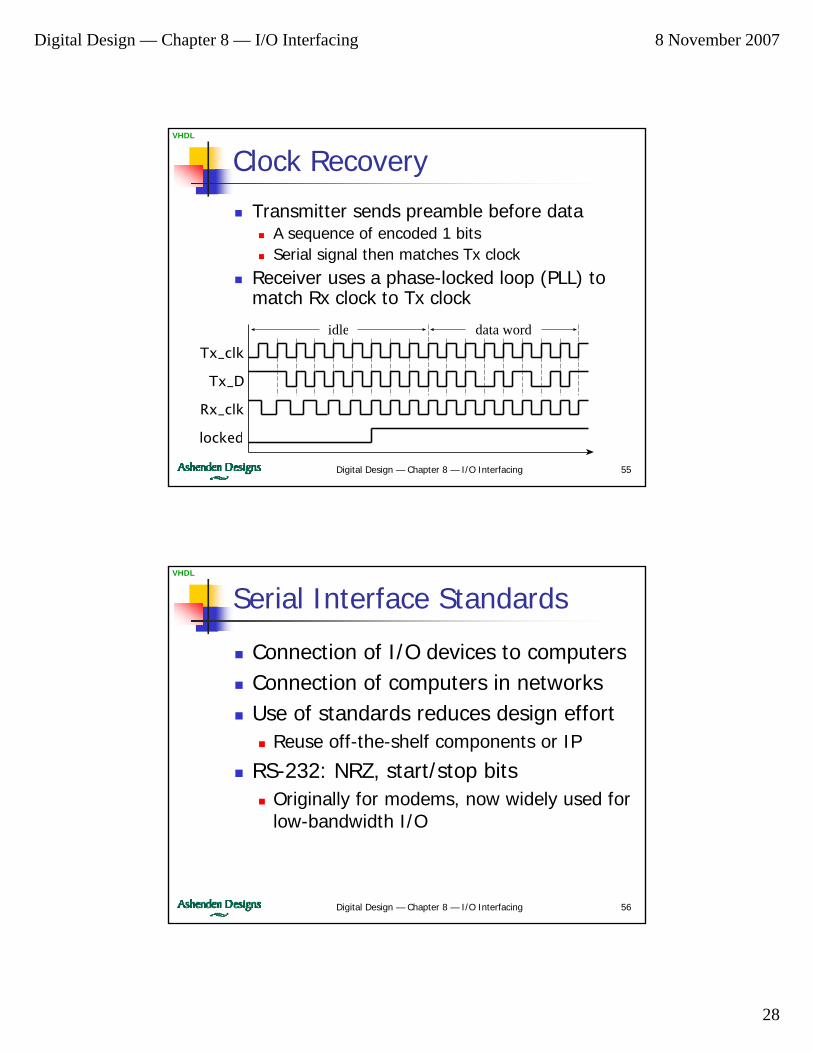
Clock Recovery
Transmitter sends preamble before dataA sequence of encoded 1 bitsSerial signal then matches Tx clock
Receiver uses a phase-locked loop (PLL) to match Rx clock to Tx clock
idle data word
Tx_clk
Tx_D
Rx_clk
locked
Digital Design — Chapter 8 — I/O Interfacing 56
VHDL
Serial Interface Standards
Connection of I/O devices to computersConnection of computers in networksUse of standards reduces design effort
Reuse off-the-shelf components or IP
RS-232: NRZ, start/stop bitsOriginally for modems, now widely used for low-bandwidth I/O
Digital Design — Chapter 8 — I/O Interfacing 8 November 2007
29
Digital Design — Chapter 8 — I/O Interfacing 57
VHDL
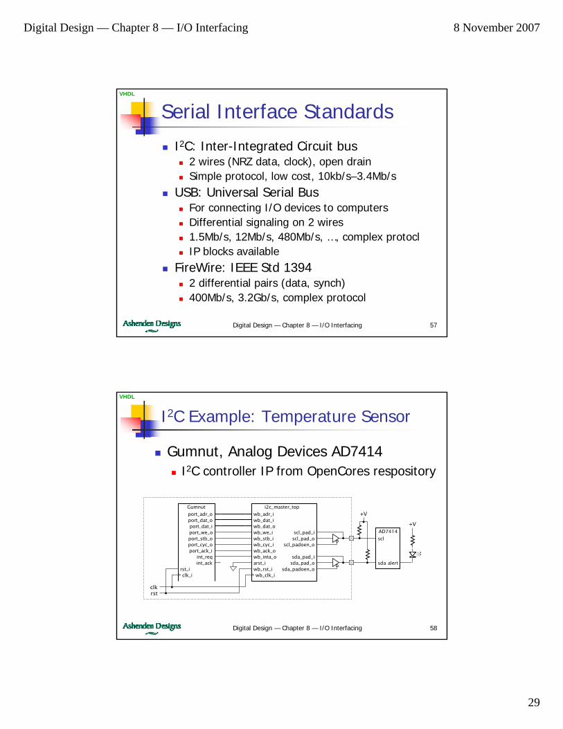
Serial Interface Standards
I2C: Inter-Integrated Circuit bus2 wires (NRZ data, clock), open drainSimple protocol, low cost, 10kb/s–3.4Mb/s
USB: Universal Serial BusFor connecting I/O devices to computersDifferential signaling on 2 wires1.5Mb/s, 12Mb/s, 480Mb/s, …, complex protoclIP blocks available
FireWire: IEEE Std 13942 differential pairs (data, synch)400Mb/s, 3.2Gb/s, complex protocol
Digital Design — Chapter 8 — I/O Interfacing 58
VHDL
I2C Example: Temperature Sensor
Gumnut, Analog Devices AD7414I2C controller IP from OpenCores respository
wb_adr_iwb_dat_iwb_dat_o
wb_rst_iarst_i
wb_we_i
i2c_master_top
wb_stb_iwb_cyc_iwb_ack_owb_inta_o
scl_pad_iscl_pad_o
scl_padoen_o
sda_pad_isda_pad_o
sda_padoen_owb_clk_i
rst_i
Gumnut
port_adr_oport_dat_oport_dat_iport_we_oport_stb_oport_cyc_oport_ack_i
int_reqint_ack
clk_i
scl
AD7414
sda alert
rstclk
+V
+V
Digital Design — Chapter 8 — I/O Interfacing 8 November 2007
30
Digital Design — Chapter 8 — I/O Interfacing 59
VHDL
I/O Software
Use input and output instructions to access I/O controller registersI/O devices interact with the physical world
Software must respond to events when they occurIt must be able schedule activity at specific times or at regular intervalsReal-time behavior
Digital Design — Chapter 8 — I/O Interfacing 60
VHDL
Polling
Software repeatedly reads I/O status to see if an event has occurred
If so, it performs the required actionMultiple controllers
Software executes a polling loop, checking controllers in turn
Advantage: simple I/O controllersDisadvantages
Processor is continually busy, consuming powerDelay in dealing with an event if processor is busy with another event

Digital Design — Chapter 8 — I/O Interfacing 8 November 2007
31
Digital Design — Chapter 8 — I/O Interfacing 61
VHDL
Polling Example
Safety monitor in factory automationGumnut core16 alarm inputs
One per bit in registers at addresses 16 & 170 ⇒ ok, 1 ⇒ abnormal condition
Temp sensor ADC at address 208-bit binary code for °CAbove 50°C is abnormal
Alarm output at address 400 ⇒ ok, 1 ⇒ ring alarm bell
Digital Design — Chapter 8 — I/O Interfacing 62
VHDL
Polling Examplealarm_in_1: equ 16 ; address of alarm_in_1 input registeralarm_in_2: equ 17 ; address of alarm_in_2 input registertemp_in: equ 20 ; address of temp_in input registeralarm_out: equ 40 ; address of alarm_out output registermax_temp: equ 50 ; maximum permissible temperature
poll_loop: inp r1, alarm_in_1sub r0, r1, 0bnz set_alarm ; one or more alarm_in_1 bits setinp r1, alarm_in_2sub r0, r1, 0bnz set_alarm ; one or more alarm_in_2 bits setinp r1, temp_insub r0, r1, max_tempbnc set_alarm ; temp_in > max_tempout r0, alarm_out ; clear alarm_outjmp poll_loop
set_alarm: add r1, r0, 1out r1, alarm_out ; set alarm_out bit 1 to 1jmp poll_loop

Digital Design — Chapter 8 — I/O Interfacing 8 November 2007
32
Digital Design — Chapter 8 — I/O Interfacing 63
VHDL
Interrupts
I/O controller notifies processor when an event occurs
Processor interrupts what it was doingExecutes interrupt service routine
A.k.a. interrupt handler
Then resumes interrupted taskMay enter low-power standby
Some systems prioritize interrupt requestsAllow higher priority events to interrupt service of lower priority events
Digital Design — Chapter 8 — I/O Interfacing 64
VHDL
Interrupt MechanismsInterrupt request signalMeans of disabling/enabling interrupts
So processor can execute critical regionsSave processor state on an interrupt
So interrupted task can be resumedOn interrupt, disable further interrupts
Until processor has saved stateFind the handler code for the event
Vector: address of handler, or index into table of handler addresses
Instruction to return from handlerRestoring saved state

Digital Design — Chapter 8 — I/O Interfacing 8 November 2007
33
Digital Design — Chapter 8 — I/O Interfacing 65
VHDL
Gumnut Interrupt Mechanisms
int_req signaldisi and enai instructionsOn interrupt, PC, Z, and C saved in special registersOn interrupt, further interrupts are disabledHandler code starts at address 1
Gumnut sets PC to 1
reti instructionRestores PC, Z, and C from special registers, re-enables interrupts
Digital Design — Chapter 8 — I/O Interfacing 66
VHDL
Interrupt Acknowledgment
Process may not respond immediatelyBut must tell controller when it doesController then deactivates request
To avoid multiple interrupts for one event
Processor acknowledges the requestE.g., int_ack signal on GumnutAlternative: reading a status register
Digital Design — Chapter 8 — I/O Interfacing 8 November 2007
34
Digital Design — Chapter 8 — I/O Interfacing 67
VHDL
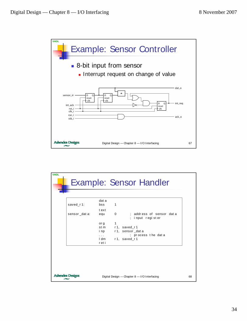
Example: Sensor Controller
8-bit input from sensorInterrupt request on change of value
Dreset
Q
clk
Dreset
Q
clkDreset
Q
clk
≠
dat_o
int_req
ack_o
clk_irst_i
int_ack
cyc_i
stb_i
sensor_in
Digital Design — Chapter 8 — I/O Interfacing 68
VHDL
Example: Sensor Handler
datasaved_r1: bss 1
textsensor_data: equ 0 ; address of sensor data
; input register
org 1stm r1, saved_r1inp r1, sensor_data... ; process the dataldm r1, saved_r1reti

Digital Design — Chapter 8 — I/O Interfacing 8 November 2007
35
Digital Design — Chapter 8 — I/O Interfacing 69
VHDL
Timers
Real-time clock (RTC)Generates periodic interruptsUses a counter to divide system clockControl register for divisor
Interrupt handler can perform periodic tasks
E.g., activate next digit of a scanned display
Digital Design — Chapter 8 — I/O Interfacing 70
VHDL
Example: RTC for Gumnut
10µs timebase, divided by a down counter
Initial count loaded from a registerInterrupt triggered on count value = 0
start_count
E– – – – – – –
count_value
I0
0
1 0 0 0 0 0 0
Output Registers Input RegistersOffset
InterruptEnable
InterruptTriggered
Digital Design — Chapter 8 — I/O Interfacing 8 November 2007
36
Digital Design — Chapter 8 — I/O Interfacing 71
VHDL
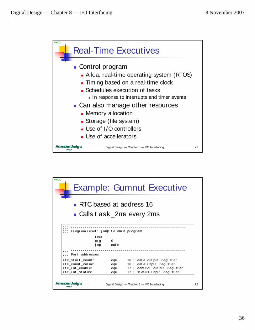
Real-Time Executives
Control programA.k.a. real-time operating system (RTOS)Timing based on a real-time clockSchedules execution of tasks
In response to interrupts and timer events
Can also manage other resourcesMemory allocationStorage (file system)Use of I/O controllersUse of accellerators
Digital Design — Chapter 8 — I/O Interfacing 72
VHDL
Example: Gumnut Executive
RTC based at address 16Calls task_2ms every 2ms
;;; ---------------------------------------------------------;;; Program reset: jump to main program
textorg 0jmp main
;;; ---------------------------------------------------------;;; Port addresses
rtc_start_count: equ 16 ; data output registerrtc_count_value: equ 16 ; data input registerrtc_int_enable: equ 17 ; control output registerrtc_int_status: equ 17 ; status input register
Digital Design — Chapter 8 — I/O Interfacing 8 November 2007
37
Digital Design — Chapter 8 — I/O Interfacing 73
VHDL
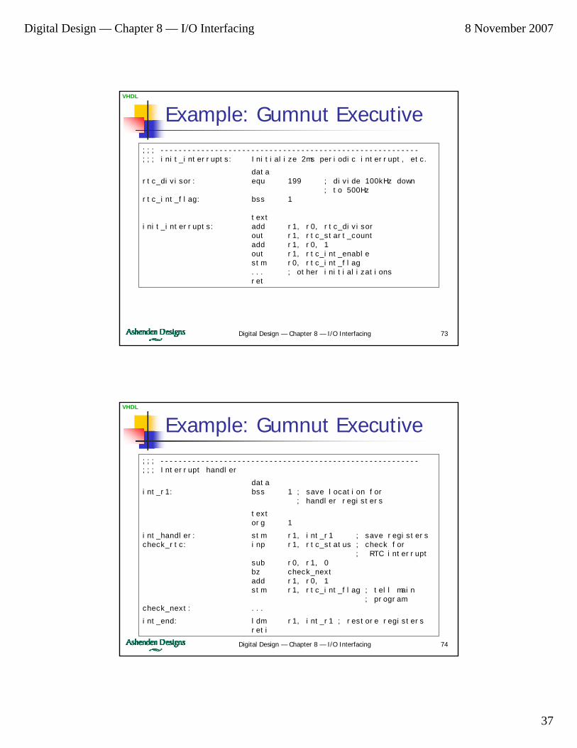
Example: Gumnut Executive;;; ---------------------------------------------------------;;; init_interrupts: Initialize 2ms periodic interrupt, etc.
datartc_divisor: equ 199 ; divide 100kHz down
; to 500Hzrtc_int_flag: bss 1
textinit_interrupts: add r1, r0, rtc_divisor
out r1, rtc_start_countadd r1, r0, 1out r1, rtc_int_enablestm r0, rtc_int_flag... ; other initializationsret
Digital Design — Chapter 8 — I/O Interfacing 74
VHDL
Example: Gumnut Executive;;; ---------------------------------------------------------;;; Interrupt handler
dataint_r1: bss 1 ; save location for
; handler registers
textorg 1
int_handler: stm r1, int_r1 ; save registerscheck_rtc: inp r1, rtc_status ; check for
; RTC interruptsub r0, r1, 0bz check_nextadd r1, r0, 1stm r1, rtc_int_flag ; tell main
; programcheck_next: ...
int_end: ldm r1, int_r1 ; restore registersreti
Digital Design — Chapter 8 — I/O Interfacing 8 November 2007
38
Digital Design — Chapter 8 — I/O Interfacing 75
VHDL
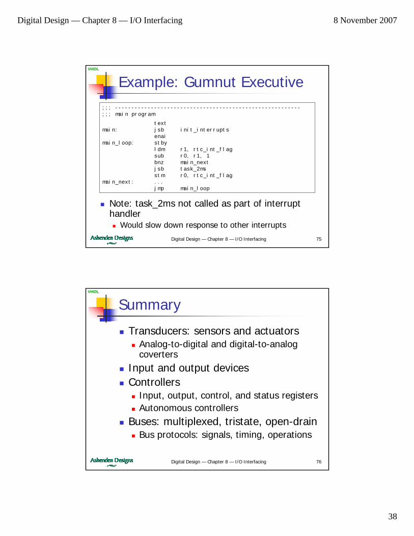
Example: Gumnut Executive;;; ---------------------------------------------------------;;; main program
textmain: jsb init_interrupts
enaimain_loop: stby
ldm r1, rtc_int_flagsub r0, r1, 1bnz main_nextjsb task_2msstm r0, rtc_int_flag
main_next: ...jmp main_loop
Note: task_2ms not called as part of interrupt handler
Would slow down response to other interrupts
Digital Design — Chapter 8 — I/O Interfacing 76
VHDL
Summary
Transducers: sensors and actuatorsAnalog-to-digital and digital-to-analog coverters
Input and output devicesControllers
Input, output, control, and status registersAutonomous controllers
Buses: multiplexed, tristate, open-drainBus protocols: signals, timing, operations
Digital Design — Chapter 8 — I/O Interfacing 8 November 2007
39
Digital Design — Chapter 8 — I/O Interfacing 77
VHDL
Summary
Serial transmissionNRZ, embedded clock
Real-time softwareReacting to I/O and timer eventsPolling, interrupts
Real-time executives