Embed Size (px)
Citation preview
Металлопрокат и трубыпо стандартам
DIN, EN, ASTM
Поставляем металлопрокат по стандарту ASTM A105
Стандарт предоставлен исключительно для ознакомления
Для заказа металлопрокатаили получения консультацииобращайтесь по следующим контактам:
Россия:
Беларусь:
Казахстан:
+7 (495) 134-41-64
+375 (29) 232-97-79
+7 (7172) 72-76-96
www.emk.bz [email protected]
Designation: A105/A105M − 14 Endorsed byManufacturers Standardization Society
of the Valve and Fittings IndustryUsed in USDOE-NE Standards
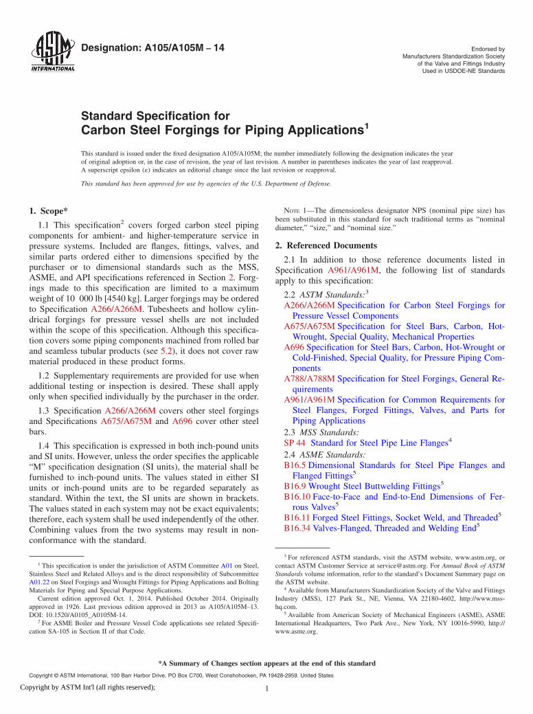
Standard Specification forCarbon Steel Forgings for Piping Applications1
This standard is issued under the fixed designation A105/A105M; the number immediately following the designation indicates the yearof original adoption or, in the case of revision, the year of last revision. A number in parentheses indicates the year of last reapproval.A superscript epsilon (´) indicates an editorial change since the last revision or reapproval.
This standard has been approved for use by agencies of the U.S. Department of Defense.
1. Scope*
1.1 This specification2 covers forged carbon steel pipingcomponents for ambient- and higher-temperature service inpressure systems. Included are flanges, fittings, valves, andsimilar parts ordered either to dimensions specified by thepurchaser or to dimensional standards such as the MSS,ASME, and API specifications referenced in Section 2. Forg-ings made to this specification are limited to a maximumweight of 10 000 lb [4540 kg]. Larger forgings may be orderedto Specification A266/A266M. Tubesheets and hollow cylin-drical forgings for pressure vessel shells are not includedwithin the scope of this specification. Although this specifica-tion covers some piping components machined from rolled barand seamless tubular products (see 5.2), it does not cover rawmaterial produced in these product forms.
1.2 Supplementary requirements are provided for use whenadditional testing or inspection is desired. These shall applyonly when specified individually by the purchaser in the order.
1.3 Specification A266/A266M covers other steel forgingsand Specifications A675/A675M and A696 cover other steelbars.
1.4 This specification is expressed in both inch-pound unitsand SI units. However, unless the order specifies the applicable“M” specification designation (SI units), the material shall befurnished to inch-pound units. The values stated in either SIunits or inch-pound units are to be regarded separately asstandard. Within the text, the SI units are shown in brackets.The values stated in each system may not be exact equivalents;therefore, each system shall be used independently of the other.Combining values from the two systems may result in non-conformance with the standard.
NOTE 1—The dimensionless designator NPS (nominal pipe size) hasbeen substituted in this standard for such traditional terms as “nominaldiameter,” “size,” and “nominal size.”
2. Referenced Documents
2.1 In addition to those reference documents listed inSpecification A961/A961M, the following list of standardsapply to this specification:
2.2 ASTM Standards:3
A266/A266M Specification for Carbon Steel Forgings forPressure Vessel Components
A675/A675M Specification for Steel Bars, Carbon, Hot-Wrought, Special Quality, Mechanical Properties
A696 Specification for Steel Bars, Carbon, Hot-Wrought orCold-Finished, Special Quality, for Pressure Piping Com-ponents
A788/A788M Specification for Steel Forgings, General Re-quirements
A961/A961M Specification for Common Requirements forSteel Flanges, Forged Fittings, Valves, and Parts forPiping Applications
2.3 MSS Standards:SP 44 Standard for Steel Pipe Line Flanges4
2.4 ASME Standards:B16.5 Dimensional Standards for Steel Pipe Flanges and
Flanged Fittings5
B16.9 Wrought Steel Buttwelding Fittings5
B16.10 Face-to-Face and End-to-End Dimensions of Fer-rous Valves5
B16.11 Forged Steel Fittings, Socket Weld, and Threaded5
B16.34 Valves-Flanged, Threaded and Welding End5
1 This specification is under the jurisdiction of ASTM Committee A01 on Steel,Stainless Steel and Related Alloys and is the direct responsibility of SubcommitteeA01.22 on Steel Forgings and Wrought Fittings for Piping Applications and BoltingMaterials for Piping and Special Purpose Applications.
Current edition approved Oct. 1, 2014. Published October 2014. Originallyapproved in 1926. Last previous edition approved in 2013 as A105/A105M–13.DOI: 10.1520/A0105_A0105M-14.
2 For ASME Boiler and Pressure Vessel Code applications see related Specifi-cation SA-105 in Section II of that Code.
3 For referenced ASTM standards, visit the ASTM website, www.astm.org, orcontact ASTM Customer Service at [email protected]. For Annual Book of ASTMStandards volume information, refer to the standard’s Document Summary page onthe ASTM website.
4 Available from Manufacturers Standardization Society of the Valve and FittingsIndustry (MSS), 127 Park St., NE, Vienna, VA 22180-4602, http://www.mss-hq.com.
5 Available from American Society of Mechanical Engineers (ASME), ASMEInternational Headquarters, Two Park Ave., New York, NY 10016-5990, http://www.asme.org.
*A Summary of Changes section appears at the end of this standard
Copyright © ASTM International, 100 Barr Harbor Drive, PO Box C700, West Conshohocken, PA 19428-2959. United States
1Copyright by ASTM Int'l (all rights reserved);
B16.47 Large Diameter Steel Flanges5
2.5 ASME Boiler and Pressure Vessel Code:5
Section IX2.6 API Standards:API-600 Flanged and Butt-Welding-End Steel Gate Valves6
API-602 Compact Design Carbon Steel Gate Valves forRefinery Use6
3. Terminology
3.1 Definitions—For definitions of other terms used in thisspecification, refer to Specification A961/A961M.
3.2 Definitions of Terms Specific to This Standard:3.2.1 heaviest cross-section, n—maximum heat treated
thickness of the production forging.
4. Ordering Information
4.1 See Specification A961/A961M.4.1.1 Additional requirements (see 14.2).
5. General Requirements
5.1 Product furnished to this specification shall conform tothe requirements of Specification A961/A961M, including anysupplementary requirements that are indicated in the purchaseorder. Failure to comply with the requirements of SpecificationA961/A961M constitutes nonconformance with this specifica-tion. In case of a conflict between the requirements of thisspecification and Specification A961/A961M, this specificationshall prevail.
5.2 Except as permitted by Section 6 in SpecificationA961/A961M, the finished product shall be a forging asdefined in the Terminology Section of Specification A788/A788M.
6. Heat Treatment
6.1 Heat treatment is not a mandatory requirement of thisspecification except for the following piping components:
6.1.1 Flanges above Class 300,7
6.1.2 Flanges of special design where the design pressure atthe design temperature exceeds the pressure-temperature rat-ings of Class 300, Group 1.1,
6.1.3 Flanges of special design where the design pressure ordesign temperature are not known,
6.1.4 Piping components other than flanges which meetboth of the following criteria: (1) over NPS 4 and (2) aboveClass 300, and
6.1.5 Piping components of Special Class8 other thanflanges which meet both of the following criteria: (1) over NPS4 and (2) when the working pressure at the operating tempera-ture exceeds the tabulated values for Special Class 300, Group1.1.
6.2 Heat treatment, when required by 6.1 shall be annealing,normalizing, or normalizing and tempering or quenching andtempering in accordance with Specification A961/A961M.
6.2.1 Quenching shall consist of either (1) fully austenitiz-ing the forgings followed by quenching in a suitable liquidmedium or (2) using a multiple stage procedure whereby theforgings are first fully austenitized and rapidly cooled, thenreheated to partially reaustenitize, followed by quenching in asuitable liquid medium. All quenched forgings shall be tem-pered as prescribed in Specification A961/A961M.
7. Chemical Composition
7.1 The steel shall conform to the chemical requirementsspecified in Table 1.
7.2 Steels to which lead has been added shall not be used.
8. Mechanical Properties
8.1 The material shall conform to the mechanical propertyrequirements prescribed in Table 2 and Table 3.
8.2 For normalized, normalized and tempered, or quenchedand tempered forgings, the central axis of the test specimenshall be taken at least 1⁄4 T from the nearest surface as-heat-treated, where T is the maximum heat-treated thickness of therepresented forging. In addition, for quenched and temperedforgings, the midlength of the test specimen shall be at least Tfrom all other surfaces as-heat-treated, exclusive of the Tdimension surfaces. When section thickness does not permitthis positioning, the test specimen shall be positioned as near aspossible to the prescribed location.
8.3 Tension Tests:8.3.1 One tension test shall be made for each heat of
as-forged components.8.3.2 One tension test shall be made from each heat-treating
charge. If more than one heat is included in such a charge, eachheat shall be tested.
8.3.2.1 When forgings of different shapes are included in thesame heat-treating charge, the test specimen shall be obtainedfrom the heaviest cross-section of the thickest forging, exceptfor hubbed flanges (see 8.3.3). The test specimen shall repre-sent all forgings from the same heat and heat-treating chargewhose maximum thicknesses do not exceed the thickness of thetest forging.
6 Available from American Petroleum Institute (API), 1220 L. St., NW,Washington, DC 20005-4070, http://www.api.org.
7 For definition of Class 300, see ASME B16.5.8 For definition of special class, see ASME B16.34.
TABLE 1 Chemical Requirements
NOTE 1—For each reduction of 0.01 % below the specified carbonmaximum (0.35 %), an increase of 0.06 % manganese above the specifiedmaximum (1.05 %) will be permitted up to a maximum of 1.65 %.
Element Composition, %
Carbon 0.35 maxManganese 0.60–1.05Phosphorus 0.035 maxSulfur 0.040 maxSilicon 0.10–0.35Copper 0.40 maxA
Nickel 0.40 maxA
Chromium 0.30 maxA,B
Molybdenum 0.12 maxA,B
Vanadium 0.08 maxA The sum of copper, nickel, chromium, molybdenum and vanadium shall notexceed 1.00 %.B The sum of chromium and molybdenum shall not exceed 0.32 %.
A105/A105M − 14
2Copyright by ASTM Int'l (all rights reserved);
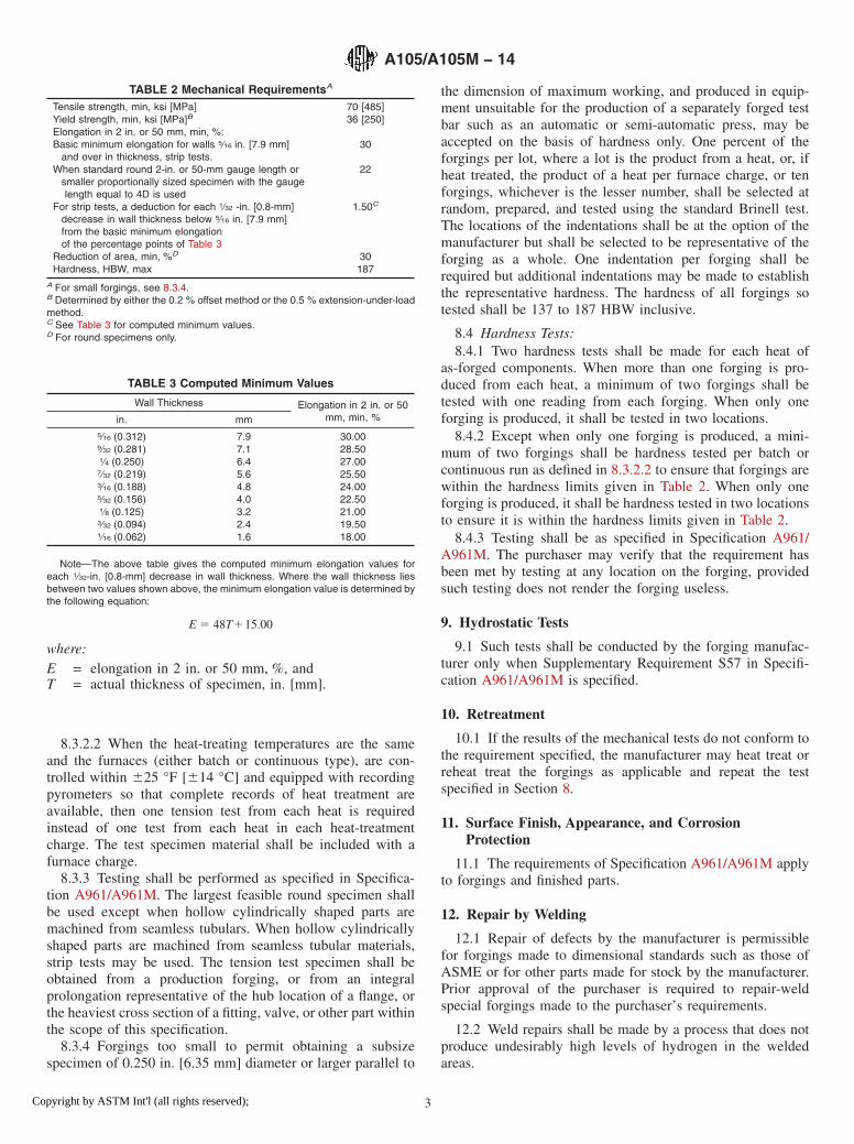
8.3.2.2 When the heat-treating temperatures are the sameand the furnaces (either batch or continuous type), are con-trolled within 625 °F [614 °C] and equipped with recordingpyrometers so that complete records of heat treatment areavailable, then one tension test from each heat is requiredinstead of one test from each heat in each heat-treatmentcharge. The test specimen material shall be included with afurnace charge.
8.3.3 Testing shall be performed as specified in Specifica-tion A961/A961M. The largest feasible round specimen shallbe used except when hollow cylindrically shaped parts aremachined from seamless tubulars. When hollow cylindricallyshaped parts are machined from seamless tubular materials,strip tests may be used. The tension test specimen shall beobtained from a production forging, or from an integralprolongation representative of the hub location of a flange, orthe heaviest cross section of a fitting, valve, or other part withinthe scope of this specification.
8.3.4 Forgings too small to permit obtaining a subsizespecimen of 0.250 in. [6.35 mm] diameter or larger parallel to
the dimension of maximum working, and produced in equip-ment unsuitable for the production of a separately forged testbar such as an automatic or semi-automatic press, may beaccepted on the basis of hardness only. One percent of theforgings per lot, where a lot is the product from a heat, or, ifheat treated, the product of a heat per furnace charge, or tenforgings, whichever is the lesser number, shall be selected atrandom, prepared, and tested using the standard Brinell test.The locations of the indentations shall be at the option of themanufacturer but shall be selected to be representative of theforging as a whole. One indentation per forging shall berequired but additional indentations may be made to establishthe representative hardness. The hardness of all forgings sotested shall be 137 to 187 HBW inclusive.
8.4 Hardness Tests:8.4.1 Two hardness tests shall be made for each heat of
as-forged components. When more than one forging is pro-duced from each heat, a minimum of two forgings shall betested with one reading from each forging. When only oneforging is produced, it shall be tested in two locations.
8.4.2 Except when only one forging is produced, a mini-mum of two forgings shall be hardness tested per batch orcontinuous run as defined in 8.3.2.2 to ensure that forgings arewithin the hardness limits given in Table 2. When only oneforging is produced, it shall be hardness tested in two locationsto ensure it is within the hardness limits given in Table 2.
8.4.3 Testing shall be as specified in Specification A961/A961M. The purchaser may verify that the requirement hasbeen met by testing at any location on the forging, providedsuch testing does not render the forging useless.
9. Hydrostatic Tests
9.1 Such tests shall be conducted by the forging manufac-turer only when Supplementary Requirement S57 in Specifi-cation A961/A961M is specified.
10. Retreatment
10.1 If the results of the mechanical tests do not conform tothe requirement specified, the manufacturer may heat treat orreheat treat the forgings as applicable and repeat the testspecified in Section 8.
11. Surface Finish, Appearance, and CorrosionProtection
11.1 The requirements of Specification A961/A961M applyto forgings and finished parts.
12. Repair by Welding
12.1 Repair of defects by the manufacturer is permissiblefor forgings made to dimensional standards such as those ofASME or for other parts made for stock by the manufacturer.Prior approval of the purchaser is required to repair-weldspecial forgings made to the purchaser’s requirements.
12.2 Weld repairs shall be made by a process that does notproduce undesirably high levels of hydrogen in the weldedareas.
TABLE 2 Mechanical RequirementsA
Tensile strength, min, ksi [MPa] 70 [485]Yield strength, min, ksi [MPa]B 36 [250]Elongation in 2 in. or 50 mm, min, %:Basic minimum elongation for walls 5⁄16 in. [7.9 mm]
and over in thickness, strip tests.30
When standard round 2-in. or 50-mm gauge length orsmaller proportionally sized specimen with the gaugelength equal to 4D is used
22
For strip tests, a deduction for each 1⁄32 -in. [0.8-mm]decrease in wall thickness below 5⁄16 in. [7.9 mm]from the basic minimum elongationof the percentage points of Table 3
1.50C
Reduction of area, min, %D 30Hardness, HBW, max 187
A For small forgings, see 8.3.4.B Determined by either the 0.2 % offset method or the 0.5 % extension-under-loadmethod.C See Table 3 for computed minimum values.D For round specimens only.
TABLE 3 Computed Minimum Values
Wall Thickness Elongation in 2 in. or 50mm, min, %in. mm
5⁄16 (0.312) 7.9 30.009⁄32 (0.281) 7.1 28.501⁄4 (0.250) 6.4 27.007⁄32 (0.219) 5.6 25.503⁄16 (0.188) 4.8 24.005⁄32 (0.156) 4.0 22.501⁄8 (0.125) 3.2 21.003⁄32 (0.094) 2.4 19.501⁄16 (0.062) 1.6 18.00
Note—The above table gives the computed minimum elongation values foreach 1⁄32-in. [0.8-mm] decrease in wall thickness. Where the wall thickness liesbetween two values shown above, the minimum elongation value is determined bythe following equation:
E 5 48T115.00
where:E = elongation in 2 in. or 50 mm, %, andT = actual thickness of specimen, in. [mm].
A105/A105M − 14
3Copyright by ASTM Int'l (all rights reserved);
12.3 All forgings repaired by welding shall be post-weldheat treated between 1100 °F [593 °C] and the lower transfor-mation temperature for a minimum of 1⁄2 h ⁄in. [1⁄2 h/25.4 mm]of maximum section thickness, or alternatively annealed,normalized and tempered, or quenched and tempered. If theforging was not previously heat treated, the original temperingtemperature was exceeded, or the forging was fully heat treatedin the post weld cycle, then the forging shall be tested inaccordance with Section 8 on completion of the cycle.
12.4 The mechanical properties of the procedure-qualification weldment shall, when tested in accordance withSection IX of the ASME Boiler and Pressure Vessel Code,conform with the requirements listed in Table 2 for the thermalcondition of repair-welded forgings.
13. Rejection and Rehearing
13.1 Each forging that develops injurious defects duringshop working or application shall be rejected and the manu-facturer notified.
14. Certification
14.1 Identification Marking—For forgings made to specifieddimensions, when agreed upon by the purchaser, and forforgings made to dimensional standards, application of identi-fication marks as required in Specification A961/A961M shallbe the certification that the forgings have been furnished inaccordance with the requirements of this specification.
14.2 Test Reports—The manufacturer shall also provide thefollowing, where applicable:
14.2.1 Type heat treatment, Section 6,14.2.2 Tensile property results, Section 8 (Table 2), report
the yield strength and tensile strength, in ksi [MPa], elongationand reduction in area, in percent; and, if longitudinal striptension specimens are used, report the width of the gaugelength,
14.2.3 Chemical analysis results, Section 7 (Table 1), re-ported results shall be to the same number of significant figuresas the limits specified in Table 1 for that element.
14.2.4 Hardness results, Section 8 (Table 2), a minimum oftwo readings, and
14.2.5 Any supplementary testing required by the purchaseorder.
15. Product Marking
15.1 In addition to marking requirements of SpecificationA961/A961M, the following additional marking requirementsshall apply:
15.1.1 If the forgings have been quenched and tempered, theletters “QT” shall be stamped on the forgings following thisspecification number.
15.1.2 Forgings repaired by welding shall be marked withthe letter “W” following this specification number.
15.1.3 Plugs and bushings furnished to ASME B16.11requirements are not required to be marked. Other partsordered with no marking are by agreement between thepurchaser and manufacturer.
15.1.4 When agreed upon between the purchaser and manu-facturer and specified in the order, the markings shall bepainted or stenciled on the fitting or stamped on a metal orplastic tag which shall be securely attached to the fitting.
15.2 Bar Coding—In addition to the requirements inSpecification A961/A961M, bar coding is acceptable as asupplemental identification method. The purchaser mayspecify in the order a specific bar coding system to be used.The bar coding system, if applied at the discretion of thesupplier, should be consistent with one of the publishedindustry standards for bar coding. If used on small parts, thebar code may be applied to the box or a substantially appliedtag.
16. Keywords
16.1 pipe fittings, steel; piping applications; pressure con-taining parts; steel flanges; steel forgings, carbon; steel valves;temperature service applications, elevated; temperature serviceapplications, high
SUPPLEMENTARY REQUIREMENTS
The following supplementary requirements shall apply only when specified by the purchaser in theinquiry, contract, and order.
S1. Hardness
S1.1 The purchaser may check the hardness of any or allforgings supplied at any location on the forging and thehardness shall be 137 to 187 HBW. All forgings not within thespecified hardness range shall be rejected.
S2. Heat Treatment
S2.1 All forgings shall be heat treated as specified by thepurchaser.
S2.2 When forgings not requiring heat treatment by 6.1 aresupplied heat treated by purchaser request, the basis fordetermining conformance with Table 2 and Table 3 shall behardness testing per 8.4 and either (1) tensile testing of heattreated forgings per 8.2, or (2) tensile tests from as-forgedforgings or separately forged test blanks, as agreed uponbetween the supplier and purchaser.
S2.3 When test reports are required, and tensile test resultswere obtained from as-forged forgings or as-forged test blanks,it shall be so indicated on the test report.
A105/A105M − 14
4Copyright by ASTM Int'l (all rights reserved);
S2.4 In addition to the marking required by Section 15, thisspecification shall be followed by the letter: A for annealed, Nfor normalized, NT for normalized and tempered, or QT forquenched and tempered, as appropriate.
S3. Marking Small Forgings
S3.1 For small products where the space for marking is lessthan 1 in. [25 mm] in any direction, test reports are mandatoryand marking may be restricted to only such symbols or codesas are necessary to identify the parts with test reports.
S3.2 When the configuration or size does not permit mark-ing directly on the forging, the marking method shall be amatter of agreement between the manufacturer and the pur-chaser.
S4. Carbon Equivalent
S4.1 The maximum carbon equivalent, based on heatanalysis, shall be 0.47 for forgings with a maximum sectionthickness of 2 in. or less, and 0.48 for forgings with amaximum section thickness of greater than 2 in.
S4.2 Determine the carbon equivalent (CE) as follows:
CE 5 C1Mn/61~Cr1Mo1V!/51~Ni1Cu!/15
S4.3 A lower maximum carbon equivalent may be agreedupon between the supplier and the purchaser.
SUMMARY OF CHANGES
Committee A01 has identified the location of selected changes to this specification since the last issue,A105/A105M–13, that may impact the use of this specification. (Approved October 1, 2014)
(1) Added Section 11 on Appearance, Surface Protection, andCorrosion Protection.
Committee A01 has identified the location of selected changes to this specification since the last issue,A105/A105M–12, that may impact the use of this specification. (Approved October 1, 2013)
(1) Revised 8.2 to clarify test specimen location.(2) Revised 8.3.2 to address testing requirements for differentsize forgings in the same heat-treatment charge, to add clari-fication concerning the location for removal of test specimens,and moves mandatory Note 2 into the text.
(3) Revised Sections 14 and 15 on certification and marking.
ASTM International takes no position respecting the validity of any patent rights asserted in connection with any item mentionedin this standard. Users of this standard are expressly advised that determination of the validity of any such patent rights, and the riskof infringement of such rights, are entirely their own responsibility.
This standard is subject to revision at any time by the responsible technical committee and must be reviewed every five years andif not revised, either reapproved or withdrawn. Your comments are invited either for revision of this standard or for additional standardsand should be addressed to ASTM International Headquarters. Your comments will receive careful consideration at a meeting of theresponsible technical committee, which you may attend. If you feel that your comments have not received a fair hearing you shouldmake your views known to the ASTM Committee on Standards, at the address shown below.
This standard is copyrighted by ASTM International, 100 Barr Harbor Drive, PO Box C700, West Conshohocken, PA 19428-2959,United States. Individual reprints (single or multiple copies) of this standard may be obtained by contacting ASTM at the aboveaddress or at 610-832-9585 (phone), 610-832-9555 (fax), or [email protected] (e-mail); or through the ASTM website(www.astm.org). Permission rights to photocopy the standard may also be secured from the Copyright Clearance Center, 222Rosewood Drive, Danvers, MA 01923, Tel: (978) 646-2600; http://www.copyright.com/
A105/A105M − 14
5Copyright by ASTM Int'l (all rights reserved);


![Total Solution for Oil and Gas Testing [ZH] · 2019-03-20 · astm d3710 astm d7096 astm d5399 astm d2887 astm d5442 astm d7213 astm d6417 astm d6352 astm d5307 astm d7500 astm d7169](https://img.pdfslide.tips/doc/110x75/5e70c2f4b4ab9c1c733fd110/total-solution-for-oil-and-gas-testing-zh-2019-03-20-astm-d3710-astm-d7096-astm.jpg)