Embed Size (px)
Citation preview

7/27/2019 Dip Flowcon
http://slidepdf.com/reader/full/dip-flowcon 1/4
FlAB/ABV
The ’’adjustable’’ automatic
ow control valves

7/27/2019 Dip Flowcon
http://slidepdf.com/reader/full/dip-flowcon 2/4
The FlowCon AB and ABV automatic
balancing valves are designed for
balancing heating and air-conditioning
terminal units by providing a constant
flow rate with the added feature of being
adjustable.
The AB / ABV automatic balancingvalves contain an internal composite flow
control cartridge which keeps the flow
rate constant, even with system pressure
conditions changing.
The main difference between these and
other automatic balancing valves is that
each flow control cartridge can be easily
removed and adjusted to one of eight
different flow rates.
There are 14 different adjustable
cartridges, totalling nearly 100 different
flow rates available in sizes 15mm
through 40mm. The adjustable
feature, along with the built-
in ball valve, enables
the contractor or
maintenance
engineer to
easily change
the flow rate
to the terminalunit on the job
site or after
installation.
Features and Benefits
- Automatic balancing, the correct
flow rate for each circuit is achieved
automatically.
- Dynamic balancing, the correct flow
rate is maintained as each valve
compensates for pressure fluctuations in
the system.- Field adjustable, flow rate can be
changed on demand.
- Elimination of branch or »partner«
balancing valves (fewer total valves
used in each project).
- Easily accessible cartridge for flow
rate adjustment or maintenance.
- Accuracy of +/- 10%.
- Built-in isolation ball valve.
- Pressure / temperature measurement
plugs for verifying operating pressure
differential range or checking ∆T across
the coil.
- Double union end connection for ease
of installation and wide selection of end
fittings.
Each cartridge is easily
adjusted.
Dynamic Balancing Valve with internal adjustable ow cartridge
FlowCon
AB and ABV
A total of 14 cartridges available, each
covering a range of flow rates, ensures
the flow rate required is obtainable.
7/27/2019 Dip Flowcon
http://slidepdf.com/reader/full/dip-flowcon 3/4
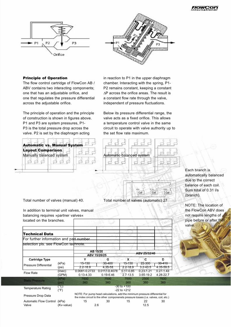
AB 15/20
ABV 15/20/25ABV 25/32/40
Cartridge Type Y G X C D
Pressure Differential(kPa) 15-130 30-400 15-130 22-300 30-410
(psi) 2.2-18.9 4.35-58 2.2-18.9 3.2-43.5 4.35-59.5
Flow Rate(l/sec) 0.0081-0.2733 0.0117-0.4078 0.17-0.85 0.23-1.21 0.27-1.43
(GPM) 0.13-4.33 0.19-6.46 2.7-13.5 3.65-19.2 4.28-22.7
Static Pressure(kPa) 2500 2500 2500 2500 2500
(psi) 360 360 360 360 360
Temperature Rating (°C) -30 to +100(°F) -22 to +212
Pressure Drop DataNOTE: For pump head calculations, add the minimum pressure differential for
the index circuit to the other componenets pressure losses (i.e. valves, coil, etc.)
Automatic Flow Control (kPa) 15 30 15 22 30
Valve (Kv-value) 2.6 12.5
Principle of Operation
The flow control cartridge of FlowCon AB /
ABV contains two interacting components;
one that has an adjustable orifice, and
one that regulates the pressure differential
across the adjustable orifice.
The principle of operation and the principleof construction is shown in figures above.
P1 and P3 are system pressures, P1-
P3 is the total pressure drop across the
valve. P2 is set by the diaphragm acting
in reaction to P1 in the upper diaphragm
chamber. Interacting with the spring, P1-
P2 remains constant, keeping a constant
∆P across the orifice areas. The result is
a constant flow rate through the valve,
independent of pressure fluctuations.
Below its pressure differential range, thevalve acts as a fixed orifice. This allows
a temperature control valve in the same
circuit to operate with valve authority up to
the set flow rate maximum.
Automatic vs. Manual System
Layout Comparison
Manually balanced system
Total number of valves (manual) 40.
In addition to terminal unit valves, manual
balancing requires »partner valves«
located on the branches.
Automatic balanced system
Total number of valves (automatic) 27
Each branch isautomatically balanced
due to the correct
balance of each coil.
Sum total of 0.31 l/s
(branch).
NOTE: The location of
the FlowCon ABV does
not require lengths of
pipe before or after the
valve.
Technical Data
For further information and part number
selection pls. see FlowCon technote.

7/27/2019 Dip Flowcon
http://slidepdf.com/reader/full/dip-flowcon 4/4
Fax: +45 5850 5730
Mail: [email protected]
, #04-04
Fax: +65 6841 8843
Mail: [email protected]
July 2003
Denmark Singapore USA
Cartridge Selection Chart
owX-type
(15-130 kPa)
C-type
(22-300 kPa)
D-type
(30-410 kPa)l/s white red white red white red
0.17 10.23 2 10.26 10.27 10.31 2
0.33 30.36 20.38 4 10.39 20.42 30.44 10.47 40.48 5 30.5 2
0.52 30.54 60.58 40.6 5
0.60 20.62 70.63 40.64 30.66 80.67 5
0.68 60.74 50.76 6 30.78 70.83 4 60.84 80.85 70.9 5
0.93 70.99 8 41.07 6 51.17 71.21 81.28 61.39 71.43 8
Accuracy +/- 10%
Accuracy +/- 10%
owY-TYPE G-TYPE
(15-130 kPa)* (20-130 kPa) (30-400 kPa)* (40-400 kPa)l/s grey* red blue black green grey* red blue black green
0.0081 10.0113 20.0117 10.0175 30.0189 2
0.0222 40.0247 30.0311 50.0325 40.0353 60.0383 70.0431 80.0450 30.0472 50.0528 60.0564 30.0575 40.0597 30.0619 40.0639 70.0669 40.0694 80.0781 40.0908 4
0.0922 50.0958 40.0978 10.1050 60.1136 70.1153 50.1183 20.1194 80.1358 30.1367 60.1369 50.1383 40.1456 70.1461 80.1469 10.1547 50.1614 60.1733 70.1764 60.1797 70.1811 50.1814 80.1861 20.1931 80.2097 30.2164 60.2181 70.2200 80.2306 50.2369 50.2372 60.2414 40.2525 70.2658 60.2689 70.2733 80.2772 8
0.3653 50.3692 60.3919 70.4078 8