Embed Size (px)
Citation preview
3
December 15, 2015
Dissimilar Materials
Weldability Concepts
Dr. Alber Sadek Technology Lead – Materials Engineering
EWI
614.688.5125
4
Introduction
Dissimilar materials welding refers to the joining of: ─ Two different alloy systems (e.g., steel, stainless steel)
─ Materials of different fundamental types
Metals, ceramics, polymers, composite
Ferrous to non-ferrous
─ Materials with different compositions within a particular type (e.g., austenitic stainless steel, ferritic stainless steel, duplex stainless steel, etc.).
Importance to industry: ─ Dissimilar lightweight material welding is used to connect
different metals together for automotive industries
─ Used where an object is subjected to multiple environments in one application such as in chemical and petrochemical industries, power generation, and oil and gas industries
─ Minimize costs of fabrication.
5
Advantages
Each section of the welded component can be optimized for its specific application.
Provide damage tolerance to the overall structure.
Optimize design by matching the correct material to the needed property or behavior.
High performance materials only used where they are absolutely required and provide real benefit.
6
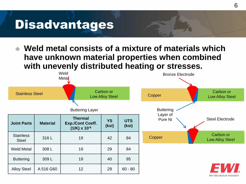
Weld metal consists of a mixture of materials which have unknown material properties when combined with unevenly distributed heating or stresses.
Disadvantages
Buttering Layer
Stainless Steel Carbon or
Low Alloy Steel
Weld
Metal
Buttering
Layer of
Pure Ni
Copper Carbon or
Low Alloy Steel
Steel Electrode
Copper Carbon or
Low Alloy Steel
Bronze Electrode
Joint Parts Material
Thermal
Exp./Cont Coeff.
(1/K) x 10-6
YS
(ksi)
UTS
(ksi)
Stainless
Steel 316 L 19 42 84
Weld Metal 308 L 19 29 84
Buttering 309 L 19 40 95
Alloy Steel A 516 G60 12 29 60 - 80
7
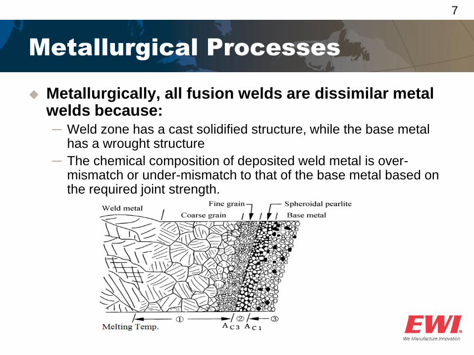
Metallurgical Processes
Metallurgically, all fusion welds are dissimilar metal welds because: ─ Weld zone has a cast solidified structure, while the base metal
has a wrought structure
─ The chemical composition of deposited weld metal is over-mismatch or under-mismatch to that of the base metal based on the required joint strength.
8
Challenges of Welding
Dissimilar Metals
The existence of a transition zone between the metals and the intermetallic compounds formed in the heat affected zone: ─ If there is mutual solubility of the two metals, the dissimilar joints
can be made successfully
─ If there is little or no solubility between the two metals to be joined, the weld joint will not be successful.
The formation of intermetallic compounds and their effects on: ─ Increasing the crack sensitivity
─ Reducing the ductility
─ Increasing the susceptibility to corrosion.
9
Differences in the coefficient of thermal expansion: ─ The residual stresses in welds are generated by the thermal
contraction of the weld metal and the adjacent base metal. As a result, the residual stress distribution and magnitude are not similar across the dissimilar weld joint
─ If these are widely different, there will be internal stresses set up in the inter-critical HAZ leading to service failure.
The difference in melting temperatures, since one metal will be molten and overheated before the other when subjected to the same heat source.
The difference of the electrochemical potential could increase the susceptibility to corrosion at HAZ. If they are far apart on the scale, corrosion can be a serious problem.
Challenges of Welding
Dissimilar Metals
10
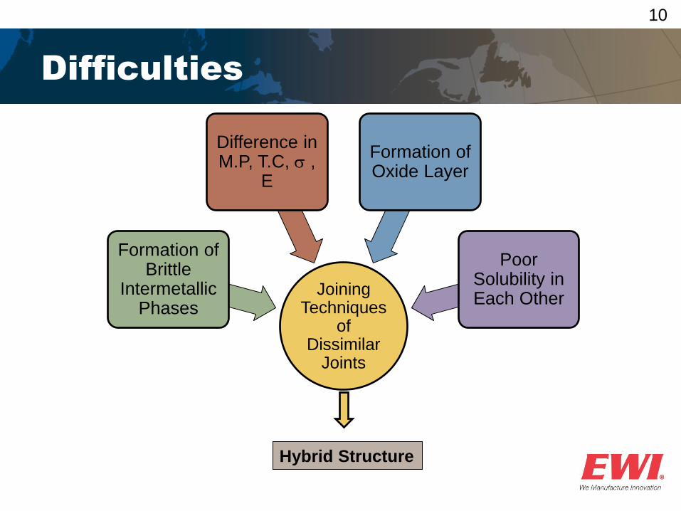
Difficulties
Hybrid Structure
Joining Techniques
of Dissimilar
Joints
Formation of Brittle
Intermetallic Phases
Difference in M.P, T.C, ,
E
Formation of Oxide Layer
Poor Solubility in Each Other
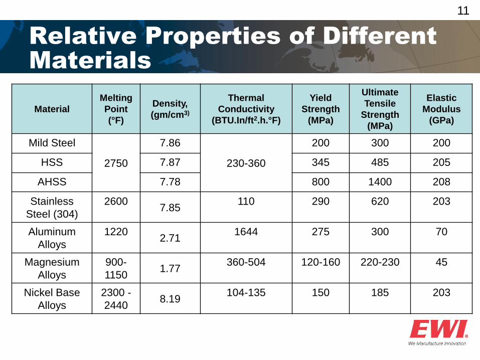
11
Relative Properties of Different
Materials
Material
Melting
Point
(°F)
Density,
(gm/cm3)
Thermal
Conductivity
(BTU.In/ft2.h.°F)
Yield
Strength
(MPa)
Ultimate
Tensile
Strength
(MPa)
Elastic
Modulus
(GPa)
Mild Steel
2750
7.86
230-360
200 300 200
HSS 7.87 345 485 205
AHSS 7.78 800 1400 208
Stainless
Steel (304)
2600 7.85
110 290 620 203
Aluminum
Alloys
1220 2.71
1644 275 300 70
Magnesium
Alloys
900-
1150 1.77
360-504 120-160 220-230 45
Nickel Base
Alloys
2300 -
2440 8.19
104-135 150 185 203
12
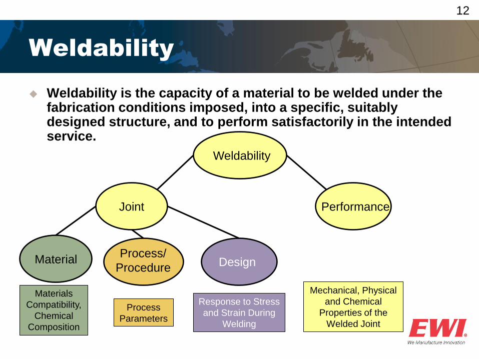
Weldability
Weldability is the capacity of a material to be welded under the fabrication conditions imposed, into a specific, suitably designed structure, and to perform satisfactorily in the intended service.
Materials
Compatibility,
Chemical
Composition
Process
Parameters
Response to Stress
and Strain During
Welding
Joint Performance
Weldability
Process/
Procedure Material Design
Mechanical, Physical
and Chemical
Properties of the
Welded Joint
13
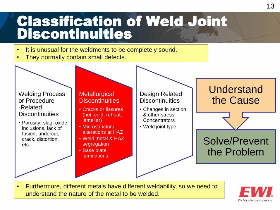
Classification of Weld Joint
Discontinuities
• It is unusual for the weldments to be completely sound.
• They normally contain small defects.
• Furthermore, different metals have different weldability, so we need to
understand the nature of the metal to be welded.
Welding Process or Procedure -Related Discontinuities
• Porosity, slag, oxide inclusions, lack of fusion, undercut, crack, distortion, etc.
Metallurgical Discontinuities
• Cracks or fissures (hot, cold, reheat, lamellar)
• Microstructural alterations at HAZ
• Weld metal & HAZ segregation
• Base plate laminations
Design Related Discontinuities
• Changes in section & other stress Concentrators
• Weld joint type
Solve/Prevent the Problem
Understand the Cause
14
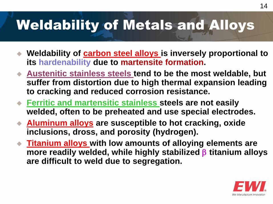
Weldability of Metals and Alloys
Weldability of carbon steel alloys is inversely proportional to its hardenability due to martensite formation.
Austenitic stainless steels tend to be the most weldable, but suffer from distortion due to high thermal expansion leading to cracking and reduced corrosion resistance.
Ferritic and martensitic stainless steels are not easily welded, often to be preheated and use special electrodes.
Aluminum alloys are susceptible to hot cracking, oxide inclusions, dross, and porosity (hydrogen).
Titanium alloys with low amounts of alloying elements are more readily welded, while highly stabilized titanium alloys are difficult to weld due to segregation.

Questions?
Case Studies
Dissimilar Joining of Carbon Steel to Stainless Steel
17
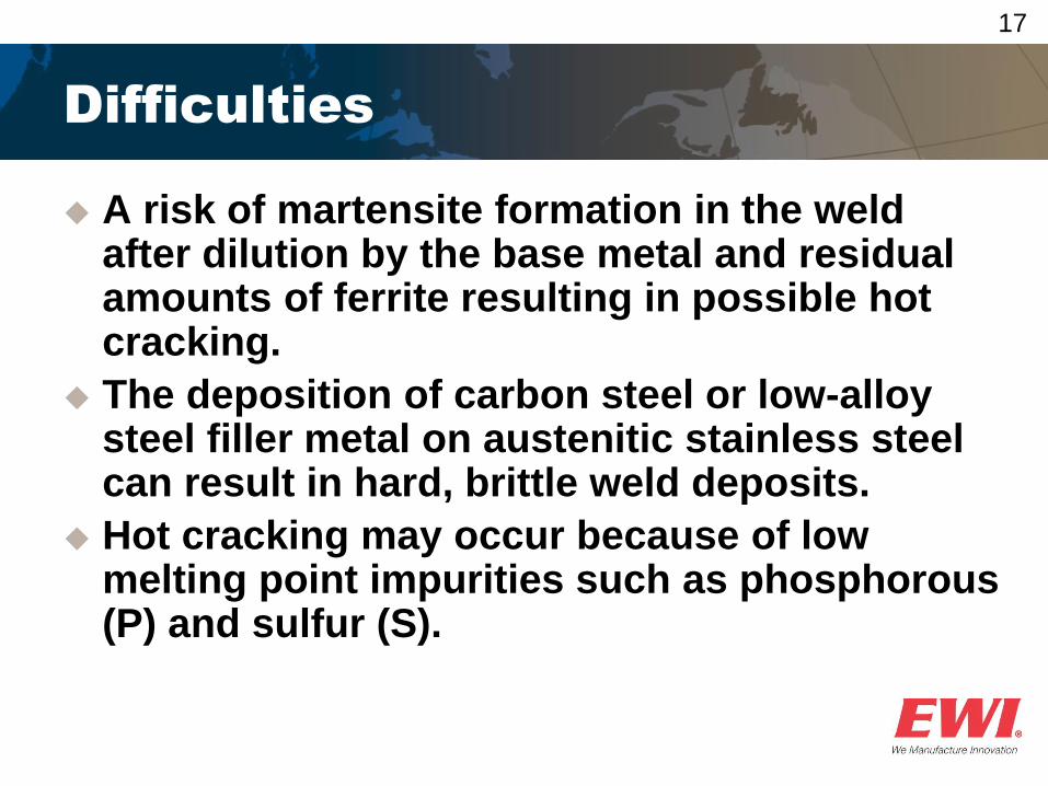
Difficulties
A risk of martensite formation in the weld after dilution by the base metal and residual amounts of ferrite resulting in possible hot cracking.
The deposition of carbon steel or low-alloy steel filler metal on austenitic stainless steel can result in hard, brittle weld deposits.
Hot cracking may occur because of low melting point impurities such as phosphorous (P) and sulfur (S).
18
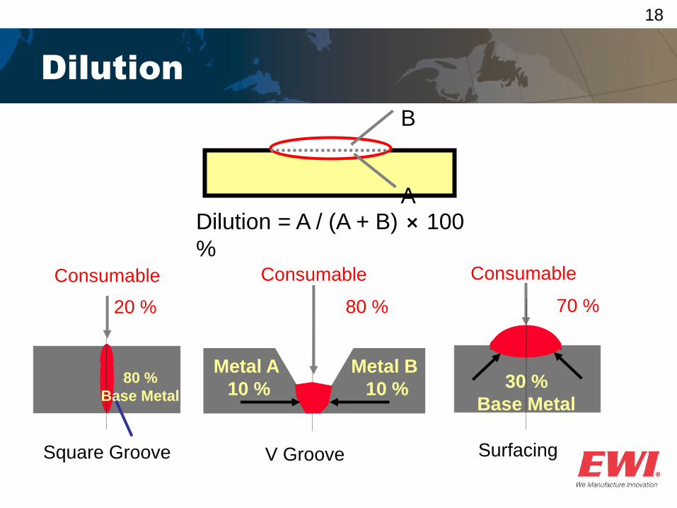
Dilution
B
A Dilution = A / (A + B) ⨯ 100
%
Square Groove
Consumable
70 %
30 %
Base Metal
80 %
Metal A
10 %
Consumable
Metal B
10 %
Consumable
20 %
80 %
Base Metal
V Groove Surfacing
19
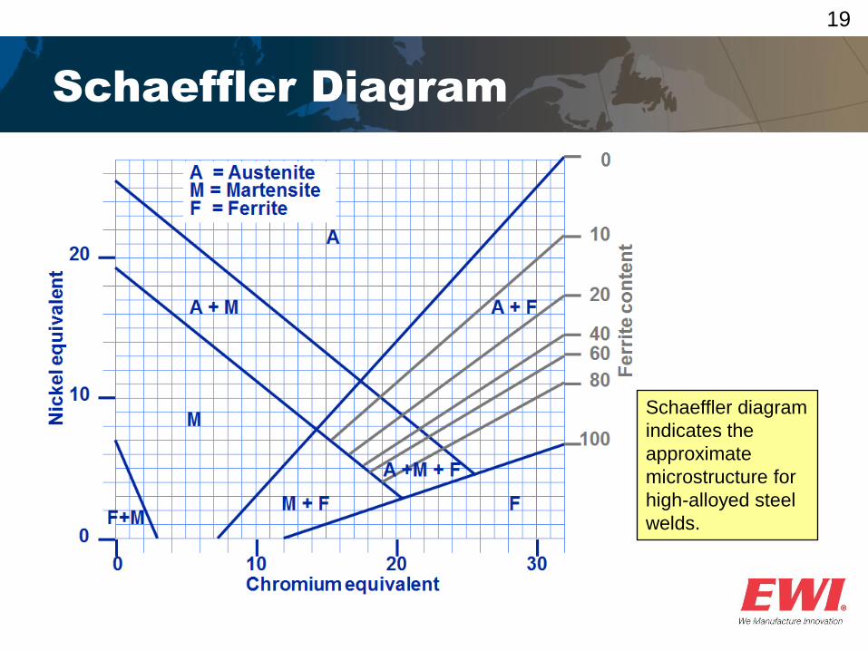
Schaeffler Diagram
Schaeffler diagram
indicates the
approximate
microstructure for
high-alloyed steel
welds.
20
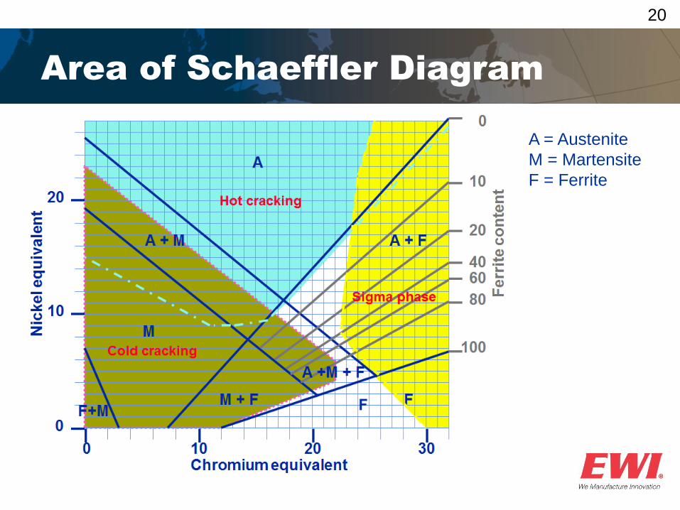
Area of Schaeffler Diagram
A = Austenite
M = Martensite
F = Ferrite
21
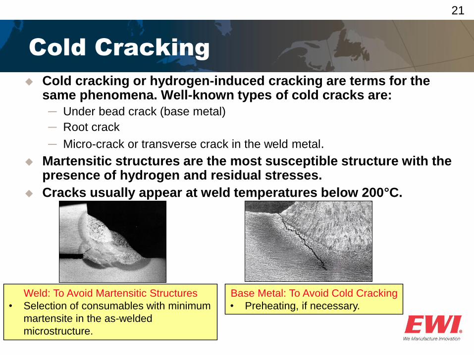
Cold Cracking
Cold cracking or hydrogen-induced cracking are terms for the same phenomena. Well-known types of cold cracks are:
─ Under bead crack (base metal)
─ Root crack
─ Micro-crack or transverse crack in the weld metal.
Martensitic structures are the most susceptible structure with the presence of hydrogen and residual stresses.
Cracks usually appear at weld temperatures below 200°C.
Weld: To Avoid Martensitic Structures
• Selection of consumables with minimum
martensite in the as-welded
microstructure.
Base Metal: To Avoid Cold Cracking
• Preheating, if necessary.
22
Solidification Cracking
Hot cracking refers to cracking that occurs during welding, casting, or hot working at temperature close to the melting point of the material.
The cracking is known to occur both: ─ above the liquation temperature known as super-solidus
cracking and
─ in solid state, called sub-solidus cracking.
Super-solidus cracking may manifest as: ─ Solidification cracking occurs in the presence of a liquid phase in
the fusion zone, or as
─ Liquation cracking in the heat-affected zone where it is accompanied by grain boundary melting.
To Avoid Low Melting Constituents:
• Selection of consumables with at least 5 vol.-% ferrite
in the as-welded microstructure.
23
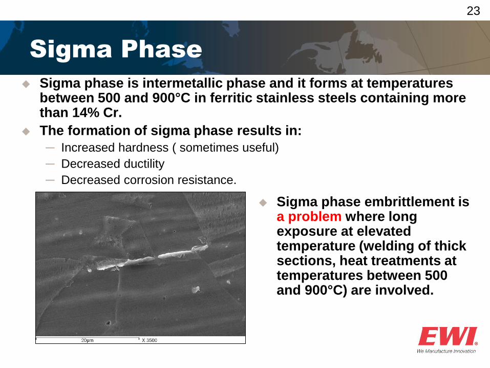
Sigma Phase
Sigma phase embrittlement is a problem where long exposure at elevated temperature (welding of thick sections, heat treatments at temperatures between 500 and 900°C) are involved.
Sigma phase is intermetallic phase and it forms at temperatures between 500 and 900°C in ferritic stainless steels containing more than 14% Cr.
The formation of sigma phase results in:
─ Increased hardness ( sometimes useful)
─ Decreased ductility
─ Decreased corrosion resistance.
24
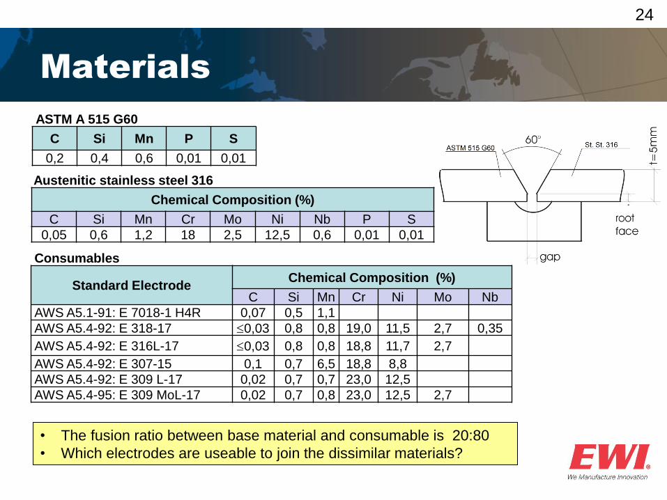
Materials
Consumables
Standard Electrode Chemical Composition (%)
C Si Mn Cr Ni Mo Nb
AWS A5.1-91: E 7018-1 H4R 0,07 0,5 1,1
AWS A5.4-92: E 318-17 0,03 0,8 0,8 19,0 11,5 2,7 0,35
AWS A5.4-92: E 316L-17 0,03 0,8 0,8 18,8 11,7 2,7
AWS A5.4-92: E 307-15 0,1 0,7 6,5 18,8 8,8
AWS A5.4-92: E 309 L-17 0,02 0,7 0,7 23,0 12,5
AWS A5.4-95: E 309 MoL-17 0,02 0,7 0,8 23,0 12,5 2,7
Austenitic stainless steel 316
Chemical Composition (%)
C Si Mn Cr Mo Ni Nb P S
0,05 0,6 1,2 18 2,5 12,5 0,6 0,01 0,01
ASTM A 515 G60
C Si Mn P S
0,2 0,4 0,6 0,01 0,01
• The fusion ratio between base material and consumable is 20:80
• Which electrodes are useable to join the dissimilar materials?
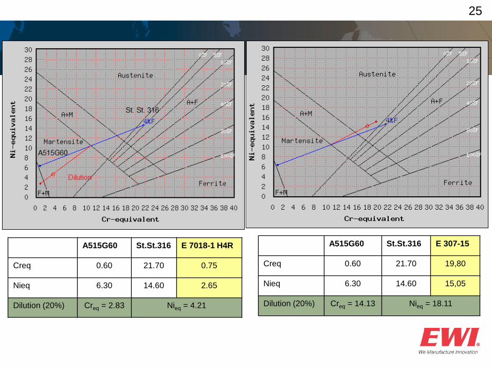
25
A515G60 St.St.316 E 7018-1 H4R
Creq 0.60 21.70 0.75
Nieq 6.30 14.60 2.65
Dilution (20%) Creq = 2.83 Nieq = 4.21
A515G60 St.St.316 E 307-15
Creq 0.60 21.70 19,80
Nieq 6.30 14.60 15,05
Dilution (20%) Creq = 14.13 Nieq = 18.11
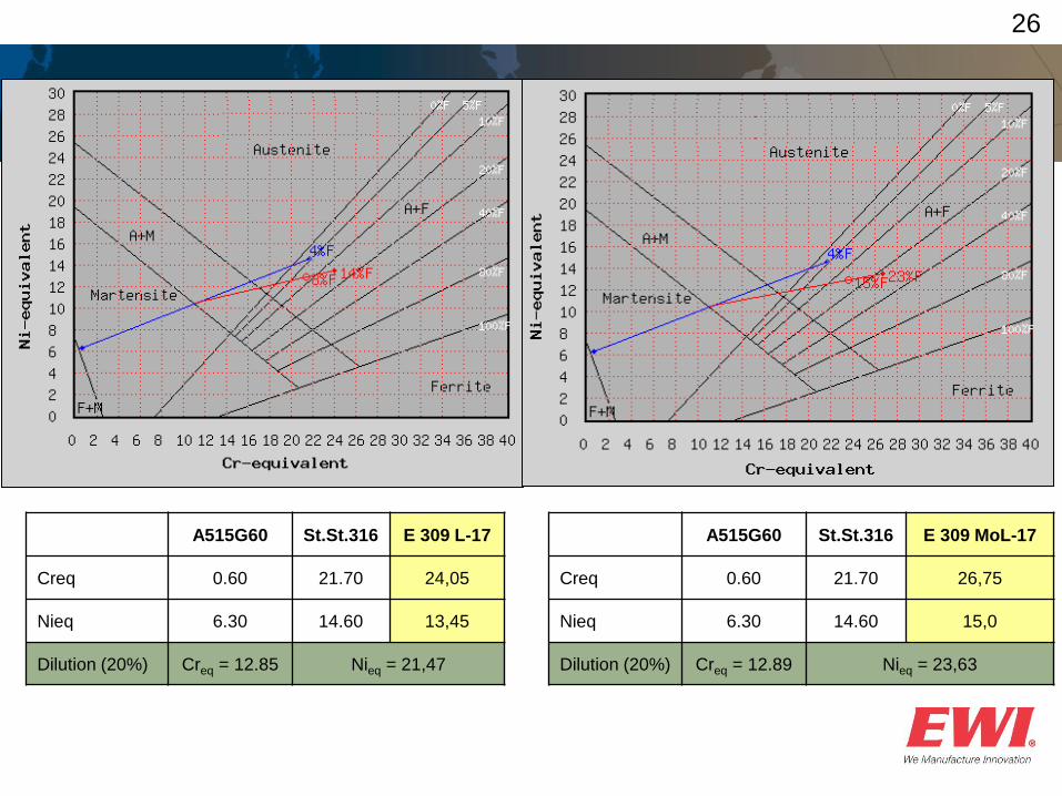
26
A515G60 St.St.316 E 309 L-17
Creq 0.60 21.70 24,05
Nieq 6.30 14.60 13,45
Dilution (20%) Creq = 12.85 Nieq = 21,47
A515G60 St.St.316 E 309 MoL-17
Creq 0.60 21.70 26,75
Nieq 6.30 14.60 15,0
Dilution (20%) Creq = 12.89 Nieq = 23,63
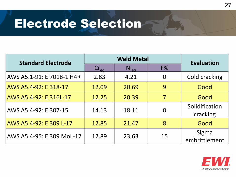
27
Electrode Selection
Standard Electrode Weld Metal
Evaluation Creq Nieq F%
AWS A5.1-91: E 7018-1 H4R 2.83 4.21 0 Cold cracking
AWS A5.4-92: E 318-17 12.09 20.69 9 Good
AWS A5.4-92: E 316L-17 12.25 20.39 7 Good
AWS A5.4-92: E 307-15 14.13 18.11 0 Solidification
cracking
AWS A5.4-92: E 309 L-17 12.85 21,47 8 Good
AWS A5.4-95: E 309 MoL-17 12.89 23,63 15 Sigma
embrittlement

Questions?
Case Studies
Dissimilar Joining of Steel to Aluminum
30
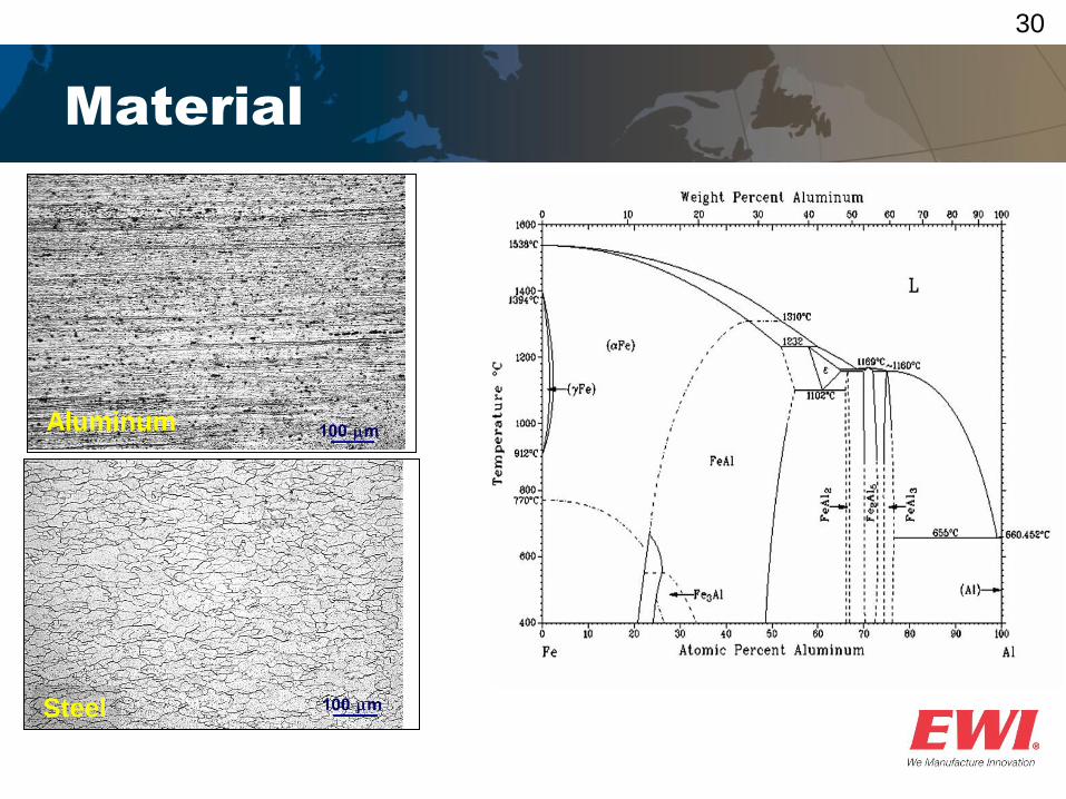
Material
Aluminum
Steel
31
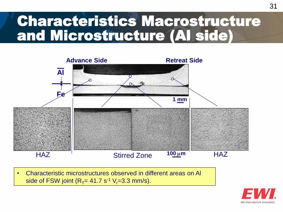
Characteristics Macrostructure
and Microstructure (Al side)
O O
O O
Al
Fe 1 mm
HAZ HAZ 100 m
• Characteristic microstructures observed in different areas on Al
side of FSW joint (RT= 41.7 s-1 Vr=3.3 mm/s).
Stirred Zone
Retreat Side Advance Side
32
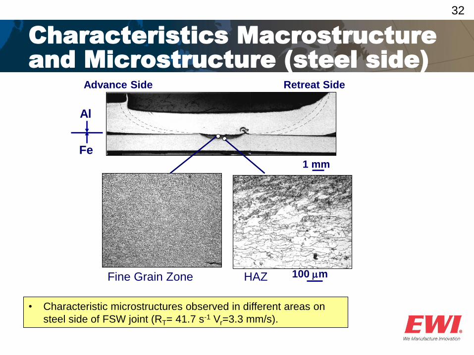
Characteristics Macrostructure
and Microstructure (steel side)
1 mm
100 m HAZ
Al
Fe
• Characteristic microstructures observed in different areas on
steel side of FSW joint (RT= 41.7 s-1 Vr=3.3 mm/s).
Fine Grain Zone
Retreat Side Advance Side
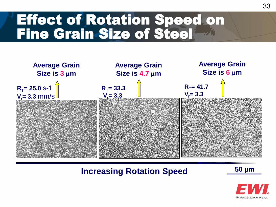
33
Effect of Rotation Speed on
Fine Grain Size of Steel
Increasing Rotation Speed 50 µm
RT= 25.0 s-1
Vr= 3.3 mm/s
RT= 33.3
Vr= 3.3
RT= 41.7
Vr= 3.3
Average Grain
Size is 3 m
Average Grain
Size is 4.7 m
Average Grain
Size is 6 m
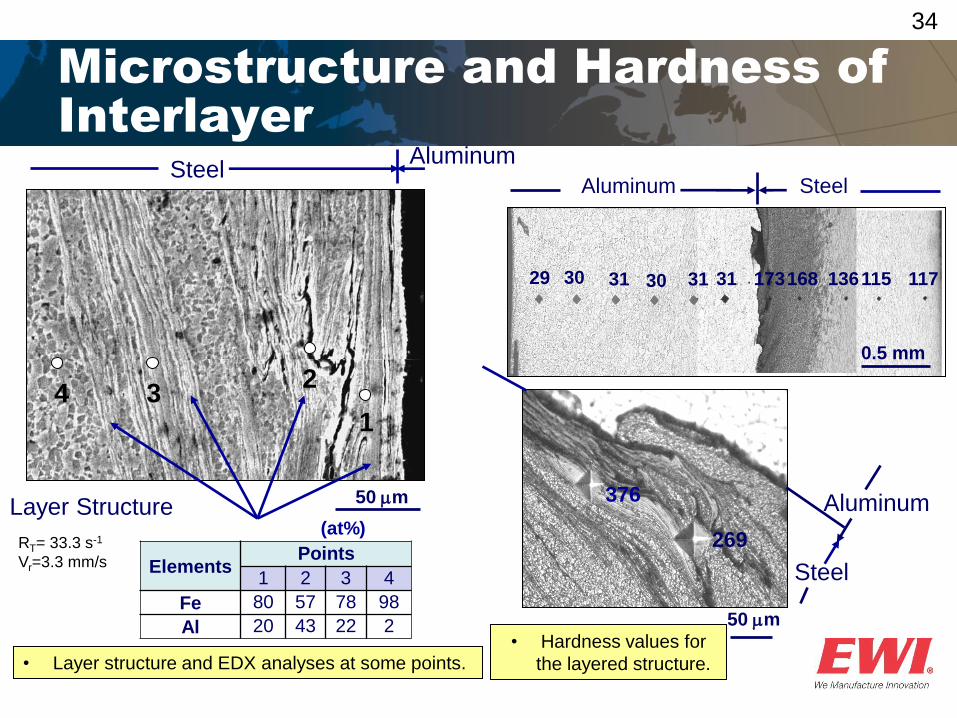
34
Microstructure and Hardness of
Interlayer
• Layer structure and EDX analyses at some points.
Elements Points
1 2 3 4
Fe 80 57 78 98
Al 20 43 22 2
(at%)
Aluminum Steel
50 m
1
2 3 4
Layer Structure
RT= 33.3 s-1
Vr=3.3 mm/s
Aluminum
Steel
50 m
269
376
Aluminum Steel
29 30 31 30 31 31 173 168 136 115 117
0.5 mm
• Hardness values for
the layered structure.
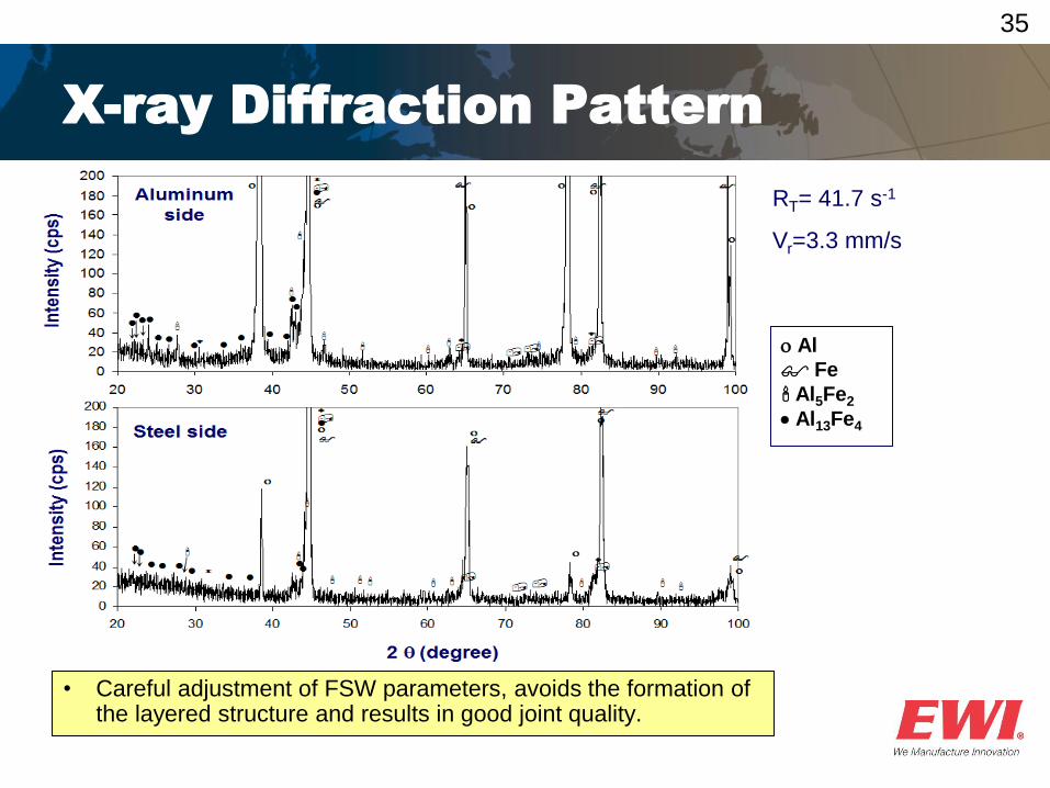
35
Al
Fe
Al5Fe2
Al13Fe4
RT= 41.7 s-1
Vr=3.3 mm/s
X-ray Diffraction Pattern
• Careful adjustment of FSW parameters, avoids the formation of the layered structure and results in good joint quality.
Questions?

Case Studies
Dissimilar Welding of Nodular Cast Iron to Steel
38
Problems
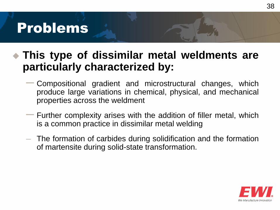
This type of dissimilar metal weldments are particularly characterized by:
─ Compositional gradient and microstructural changes, which produce large variations in chemical, physical, and mechanical properties across the weldment
─ Further complexity arises with the addition of filler metal, which is a common practice in dissimilar metal welding
─ The formation of carbides during solidification and the formation of martensite during solid-state transformation.
39
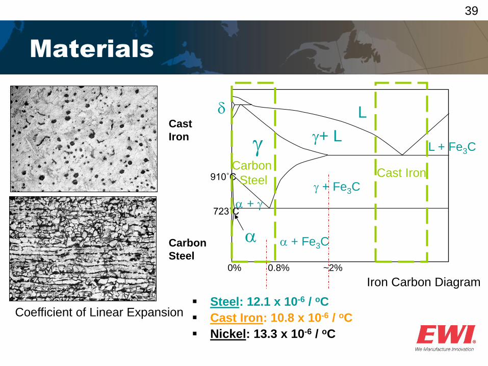
Materials
Iron Carbon Diagram
L
a + Fe3C
d
+ L
a +
L + Fe3C
723˚C
910˚C
0% 0.8% ~2%
a
+ Fe3C Cast Iron
Carbon
Steel
Coefficient of Linear Expansion Steel: 12.1 x 10⁻⁶ / oC
Cast Iron: 10.8 x 10⁻⁶ / oC
Nickel: 13.3 x 10⁻⁶ / oC
Carbon
Steel
Cast
Iron
40
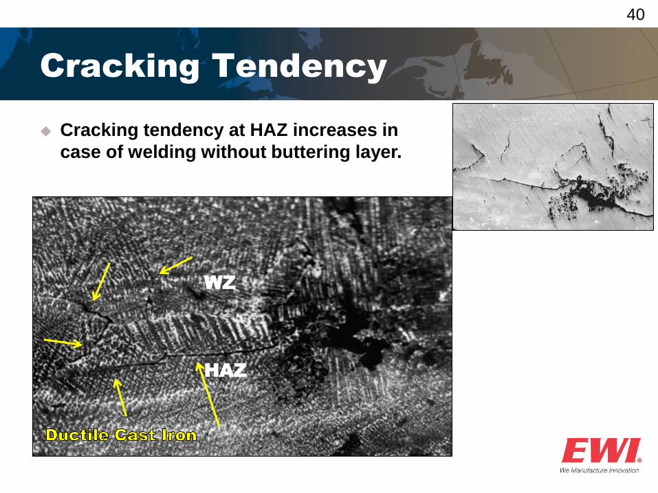
Cracking Tendency
Cracking tendency at HAZ increases in
case of welding without buttering layer.
WZ
HAZ
41
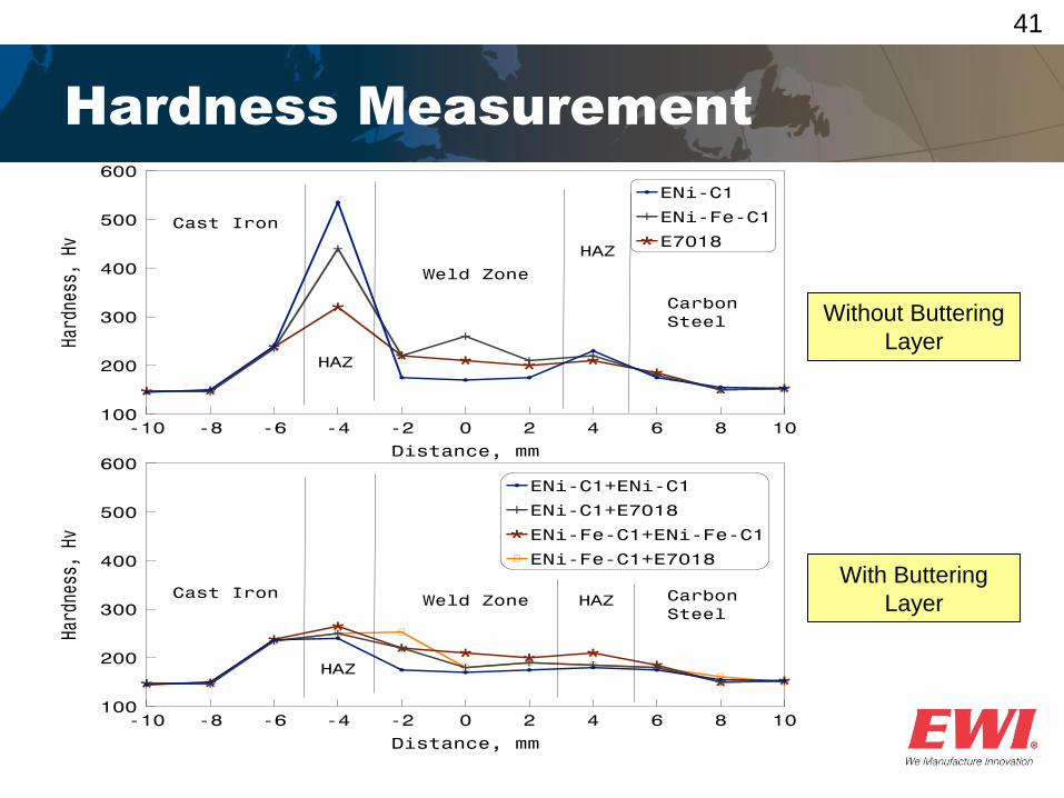
Hardness Measurement
Without Buttering
Layer
With Buttering
Layer
42
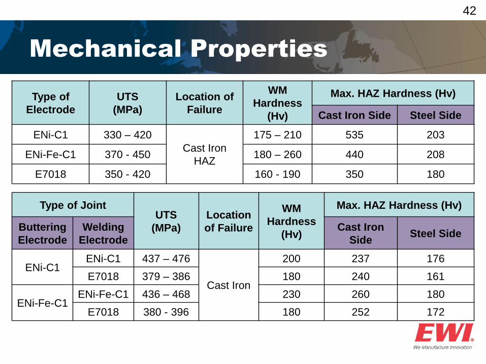
Mechanical Properties
Type of
Electrode
UTS
(MPa)
Location of
Failure
WM
Hardness
(Hv)
Max. HAZ Hardness (Hv)
Cast Iron Side Steel Side
ENi-C1 330 – 420
Cast Iron
HAZ
175 – 210 535 203
ENi-Fe-C1 370 - 450 180 – 260 440 208
E7018 350 - 420 160 - 190 350 180
Type of Joint UTS
(MPa)
Location
of Failure
WM
Hardness
(Hv)
Max. HAZ Hardness (Hv)
Buttering
Electrode
Welding
Electrode
Cast Iron
Side Steel Side
ENi-C1 ENi-C1 437 – 476
Cast Iron
200 237 176
E7018 379 – 386 180 240 161
ENi-Fe-C1 ENi-Fe-C1 436 – 468 230 260 180
E7018 380 - 396 180 252 172
43
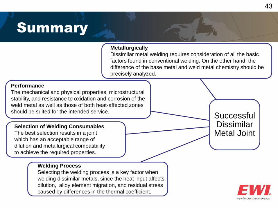
Summary
Successful Dissimilar Metal Joint
Metallurgically
Dissimilar metal welding requires consideration of all the basic
factors found in conventional welding. On the other hand, the
difference of the base metal and weld metal chemistry should be
precisely analyzed.
Performance
The mechanical and physical properties, microstructural
stability, and resistance to oxidation and corrosion of the
weld metal as well as those of both heat-affected zones
should be suited for the intended service.
Selection of Welding Consumables
The best selection results in a joint
which has an acceptable range of
dilution and metallurgical compatibility
to achieve the required properties.
Welding Process
Selecting the welding process is a key factor when
welding dissimilar metals, since the heat input affects
dilution, alloy element migration, and residual stress
caused by differences in the thermal coefficient.
44
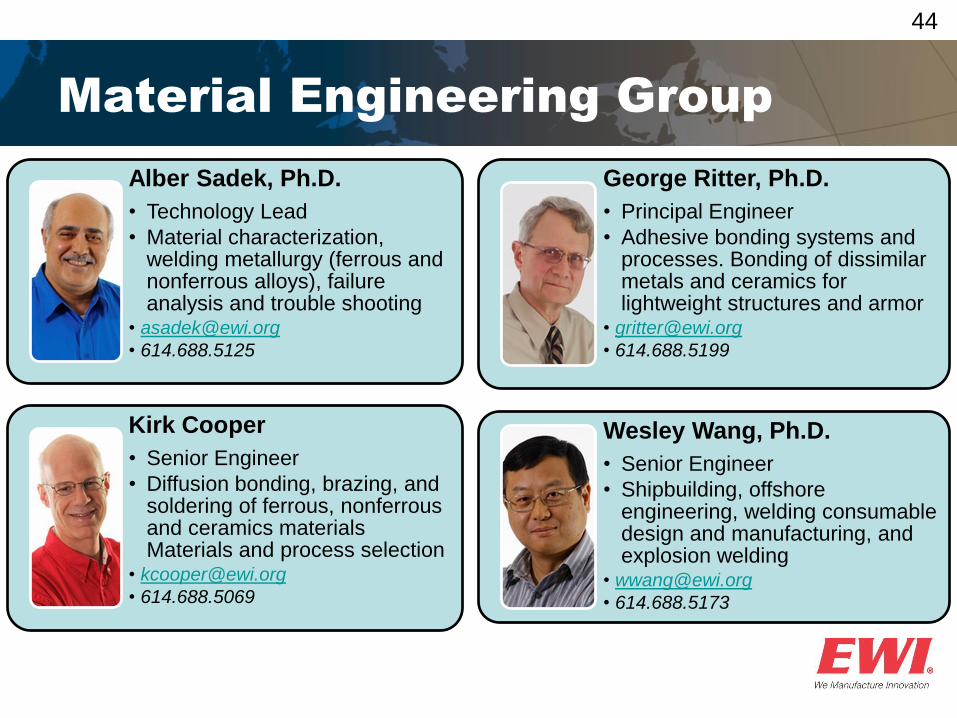
Material Engineering Group
Alber Sadek, Ph.D.
• Technology Lead
• Material characterization, welding metallurgy (ferrous and nonferrous alloys), failure analysis and trouble shooting
• 614.688.5125
Kirk Cooper
• Senior Engineer
• Diffusion bonding, brazing, and soldering of ferrous, nonferrous and ceramics materials Materials and process selection
• 614.688.5069
George Ritter, Ph.D.
• Principal Engineer
• Adhesive bonding systems and processes. Bonding of dissimilar metals and ceramics for lightweight structures and armor
• 614.688.5199
Wesley Wang, Ph.D.
• Senior Engineer
• Shipbuilding, offshore engineering, welding consumable design and manufacturing, and explosion welding
• 614.688.5173

Questions?
Thank you!
If you would like to learn more or continue this discussion with Alber, members can reach out to Alber as part of their Member Services. If you are not a member of EWI, please visit our website at www.ewi.org to learn more about membership.
47
EWI is the leading engineering and technology organization in North America dedicated to developing, testing, and implementing
advanced manufacturing technologies for industry. Since 1984, EWI has offered applied research, manufacturing support, and
strategic services to leaders in the aerospace, automotive, consumer electronic, medical, energy, government and defense, and
heavy manufacturing sectors. By matching our expertise to the needs of forward-thinking manufacturers, our technology team serves
as a valuable extension of our clients’ innovation and R&D teams to provide premium, game-changing solutions that deliver a
competitive advantage in the global marketplace.
LOCATIONS
Columbus, Ohio
(Headquarters)
1250 Arthur E. Adams Drive
Columbus, OH 43221
614.688.5000
Buffalo, New York
847 Main Street
Buffalo, NY 14203
716.710.5500
Metro DC
11921 Freedom Drive, Suite 550
Reston, VA 20190
703.665.6604