Embed Size (px)
Citation preview
MSU Solar Car Motor Controller
Michigan State UniversitySenior Design – ECE 480 – Team 9
Fall 2013 Project Sponsor:
MSU Solar
Project Facilitator:Binseng Wang
Team Members:Jaime Alvarez
Scott O’ConnorMatt Myers
Chris Sommer
1

Table of Contents 1. Background
1.1 Background………………………………………………………………………..………...……….4 1.2 Currently Available Devices……………………………………………………………………...4
1.2.1 NGM Motor Controller 1.2.2 Kelly Motor Controller1.2.3 Tritium Motor Controller
2. Technical Section 2.1 Design Specifications………………………………………………………………………..……..6
2.1.1 Function2.1.2 Performance2.1.3 Delivery Date2.1.4 Quantity2.1.5 Environmental Conditions2.1.6 Safety2.1.7 Energy Consumption2.1.8 Reliability 2.1.9 Maintenance2.1.10 Electrical Loading2.1.11 Size2.1.12 Weight2.1.13 Packaging2.1.14 Motor Controls Connectors2.1.15 Service Life2.1.16 Operating Instructions2.1.17 Initial Prototyping Cost2.1.18 Motor Controls Connectors
2.2 FAST Diagram………………………………………………………………………………….…....92.2.1 Fast Diagram
2.3 Conceptual Design Stages……………………………..…...…………………………...……..…92.3.1 Small Scale Design2.3.2 Limited Large Scale design
2.3.3 Full Scale Design2.3.4 Ranking Conceptual Designs
2.4 Proposed Design Solutions…………………………………………..…………………....…….102.4.1 More robust MOSFETs2.4.2 Increase Repairability2.4.3 Higher performing Heat sink on MOSFETs2.4.4 Include Upgradeability2.4.5 First Board Layout2.4.6 Gate Driver Integration2.4.7 DSP and Software
3. Project Management3.1 Gantt Chart…………………………………………………………..………………………....…...14
4. Cost Section4.1 Budget……………………………………………………………………...…..………………….…17
5. References
2
Executive Summary:The Solar Car Team is one of the latest racing teams to take hold at Michigan State
University. Since 2010 the team has participated in two races and has been unable to complete the race due to unreliable components. The Michigan State Solar Car Racing Team competed in the American Solar Challenge for the first time in 2012. Ten miles into the race the NGM motor controller being used on the car failed and stopped working. During the attempt to fix the motor controller it was found that the NGM controller lacked robustness to hold up to the demands of the car. The area of weakness in the controller was in the high voltage distribution section, particularly the MOSFETS which could not handle the current demand of the motor. With a new design the motor controller can be built to be more reliable and easier to repair which will prevent the car from being unable to race in its next event.
In order to build a more effective motor controller we must look into improvements in the four main sections of the motor controller which include the control inputs, the micro electronics, the control algorithm, and the high voltage controls. All of the previous problems we have had with our motor controllers have involved the high voltage controls so that is the area that we will focus on. The improvements in this system will come from MOSFETS with higher voltage and current ratings and capacitors with a higher capacitance. These high power components will be controlled by the programmed micro-electronics which will use information from control inputs to make decisions. The goal of this project is to have a motor controller that will spin the motor and hold up to peak power demands.
3

1 Technical1.1 Background: What is a motor controller?
A motor controller is an electronic component of a drive system that converts a DC voltage into a three phase AC signal that can drive an AC motor. The motor controller converts the DC to AC using a 6-step inverter which is implemented with high power MOSFETS. The motor controller also includes controls that determine the AC output of the controller. It is necessary for the AC output to be variable so that the user can change the speed of the motor. The motor uses information taken from the motor via Hall Effect sensors and the user input to determine the output. All the calculations necessary to evaluate the output are done with a Digital Signal Processor (DSP). The DSP then sends a pulse width modulation signal to the MOSFETS that switch on and off and create 3 separate sine waves. These sine waves form together to create a three phase AC signal. This AC signal is sent directly to the motor and causes it to spin.
Most modern motor controllers are also equipped with regenerative capabilities. Regeneration allows the motor controller to gain back energy that it has already put out when the driver is braking. This is especially important in electric vehicles because of the limited amount of energy in the batteries.
1.2 Currently Available Devices1.2.1 NGM Motor Controller:
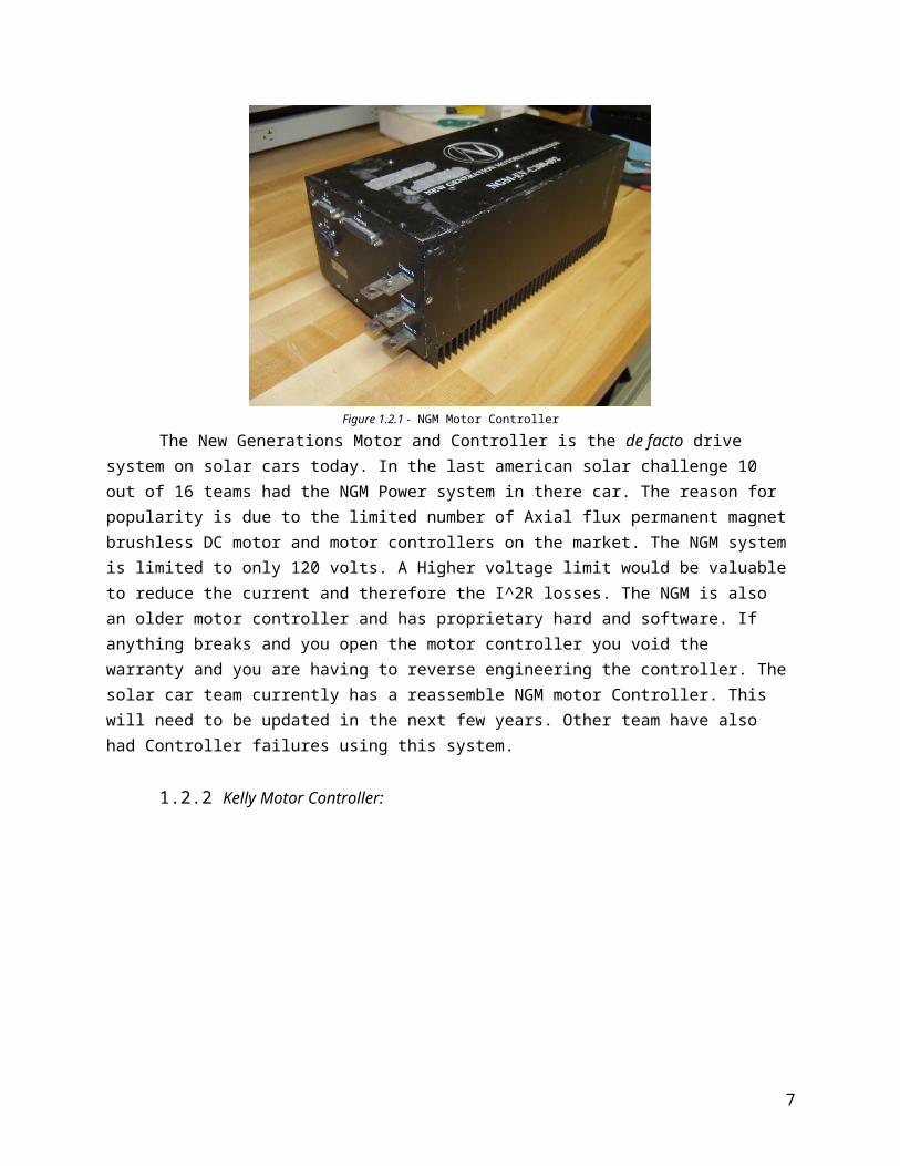
Figure 1.2.1 - NGM Motor Controller
The New Generations Motor and Controller is the de facto drive system on solar cars today. In the last american solar challenge 10 out of 16 teams had the NGM Power system in there car. The reason for popularity is due to the limited number of Axial flux permanent magnet brushless DC motor and motor controllers on the market. The NGM system is limited to only 120 volts. A Higher voltage limit would be valuable to reduce the current and therefore the I^2R losses. The NGM is also an older motor controller and has proprietary hard and software. If
4
anything breaks and you open the motor controller you void the warranty and you are having to reverse engineering the controller. The solar car team currently has a reassemble NGM motor Controller. This will need to be updated in the next few years. Other team have also had Controller failures using this system.
1.2.2 Kelly Motor Controller:
figure 1.2.2 Kelley Motor Controller
The Kelly Motor Controller is a second motor controller option. Again the voltage is only 120 volts. This motor is not strong enough to really drive the car. The team also had a controller failure using it at the race. The controller could not be easily debugged.
1.2.3 Tritium Motor Controller:
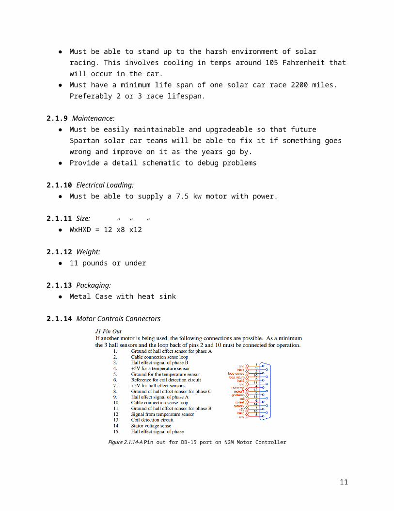
Figure 1.2.3
The Tritium Motor Controller is becoming the replacement motor for the NGM that most team upgrade to. The Tritium Motor Controller has a Continuous DC bus voltage of 165V and 170 volts peak. The max power output is 20KVA. The Controller is also CAN enabled. This controller is not open source and also cost $6000. While this is a good option it is expensive. This controller also does not come with a heat sink.
5

2.1 Design Specifications:2.1.1 Function:
● Control NGM 7.5kw motor with forward and reverse capabilities as well as regenerative abilities.
● Provide motor with power while operating at an efficiency appropriate for a solar car
2.1.2 Performance:● Drive capabilities must be at least 90 percent efficient.
2.1.3 Delivery Date:
● November 18th is the official deadline for a production motor. 2.1.4 Quantity:
● We only need one functional motor controller for the car but this single unit must be reliable and repairable.
2.1.5 Environmental conditions:
● EMC● Must be waterproof to survive the solar car environment● Must be able to survive intense vibrations seen in a car with little suspension.● High heat- (120 F)
2.1.6 Safety:
● Must have an enclosure which prevents any handlers from touching high voltage rails.● Must have fail safes which prevent stops and accelerations that are unexpected● Must have faults for overcurrent and overvoltage to protect motor and controller
internals. 2.1.7 Energy consumption:
● 90 % efficiency as to keep up with leading controllers 2.1.8 Reliability:
● Must be able to stand up to the harsh environment of solar racing. This involves cooling in temps around 105 Fahrenheit that will occur in the car.
● Must have a minimum life span of one solar car race 2200 miles. Preferably 2 or 3 race lifespan.
2.1.9 Maintenance:
● Must be easily maintainable and upgradeable so that future Spartan solar car teams will be able to fix it if something goes wrong and improve on it as the years go by.
● Provide a detail schematic to debug problems 2.1.10 Electrical Loading:
● Must be able to supply a 7.5 kw motor with power.
6
2.1.11 Size:
● WxHXD = 12”x8”x12” 2.1.12 Weight:
● 11 pounds or under 2.1.13 Packaging:
● Metal Case with heat sink
2.1.14 Motor Controls Connectors
Figure 2.1.14-A Pin out for DB-15 port on NGM Motor Controller
The current motor has a sensor cable that this current motor controller must be compatible with the pinout shown above. There are three hall effect sensors, a temperature sensor, coil detection sensor, cable connection sensor and stator voltage sensor.
Older User Interface PortThere is a second input connection, a db-25 cable. This db-25 port has two sets of
potentiometer pins that are for the throttle and brake. There are also pins for RS232, forward/reverse, enable motor controller, enable throttle and other features.
7
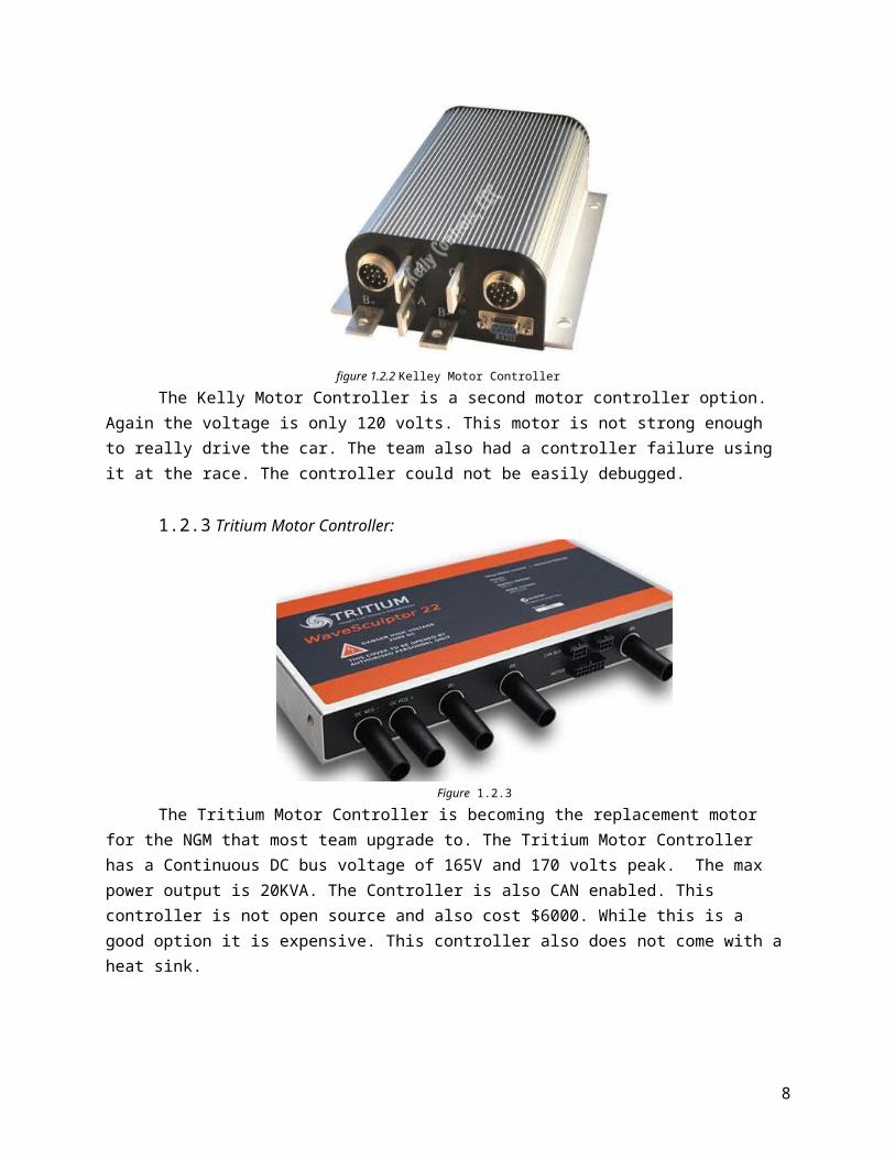
Figure 2.1.14-B DB 25 NGM Motor Controller Port
The Motor Controller has a second db-25 port that the user plugs into the car system. The necessary function that are need on the new motor controller are as follows
● Throttle input ● Regen input● Throttle enable● Enable ● Some form of serial communication● Forward/ Reverse
2.1.15 Service Life:
● Must last 2 solar car generations or 4 years with minimal upkeep by the team. 2.1.16 Operating Instructions:
● Operating should be straightforward with included manual and the motor controller should
2.1.17 Initial Prototyping Cost:
● Initial Prototyping must be under $150 2.1.18 Electrical specifications:
● Peak current output of 175 Amps● Run on a bus voltage ranging from 82 – 108 Volts● Peak Voltage of 160 Volts
8

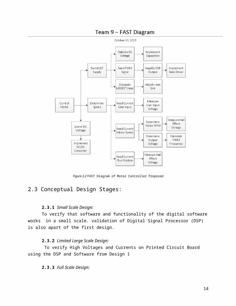
2.2 FAST Diagram: The Function Analysis System Technique (FAST) Diagram below is a way to show all of
the functions that the motor controller system will implement. This diagram moves from left to right dealing with the main function first and transitioning to the primary function and finally the numerous secondary functions following the primary. The main function of this system is to control the motor. The next column are the different primary functions that are needed for the primary function to work. The next subsequent columns are secondary functions that describe how the primary or secondary functions will be achieved. This FAST diagram is an easy way to visualize the basic functions of the system and how they rely on one another.
Figure 2.2 FAST Diagram of Motor Controller Proposed
2.3 Conceptual Design Stages:
2.3.1 Small Scale Design:To verify that software and functionality of the digital software works in a small scale.
validation of Digital Signal Processor (DSP) is also apart of the first design.
9

2.3.2 Limited Large Scale Design: To verify High Voltages and Currents on Printed Circuit Board using the DSP and
Software from Design 1
2.3.3 Full Scale Design:To verify overall design using Like Production PCBs with same DSP and Software from
Design
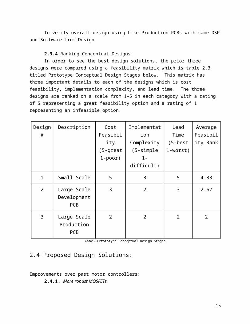
2.3.4 Ranking Conceptual Designs:In order to see the best design solutions, the prior three designs were compared using a
feasibility matrix which is table 2.3 titled Prototype Conceptual Design Stages below. This matrix has three important details to each of the designs which is cost feasibility, implementation complexity, and lead time. The three designs are ranked on a scale from 1-5 in each category with a rating of 5 representing a great feasibility option and a rating of 1 representing an infeasible option.
Design # Description Cost Feasibility(5-great 1-
poor)
Implementation Complexity(5-simple 1-
difficult)
Lead Time(5-best 1-
worst)
Average Feasibility
Rank
1 Small Scale 5 3 5 4.33
2 Large Scale Development PCB
3 2 3 2.67
3 Large Scale Production PCB
2 2 2 2
Table 2.3 Prototype Conceptual Design Stages
2.4 Proposed Design Solutions:
Improvements over past motor controllers:2.4.1. More robust MOSFETs
The mosfets in the NGM motor controller discussed above had a maximum voltage rating of 200 volts which does not leave enough head room for the voltage spikes that can occur when the car must accelerate or brake quickly. By switching to a more modern power mosfet we can attain a peak voltage of 650 volts while keeping the peak current the same. One goal with this solution is to keep the on resistance of the mosfets around 80 milliohms per phase in order to maintain efficiency in the power distribution system.
2.4.2. Increase Repairability
10
The NGM motor controller that the MSU solar car team currently uses contains four different boards that combine to control the mosfets in the controller. Our goal is to combine the separate gate driver and micro-controller boards into a single board which will be much easier to replace if it should fail. The team also will increase repairability by making this project open source and keeping all of our development information on the web. This data will help future teams by allowing them to replace parts and alter code easily.
2.4.3. Higher performing Heat sink on MOSFETs Major cause of Motor controller failures is insufficient heat dissipation. We hope
to improve upon other designs by using a bonded heat sink as opposed to an extruded aluminum heatsink. A bonded heatsink allows for longer fins in a closer proximity than an extruded version of the same size. The extruded type would be limited to an inch by the manufacturing processes while the bonded heatsink would allow us up to four inches.
2.4.4. Include UpgradeabilityUpgradeability will be important as the solar racing team at Michigan State
university grows. The ability to adapt the motor controller to different battery pack voltages as well as different motors is important to consider in design.
We plan to accomplish this by adding higher voltage capacitors that are necessary for our current pack and motor specifications. By increasing the values from 200 volts to 250 volts we allow for the capability to handle more power in the future. There is only a $10 price difference between the 200 and 250V capacitors so this feature comes at a small cost to the team. Keeping this an open source project as discussed above also improves the upgradeability of our motor controller.
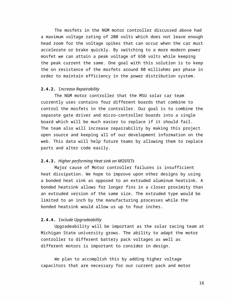
2.4.5 Preliminary Board LayoutThis is explaining the preliminary board layout using Eagle, figure 2.4.5 below.
This gives a bird’s eye view of the board layout showing all of the distances between each MOSFET pin, the square boxes, and leads for the gate drivers, the circles. This is a spot on measurement drawing for the exact board layout. Therefore this will be used as a template for mounting the MOSFETs on the heat sink. The figure below shows the large traces side to side, the blue rectangles, for the three phases A, B, and C. The red rectangles that run up and down are the traces for the positive and negative bus bars.
11
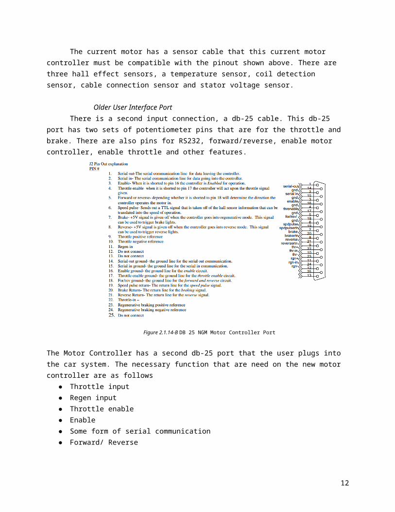
Figure 2.4.5 First Board Layout
2.4.6 Gate Driver Integration A 3 phase H-bridge inverter gate driver is desirable to simplify the design.
The high power mosfets tend to have large gate capacitance. In order to turn on mosfets at high speeds a gate driver is needed. The amount of current that can be supplied to a gate driver determines how fast the gates turn on. Gate turn on time needs to be fast enough to turn on but addition speed cause large voltage transients that decrease power efficiency. Over specing the current that the gate driver can output is desirable. It is easier to add a resistor to limit the current to the gate than updating the gate driver.
2.4.7 DSP and SoftwareThe DSP and microcontroller are the brains of the motor controller. These
devices take input from the user and the motor and compute the output necessary to drive the motor. For our design we have decided to use the Texas Instruments C2000 Luanchpad. This device comes with the Piccolo F28027 MCU and all the components needed to program it such as the JTAG and isolation. The team chose this board because it contains two 32-bit co-processors running at 50 MHZ which will be more than fast enough for our motor control application. Another aspect of this board is the software and support provided by TI. There are already several pre-written libraries and example code available on their website which will help us get our motor up and running faster. This feature will help us focus on other aspects of the controller rather than coding for most of the project. The USB port on this micro-controller also provides us with a simple way of programming the motor control. This USB input will help make it easier for future users to adapt the motor controller to a different motor or battery pack
12

voltage. The F28027 chip also contains all the ADC’s that we will need to take input from the outside environment this will makes connections to the motor simple and user friendly.
3 Project Management Plan
Name Non-Technical Role
Scott O’Connor Project Manager
Jaime Alvarez Document Presentation
Matt Myers Web Design
Chris Sommer Lab Coordinator
Table 3.1
Name Technical Role
Scott O’Connor Low Voltage Circuit and Connection design
Jaime Alvarez Sensors
Matt Myers Programming and Control Theory
Chris Sommer High Voltage Power Distribution
Table 3.2
One of the things that are needed to have a successful group is to give each person a position both technical and a non-technical role. The non-technical roles, table 3.1, are needed in order to get the project to be managed correctly. With having roles on the document preparations, website updates, and lab/part coordinator, this gives a good distribution of the certain tasks that need to be done to keep the project running smoothly. The different technical roles,table 3.2, that are assigned give each person a way to test their individual skills in order to accomplish their certain goal. Each individual part that each person make is dependent on the others finishing their part. 3 Gantt Chart:
This Gantt chart is a way for the group to stay organized and have an overview of the different tasks needed to complete this project in the time allotted. Naming the individual tasks, giving each one a deadline, and putting it under different categories will keep us organized. The Gantt chart will allow us to be able to see what tasks need to be done and monitor the progress
13
in a visual way. The Gantt chart will start from the research aspect of the project to the finalized product which will be displayed on design day.
Task Name Duration Start Finish
Research Design 13 days Wed 9/4/13 Fri 9/20/13
Research Design 11 days Wed 9/4/13 Wed 9/18/13
Research MOSFETs 13 days Wed 9/4/13 Fri 9/20/13
Research Gate Drivers 13 days Wed 9/4/13 Fri 9/20/13
Research DSP 13 days Wed 9/4/13 Fri 9/20/13
Control Algorithms 13 days Wed 9/4/13 Fri 9/20/13
Order Parts 14 days Fri 9/20/13 Wed 10/9/13
DSP 6 days Sun 9/22/13 Fri 9/27/13
MOSFETs 2 days Fri 9/27/13 Mon 9/30/13
Heat Sink 5 days Tue 10/1/13 Mon 10/7/13
Gate Drivers 3 days Mon 10/7/13 Wed 10/9/13
Prototype 1 16 days Thu 10/10/13 Thu 10/31/13
DSP 11 days Thu 10/10/13 Thu 10/24/13
Programing DSP - Waveform 7 days Thu 10/10/13 Fri 10/18/13
O-Scope Validation of outputs 2 days Mon 10/21/13 Tue 10/22/13
Connector for PWM output 3 days Tue 10/22/13 Thu 10/24/13
Find DC-DC Converter 5 days Fri 10/18/13 Thu 10/24/13
Gate Drivers 6 days Fri 10/11/13 Fri 10/18/13
Prototype PCB for gate Drivers 3 days Fri 10/11/13 Tue 10/15/13
Test Gate Driver on Load 4 days Tue 10/15/13 Fri 10/18/13
Mosfet-Power Hardware 11 days Fri 10/11/13 Fri 10/25/13
Design PCB 6 days Fri 10/11/13 Fri 10/18/13
Draw Power Out Component in CAD 7 days Fri 10/11/13 Sun 10/20/13
14
Fabricate PCB 3 days Mon 10/21/13 Wed 10/23/13
Assemble PCB 4 days Tue 10/22/13 Fri 10/25/13
Mounting Heat Sinks 5 days Mon 10/21/13 Fri 10/25/13
Connection 3 days Wed 10/23/13
Fri 10/25/13
Connectors 16 days Thu 10/10/13 Thu 10/31/13
5 to 3.3 optoisolator (order) 1 day Thu 10/10/13 Thu 10/10/13
Turn on transistors using Gate Driver (Function Generator)
2 days Fri 10/25/13 Mon 10/28/13
Test 3 Phase control with arduino 2 days Mon 10/28/13 Tue 10/29/13
Connect DSP and Gate Driver with transistors 3 days Tue 10/29/13 Thu 10/31/13
Connect Hall sensor dummy () 3 days Tue 10/29/13 Thu 10/31/13
Full Motor Test low power 1 day Thu 10/31/13 Thu 10/31/13
Prototype 2 11 days Fri 11/1/13 Fri 11/15/13
Heat Sink Template 3 days Fri 11/1/13 Tue 11/5/13
Machine Shop Holes 3 days Wed 11/6/13 Fri 11/8/13
Full Scale Prototype 6 days Fri 11/1/13 Fri 11/8/13
Full Motor Test High Power 6 days Fri 11/8/13 Fri 11/15/13
Final Testing 10 days Mon 11/18/13
Sat 11/30/13
Additional Motor Specs 11 days Mon 11/18/13 Sat 11/30/13
Due Dates 68 days Wed 9/4/13 Fri 12/6/13
PreProposal 6 days Fri 9/13/13 Fri 9/20/13
PreProposal Presentation 6 days Mon 10/7/13 Mon 10/14/13
Design Issues Paper 5 days Mon 10/14/13 Fri 10/18/13
Engineering Notebook 2 days Fri 10/18/13 Mon 10/21/13
15
Application Note 6 days Mon 10/28/13 Mon 11/4/13
Team Design Issues Paper 11 days Fri 11/8/13 Fri 11/22/13
Professional Self-Assessment Paper 4 days Fri 11/22/13 Wed 11/27/13
Final Report 6 days Wed 11/27/13
Wed 12/4/13
Design Day 1 day Fri 12/6/13 Fri 12/6/13
Table 3.1 Gantt Chart
16
4. BudgetEstimated Project Cost:
The team had to carefully choose each individual component to make sure it was within a reasonable price range. The budget that we had to adhere to was $500. With this budget we had to search for other ways to receive these different components in order to not go over the budget.
Table 4.1 Budget
Sponsorship: Our team was generously sponsored with free parts from the three different companies above including STmicroelectronics, Saturn Electronics, and Texas instruments. STmicroelectronics provided us with the MOSFETS shown in table 4.1 while Texas instruments sent us free samples of gate drivers that the team used for testing and prototyping. Saturn electronics has agreed to manufacture all the PCB’s that will be used in our design. All of the other parts needed for the controller were sponsored by the Michigan State University solar car team. The team is funded by donations from many other organizations that are listed on the solar car website, www.msusolar.com.
17
5 Resources4.1 http://www.ngmcorp.com/
New Generation Motor Works Website 4.2 http://tritium.com.au/
Tritium Website4.3 http://kellycontroller.com/kbl9625124-96v250abldc-controllerwith-regen-p-1123.html
Kelly Controls Website4.4 http://solarcar.stanford.edu/
Stanford Solar Website4.5 http://ww1.microchip.com/downloads/en/AppNotes/00898a.pdf
Determining MOSFET Driver Needs for Motor Drive Applications4.6 http://www.ti.com/lit/ug/spruhh2/spruhh2.pdf
C2000 Micro Controller Data Sheet4.7 http://www.ti.com/lit/sg/sprb176p/sprb176p.pdf
C2000 catalog
18

![animeo IB+ 1 AC Motor Controller WM/PCB 100-240 V AC · animeo IB+ 1 AC MOTOR CONTROLLER. REF. 5047280 - 6/12 A IMAGES [1] 1 AC Motor Controller WM 100-240 V AC, montage mural [2]](https://img.pdfslide.tips/doc/110x75/5f6960f7dc32117dba09e2a1/animeo-ib-1-ac-motor-controller-wmpcb-100-240-v-ac-animeo-ib-1-ac-motor-controller.jpg)


![animeo LON 4 DC/E Motor Controller WM/DRM 220 - 230 … A [3] [4] [4] Controller. E -–](https://img.pdfslide.tips/doc/110x75/5ac024c77f8b9ac6688bd286/animeo-lon-4-dce-motor-controller-wmdrm-220-230-a-3-4-4-controller.jpg)