Embed Size (px)
Citation preview
8/13/2019 Doebestpractice Casting
http://slidepdf.com/reader/full/doebestpractice-casting 1/116
Theoretical/Best PracticeEnergy Use In Metalcasting Operations
J. F. Schifo
J.T. Radia
KERAMIDA Environmental, Inc.Indianapolis, IN
May 2004
Prepared under Contract to
Advanced Technology Institute
North Charleston, SC
for the
U.S. Department of Energy
Industrial Technologies Program
Washington, DC
Industrial Technologies Program
Boosting the productivity and competitiveness of U.S. industry through improvements in energy
and environmental performance

8/13/2019 Doebestpractice Casting
http://slidepdf.com/reader/full/doebestpractice-casting 2/116
Errata Sheet
This is a listing of the corrections that were made since the original posting of theTheoretical/Best Practice Energy Use In Metalcasting Operations in April 2004.
Text Errors
• Cover, in the title Metal Casting was two words and changed to one word“Metalcasting”.
• Page 9, the following sentence was inserted. “This study, therefore, utilized actualmetalcasting energy usage by facility type to calculate the total energy used by alloy,rather than summaries of energy consumption data by NAICS codes.”
• Page 9, the following sentence was removed: “It is estimated that the industryconsumes 466 trillion Btu tacit energy annually.”
•
Page 10, Table 9, the total 2003 row was deleted.
• Page 52, Table 31, removed total row and re-labled header on second column to“2003 Benchmark Tacit Energy.”
• Page 52, Table 32 removed total row and re-labled second column to “2003Benchmark Tacit Energy.”
• Page 62, Table 37 was removed and tables 38 through 56 where renumberedaccordingly.
1
8/13/2019 Doebestpractice Casting
http://slidepdf.com/reader/full/doebestpractice-casting 3/116
TABLE OF CONTENTS
EXECUTIVE SUMMARY ........................................................................................................... 4
INTRODUCTION ...................................................................................................................... 6
OBJECTIVE.................................................................................................................................. 6RESEARCH METHODOLOGY..................................................................................................... 6METALCASTING INDUSTRY PROFILE....................................................................................... 8ESTIMATED ENERGY USE IN THE METALCASTING INDUSTRY.............................................. 9
CHAPTER 1. MELTING........................................................................................................... 15
SECTION 1. THEORETICAL MINIMUM.................................................................................. 15SECTION 2 – BEST PRACTICE .................................................................................................. 18
IRON CASTINGS – MELTING................................................................................................. 18Induction Furnaces ........................................................................................................... 19
Cupola Melting Furnaces.................................................................................................. 25STEEL CASTINGS – MELTING ............................................................................................... 32 ALUMINUM CASTINGS – MELTING...................................................................................... 34OTHER NONFERROUS ALLOYS – MELTING.......................................................................... 40
RECOMMENDATIONS – Cu-Mg-Zn................................................................................. 41RECOMMENDATIONS – FERROUS AND NONFERROUS ................................................ 42
SECTION 3 – MELTING ENERGY AND CO2 EMISSION REDUCTIONS................................... 43
CHAPTER 2. METALCASTING ............................................................................................... 46
SECTION 1. METALCASTING METHODS............................................................................... 46CAST IRON MOLDING PROCESSES ....................................................................................... 46STEEL MOLDING PROCESSES ............................................................................................... 47
NONFERROUS CASTING PROCESSES .................................................................................... 48SECTION 2. CASTING YIELD AND SCRAP ............................................................................. 51
CHAPTER 3. OTHER ENERGY REDUCTION OPPORTUNITIES ............................................ 55
SECTION 1 – ENERGY REDUCTION OPPORTUNITIES ........................................................... 55 ANALYSIS OF METALCASTING ENERGY REQUIREMENTS................................................... 55
Heat Treating Operation................................................................................................... 58Ladle Heating.................................................................................................................... 59Energy Conservation Programs ........................................................................................ 60Energy and CO2 Reduction Summary .............................................................................. 60
SECTION 2 – COMBINED HEAT AND POWER ANALYSIS ...................................................... 61Use of Waste Energy ......................................................................................................... 62Evaluation Methodology .................................................................................................. 62
A Perspective on Exergy.................................................................................................... 64 PRIME MOVERS FOR COMBINED HEAT AND POWER AND ONSITE DISTRIBUTIONGENERATION ........................................................................................................................ 66WASTE HEAT RECOVERY OPPORTUNITIES......................................................................... 71 APPLICATION OF PRIME MOVERS TO POWER GENERATION............................................. 76 ASSESSMENT OF GENERATION POTENTIAL FOR SPECIFIC FOUNDRY OPERATIONS ........ 78
Cupola Melting Furnace ................................................................................................... 79Aluminum Stack Melter.................................................................................................... 83
2

8/13/2019 Doebestpractice Casting
http://slidepdf.com/reader/full/doebestpractice-casting 4/116
Steel Casting Heat Treating .............................................................................................. 84Ductile Iron Pipe Heat Treating........................................................................................ 85
CHP SUMMARY ..................................................................................................................... 86
GLOSSARY OF TERMS............................................................................................................ 91
REFERENCES........................................................................................................................... 94
APPENDIX “A” ....................................................................................................................... 97
APPENDIX “B” ..................................................................................................................... 105
3
8/13/2019 Doebestpractice Casting
http://slidepdf.com/reader/full/doebestpractice-casting 5/116
EXECUTIVE SUMMARY
The energy used to melt one ton of metal in a metalcasting facility is significantly higher thanthe theoretical minimum requirements. The theoretical requirements can be calculated for
melting and annealing processes. The large variety of other casting processes and value addedwork performed at some casting facilities, however, makes it difficult to calculate thetheoretical minimum requirements for the entire facility. Energy use also varies widely amongfacilities with differing sales volumes and dissimilar production castings for different end usemarket segments.
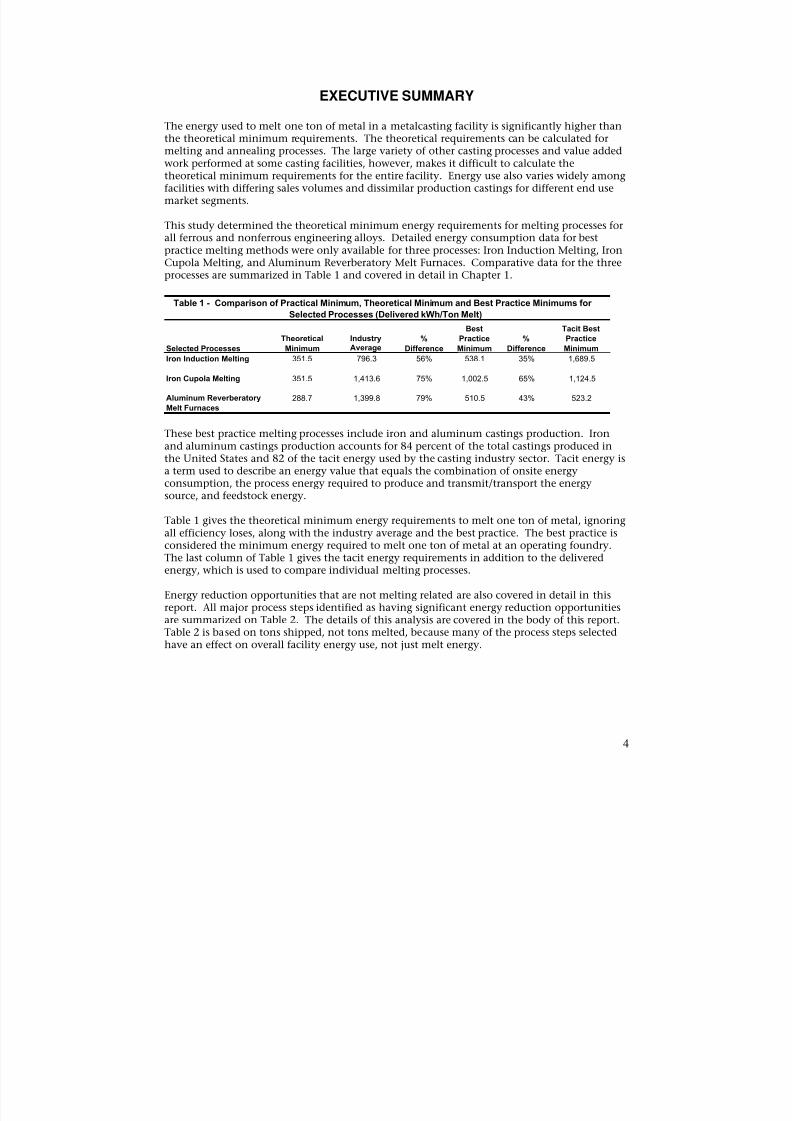
This study determined the theoretical minimum energy requirements for melting processes forall ferrous and nonferrous engineering alloys. Detailed energy consumption data for bestpractice melting methods were only available for three processes: Iron Induction Melting, IronCupola Melting, and Aluminum Reverberatory Melt Furnaces. Comparative data for the threeprocesses are summarized in Table 1 and covered in detail in Chapter 1.
Table 1 - Comparison of Practical Minimum, Theoretical Minimum and Best Practice Minimums forSelected Processes (Delivered kWh/Ton Melt)
Best Tacit Best
Selected Processes
Theoretical
Minimum
IndustryAverage
%
Difference
Practice
Minimum
%
Difference
Practice
Minimum
Iron Induction Melting 351.5 796.3 56% 538.1 35% 1,689.5
Iron Cupola Melting 351.5 1,413.6 75% 1,002.5 65% 1,124.5
Aluminum Reverberatory 288.7 1,399.8 79% 510.5 43% 523.2Melt Furnaces
These best practice melting processes include iron and aluminum castings production. Ironand aluminum castings production accounts for 84 percent of the total castings produced in
the United States and 82 of the tacit energy used by the casting industry sector. Tacit energy isa term used to describe an energy value that equals the combination of onsite energyconsumption, the process energy required to produce and transmit/transport the energysource, and feedstock energy.
Table 1 gives the theoretical minimum energy requirements to melt one ton of metal, ignoringall efficiency loses, along with the industry average and the best practice. The best practice isconsidered the minimum energy required to melt one ton of metal at an operating foundry.The last column of Table 1 gives the tacit energy requirements in addition to the deliveredenergy, which is used to compare individual melting processes.
Energy reduction opportunities that are not melting related are also covered in detail in this
report. All major process steps identified as having significant energy reduction opportunitiesare summarized on Table 2. The details of this analysis are covered in the body of this report.Table 2 is based on tons shipped, not tons melted, because many of the process steps selectedhave an effect on overall facility energy use, not just melt energy.
4
8/13/2019 Doebestpractice Casting
http://slidepdf.com/reader/full/doebestpractice-casting 6/116
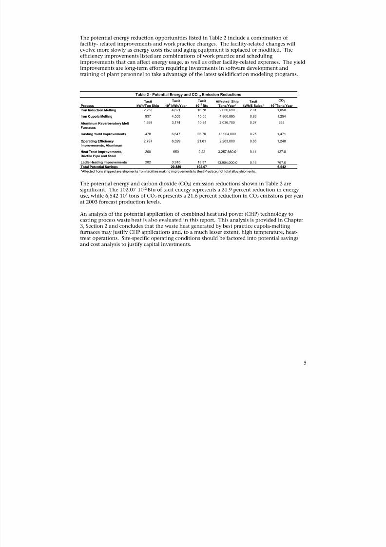
The potential energy reduction opportunities listed in Table 2 include a combination offacility- related improvements and work practice changes. The facility-related changes willevolve more slowly as energy costs rise and aging equipment is replaced or modified. Theefficiency improvements listed are combinations of work practice and schedulingimprovements that can affect energy usage, as well as other facility-related expenses. The yieldimprovements are long-term efforts requiring investments in software development and
training of plant personnel to take advantage of the latest solidification modeling programs.
Table 2 - Potential Energy and CO 2 Emission Reductions
Tacit Tacit Tacit Affected Ship Tacit CO2
Process kWh/Ton Ship 106 kWh/Year 1012 Btu Tons/Year* kWh/$ Sales* 103 Tons/Year
Iron Induction Melting 2,253 4,621 15.78 2,050,690 2.01 1,050
Iron Cupola Melting 937 4,553 15.55 4,860,895 0.83 1,254
Aluminum Reverberatory Melt 1,559 3,174 10.84 2,036,700 0.37 633
Furnaces
Casting Yield Improvements 478 6,647 22.70 13,904,000 0.25 1,471
Operating Efficiency 2,797 6,329 21.61 2,263,000 0.66 1,240
Improvements, Aluminum
Heat Treat Improvements, 200 650 2.22 3,257,660.0 0.11 127.0Ductile Pipe and Steel
Ladle Heating Improvements 282 3,915 13.37 13,904,000.0 0.15 767.0Total Potential Savings 29,889 102.07 6,542
*Affected Tons shipped are shipments from facilities making improvements to Best Practice, not total alloy shipments.
The potential energy and carbon dioxide (CO2) emission reductions shown in Table 2 aresignificant. The 102.07 1012 Btu of tacit energy represents a 21.9 percent reduction in energyuse, while 6,542 103 tons of CO2 represents a 21.6 percent reduction in CO2 emissions per yearat 2003 forecast production levels.
An analysis of the potential application of combined heat and power (CHP) technology to
casting process waste heat is also evaluated in this report. This analysis is provided in Chapter3, Section 2 and concludes that the waste heat generated by best practice cupola-meltingfurnaces may justify CHP applications and, to a much lesser extent, high temperature, heat-treat operations. Site-specific operating conditions should be factored into potential savingsand cost analysis to justify capital investments.
5
8/13/2019 Doebestpractice Casting
http://slidepdf.com/reader/full/doebestpractice-casting 7/116
INTRODUCTION
OBJECTIVEThe objective of this study is to evaluate the theoretical and practical potential for reducingenergy requirements to produce one ton of molten metal (cast iron, steel, aluminum,
magnesium, zinc and copper) and the associated carbon dioxide (CO2) emissions inmetalcasting operations.
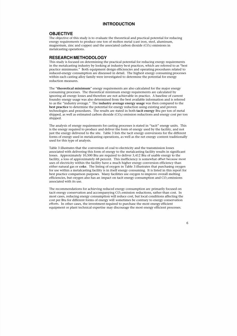
RESEARCH METHODOLOGYThis study is focused on determining the practical potential for reducing energy requirementsin the metalcasting industry by looking at industry best practices, which are referred to as “bestpractice minimums.” Both equipment design efficiencies and operating procedures related toreduced-energy consumption are discussed in detail. The highest energy consuming processeswithin each casting alloy family were investigated to determine the potential for energy
reduction measures.
The “theoretical minimum” energy requirements are also calculated for the major energyconsuming processes. The theoretical minimum energy requirements are calculated byignoring all energy losses and therefore are not achievable in practice. A baseline of currentfoundry energy usage was also determined from the best available information and is referredto as the “industry average.” The industry average energy usage was then compared to thebest practice to determine the potential for energy reduction using existing and proventechnologies and procedures. The results are stated in both tacit energy Btu per ton of metalshipped, as well as estimated carbon dioxide (CO2) emission reductions and energy cost per tonshipped.
The analysis of energy requirements for casting processes is stated in “tacit” energy units. Thisis the energy required to produce and deliver the form of energy used by the facility, and notjust the energy delivered to the site. Table 3 lists the tacit energy conversions for the different
forms of energy used in metalcasting operations, as well as the net energy content traditionallyused for this type of analysis.
Table 3 illustrates that the conversion of coal to electricity and the transmission lossesassociated with delivering this form of energy to the metalcasting facility results in significantlosses. Approximately 10,500 Btu are required to deliver 3,412 Btu of usable energy to thefacility, a loss of approximately 68 percent. This inefficiency is somewhat offset because mostuses of electricity within the facility have a much higher energy conversion efficiency thaneither natural gas or coke. The listing of oxygen in Table 3 illustrates that purchasing oxygenfor use within a metalcasting facility is in itself energy consuming. It is listed in this report forbest practice comparison purposes. Many facilities use oxygen to improve overall meltingefficiencies, but oxygen also has an impact on tacit energy consumption and CO2 emissions
associated with its use.
The recommendations for achieving reduced energy consumption are primarily focused ontacit energy conservation and accompanying CO2 emission reductions, rather than cost. Inmost cases, reducing energy consumption will reduce cost, but local conditions affecting thecost per Btu for different forms of energy will sometimes be contrary to energy conservationefforts. In other cases, the investment required to purchase the most energy efficientequipment or plant technical expertise may discourage the most energy efficient processes.
6

8/13/2019 Doebestpractice Casting
http://slidepdf.com/reader/full/doebestpractice-casting 8/116
Table 3 - Key Energy Conversion Factors
Energy Form Energy Content Tacit Energy
Coke 13,000 Btu/lb 14,000 Btu/lbElectricity 3,412 Btu/kWh 10,500 Btu/kWhNatural Gas 1,000 Btu/scf 1,026 Btu/scf
Oxygen 61 Btu/scf 175 Btu/scfMetal Casting Energy and Environamental Profile, DOE, 1999(4)
Annual Energy Outlook 2003, EIA, 2003(36)
Results of the energy analysis performed for this report are also stated in CO2 emissions. Table4 summarizes the estimated CO2 emission rates for different forms of energy.
Table 4 - CO2 Emission Factors by Energy Type
Tacit Energy
Energy Source Pounds of CO2 /106
Btu Pounds of CO2 /106
Btu
Electricity 418.74 136.19Coke 185.36 172.12
Natural Gas 117.60 114.73
Notes: CO2 emission factors from DOE 1999 Profile quoting EPA 1995 and DOE 1977 P. 44., APEC Region Options to reduce CO2 Emissions, DOE & EPA July 2000, and EPA AP-42. (4)(6)
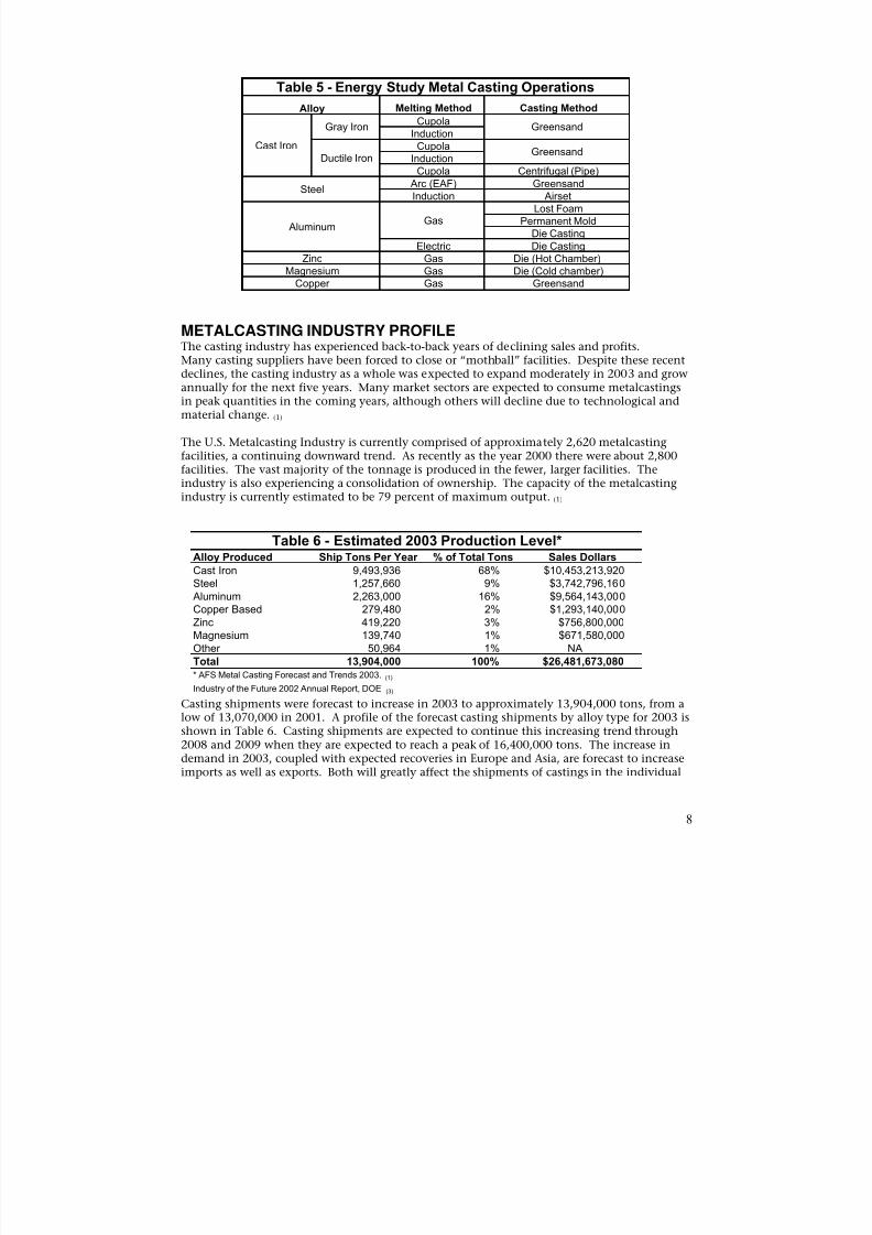
Literature searches were conducted to obtain available information on energy conservation inthe metalcasting industry. The specific processes being investigated for energy reductionpotential include those listed in Table 5. The Department of Energy (DOE) report, “Energy Usein Selected Metalcasting Facilities,”(2) (Eppich Technologies, 2003) was particularly helpful indetermining the current energy profile of the casting industry. Casting forecasts and historicalinformation were obtained from the report “2003 AFS Metalcasting Forecast & Trends”(Stratecasts, Inc., 2003)(1). Industry groups that participated in this study include the AmericanFoundry Society, Steel Founders Society of America and the North American Die Casting
Association. These organizations, industry experts, and casting equipment suppliers wereinterviewed to determine what they consider best practice. Casting facilities personnel andindustry equipment suppliers identified as best practice, were interviewed, and many werevisited to capture actual energy usage information and so that operating personnel could beinterviewed. Technical contributions were also provided by Technikon, LLC of Sacramento,California and Eppich Technologies of Parma, Ohio. The combined heat and power (CHP)analysis was provided by EnVise, LLC, of Madison, Wisconsin.
Throughout this report, several comparisons are drawn between research report findings andspecific calculations performed as part of this study. Different sources of data did not alwaysuse the same bases for the theoretical energy requirements to melt a ton of metal, and thereforethe resulting energy calculations are slightly different in some comparisons. It appears this is
the result of using different theoretical energy calculations, depending on the alloys of themetals being melted. This report does not attempt to rectify these minor differences.
7
8/13/2019 Doebestpractice Casting
http://slidepdf.com/reader/full/doebestpractice-casting 9/116
Table 5 - Energy Study Metal Casting Operations
Alloy Melting Method Casting Method
Cast Iron
Gray IronCupola
GreensandInduction
Ductile IronCupola
GreensandInduction
Cupola Centrifugal (Pipe)
Steel Arc (EAF) GreensandInduction Airset
AluminumGas
Lost FoamPermanent Mold
Die CastingElectric Die Casting
Zinc Gas Die (Hot Chamber)Magnesium Gas Die (Cold chamber)
Copper Gas Greensand
METALCASTING INDUSTRY PROFILEThe casting industry has experienced back-to-back years of declining sales and profits.Many casting suppliers have been forced to close or “mothball” facilities. Despite these recentdeclines, the casting industry as a whole was expected to expand moderately in 2003 and growannually for the next five years. Many market sectors are expected to consume metalcastingsin peak quantities in the coming years, although others will decline due to technological andmaterial change. (1)
The U.S. Metalcasting Industry is currently comprised of approximately 2,620 metalcastingfacilities, a continuing downward trend. As recently as the year 2000 there were about 2,800facilities. The vast majority of the tonnage is produced in the fewer, larger facilities. Theindustry is also experiencing a consolidation of ownership. The capacity of the metalcasting
industry is currently estimated to be 79 percent of maximum output. (1)
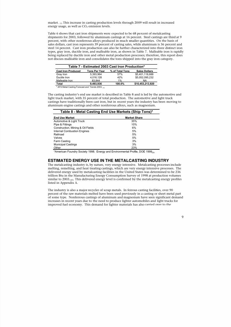
Table 6 - Estimated 2003 Production Level*Alloy Produced Ship Tons Per Year % of Total Tons Sales DollarsCast Iron 9,493,936 68% $10,453,213,920Steel 1,257,660 9% $3,742,796,160 Aluminum 2,263,000 16% $9,564,143,000Copper Based 279,480 2% $1,293,140,000Zinc 419,220 3% $756,800,000Magnesium 139,740 1% $671,580,000Other 50,964 1% NATotal 13,904,000 100% $26,481,673,080* AFS Metal Casting Forecast and Trends 2003. (1) Industry of the Future 2002 Annual Report, DOE (3)
Casting shipments were forecast to increase in 2003 to approximately 13,904,000 tons, from alow of 13,070,000 in 2001. A profile of the forecast casting shipments by alloy type for 2003 isshown in Table 6. Casting shipments are expected to continue this increasing trend through2008 and 2009 when they are expected to reach a peak of 16,400,000 tons. The increase indemand in 2003, coupled with expected recoveries in Europe and Asia, are forecast to increaseimports as well as exports. Both will greatly affect the shipments of castings in the individual
8
8/13/2019 Doebestpractice Casting
http://slidepdf.com/reader/full/doebestpractice-casting 10/116
market. (1) This increase in casting production levels through 2009 will result in increasedenergy usage, as well as CO2 emission levels.
Table 6 shows that cast iron shipments were expected to be 68 percent of metalcastingshipments for 2003, followed by aluminum castings at 16 percent. Steel castings are third at 9percent, with other nonferrous alloys produced in much smaller quantities. On the basis of
sales dollars, cast iron represents 39 percent of casting sales, while aluminum is 36 percent andsteel 14 percent. Cast iron production can also be further characterized into three distinct irontypes, gray iron, ductile iron, and malleable iron, as shown in Table 7. Malleable iron is rapidlybeing replaced by ductile iron and other metal production processes; therefore, this report doesnot discuss malleable iron and consolidates the tons shipped into the gray iron category.
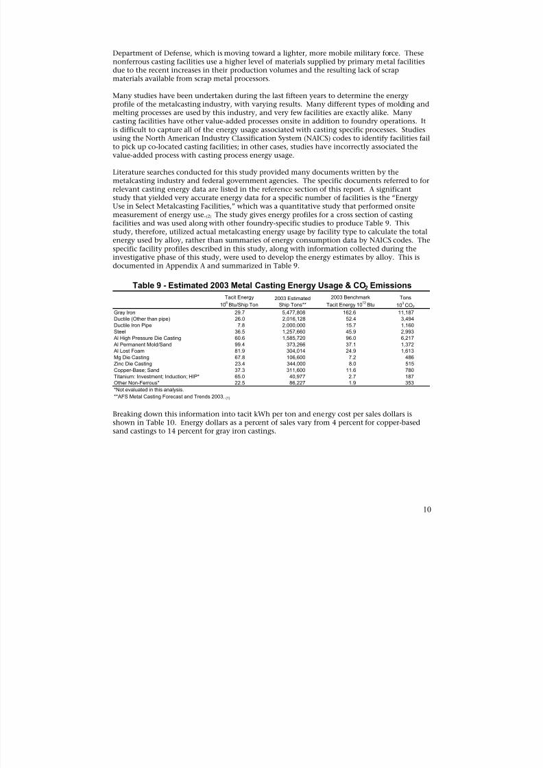
Table 7 - Estimated 2003 Cast Iron Production*Cast Iron Produced Tons Per Year % of Total Tons Sales DollarsGray Iron 5,393,964 57% $5,401,118,688Ductile Iron 4,016,128 42% $5,052,095,232Malleable Iron 83,844 1% NATotal 9,493,936 100.0% $10,453,213,920* AFS Metal Casting Forecast and Trends 2003.
(1)
The casting industry’s end use market is described in Table 8 and is led by the automotive andlight truck market, with 35 percent of total production. The automotive and light truckcastings have traditionally been cast iron, but in recent years the industry has been moving toaluminum engine castings and other nonferrous alloys, such as magnesium.
Table 8 - Metal Casting End Use Markets (Ship Tons)*
End Use Market Market Share
Automotive & Light Truck 35% Pipe & Fittings 15% Construction, Mining & Oil Fields 6% Internal Combustion Engines 5% Railroad 5% Valves 5% Farm Casting 3% Municipal Castings 3% Other 23% *American Foundry Society 1998. Energy and Environmental Profile, DOE 1999(4).
ESTIMATED ENERGY USE IN THE METALCASTING INDUSTRYThe metalcasting industry is, by nature, very energy intensive. Metalcasting processes includemelting, remelting, and heat treating castings, which are very energy intensive processes. Thedelivered energy used by metalcasting facilities in the United States was determined to be 236
trillion Btu in the Manufacturing Energy Consumption Survey of 1998 at production volumessimilar to 2003.(45) This delivered energy level is confirmed by the metalcasting energy profileslisted in Appendix A.
The industry is also a major recycler of scrap metals. In ferrous casting facilities, over 90percent of the raw materials melted have been used previously in a casting or sheet metal partof some type. Nonferrous castings of aluminum and magnesium have seen significant demandincreases in recent years due to the need to produce lighter automobiles and light trucks forimproved fuel economy. This demand for lighter materials has also carried over to the
9
8/13/2019 Doebestpractice Casting
http://slidepdf.com/reader/full/doebestpractice-casting 11/116
Department of Defense, which is moving toward a lighter, more mobile military force. Thesenonferrous casting facilities use a higher level of materials supplied by primary metal facilitiesdue to the recent increases in their production volumes and the resulting lack of scrapmaterials available from scrap metal processors.
Many studies have been undertaken during the last fifteen years to determine the energy
profile of the metalcasting industry, with varying results. Many different types of molding andmelting processes are used by this industry, and very few facilities are exactly alike. Manycasting facilities have other value-added processes onsite in addition to foundry operations. Itis difficult to capture all of the energy usage associated with casting specific processes. Studiesusing the North American Industry Classification System (NAICS) codes to identify facilities failto pick up co-located casting facilities; in other cases, studies have incorrectly associated thevalue-added process with casting process energy usage.
Literature searches conducted for this study provided many documents written by themetalcasting industry and federal government agencies. The specific documents referred to forrelevant casting energy data are listed in the reference section of this report. A significantstudy that yielded very accurate energy data for a specific number of facilities is the “Energy
Use in Select Metalcasting Facilities,” which was a quantitative study that performed onsitemeasurement of energy use.(2) The study gives energy profiles for a cross section of castingfacilities and was used along with other foundry-specific studies to produce Table 9. Thisstudy, therefore, utilized actual metalcasting energy usage by facility type to calculate the totalenergy used by alloy, rather than summaries of energy consumption data by NAICS codes. Thespecific facility profiles described in this study, along with information collected during theinvestigative phase of this study, were used to develop the energy estimates by alloy. This isdocumented in Appendix A and summarized in Table 9.
Table 9 - Estimated 2003 Metal Casting Energy Usage & CO2 Emissions
Tacit Energy 2003 Estimated 2003 Benchmark Tons
106Btu/Ship Ton Ship Tons** Tacit Energy 10
12Btu 10
3CO2
Gray Iron 29.7 5,477,808 162.6 11,187Ductile (Other than pipe) 26.0 2,016,128 52.4 3,494
Ductile Iron Pipe 7.8 2,000,000 15.7 1,160
Steel 36.5 1,257,660 45.9 2,993
Al High Pressure Die Casting 60.6 1,585,720 96.0 6,217
Al Permanent Mold/Sand 99.4 373,266 37.1 1,372
Al Lost Foam 81.9 304,014 24.9 1,613
Mg Die Casting 67.8 106,600 7.2 486
Zinc Die Casting 23.4 344,000 8.0 515
Copper-Base; Sand 37.3 311,600 11.6 780
Titanium: Investment; Induction; HIP* 65.0 40,977 2.7 187
Other Non-Ferrous* 22.5 86,227 1.9 353
*Not evaluated in this analysis.
**AFS Metal Casting Forecast and Trends 2003. (1)
Breaking down this information into tacit kWh per ton and energy cost per sales dollars isshown in Table 10. Energy dollars as a percent of sales vary from 4 percent for copper-basedsand castings to 14 percent for gray iron castings.
10
8/13/2019 Doebestpractice Casting
http://slidepdf.com/reader/full/doebestpractice-casting 12/116
Table 10 - Estimated 2003 Metal Casting Energy and Sales*
Tacit Energy Sales $ per Tacit kWh per kWh/$ Energy Cost $ Energy Cost
106 Btu/Ship Ton Ship Ton Ship Ton Sales per Ton Sales per $ Sales
Gray Iron 29.7 986 8,767 8.89 140.69 14%
Ductile (Other than pipe) 26.0 1,494 7,689 5.15 117.67 8%
Ductile Iron Pipe 7.8 1,020 2,284 2.24 46.26 5%
Steel 36.5 2,976 10,722 3.60 178.15 6%
Al High Pressure Die Casting 60.6 3,800 17,799 4.68 296.49 8%Al Permanent Mold/Sand 99.4 5,000 28,829 5.77 555.81 11%Al Lost Foam 81.9 5,500 24,062 4.37 399.61 7%
Mg Die Casting 67.8 6,300 20,146 3.20 297.26 5%
Zinc Die Casting 23.4 2,200 6,901 3.14 120.88 5%Copper-Base; Sand 37.3 4,150 11,089 2.67 165.57 4%
Note: Estimated 2003 energy costs: Coke = $180/Ton, Electricity = $ 0.04475/kWh, Natural Gas = $ 6.63/Mcf (EIA, DOE 2003(36))
*Energy data from "DOE U.S. Metalcasting Energy Profile(2), Casting Sales from "2003 AFS Metalcasting Forecast and Trends"(1).
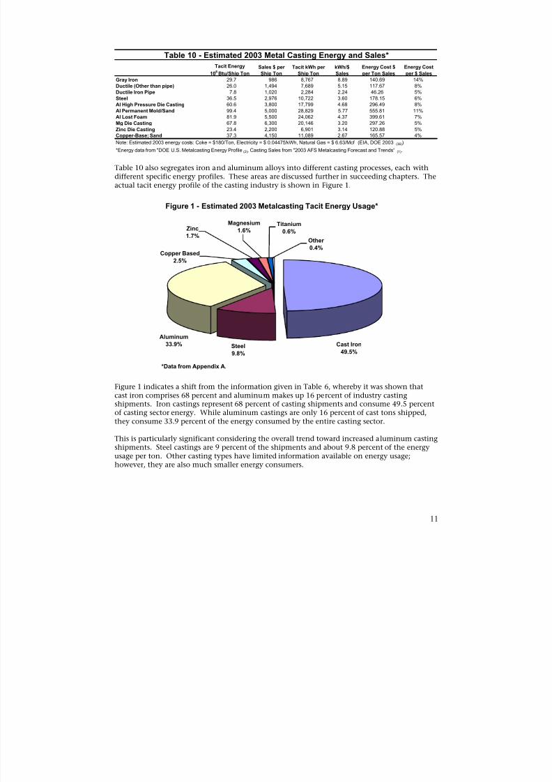
Table 10 also segregates iron and aluminum alloys into different casting processes, each withdifferent specific energy profiles. These areas are discussed further in succeeding chapters. Theactual tacit energy profile of the casting industry is shown in Figure 1.
Figure 1 - Estimated 2003 Metalcasting Tacit Energy Usage*
Magnesium TitaniumZinc 1.6% 0.6%1.7%
Other 0.4%
Copper Based 2.5%
Aluminum
33.9% Steel
9.8%
Cast Iron
49.5%
*Data from Appendix A.
Figure 1 indicates a shift from the information given in Table 6, whereby it was shown thatcast iron comprises 68 percent and aluminum makes up 16 percent of industry castingshipments. Iron castings represent 68 percent of casting shipments and consume 49.5 percentof casting sector energy. While aluminum castings are only 16 percent of cast tons shipped,
they consume 33.9 percent of the energy consumed by the entire casting sector.
This is particularly significant considering the overall trend toward increased aluminum castingshipments. Steel castings are 9 percent of the shipments and about 9.8 percent of the energyusage per ton. Other casting types have limited information available on energy usage;however, they are also much smaller energy consumers.
11
8/13/2019 Doebestpractice Casting
http://slidepdf.com/reader/full/doebestpractice-casting 13/116
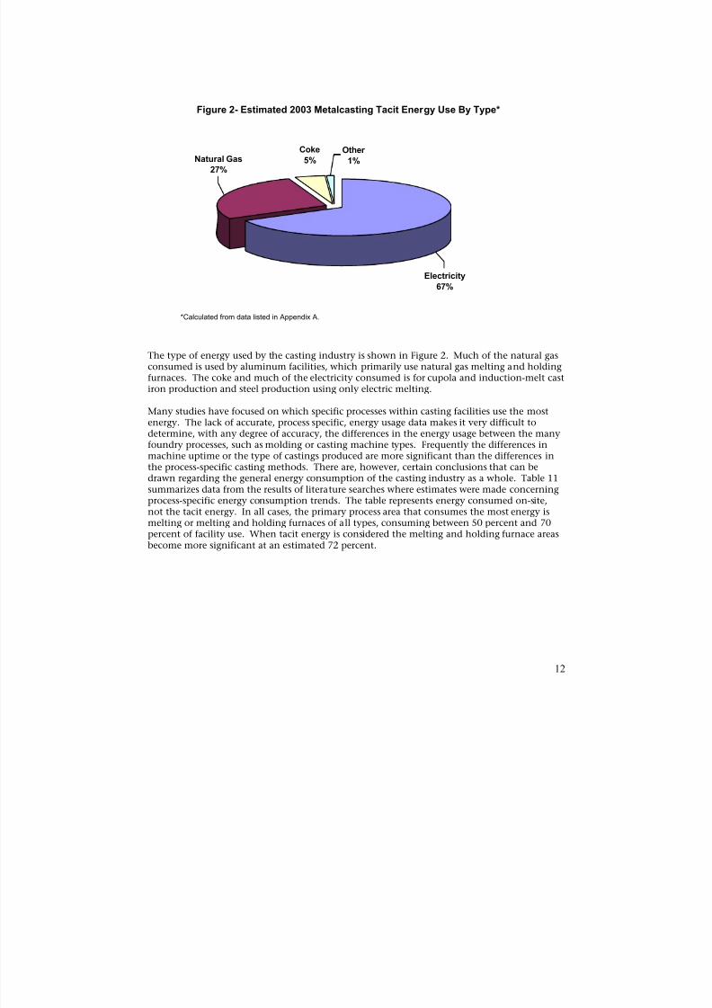
Figure 2- Estimated 2003 Metalcasting Tacit Energy Use By Type*
Coke
5%
Other
1%Natural Gas
27%
Electricity
67%
*Calculated from data listed in Appendix A.
The type of energy used by the casting industry is shown in Figure 2. Much of the natural gasconsumed is used by aluminum facilities, which primarily use natural gas melting and holdingfurnaces. The coke and much of the electricity consumed is for cupola and induction-melt castiron production and steel production using only electric melting.
Many studies have focused on which specific processes within casting facilities use the mostenergy. The lack of accurate, process specific, energy usage data makes it very difficult todetermine, with any degree of accuracy, the differences in the energy usage between the manyfoundry processes, such as molding or casting machine types. Frequently the differences inmachine uptime or the type of castings produced are more significant than the differences inthe process-specific casting methods. There are, however, certain conclusions that can bedrawn regarding the general energy consumption of the casting industry as a whole. Table 11summarizes data from the results of literature searches where estimates were made concerningprocess-specific energy consumption trends. The table represents energy consumed on-site,not the tacit energy. In all cases, the primary process area that consumes the most energy ismelting or melting and holding furnaces of all types, consuming between 50 percent and 70percent of facility use. When tacit energy is considered the melting and holding furnace areas
become more significant at an estimated 72 percent.
12
8/13/2019 Doebestpractice Casting
http://slidepdf.com/reader/full/doebestpractice-casting 14/116
Table 11 - Survey of Delivered Energy Usage by Metalcasting Process AreasMold or Heat
Study Melt & Hold Mold/Core Core Treat Clean General
Foundry Energy Management, 1990 (9) 64% 3% 3% 9% 21%
Large Auto, (Gray and Ductile Iron) 2001* 50% 15% 7% 9% 19%Department of Energy/Cast Metal Coalition
(All alloys) 58%Energy Conservation in Steel Foundry, PMI AFS 92-01 60% 23% 17%
Energy Conservation in Iron Foundries,India 2000 (16) 70% 15% 15%
Energy and Environmental Profile of theU.S. Metalcasting Industry 2002 (4)
55% 12% 8% 6% 7% 12%
Energy Profile and Reduction of Specific 58%Consumption of Energy in the Foundry(15)
* General was estimated and Mold/Core includes line holding furnaces.
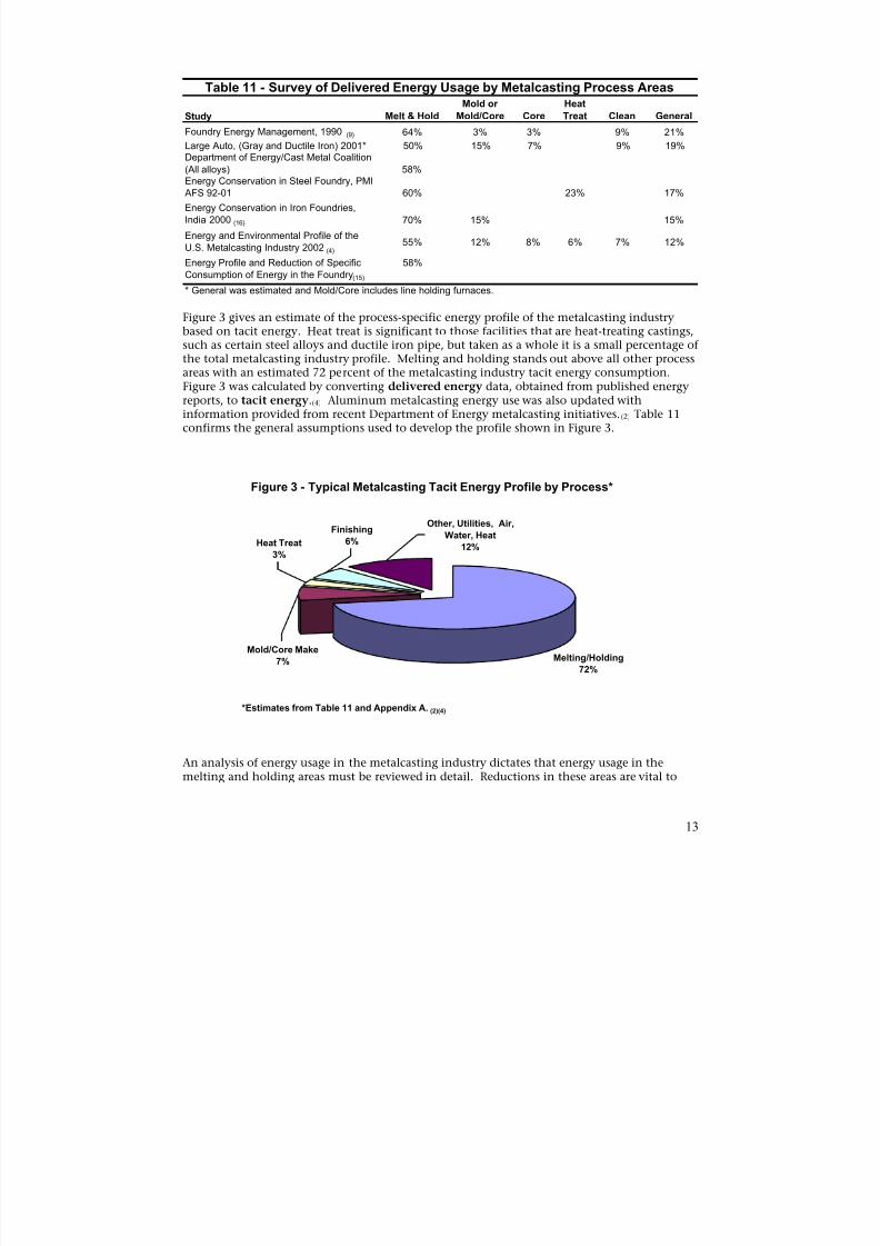
Figure 3 gives an estimate of the process-specific energy profile of the metalcasting industry
based on tacit energy. Heat treat is significant to those facilities that are heat-treating castings,such as certain steel alloys and ductile iron pipe, but taken as a whole it is a small percentage ofthe total metalcasting industry profile. Melting and holding stands out above all other processareas with an estimated 72 percent of the metalcasting industry tacit energy consumption.Figure 3 was calculated by converting delivered energy data, obtained from published energyreports, to tacit energy.(4) Aluminum metalcasting energy use was also updated withinformation provided from recent Department of Energy metalcasting initiatives.(2) Table 11confirms the general assumptions used to develop the profile shown in Figure 3.
Figure 3 - Typical Metalcasting Tacit Energy Profile by Process*
Other, Utilities, Air,
*Estimates from Table 11 and Appendix A. (2)(4)
Melting/Holding
72%
Mold/Core Make
7%
Heat Treat
3%
Finishing
6%Water, Heat
12%
An analysis of energy usage in the metalcasting industry dictates that energy usage in themelting and holding areas must be reviewed in detail. Reductions in these areas are vital to
13

8/13/2019 Doebestpractice Casting
http://slidepdf.com/reader/full/doebestpractice-casting 15/116
making significant reductions in the metalcasting industry’s overall energy usage. Anexamination of heat treat operations is needed in the metal alloy sectors.
14
8/13/2019 Doebestpractice Casting
http://slidepdf.com/reader/full/doebestpractice-casting 16/116
CHAPTER 1. MELTING
Section 1 of Chapter 1 covers the theoretical minimum energy required to melt one ton ofmetal by alloy type. This analysis determined the energy required to melt metal without anyconsideration for conversion efficiencies or yield considerations. This section also gives thetheoretical energy calculations to raise iron and steel to heat treat temperatures. Section 2covers the identified best practices and industry averages used by the industry today in meltingmetal. The best practice is derived from actual metalcasting facility data, where available, orsupplier data, absent facility data. Best practice represents the best performance actually beingachieved in operating metalcasting facilities. The industry average is considered the averageenergy being consumed by metalcasting facilities to melt one ton of iron. Section 3 covers thespecific energy improvements identified in Sections 1 and 2, and converts these improvementsinto energy and CO2 reductions.
SECTION 1. THEORETICAL MINIMUM
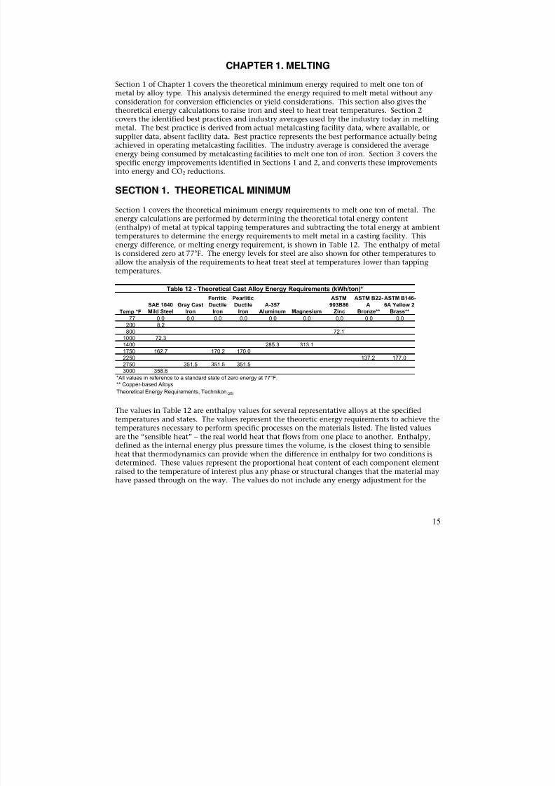
Section 1 covers the theoretical minimum energy requirements to melt one ton of metal. Theenergy calculations are performed by determining the theoretical total energy content(enthalpy) of metal at typical tapping temperatures and subtracting the total energy at ambienttemperatures to determine the energy requirements to melt metal in a casting facility. Thisenergy difference, or melting energy requirement, is shown in Table 12. The enthalpy of metalis considered zero at 77°F. The energy levels for steel are also shown for other temperatures toallow the analysis of the requirements to heat treat steel at temperatures lower than tappingtemperatures.
Table 12 - Theoretical Cast Alloy Energy Requirements (kWh/ton)*
Ferritic Pearlitic ASTM ASTM B22- ASTM B146SAE 1040 Gray Cast Ductile Ductile A-357 903B86 A 6A Yellow 2
Temp °F Mild Steel Iron Iron Iron Aluminum Magnesium Zinc Bronze** Brass**
77 0.0 0.0 0.0 0.0 0.0 0.0 0.0 0.0 0.0200 8.2800 72.1
1000 72.31400 285.3 313.11750 162.7 170.2 170.02250 137.2 177.02750 351.5 351.5 351.53000 358.6
*All values in reference to a standard state of zero energy at 77°F. ** Copper-based Alloys Theoretical Energy Requirements, Technikon (28)
The values in Table 12 are enthalpy values for several representative alloys at the specifiedtemperatures and states. The values represent the theoretic energy requirements to achieve thetemperatures necessary to perform specific processes on the materials listed. The listed valuesare the “sensible heat” – the real world heat that flows from one place to another. Enthalpy,defined as the internal energy plus pressure times the volume, is the closest thing to sensibleheat that thermodynamics can provide when the difference in enthalpy for two conditions isdetermined. These values represent the proportional heat content of each component elementraised to the temperature of interest plus any phase or structural changes that the material mayhave passed through on the way. The values do not include any energy adjustment for the
15
8/13/2019 Doebestpractice Casting
http://slidepdf.com/reader/full/doebestpractice-casting 17/116
solution of the alloying elements in the base metal solvent, or further interaction betweenalloying elements.
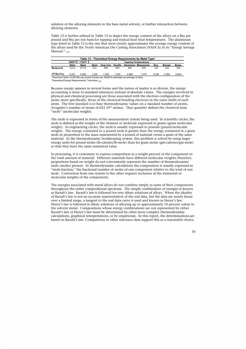
Table 12 is further refined in Table 13 to depict the energy content of the alloys on a Btu perpound and Btu per ton basis for tapping and typical heat treat temperatures. The aluminumtype listed in Table 13 is the one that most closely approximates the average energy content of
the alloys used by the North American Die Casting Association (NADCA) in its “Energy SavingsManual.” (12)
Steel Steel Steel Gray Iron Ductile Aluminum Magnesium Zinc Bronze Brass
Btu/pound 123.5 277.8 612 600 600 493 535 123 234 302
106 Btu/Ton 0.247 0.556 1.225 1.200 1.200 0.986 1.070 0.246 0.469 0.604
1000°F 1750°F
Table 13 - Theoretical Energy Requirements by Metal Type*Tapping Temperatures
*Aluminum factor of 493 Btu per pound chosen per NADCA estimates as average Al alloy.
Theoretical Energy Requirements, Technikon (28)
Because energy appears in several forms and the nature of matter is so diverse, the energyaccounting is done to standard references instead of absolute values. The energies involved inphysical and chemical processing are those associated with the electron configuration of theatom; more specifically, those of the chemical bonding electrons in the outer shells of eachatom. The first standard is to base thermodynamic values on a standard number of atoms,Avogadro’s number of atoms (6.023 1023 atoms). That quantity defines the chemical term“mole” (molecular weight).
The mole is expressed in terms of the measurement system being used. In scientific circles, themole is defined as the weight of the element or molecule expressed in grams (gram molecularweight). In engineering circles, the mole is usually expressed in pounds (pound molecularweight). The energy contained in a pound mole is greater than the energy contained in a grammole in proportion to the mass represented by a pound of material versus a gram of the samematerial. In the thermodynamic bookkeeping system, this problem is solved by using larger
energy units for pound moles (lb-calories/lb-mole) than for gram moles (gm-calories/gm-mole)so that they have the same numerical value.
In processing, it is customary to express composition as a weight percent of the component tothe total amount of material. Different materials have different molecular weights; therefore,proportions based on weight do not conveniently represent the number of thermodynamicunits (moles) present. In thermodynamic calculations the composition is usually expressed as“mole fraction,” the fractional number of moles of one component relative to the total of onemole. Conversion from one system to the other requires inclusion of the elemental ormolecular weights of the components.
The energies associated with metal alloys do not combine simply as sums of their components
throughout the entire compositional spectrum. The simple combination of energies is knownas Raoult’s law. Raoult’s law is followed for very dilute solutions of alloys. When the idealityof Raoult’s law is not an accurate representation of the real data, but the data are nearly linearover a limited range, a tangent to the real data curve is used and known as Henry’s law.Henry’s law is followed in dilute solutions of alloying up to approximately 10 percent solute inthe solvent metal. Compositions whose energy combinations are not represented by eitherRaoult’s law or Henry’s law must be determined by other more complex thermodynamiccalculations, graphical interpretations, or by empiricism. In this report, the determinations arebased on Raoult’s law. Comparisons to other reference data support this as a reasonable choice.
16
8/13/2019 Doebestpractice Casting
http://slidepdf.com/reader/full/doebestpractice-casting 18/116
E n t h a l p y ,
K W H / T o n o f e l e m e n t
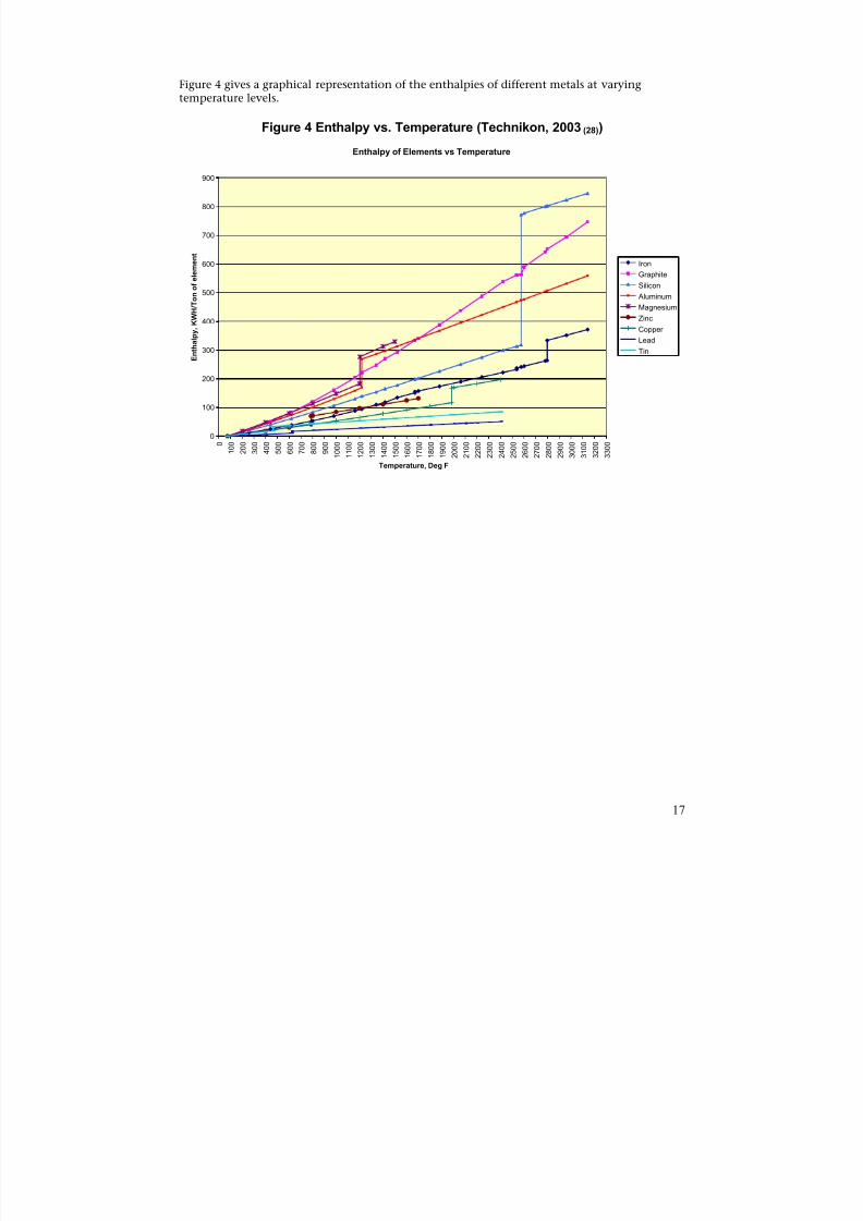
Figure 4 gives a graphical representation of the enthalpies of different metals at varyingtemperature levels.
Figure 4 Enthalpy vs. Temperature (Technikon, 2003(28))
Enthalpy of Elements vs Temperature
900
800
700
0
100
200
300
400
500
600
0
1 0 0
2 0 0
3 0 0
4 0 0
5 0 0
6 0 0
7 0 0
8 0 0
9 0 0
1 0 0 0
1 1 0 0
1 2 0 0
1 3 0 0
1 4 0 0
1 5 0 0
1 6 0 0
1 7 0 0
1 8 0 0
1 9 0 0
2 0 0 0
2 1 0 0
2 2 0 0
2 3 0 0
2 4 0 0
2 5 0 0
2 6 0 0
2 7 0 0
2 8 0 0
2 9 0 0
3 0 0 0
3 1 0 0
3 2 0 0
3 3 0 0
Temperature, Deg F
Iron
Graphite
Silicon
Aluminum
Magnesium
Zinc
CopperLead
Tin
17
8/13/2019 Doebestpractice Casting
http://slidepdf.com/reader/full/doebestpractice-casting 19/116
SECTION 2 – BEST PRACTICE
IRON CASTINGS – MELTING
Iron casting production represents 68 percent of the metalcasting production tons shipped andconsumes 49.5 percent of the energy. The melting methods utilized by iron metalcasting
facilities are primarily cupola and induction furnace melting. Induction furnaces (EIF), and tosome extent resistance heating, are also used for holding furnaces between melting and castinglines to smooth out metallurgical variations and for temperature control or superheating metalafter melt. There are also several arc melting furnaces (EAF) in use by iron facilities, but theseare not discussed in this report due to the small number utilized by iron facilities.
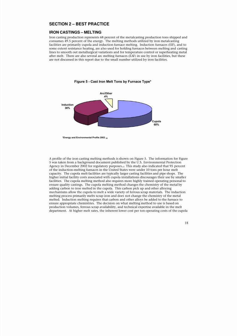
Figure 5 - Cast Iron Melt Tons by Furnace Type*
Arc/Other4%
Cupola60%
Induction36%
*Energy and Environmental Profile 2003 (4)
A profile of the iron casting melting methods is shown on Figure 5. The information for Figure5 was taken from a background document published by the U.S. Environmental ProtectionAgency in December 2002 for regulatory purposes.(5) This study also indicated that 95 percentof the induction-melting furnaces in the United States were under 10 tons per hour meltcapacity. The cupola melt facilities are typically larger casting facilities and pipe shops. Thehigher initial facility costs associated with cupola installations discourages their use by smaller
facilities. The cupola melting method also requires more highly trained operating personal toensure quality castings. The cupola melting method changes the chemistry of the metal byadding carbon to iron melted in the cupola. This carbon pick up and other alloyingmechanisms allow the cupola to melt a wide variety of ferrous scrap materials. The inductionmelting process primarily melts scrap iron and does not change the chemistry of the metalmelted. Induction melting requires that carbon and other alloys be added to the furnace toensure appropriate chemistries. The decision on what melting method to use is based onproduction volumes, ferrous scrap availability, and technical expertise available in the meltdepartment. At higher melt rates, the inherent lower cost per ton operating costs of the cupola
18

8/13/2019 Doebestpractice Casting
http://slidepdf.com/reader/full/doebestpractice-casting 20/116
8/13/2019 Doebestpractice Casting
http://slidepdf.com/reader/full/doebestpractice-casting 21/116
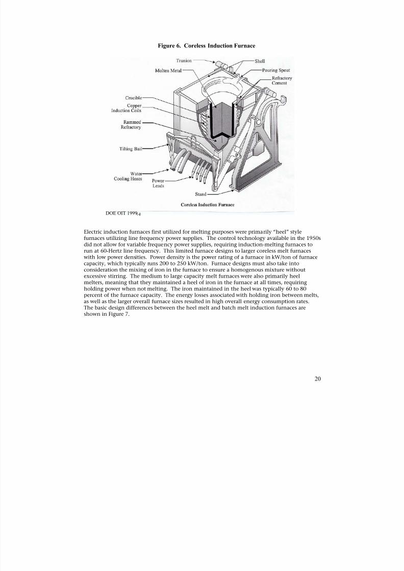
Figure 6. Coreless Induction Furnace
DOE OIT 1999 4
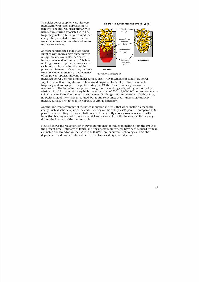
Electric induction furnaces first utilized for melting purposes were primarily “heel” stylefurnaces utilizing line frequency power supplies. The control technology available in the 1950sdid not allow for variable frequency power supplies, requiring induction-melting furnaces torun at 60-Hertz line frequency. This limited furnace designs to larger coreless melt furnaceswith low power densities. Power density is the power rating of a furnace in kW/ton of furnacecapacity, which typically runs 200 to 250 kW/ton. Furnace designs must also take intoconsideration the mixing of iron in the furnace to ensure a homogenous mixture withoutexcessive stirring. The medium to large capacity melt furnaces were also primarily heelmelters, meaning that they maintained a heel of iron in the furnace at all times, requiringholding power when not melting. The iron maintained in the heel was typically 60 to 80percent of the furnace capacity. The energy losses associated with holding iron between melts,as well as the larger overall furnace sizes resulted in high overall energy consumption rates.
The basic design differences between the heel melt and batch melt induction furnaces areshown in Figure 7.
20
8/13/2019 Doebestpractice Casting
http://slidepdf.com/reader/full/doebestpractice-casting 22/116
The older power supplies were also very Figure 7. Induction Melting Furnace Typesinefficient, with losses approaching 40percent. The heel was used primarily to Metallic
help reduce stirring associated with line Charge
frequency melting, but also required that
charges be preheated to ensure that no Water-Cooledwet charges were put into the molten iron Induction
in the furnace heel. Coils
As more sophisticated solid-state powerMolten Metal
Heelsupplies with increasingly higher powerratings became available, the “batch”furnace increased in numbers. A batch- Refractory Batch Melter
melting furnace empties the furnace aftereach melt cycle, reducing the holding
Lined Steel
Shell
power requirements. Over time, methods Heel Melter
were developed to increase the frequency
of the power supplies, allowing for
KERAMIDA, Indianapolis, IN
increased power densities and smaller furnace sizes. Advancements in solid-state powersupplies, as well as computer controls, allowed engineers to develop infinitely variablefrequency and voltage power supplies during the 1990s. These new designs allow themaximum utilization of furnace power throughout the melting cycle, with good control ofstirring. Small furnaces with very high power densities of 700 to 1,000 kW/ton can now melt acold charge in 30 to 35 minutes. Since the metallic charge is not immersed in a bath of iron,no preheating of the charge is required, but is still sometimes used. Preheating can helpincrease furnace melt rates at the expense of energy efficiency.
Another inherent advantage of the batch induction melter is that when melting a magneticcharge such as solid scrap iron, the coil efficiency can be as high as 95 percent, compared to 80
percent when heating the molten bath in a heel melter. Hysteresis losses associated withinduction heating of a solid ferrous material are responsible for this increased coil efficiencyduring the first part of the melting cycle.
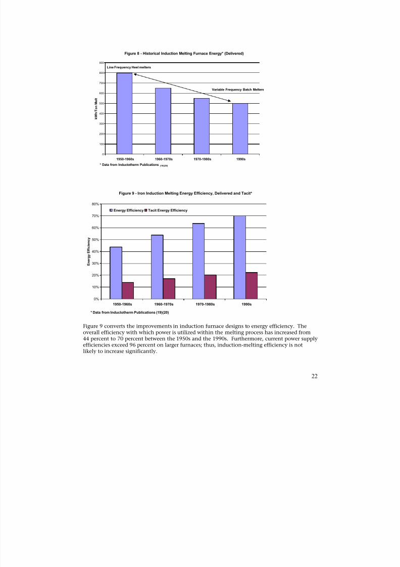
Figure 8 shows the reductions of energy requirements for induction melting from the 1950s tothe present time. Estimates of typical melting energy requirements have been reduced from anestimated 800 kWh/ton in the 1950s to 500 kWh/ton for current technologies. This chartdepicts delivered power to show differences in furnace design considerations.
21
8/13/2019 Doebestpractice Casting
http://slidepdf.com/reader/full/doebestpractice-casting 23/116
Figure 8 - Historical Induction Melting Furnace Energy* (Delivered)
900
Line Frequency Heel melters
800
700
1950-1960s 1960-1970s 1970-1980s 1990s
Variable Frequency Batch Melters
k W h / T o n M e l t
600
500
400
300
200
100
0
* Data from Inductotherm Publications (19)(20)
Figure 9 - Iron Induction Melting Energy Efficiency, Delivered and Tacit*
0%
10%
20%
30%
40%
50%
60%
70%
80%
E n e r g y E f f i c i e n c y
Energy Efficiency Tacit Energy Efficiency
1950-1960s 1960-1970s 1970-1980s 1990s
* Data from Inductotherm Publications (19)(20)
Figure 9 converts the improvements in induction furnace designs to energy efficiency. Theoverall efficiency with which power is utilized within the melting process has increased from44 percent to 70 percent between the 1950s and the 1990s. Furthermore, current power supplyefficiencies exceed 96 percent on larger furnaces; thus, induction-melting efficiency is notlikely to increase significantly.
22
8/13/2019 Doebestpractice Casting
http://slidepdf.com/reader/full/doebestpractice-casting 24/116
Tacit energy efficiencies increased from 14 percent to 22 percent during the same period.The tacit energy efficiency is also shown in Figure 9 and takes into consideration power plantefficiency, as well as transmission losses.
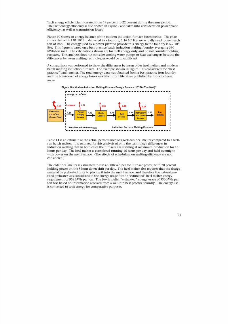
Figure 10 shows an energy balance of the modern induction furnace batch melter. The chartshows that with 1.81 106 Btu delivered to a foundry, 1.16 106 Btu are actually used to melt each
ton of iron. The energy used by a power plant to provide this energy to the foundry is 5.7 106
Btu. This figure is based on a best practice batch induction melting foundry averaging 530kWh/ton melt. The calculations shown are for melt energy only and do not consider holdingfurnaces. This analysis does not consider cooling water pumps or heat exchangers because thedifferences between melting technologies would be insignificant.
A comparison was performed to show the differences between older heel melters and modernbatch melting induction furnaces. The example shown in Figure 10 is considered the “bestpractice” batch melter. The total energy data was obtained from a best practice iron foundryand the breakdown of energy losses was taken from literature published by Inductotherm.
(19)(20).
Figure 10 - Modern Induction Melting Process Energy Balance (106
Btu/Ton Melt)*
Energy 1.81 106Btu
Power
Supply
Losses
Electricity
5.7 106Btu
(Power Plant)
3.890.08
Cable
Losses
0.02
1.81 1.73Coil
Losses
1.71
0.26
Refractory
and Cover
Losses
0.29
1.45 1.16 Iron
Melting
Losses
*Data from Inductotherm(19)(20) Induction Furnace Melting Process
Table 14 is an estimate of the actual performance of a well-run heel melter compared to a well-run batch melter. It is assumed for this analysis of only the technology differences ininduction melting that in both cases the furnaces are running at maximum production for 16hours per day. The heel melter is considered running 16 hours per day and held overnightwith power on the melt furnace. (The effects of scheduling on melting efficiency are notconsidered.)
The older heel melter is estimated to run at 800kWh per ton furnace power, with 20 percentholding power on the 8 hour down shift per day. The heel melter also requires that the chargematerial be preheated prior to placing it into the melt furnace, and therefore the natural gas-
fired preheater was considered in the energy usage for the “estimated” heel melter energyrequirement of 954 kWh per ton. The batch melter “estimated” energy usage of 530 kWh perton was based on information received from a well-run best practice foundry. The energy useis converted to tacit energy for comparative purposes.
23
8/13/2019 Doebestpractice Casting
http://slidepdf.com/reader/full/doebestpractice-casting 25/116
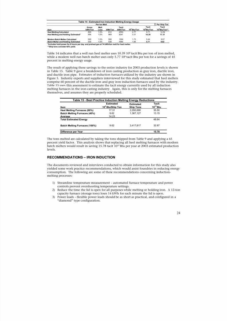
Table 14 - Estimated Iron Induction Melting Energy UsagePer ton Melt Per Ship Ton
Gross Melt Tacit Tacit Tacit
Item kWh/Ton Loss kWh/Ton kWh/Ton 106 Btu/Ton 106Btu/Ton 106Btu/Ton**
Heel Melting Calculated 800 1.5% 812 2550 2.77 8.71 14.52 Heel Melting and Holding Estimated* 954 1.5% 969 3041 3.31 10.39 17.31 Modern Batch Melter Calculated 500 1.5% 508 1594 1.73 5.44 9.07 Batch Melter and Holding Estimated 530 1.5% 538 1690 1.84 5.77 9.62 *Includes hold power for 8 hours per day and preheat gas at 74 kWh/ton melt for heel melter. **Ship tons consider 60% yield.
Table 14 indicates that a well run heel melter uses 10.39 106 tacit Btu per ton of iron melted,while a modern well run batch melter uses only 5.77 106 tacit Btu per ton for a savings of 45percent in melting energy usage.
The result of applying these savings to the entire industry for 2003 production levels is shownin Table 15. Table 9 gave a breakdown of iron casting production as gray iron, ductile iron,and ductile iron pipe. Estimates of induction furnaces utilized by the industry are shown inFigure 5. Industry experts and suppliers interviewed for this study estimated that heel melterscomprise 60 percent of the ductile iron and gray iron induction furnaces used by the industry.
Table 15 uses this assessment to estimate the tacit energy currently used by all inductionmelting furnaces in the iron casting industry. Again, this is only for the melting furnacesthemselves, and assumes they are properly scheduled.
Table 15 - Best Practice Induction Melting Energy Reductions
Item
Heel Melting Furnaces (60%)
Batch Melting Furnaces (40%)
Average
Total Estimated Energy
Estimated
106
Btu/Ship Ton
17.31
9.62
14.23
EstimatedShip Tons
2,050,690
1,367,127
Tacit
1012
Btu
35.50
13.15
48.64
Batch Melting Furnaces (100%) 9.62 3,417,817 32.87
Difference per Year 15.78
The tons melted are calculated by taking the tons shipped from Table 9 and applying a 65percent yield factor. This analysis shows that replacing all heel melting furnaces with modernbatch melters would result in saving 15.78 tacit 1012 Btu per year at 2003 estimated productionlevels.
RECOMMENDATIONS – IRON INDUCTION
The documents reviewed and interviews conducted to obtain information for this study alsoyielded some work practice recommendations, which would assist foundries in reducing energy
consumption. The following are some of these recommendations concerning induction-melting processes:
1) Streamline temperature measurement – automated furnace temperature and powercontrols prevent overshooting temperature settings.
2) Reduce the time the lid is open for all purposes while melting or holding iron. A 12-toncapacity furnace (storage tons) loses 14 kWh for each minute the lid is open.
3) Power leads – flexible power leads should be as short as practical, and configured in a“diamond” type configuration.
24
8/13/2019 Doebestpractice Casting
http://slidepdf.com/reader/full/doebestpractice-casting 26/116
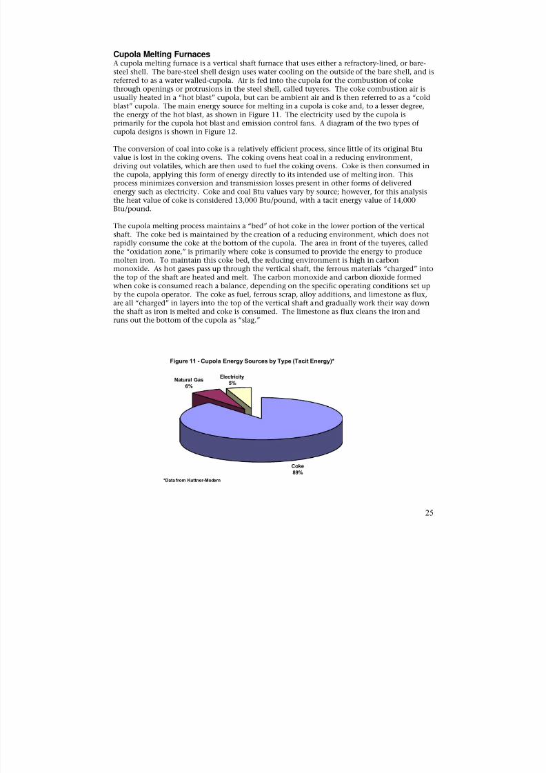
Cupola Melting FurnacesA cupola melting furnace is a vertical shaft furnace that uses either a refractory-lined, or bare-steel shell. The bare-steel shell design uses water cooling on the outside of the bare shell, and isreferred to as a water walled-cupola. Air is fed into the cupola for the combustion of cokethrough openings or protrusions in the steel shell, called tuyeres. The coke combustion air isusually heated in a “hot blast” cupola, but can be ambient air and is then referred to as a “cold
blast” cupola. The main energy source for melting in a cupola is coke and, to a lesser degree,the energy of the hot blast, as shown in Figure 11. The electricity used by the cupola isprimarily for the cupola hot blast and emission control fans. A diagram of the two types ofcupola designs is shown in Figure 12.
The conversion of coal into coke is a relatively efficient process, since little of its original Btuvalue is lost in the coking ovens. The coking ovens heat coal in a reducing environment,driving out volatiles, which are then used to fuel the coking ovens. Coke is then consumed inthe cupola, applying this form of energy directly to its intended use of melting iron. Thisprocess minimizes conversion and transmission losses present in other forms of deliveredenergy such as electricity. Coke and coal Btu values vary by source; however, for this analysisthe heat value of coke is considered 13,000 Btu/pound, with a tacit energy value of 14,000
Btu/pound.
The cupola melting process maintains a “bed” of hot coke in the lower portion of the verticalshaft. The coke bed is maintained by the creation of a reducing environment, which does notrapidly consume the coke at the bottom of the cupola. The area in front of the tuyeres, calledthe “oxidation zone,” is primarily where coke is consumed to provide the energy to producemolten iron. To maintain this coke bed, the reducing environment is high in carbonmonoxide. As hot gases pass up through the vertical shaft, the ferrous materials “charged” intothe top of the shaft are heated and melt. The carbon monoxide and carbon dioxide formedwhen coke is consumed reach a balance, depending on the specific operating conditions set upby the cupola operator. The coke as fuel, ferrous scrap, alloy additions, and limestone as flux,are all “charged” in layers into the top of the vertical shaft and gradually work their way down
the shaft as iron is melted and coke is consumed. The limestone as flux cleans the iron andruns out the bottom of the cupola as “slag.”
Figure 11 - Cupola Energy Sources by Type (Tacit Energy)*
Natural GasElectricity
5%6%
Coke89%
*Data from Kuttner-Modern
25

8/13/2019 Doebestpractice Casting
http://slidepdf.com/reader/full/doebestpractice-casting 27/116
The cupola operating parameters, controlled by the cupola operator, can vary the height of thecoke bed and thereby change the carbon pick up and other metallurgical properties of the iron.In this way, both the metallic charge make up, and alloys added, as well as the operatingparameter of the cupola affect the metallurgical properties of the molten iron produced. This isan overly simplified description of the cupola melting operation, but it should suffice for thefollowing energy use discussions.
The cupola has the advantages of being able to change the metallurgical properties of iron, aswell as use coke as fuel. It can also melt many different forms of ferrous scrap not suited forinduction furnace melting operations. The reducing environment, however, results in highcarbon monoxide content in the stack gases passing up through the charge materials. Thishigh carbon monoxide content and, to a lesser extent, the temperature of the stack gases isenergy lost as the stack gases are exhausted from the upper stack. This waste gas stream alsocontains small amounts of hydrogen and other volatile organics from the coke and certaintypes of ferrous scrap. The carbon monoxide generated is not the result of a poor combustionprocess, but a characteristic of a properly running cupola. The exhaust gases leaving the top ofthe cupola have a high particulate loading, and therefore add-on pollution control equipmentis required. Modern day cupolas also burn the carbon monoxide and volatiles in afterburners,
which are usually required by local environmental regulations.
Cupola designs have changed dramatically during the past 40 years. During the 1960s, cupolasused refractory-lined shells with no water cooling, and heated blast air was only beginning tobe applied to cupola melting installations. The problem with this design was that the cupolamelting campaign was limited to about 16 hours. This was due to the limited refractory life ofthe brick used to line the cupola shells. It was typical to use two cupolas, side-by-side, tosupply iron to foundry lines 16 hours each day. Then, to fill the need to run longer productioncampaigns, water-walled cupolas were developed that could run for more than two weekscontinuously without major repairs. This design used a high volume of water on the outside ofthe steel shell without a refractory lining. The cooling effect of the water on the bare shellrequired additional energy to be supplied by coke in the charge; however, the savings inherent
in running long campaign cupolas far outweighed the additional cost of coke.
26
8/13/2019 Doebestpractice Casting
http://slidepdf.com/reader/full/doebestpractice-casting 28/116
Upper Stack (Water Jacket) Water-cooled Bare
Steel Shell (High-Volume Water Cooling)
Wind Box (Combustion Air Supply, Gas Fired Preheat)
Tuyeres(Combustion Air)
Molten Iron
Molten Iron
Coke Bed
Melt Zone
Preheat Zone
Charge Materials:
CokeMetallics
LimestoneMetallurgical Alloys
Exhaust Air to Emission
Control System
Refractory-linedSteel Shell (Low-Volume
Water Cooling)
Molten Iron
Coke Bed
Melt Zone
Wind Box (Combustion
Air Supply, Recouperative
Preheat)
Extended Preheat Zone
Molten Iron
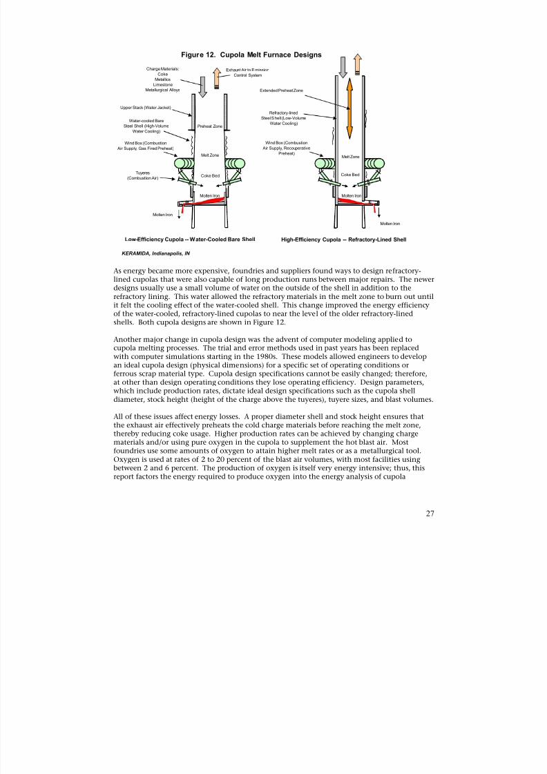
Figure 12. Cupola Melt Furnace Designs
Low-Efficiency Cupola -- Water-Cooled Bare Shell High-Efficiency Cupola -- Refractory-Lined Shell
KERAMIDA, Indianapolis, IN
As energy became more expensive, foundries and suppliers found ways to design refractory-lined cupolas that were also capable of long production runs between major repairs. The newerdesigns usually use a small volume of water on the outside of the shell in addition to therefractory lining. This water allowed the refractory materials in the melt zone to burn out untilit felt the cooling effect of the water-cooled shell. This change improved the energy efficiency
of the water-cooled, refractory-lined cupolas to near the level of the older refractory-linedshells. Both cupola designs are shown in Figure 12.
Another major change in cupola design was the advent of computer modeling applied tocupola melting processes. The trial and error methods used in past years has been replacedwith computer simulations starting in the 1980s. These models allowed engineers to developan ideal cupola design (physical dimensions) for a specific set of operating conditions orferrous scrap material type. Cupola design specifications cannot be easily changed; therefore,at other than design operating conditions they lose operating efficiency. Design parameters,which include production rates, dictate ideal design specifications such as the cupola shelldiameter, stock height (height of the charge above the tuyeres), tuyere sizes, and blast volumes.
All of these issues affect energy losses. A proper diameter shell and stock height ensures thatthe exhaust air effectively preheats the cold charge materials before reaching the melt zone,thereby reducing coke usage. Higher production rates can be achieved by changing chargematerials and/or using pure oxygen in the cupola to supplement the hot blast air. Mostfoundries use some amounts of oxygen to attain higher melt rates or as a metallurgical tool.Oxygen is used at rates of 2 to 20 percent of the blast air volumes, with most facilities usingbetween 2 and 6 percent. The production of oxygen is itself very energy intensive; thus, thisreport factors the energy required to produce oxygen into the energy analysis of cupola
27
8/13/2019 Doebestpractice Casting
http://slidepdf.com/reader/full/doebestpractice-casting 29/116
operations. The oxygen energy shown in this report represents energy used to produce theoxygen delivered, and not energy consumed by foundries themselves.
These newer cupola designs have been installed in several new cupola installations in recentyears. The cost of rebuilding a cupola is quite high and as a result of this high capital cost,most cupolas have not been modified to the most energy efficient designs available.
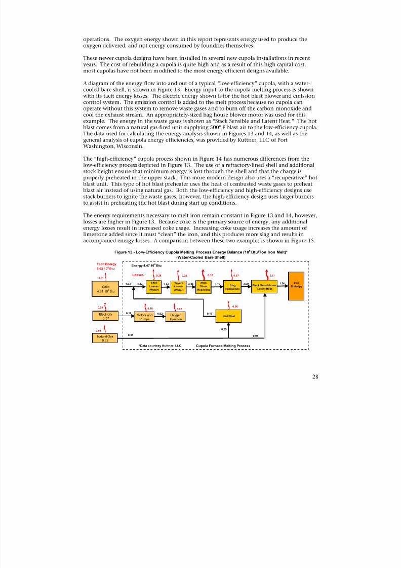
A diagram of the energy flow into and out of a typical “low-efficiency” cupola, with a water-cooled bare shell, is shown in Figure 13. Energy input to the cupola melting process is shownwith its tacit energy losses. The electric energy shown is for the hot blast blower and emissioncontrol system. The emission control is added to the melt process because no cupola canoperate without this system to remove waste gases and to burn off the carbon monoxide andcool the exhaust stream. An appropriately-sized bag house blower motor was used for thisexample. The energy in the waste gases is shown as “Stack Sensible and Latent Heat.” The hotblast comes from a natural gas-fired unit supplying 500° F blast air to the low-efficiency cupola.The data used for calculating the energy analysis shown in Figures 13 and 14, as well as thegeneral analysis of cupola energy efficiencies, was provided by Kuttner, LLC of PortWashington, Wisconsin.
The “high-efficiency” cupola process shown in Figure 14 has numerous differences from thelow-efficiency process depicted in Figure 13. The use of a refractory-lined shell and additionalstock height ensure that minimum energy is lost through the shell and that the charge isproperly preheated in the upper stack. This more modern design also uses a “recuperative” hotblast unit. This type of hot blast preheater uses the heat of combusted waste gases to preheatblast air instead of using natural gas. Both the low-efficiency and high-efficiency designs usestack burners to ignite the waste gases, however, the high-efficiency design uses larger burnersto assist in preheating the hot blast during start up conditions.
The energy requirements necessary to melt iron remain constant in Figure 13 and 14, however,losses are higher in Figure 13. Because coke is the primary source of energy, any additional
energy losses result in increased coke usage. Increasing coke usage increases the amount oflimestone added since it must “clean” the iron, and this produces more slag and results inaccompanied energy losses. A comparison between these two examples is shown in Figure 15.
Figure 13 - Low-Efficiency Cupola Melting Process Energy Balance (106 Btu/Ton Iron Melt)*
(Water-Cooled Bare Shell)
Coke
4.34 106 Btu
Natural Gas0.32
Shell
Losses
(Water)
0.28
Tuyere
Losses
(Water)
0.08
3.94 Slag
Production
3.76
0.07
Stack Sensible and
Latent Heat
2.51
3.69 1.24 Iron
Enthalpy
Losses
*Data courtesy Kuttner, LLC Cupola Furnace Melting Process
Electricity0.37
0.19
Misc.
Chem.
Reactions
4.22
0.10
Motors and
Pumps
0.10
Hot Blast
0.06
3.86
0.01
0.25
0.31
Energy 4.47 106
BtuTacit Energy
5.03 106 Btu
4.03
0.12
0.31
Oxygen
Injection
0.02
0.02
0.06
0.25
28
8/13/2019 Doebestpractice Casting
http://slidepdf.com/reader/full/doebestpractice-casting 30/116
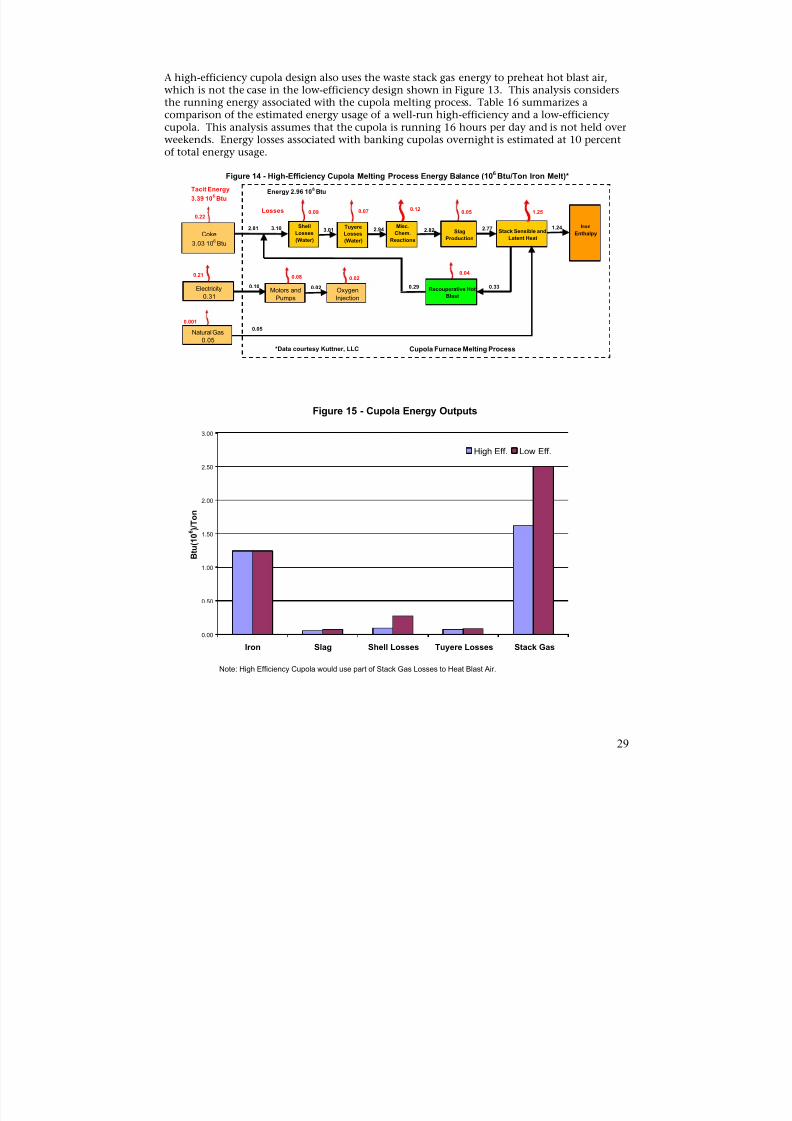
A high-efficiency cupola design also uses the waste stack gas energy to preheat hot blast air,which is not the case in the low-efficiency design shown in Figure 13. This analysis considersthe running energy associated with the cupola melting process. Table 16 summarizes acomparison of the estimated energy usage of a well-run high-efficiency and a low-efficiencycupola. This analysis assumes that the cupola is running 16 hours per day and is not held overweekends. Energy losses associated with banking cupolas overnight is estimated at 10 percent
of total energy usage.
Figure 14 - High-Efficiency Cupola Melting Process Energy Balance (106 Btu/Ton Iron Melt)*
Tacit Energy Energy 2.96 106
Btu3.39 10
6Btu
0.12Losses 0.09 0.07 0.05 1.250.22
Shell
Losses
(Water)Coke
3.03 106 Btu
Tuyere
Losses
(Water)
3.01 Slag
Production
2.82 Stack Sensible and
Latent Heat
2.77 1.24 Iron
Enthalpy
Electricity
0.31
Natural Gas0.05
0.330.29
Misc.
Chem.
Reactions
3.10
Motors andPumps
0.08
Recouperative Hot
Blast
0.04
2.94
0.001
0.21
2.81
0.10
0.05
OxygenInjection
0.02
0.02
*Data courtesy Kuttner, LLC Cupola Furnace Melting Process
Figure 15 - Cupola Energy Outputs
0.00
0.50
1.00
1.50
2.00
2.50
3.00
B t u ( 1 0 6 ) / T o n
High Eff. Low Eff.
Iron Slag Shell Losses Tuyere Losses Stack Gas
Note: High Efficiency Cupola would use part of Stack Gas Losses to Heat Blast Air.
29
8/13/2019 Doebestpractice Casting
http://slidepdf.com/reader/full/doebestpractice-casting 31/116
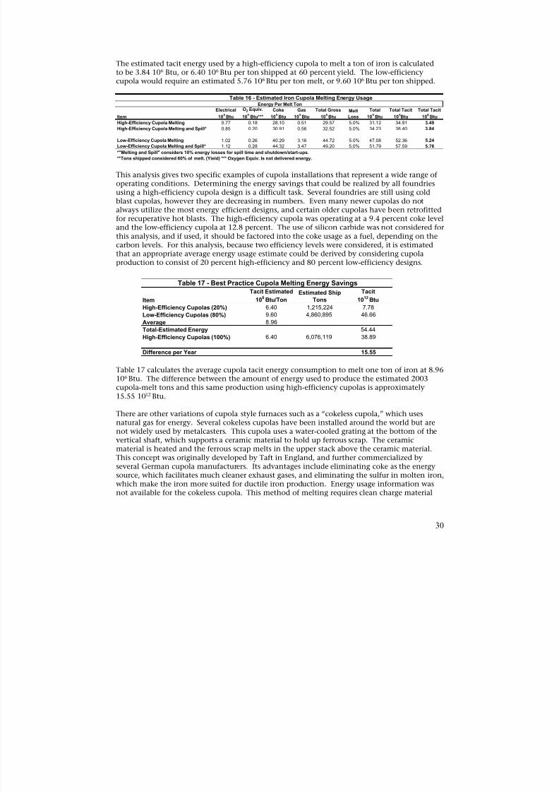
The estimated tacit energy used by a high-efficiency cupola to melt a ton of iron is calculatedto be 3.84 106 Btu, or 6.40 106 Btu per ton shipped at 60 percent yield. The low-efficiencycupola would require an estimated 5.76 106 Btu per ton melt, or 9.60 106 Btu per ton shipped.
Table 16 - Estimated Iron Cupola Melting Energy Usage
Electrical O2 Equiv. Coke Gas
Energy Per Melt Ton
Total Gross Melt Total Total Tacit Total Tacit
Item 105Btu 10
5 Btu*** 10
5Btu 10
5Btu 10
5Btu Loss 10
5Btu 10
5Btu 10
6Btu
High-Efficiency Cupola Melting 0.77 0.18 28.10 0.51 29.57 5.0% 31.12 34.91 3.49 High-Efficiency Cupola Melting and Spill* 0.85 0.20 30.91 0.56 32.52 5.0% 34.23 38.40 3.84 Low-Efficiency Cupola Melting 1.02 0.26 40.29 3.16 44.72 5.0% 47.08 52.36 5.24 Low-Efficiency Cupola Melting and Spill* 1.12 0.28 44.32 3.47 49.20 5.0% 51.79 57.59 5.76 *"Melting and Spill" considers 10% energy losses for spill time and shutdown/start-ups. **Tons shipped considered 60% of melt. (Yield) *** Oxygen Equiv. Is not delivered energy.
This analysis gives two specific examples of cupola installations that represent a wide range ofoperating conditions. Determining the energy savings that could be realized by all foundriesusing a high-efficiency cupola design is a difficult task. Several foundries are still using coldblast cupolas, however they are decreasing in numbers. Even many newer cupolas do notalways utilize the most energy efficient designs, and certain older cupolas have been retrofittedfor recuperative hot blasts. The high-efficiency cupola was operating at a 9.4 percent coke leveland the low-efficiency cupola at 12.8 percent. The use of silicon carbide was not considered forthis analysis, and if used, it should be factored into the coke usage as a fuel, depending on thecarbon levels. For this analysis, because two efficiency levels were considered, it is estimatedthat an appropriate average energy usage estimate could be derived by considering cupolaproduction to consist of 20 percent high-efficiency and 80 percent low-efficiency designs.
Table 17 - Best Practice Cupola Melting Energy Savings
Item
Tacit Estimated
106 Btu/TonEstimated Ship
Tons
Tacit
1012 Btu
High-Efficiency Cupolas (20%) 6.40 1,215,224 7.78
Low-Efficiency Cupolas (80%) 9.60 4,860,895 46.66
Average 8.96Total-Estimated Energy 54.44
High-Efficiency Cupolas (100%) 6.40 6,076,119 38.89
Difference per Year 15.55
Table 17 calculates the average cupola tacit energy consumption to melt one ton of iron at 8.96106 Btu. The difference between the amount of energy used to produce the estimated 2003cupola-melt tons and this same production using high-efficiency cupolas is approximately15.55 1012 Btu.
There are other variations of cupola style furnaces such as a “cokeless cupola,” which usesnatural gas for energy. Several cokeless cupolas have been installed around the world but arenot widely used by metalcasters. This cupola uses a water-cooled grating at the bottom of thevertical shaft, which supports a ceramic material to hold up ferrous scrap. The ceramicmaterial is heated and the ferrous scrap melts in the upper stack above the ceramic material.This concept was originally developed by Taft in England, and further commercialized byseveral German cupola manufacturers. Its advantages include eliminating coke as the energysource, which facilitates much cleaner exhaust gases, and eliminating the sulfur in molten iron,which make the iron more suited for ductile iron production. Energy usage information wasnot available for the cokeless cupola. This method of melting requires clean charge material
30
8/13/2019 Doebestpractice Casting
http://slidepdf.com/reader/full/doebestpractice-casting 32/116
and also requires that carbon be added to the molten iron, depending on the type of ferrousscrap. The cokeless cupola will not superheat iron, so an external form of superheating isrequired.
RECOMMENDATIONS – CUPOLA MELT
Replacing cupolas and support equipment is capital-intensive. As energy prices continue toclimb, this approach may be justifiable in many instances. Absent a complete replacement,certain changes or procedures can be implemented to reduce energy usage:
1) Dehumidify blast air to achieve coke savings and better metallurgical control, especiallyin hot humid locations. One pound of water removed will save approximately 1.2pounds of coke.
2) Use a covered coke storage area to prevent water from being introduced into the charge.One pound of water removed will save approximately 1.2 pounds of coke.
3) Keep the upper stack full. Maximum charge levels increase preheating of metals andreduce coke usage. Varying stack levels also cause metallurgical variations; maintainingconstant stack levels decreases metallurgical variations.
4) Maintain a continuous melting operation. Spill time increases energy losses and causesmetallurgical variations. Consider changing the cupola lining’s inside diameter andtuyere’s diameter if extended levels of low – or high – melt rates are expected.
5) Replace water-walled shells with refractory-lined shells.6) Reduce pollution control equipment horsepower requirements. (Minimize the size of
charge door opening on above charge take offs or convert to below charge take off.)7) Install inverter controlled drives on large motors, such as hot blast blower and air
pollution control equipment exhaust motors, in place of dampers or waste gates(variable frequency and variable voltage). The use of these drive packages can save 50percent of energy requirements, with reductions of 20 percent in motor speed.
8) Replace gas-fired hot blasts with recuperative hot blasts.9) Maintain hot blasts and ductwork to ensure that maximum temperature and air volume
reaches the cupola with minimum losses.
These work practice energy savings included suggestions from the “Metal Melting EfficiencyProject,” CCMA, Technikon, 2001. (23)
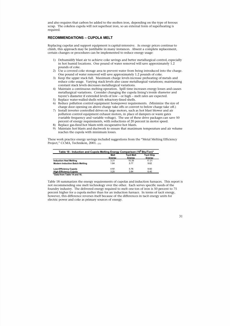
Table 18 - Induction and Cupola Melting Energy Comparison (106Btu/Ton)*
Melt Tacit Melt Tacit Ship
Energy Energy Energy
Induction Heel Melting 3.31 10.39 17.31
Modern Induction Batch Melting 1.84 5.77 9.62
Low-Efficiency CupolaHigh-Efficiency Cupola
4.923.25
5.763.84
9.606.40
*Data from Table 14 and 16.
Table 18 summarizes the energy requirements of cupolas and induction furnaces. This report isnot recommending one melt technology over the other. Each serves specific needs of thefoundry industry. The delivered energy required to melt one ton of iron is 50 percent to 75percent higher for a cupola melter than for an induction furnace. In terms of tacit energy,however, this difference reverses itself because of the differences in tacit energy units forelectric power and coke as primary sources of energy.
31
8/13/2019 Doebestpractice Casting
http://slidepdf.com/reader/full/doebestpractice-casting 33/116
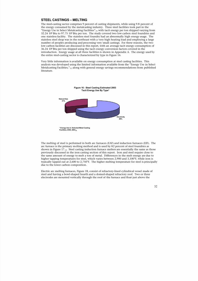
STEEL CASTINGS – MELTINGThe steel-casting sector comprises 9 percent of casting shipments, while using 9.8 percent ofthe energy consumed by the metalcasting industry. Three steel facilities took part in the“Energy Use in Select Metalcasting Facilities”(2) with tacit energy per ton shipped varying from32.24 106 Btu to 97.75 106 Btu per ton. The study covered two low carbon steel foundries and
one stainless facility. The stainless steel foundry had an abnormally high energy usage. Thestainless steel shop was in the northeast with a very high heating load and employing a largenumber of peoples producing and processing very small castings. For these reasons, the twolow carbon facilities are discussed in this report, with an average tacit energy consumption of36.24 106 Btu per ton shipped using the tacit energy conversion factors covered in theintroduction. Energy usage at all three facilities is shown in Appendix A. The energy used bythe entire steel-casting sector is characterized by type in Figure 16.
Very little information is available on energy consumption at steel casting facilities. Thisanalysis was developed using the limited information available from the “Energy Use in SelectMetalcasting Facilities,”(2) along with general energy savings recommendations from publishedliterature.
Figure 16 - Steel Casting Estimated 2003Tacit Energy Use By Type*
* Energy Use in Selected Metal Casting Facilities, DOE, 2003(2)
The melting of steel is performed in both arc furnaces (EAF) and induction furnaces (EIF). Thearc furnace is the primary melting method and is used by 82 percent of steel foundries asshown in Figure 17.(6) Steel casting induction furnace melters are essentially the same as those
previously discussed in the iron casting section of this report. Iron and steel require close tothe same amount of energy to melt a ton of metal. Differences in the melt energy are due tohigher tapping temperatures for steel, which varies between 2,900 and 3,100°F, while iron istypically tapped out at 2,600 to 2,750°F. The higher melting temperature for steel is principallydue to the lower carbon composition.
Electric arc melting furnaces, Figure 18, consist of refractory-lined cylindrical vessel made ofsteel and having a bowl-shaped hearth and a domed-shaped refractory roof. Two or threeelectrodes are mounted vertically through the roof of the furnace and float just above the
Electricity69%
Natural Gas31%
32
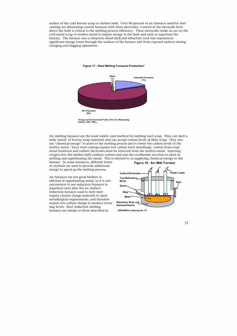
8/13/2019 Doebestpractice Casting
http://slidepdf.com/reader/full/doebestpractice-casting 34/116
surface of the cold ferrous scrap or molten bath. Over 80 percent of arc furnaces used for steelcastings are alternating current furnaces with three electrodes. Control of the electrode levelabove the bath is critical to the melting process efficiency. These electrodes strike an arc on thecold metal scrap or molten metal to impart energy to the bath and melt or superheat thefurnace. The furnace uses a refractory-lined shell and refractory roof, but experiencessignificant energy losses through the surfaces of the furnace and from exposed surfaces during
charging and slagging operations.
Figure 17 - Steel Melting Furnaces Production*
OtherInduction Furnaces
1%17%
Arc Furnaces82%
*Energy and Environmental Profile of the U.S. MetalcastingIndustry, DOE, 1999(4)
Arc melting furnaces are the most widely used method for melting steel scrap. They can melt awide variety of ferrous scrap materials and can accept certain levels of dirty scrap. They alsouse “chemical energy” to assist in the melting process and to lower the carbon levels of themolten metal. Since steel castings require low carbon level metallurgy, carbon from scrapmetal feedstock and carbon electrodes must be removed from the molten metal. Injectingoxygen into the molten bath oxidizes carbon and uses the exothermic reaction to assist inmelting and superheating the metal. This is referred to as supplying chemical energy to thefurnace. In some instances, different forms Figure 18. Arc Melt Furnaceof oxyfuels are used to provide additionalenergy to speed up the melting process.
Arc furnaces are not good holders or
efficient at superheating metal, so it is notuncommon to use induction furnaces tosuperheat steel after the arc melters.Induction furnaces used to melt steelrequire cleaner charge materials to meetmetallurgical requirements, and thereforerequire low carbon charge to produce lowerslag levels. Steel induction meltingfurnaces are similar to those described in KERAMIDA, Indianapolis, IN
Power Leads
Top (Refractory
Brick)Spout
Carbon Electrodes
Door
Refractory Brick and
Rammed Hearth
Metal
Slag
33

8/13/2019 Doebestpractice Casting
http://slidepdf.com/reader/full/doebestpractice-casting 35/116
Chapter 1, Section 2, Induction Furnaces while an electric arc melting furnace is shown inFigure 18.
The two example foundry profiles documented in Appendix A, show that the inductionfurnace shop used tacit energy of 32.24 106 Btu per ton shipped and the arc furnace shoprequired 40.70 106 Btu. This is contrary to the overall analysis of the facilities, which indicated
that the arc-melting furnace requires 450 kWh to melt one ton of steel, whereby the typicalinduction furnace requires 530 to 600 kWh per ton (5.77 to 6.54 106 Btu per ton tacit energy.)Tapping temperatures may have been lower, but the process likely involved chemical energy toassist the electric melting.
The energy use differences between the two facilities studied are probably not attributable tothe melting furnace used to melt the scrap metal. It is evident from communications withindustry experts that few differences exist between the two furnaces’ total energy requirement.A casting yield survey conducted in 1997 by the Steel Founders Society of America (SFSA)included energy data on arc furnaces. A report based on this survey published in AFSTransactions, “Current State of Casting Yield,”(17) included a survey of melting energyconsumption, which indicated that steel arc furnaces required 6.45 106 Btu of tacit energy to
melt one ton of steel or 14.16 106
Btu per ton shipped.
Little information is available to indicate best practice facilities or processes for steel castings.The steel casting industry has been struggling to survive for many years and has not investedheavily in new technology. Methods of improving the efficiency of arc melting furnaces in theprimary steel industry are not directly transferable to the smaller furnaces used by the steelcasting producers. For example, oxygen enriched burner and foaming slag projects are notconsidered effective on the smaller furnaces typical of steel foundry operations. There is a needto review the melting methods used by the steel casting industry and provide economicalmethods of improving melting energy consumption.
RECOMMENDATIONS – STEEL MELTING
The literature review and interviews conducted for this study did yield the following generalwork practices that can assist steel foundries in improving existing furnace energy usage:
1) Automate and refine electrode level controls to provide maximum power capabilitiesthroughout the melt cycle.
2) Minimize the time the lid is open for charging and the time the door is open forremoving slag.
ALUMINUM CASTINGS – MELTINGAluminum casting facilities were forecast to ship 16 percent of total castings produced during2003. Although aluminum facilities ship only 16 percent of the castings, this sector consumes33.9 percent of the energy. Aluminum facilities consume between 60.56 106 Btu and 99.36 106
Btu tacit energy per ton of castings shipped, as discussed in the “Energy Use in SelectMetalcasting Facilities”(2) and documented in Appendix A.
The energy used in a typical aluminum die casting facility is shown in Figure 19. Die castingfacilities were forecast to ship approximately 70 percent of the aluminum casting shipments in2003, as shown in Table 9 (pg. 10).
Molten aluminum used in aluminum casting facilities is supplied by either melting thealuminum in-house, or by bringing it in molten from a secondary aluminum facility.
34
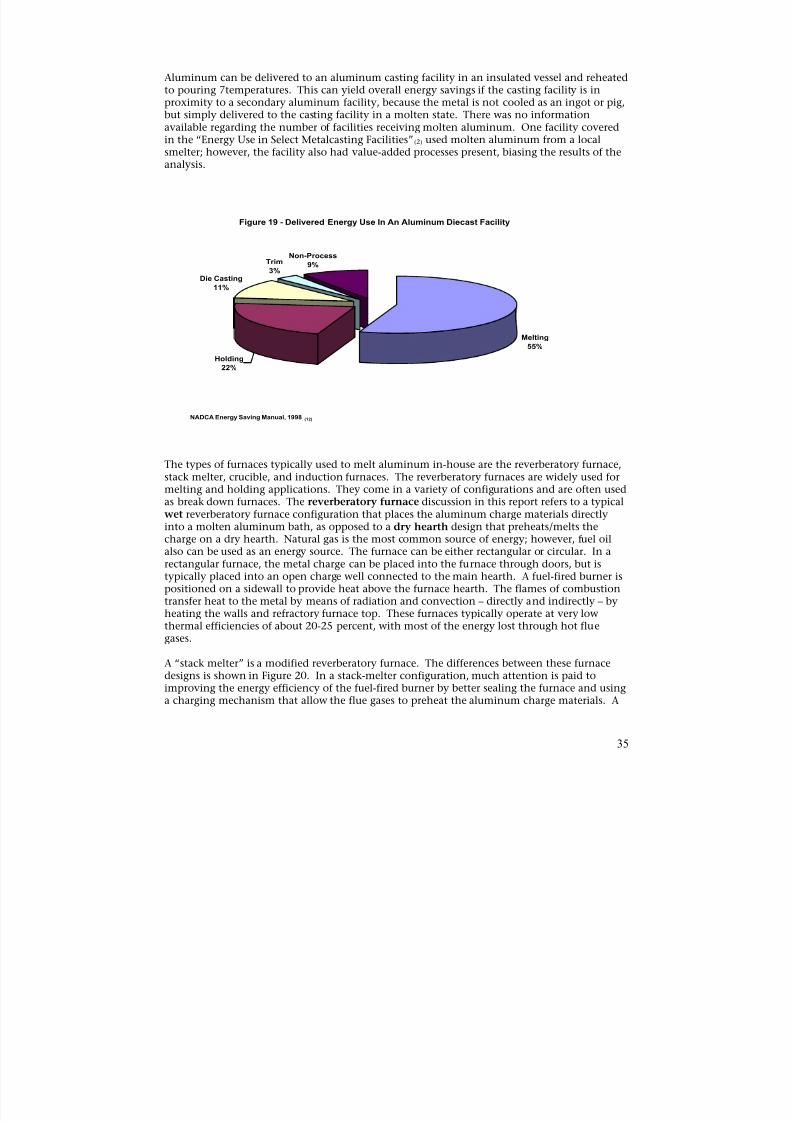
8/13/2019 Doebestpractice Casting
http://slidepdf.com/reader/full/doebestpractice-casting 36/116
Aluminum can be delivered to an aluminum casting facility in an insulated vessel and reheatedto pouring 7temperatures. This can yield overall energy savings if the casting facility is inproximity to a secondary aluminum facility, because the metal is not cooled as an ingot or pig,but simply delivered to the casting facility in a molten state. There was no informationavailable regarding the number of facilities receiving molten aluminum. One facility coveredin the “Energy Use in Select Metalcasting Facilities”(2) used molten aluminum from a local
smelter; however, the facility also had value-added processes present, biasing the results of theanalysis.
Figure 19 - Delivered Energy Use In An Aluminum Diecast Facility
Non-Process Trim 9%
Melting
55%
Die Casting
11%
3%
Holding
22%
NADCA Energy Saving Manual, 1998 (12)
The types of furnaces typically used to melt aluminum in-house are the reverberatory furnace,stack melter, crucible, and induction furnaces. The reverberatory furnaces are widely used formelting and holding applications. They come in a variety of configurations and are often usedas break down furnaces. The reverberatory furnace discussion in this report refers to a typicalwet reverberatory furnace configuration that places the aluminum charge materials directlyinto a molten aluminum bath, as opposed to a dry hearth design that preheats/melts thecharge on a dry hearth. Natural gas is the most common source of energy; however, fuel oilalso can be used as an energy source. The furnace can be either rectangular or circular. In arectangular furnace, the metal charge can be placed into the furnace through doors, but istypically placed into an open charge well connected to the main hearth. A fuel-fired burner ispositioned on a sidewall to provide heat above the furnace hearth. The flames of combustion
transfer heat to the metal by means of radiation and convection – directly and indirectly – byheating the walls and refractory furnace top. These furnaces typically operate at very lowthermal efficiencies of about 20-25 percent, with most of the energy lost through hot fluegases.
A “stack melter” is a modified reverberatory furnace. The differences between these furnacedesigns is shown in Figure 20. In a stack-melter configuration, much attention is paid toimproving the energy efficiency of the fuel-fired burner by better sealing the furnace and usinga charging mechanism that allow the flue gases to preheat the aluminum charge materials. A
35
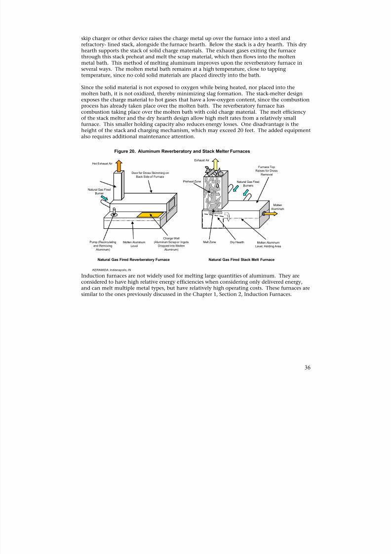
8/13/2019 Doebestpractice Casting
http://slidepdf.com/reader/full/doebestpractice-casting 37/116
skip charger or other device raises the charge metal up over the furnace into a steel andrefractory- lined stack, alongside the furnace hearth. Below the stack is a dry hearth. This dryhearth supports the stack of solid charge materials. The exhaust gases exiting the furnacethrough this stack preheat and melt the scrap material, which then flows into the moltenmetal bath. This method of melting aluminum improves upon the reverberatory furnace inseveral ways. The molten metal bath remains at a high temperature, close to tapping
temperature, since no cold solid materials are placed directly into the bath.
Since the solid material is not exposed to oxygen while being heated, nor placed into themolten bath, it is not oxidized, thereby minimizing slag formation. The stack-melter designexposes the charge material to hot gases that have a low-oxygen content, since the combustionprocess has already taken place over the molten bath. The reverberatory furnace hascombustion taking place over the molten bath with cold charge material. The melt efficiencyof the stack melter and the dry hearth design allow high melt rates from a relatively smallfurnace. This smaller holding capacity also reduces energy losses. One disadvantage is theheight of the stack and charging mechanism, which may exceed 20 feet. The added equipmentalso requires additional maintenance attention.
Figure 20. Aluminum Reverberatory and Stack Melter Furnaces
Hot Exhaust Air
Door for Dross Skimming on Back Side of Furnace
Natural Gas Fired Burner
Charge Well Pump (Recirculating Molten Aluminum (Aluminum Scrap or Ingots Molten Aluminum
and Removing Level Dropped into Molten Level, Holding Area Aluminum) Aluminum)
Preheat Zone
Molten
Aluminum
Furnace TopRaises for Dross
Removal
Natural Gas FiredBurners
Exhaust Air
Dry HearthMelt Zone
Natural Gas Fired Reverberatory Furnace Natural Gas Fired Stack Melt Furnace
KERAMIDA, Indianapolis, IN
Induction furnaces are not widely used for melting large quantities of aluminum. They areconsidered to have high relative energy efficiencies when considering only delivered energy,and can melt multiple metal types, but have relatively high operating costs. These furnaces aresimilar to the ones previously discussed in the Chapter 1, Section 2, Induction Furnaces.
36
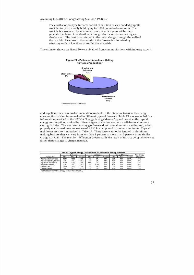
8/13/2019 Doebestpractice Casting
http://slidepdf.com/reader/full/doebestpractice-casting 38/116
According to NADCA “Energy Saving Manual,” 1998 (12):
The crucible or pot-type furnaces consist of cast iron or clay bonded graphitecrucibles (or pots) usually holding up to 1,000 pounds of aluminum. Thecrucible is surrounded by an annular space in which gas or oil burnersgenerate the flame of combustion, although electric resistance heating can
also be used. The heat is transferred to the metal charge through the walls ofthe crucible. Heat loss to the outside of the furnace is minimized byrefractory walls of low thermal conductive materials.
The estimates shown on Figure 20 were obtained from communications with industry experts
Figure 21 - Estimated Aluminum MeltingFurnaces Production*
Crucible andInduction
5%
Stack Melter
ReverberatoryFurnace
90%
5%
*Foundry Supplier Interviews
and suppliers; there was no documentation available in the literature to assess the energyconsumption of aluminum melted in different types of furnaces. Table 19 was assembled frominformation provided in the NADCA “Energy Savings Manual” (12) and describes the typicalenergy consumption required by different types of melting methods available to aluminumcasting facilities. The wet reverberatory gas furnace dominates aluminum melting and, whenproperly maintained, uses an average of 1,350 Btu per pound of molten aluminum. Typicalmelt losses are also summarized in Table 19. These losses cannot be ignored in aluminummelting because they can vary from less than 1 percent to more than 5 percent using similarcharge materials. The melt loss differences are primarily the result of furnace design differencesrather than changes in charge materials.
Table 19 - Typical Energy Consumption for Aluminum Melting Furnaces
Furnace TypeBtu/pound Melt Losses Energy Efficiency Tacit Energy
EfficiencyMin. Max. Average Min. Max. Average Min. Max. Average
Wet Reverberatory Gas
Wet Reverberatory ElectricDry Hearth Reverb GasInduction Coreless
Crucible GasCrucible Electric
1200 1500 1350
638 819 728.51000 1200 1100638 819 728.5
2500 7000 4750854 921 887.5
2% 5% 3.5%
1% 2% 1.5%1.5% 2% 1.8%1% 1.25% 1.1%
3% 4% 3.5%1% 2% 1.5%
32% 40% 36.0%
59% 76% 67.5%40% 48% 44.0%59% 76% 67.5%
7% 19% 13.0%52% 57% 54.5%
35%
21%43%21%
13%17%
Modified data from NADCA Energy Savings Manual 1998 (12)
37
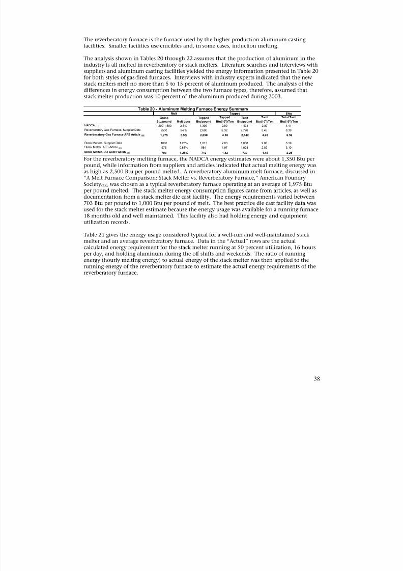
8/13/2019 Doebestpractice Casting
http://slidepdf.com/reader/full/doebestpractice-casting 39/116
The reverberatory furnace is the furnace used by the higher production aluminum castingfacilities. Smaller facilities use crucibles and, in some cases, induction melting.
The analysis shown in Tables 20 through 22 assumes that the production of aluminum in theindustry is all melted in reverberatory or stack melters. Literature searches and interviews withsuppliers and aluminum casting facilities yielded the energy information presented in Table 20
for both styles of gas-fired furnaces. Interviews with industry experts indicated that the newstack melters melt no more than 5 to 15 percent of aluminum produced. The analysis of thedifferences in energy consumption between the two furnace types, therefore, assumed thatstack melter production was 10 percent of the aluminum produced during 2003.
Gross
Btu/pound Melt Loss
Tapped
Btu/pound
Tapped
Btu(106)/Ton
Tacit
Btu/pound
Tacit
Btu(106)/Ton
Total Tacit
Btu(106)/Ton
NADCA (12) 1,200-1,500 2-5% 1,399 2.80 1,434 2.87 4.41
Reverberatory Gas Furnace, Supplier Data 2500 5-7% 2,660 5.32 2,726 5.45 8.39
Reverberatory Gas Furnace AFS Article (25) 1,975 5.5% 2,090 4.18 2,142 4.28 6.59
Stack Melters, Supplier Data 1000 1.25% 1,013 2.03 1,038 2.08 3.19
Stack Melter AFS Article (25) 975 0.88% 984 1.97 1,008 2.02 3.10
Stack Melter, Die Cast Facility (26)
703 1.25% 712 1.42 730 1.46 2.25
Ship
Table 20 - Aluminum Melting Furnace Energy SummaryMelt Tapped
For the reverberatory melting furnace, the NADCA energy estimates were about 1,350 Btu perpound, while information from suppliers and articles indicated that actual melting energy wasas high as 2,500 Btu per pound melted. A reverberatory aluminum melt furnace, discussed in“A Melt Furnace Comparison: Stack Melter vs. Reverberatory Furnace,” American FoundrySociety(25), was chosen as a typical reverberatory furnace operating at an average of 1,975 Btuper pound melted. The stack melter energy consumption figures came from articles, as well asdocumentation from a stack melter die cast facility. The energy requirements varied between703 Btu per pound to 1,000 Btu per pound of melt. The best practice die cast facility data wasused for the stack melter estimate because the energy usage was available for a running furnace18 months old and well maintained. This facility also had holding energy and equipmentutilization records.
Table 21 gives the energy usage considered typical for a well-run and well-maintained stackmelter and an average reverberatory furnace. Data in the “Actual” rows are the actualcalculated energy requirement for the stack melter running at 50 percent utilization, 16 hoursper day, and holding aluminum during the off shifts and weekends. The ratio of runningenergy (hourly melting energy) to actual energy of the stack melter was then applied to therunning energy of the reverberatory furnace to estimate the actual energy requirements of thereverberatory furnace.
38
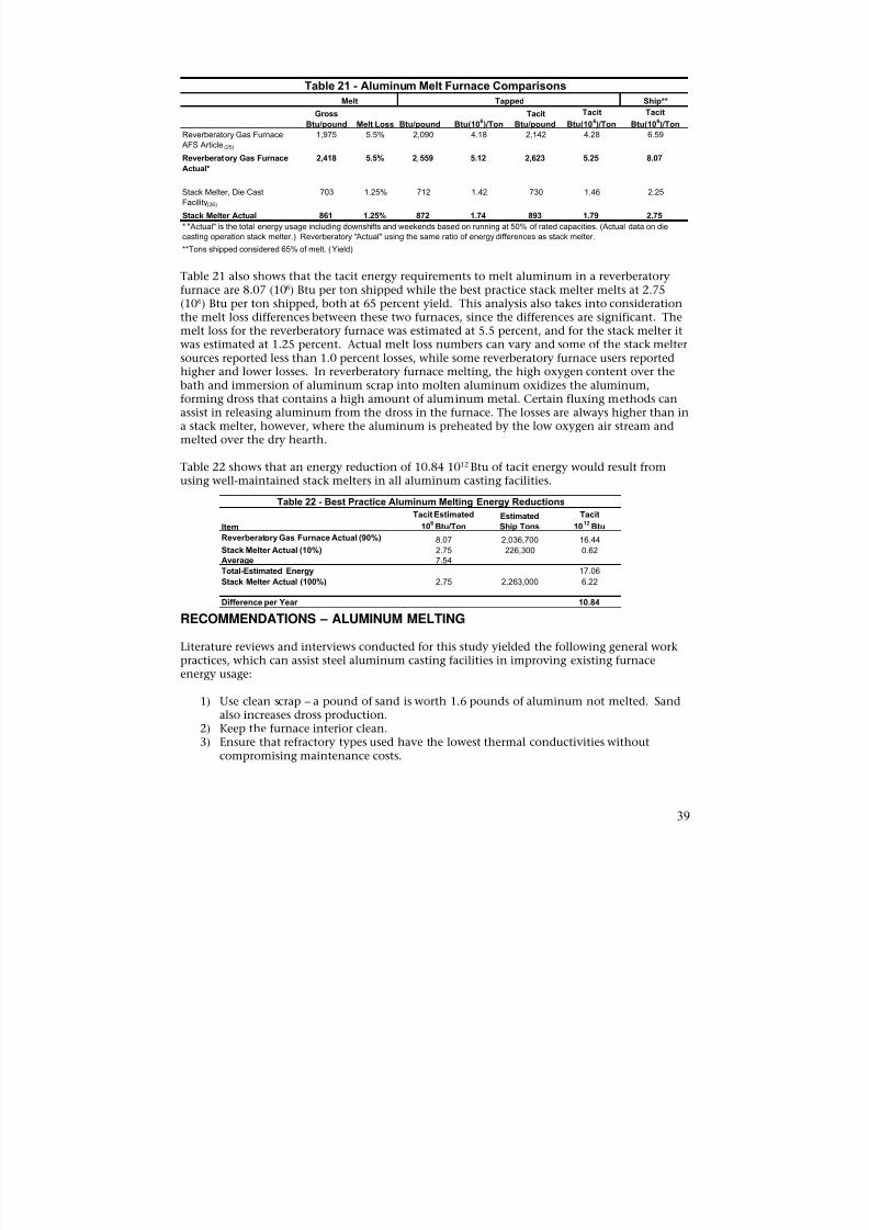
8/13/2019 Doebestpractice Casting
http://slidepdf.com/reader/full/doebestpractice-casting 40/116
Table 21 - Aluminum Melt Furnace ComparisonsShip**Melt Tapped
Gross Tacit Tacit Tacit Btu/pound Melt Loss Btu/pound Btu(10
6)/Ton Btu/pound Btu(10
6)/Ton Btu(10
6)/Ton
Reverberatory Gas Furnace 1,975 5.5% 2,090 4.18 2,142 4.28 6.59
AFS Article (25)
Reverberatory Gas Furnace 2,418 5.5% 2,559 5.12 2,623 5.25 8.07
Actual*
Stack Melter, Die Cast 703 1.25% 712 1.42 730 1.46 2.25
Facility(26)
Stack Melter Actual 861 1.25% 872 1.74 893 1.79 2.75
* "Actual" is the total energy usage including downshifts and weekends based on running at 50% of rated capacities. (Actual data on diecasting operation stack melter.) Reverberatory "Actual" using the same ratio of energy differences as stack melter.
**Tons shipped considered 65% of melt. (Yield)
Table 21 also shows that the tacit energy requirements to melt aluminum in a reverberatoryfurnace are 8.07 (106) Btu per ton shipped while the best practice stack melter melts at 2.75(106) Btu per ton shipped, both at 65 percent yield. This analysis also takes into considerationthe melt loss differences between these two furnaces, since the differences are significant. The
melt loss for the reverberatory furnace was estimated at 5.5 percent, and for the stack melter itwas estimated at 1.25 percent. Actual melt loss numbers can vary and some of the stack meltersources reported less than 1.0 percent losses, while some reverberatory furnace users reportedhigher and lower losses. In reverberatory furnace melting, the high oxygen content over thebath and immersion of aluminum scrap into molten aluminum oxidizes the aluminum,forming dross that contains a high amount of aluminum metal. Certain fluxing methods canassist in releasing aluminum from the dross in the furnace. The losses are always higher than ina stack melter, however, where the aluminum is preheated by the low oxygen air stream andmelted over the dry hearth.
Table 22 shows that an energy reduction of 10.84 1012 Btu of tacit energy would result fromusing well-maintained stack melters in all aluminum casting facilities.
Table 22 - Best Practice Aluminum Melting Energy ReductionsTacit Estimated Estimated Tacit
Item 106
Btu/Ton Ship Tons 1012
Btu
Reverberatory Gas Furnace Actual (90%) 8.07 2,036,700 16.44
Stack Melter Actual (10%) 2.75 226,300 0.62Average 7.54
Total-Estimated Energy 17.06
Stack Melter Actual (100%) 2.75 2,263,000 6.22
Difference per Year 10.84
RECOMMENDATIONS – ALUMINUM MELTING
Literature reviews and interviews conducted for this study yielded the following general work
practices, which can assist steel aluminum casting facilities in improving existing furnaceenergy usage:
1) Use clean scrap – a pound of sand is worth 1.6 pounds of aluminum not melted. Sandalso increases dross production.
2) Keep the furnace interior clean.3) Ensure that refractory types used have the lowest thermal conductivities without
compromising maintenance costs.
39
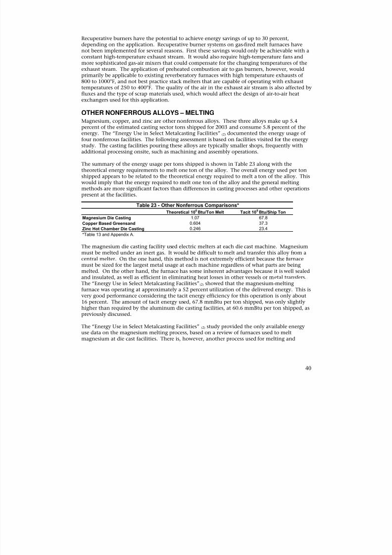
8/13/2019 Doebestpractice Casting
http://slidepdf.com/reader/full/doebestpractice-casting 41/116
Recuperative burners have the potential to achieve energy savings of up to 30 percent,depending on the application. Recuperative burner systems on gas-fired melt furnaces havenot been implemented for several reasons. First these savings would only be achievable with aconstant high-temperature exhaust stream. It would also require high-temperature fans andmore sophisticated gas-air mixers that could compensate for the changing temperatures of theexhaust steam. The application of preheated combustion air to gas burners, however, would
primarily be applicable to existing reverberatory furnaces with high temperature exhausts of800 to 1000°F, and not best practice stack melters that are capable of operating with exhausttemperatures of 250 to 400°F. The quality of the air in the exhaust air stream is also affected byfluxes and the type of scrap materials used, which would affect the design of air-to-air heatexchangers used for this application.
OTHER NONFERROUS ALLOYS – MELTING
Magnesium, copper, and zinc are other nonferrous alloys. These three alloys make up 5.4percent of the estimated casting sector tons shipped for 2003 and consume 5.8 percent of theenergy. The “Energy Use in Select Metalcasting Facilities” (2) documented the energy usage offour nonferrous facilities. The following assessment is based on facilities visited for the energystudy. The casting facilities pouring these alloys are typically smaller shops, frequently with
additional processing onsite, such as machining and assembly operations.
The summary of the energy usage per tons shipped is shown in Table 23 along with thetheoretical energy requirements to melt one ton of the alloy. The overall energy used per tonshipped appears to be related to the theoretical energy required to melt a ton of the alloy. Thiswould imply that the energy required to melt one ton of the alloy and the general meltingmethods are more significant factors than differences in casting processes and other operationspresent at the facilities.
Table 23 - Other Nonferrous Comparisons*
Theoretical 106 Btu/Ton Melt Tacit 106 Btu/Ship Ton
Magnesium Die Casting 1.07 67.8
Copper Based Greensand 0.604 37.3Zinc Hot Chamber Die Casting 0.246 23.4
*Table 13 and Appendix A.
The magnesium die casting facility used electric melters at each die cast machine. Magnesiummust be melted under an inert gas. It would be difficult to melt and transfer this alloy from acentral melter. On the one hand, this method is not extremely efficient because the furnacemust be sized for the largest metal usage at each machine regardless of what parts are beingmelted. On the other hand, the furnace has some inherent advantages because it is well sealedand insulated, as well as efficient in eliminating heat losses in other vessels or metal transfers.The “Energy Use in Select Metalcasting Facilities”(2) showed that the magnesium-meltingfurnace was operating at approximately a 52 percent utilization of the delivered energy. This isvery good performance considering the tacit energy efficiency for this operation is only about
16 percent. The amount of tacit energy used, 67.8 mmBtu per ton shipped, was only slightlyhigher than required by the aluminum die casting facilities, at 60.6 mmBtu per ton shipped, aspreviously discussed.
The “Energy Use in Select Metalcasting Facilities” (2) study provided the only available energyuse data on the magnesium melting process, based on a review of furnaces used to meltmagnesium at die cast facilities. There is, however, another process used for melting and
40
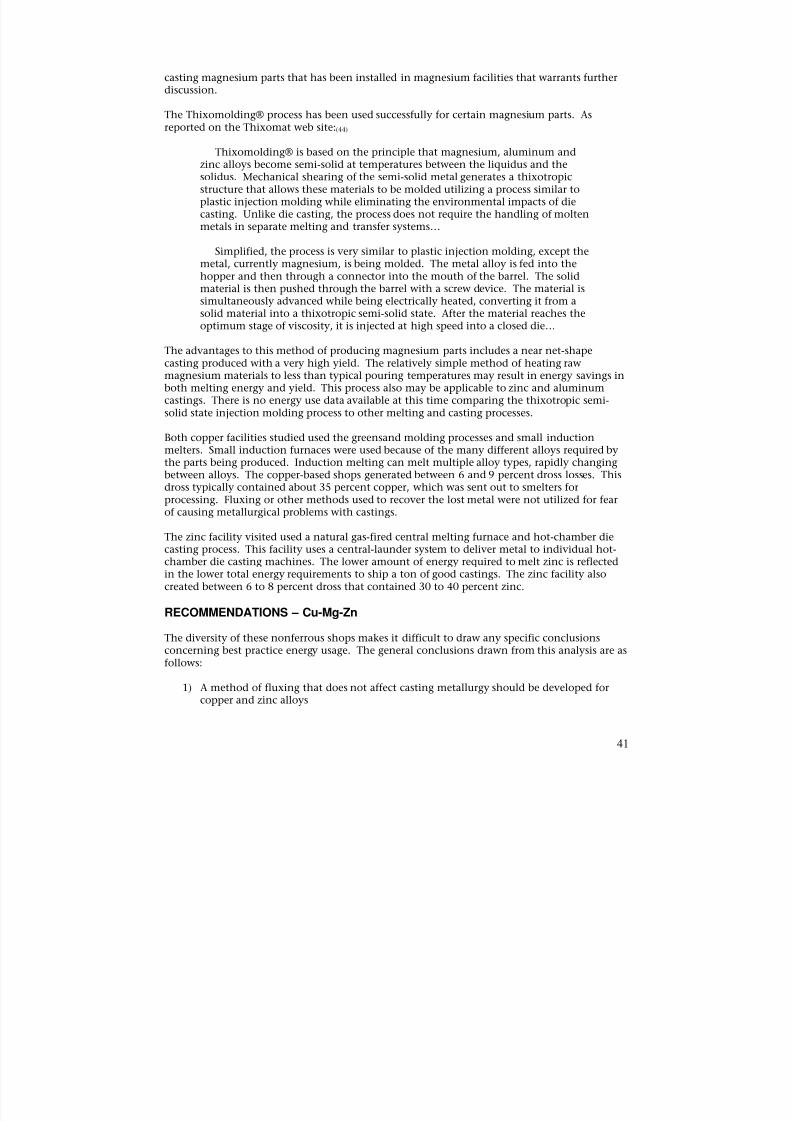
8/13/2019 Doebestpractice Casting
http://slidepdf.com/reader/full/doebestpractice-casting 42/116

8/13/2019 Doebestpractice Casting
http://slidepdf.com/reader/full/doebestpractice-casting 43/116
2) The overall energy consumption level is primarily affected by the alloy melt energy.3) Melting practice changes and yield improvements offer benefits in both reduced energy
consumption and operating costs.4) The thixotropic semi-solid state injection molding process needs to be evaluated to
determine its energy savings potential for magnesium and other metals such as zinc andaluminum.
RECOMMENDATIONS – FERROUS AND NONFERROUS
The documents reviewed and interviews conducted to obtain information for this study alsoyielded some work practice recommendations, that will assist foundries in reducing energyconsumption. The following are some general recommendations that apply to both ferrousand nonferrous melting:
1) Use clean scrap – one pound of sand charged means two pounds of iron or steel not meltedand increases the slag generated.
2) Maintain minimum tapping temperatures that ensure quality castings.3) Optimized scheduling – minimizes excessive holding power.
4) Proper Maintenance – reduced downtime on furnace saves energy.5) Keep lids tight to reduce energy losses.6) Refractory – maintain refractory thickness to factory recommendations.7) Eliminate hot spots – many foundries perform infrared inspections to determine electrical
problems and refractory problems prior to failures.8) Streamline temperature measurement – automated furnace temperature and power controls
will prevent overshooting temperature settings.
These work practice energy savings suggestions also were taken from the “Metal MeltingEfficiency Project,” CCMA, Technikon, 2001(23) and “How Your Induction Melt Shop CanSurvive the Energy Crisis,” Inductotherm, 2001(20).
42
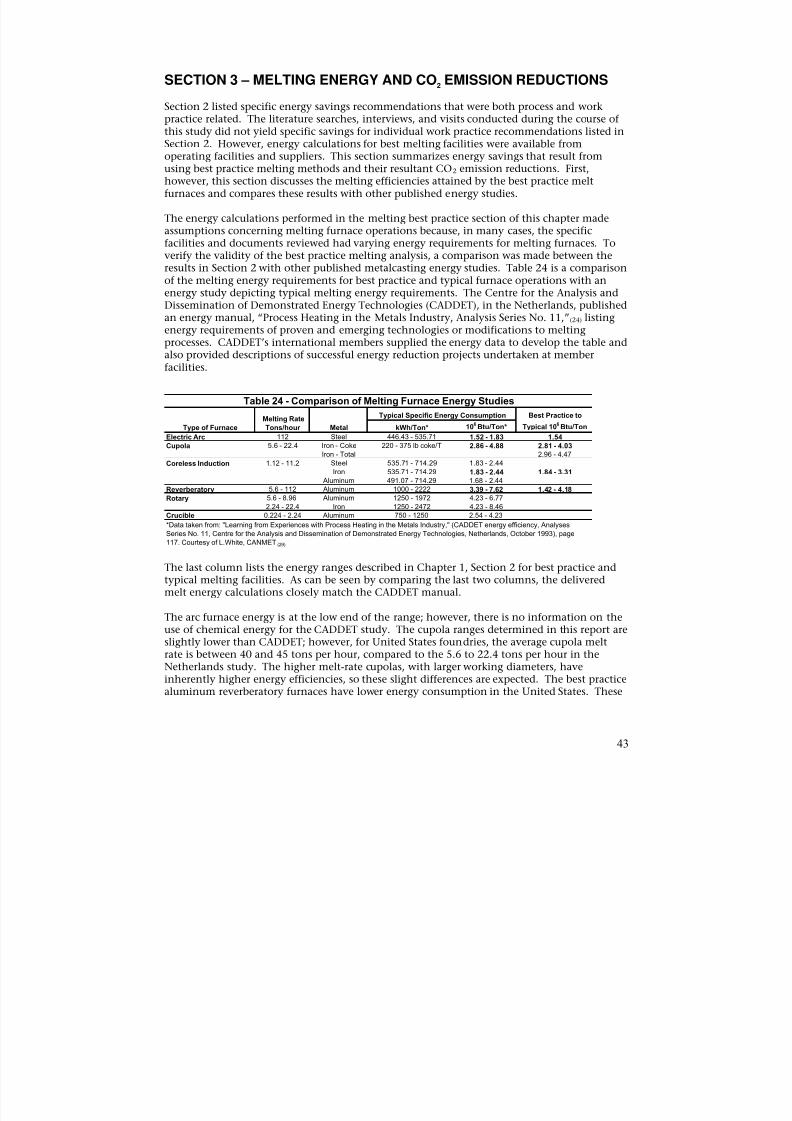
8/13/2019 Doebestpractice Casting
http://slidepdf.com/reader/full/doebestpractice-casting 44/116
SECTION 3 – MELTING ENERGY AND CO2 EMISSION REDUCTIONS
Section 2 listed specific energy savings recommendations that were both process and workpractice related. The literature searches, interviews, and visits conducted during the course ofthis study did not yield specific savings for individual work practice recommendations listed inSection 2. However, energy calculations for best melting facilities were available fromoperating facilities and suppliers. This section summarizes energy savings that result fromusing best practice melting methods and their resultant CO2 emission reductions. First,however, this section discusses the melting efficiencies attained by the best practice meltfurnaces and compares these results with other published energy studies.
The energy calculations performed in the melting best practice section of this chapter madeassumptions concerning melting furnace operations because, in many cases, the specificfacilities and documents reviewed had varying energy requirements for melting furnaces. Toverify the validity of the best practice melting analysis, a comparison was made between theresults in Section 2 with other published metalcasting energy studies. Table 24 is a comparisonof the melting energy requirements for best practice and typical furnace operations with anenergy study depicting typical melting energy requirements. The Centre for the Analysis and
Dissemination of Demonstrated Energy Technologies (CADDET), in the Netherlands, publishedan energy manual, “Process Heating in the Metals Industry, Analysis Series No. 11,”(24) listingenergy requirements of proven and emerging technologies or modifications to meltingprocesses. CADDET’s international members supplied the energy data to develop the table andalso provided descriptions of successful energy reduction projects undertaken at memberfacilities.
Table 24 - Comparison of Melting Furnace Energy Studies
Type of Furnace
Melting Rate
Tons/hour Metal
Typical Specific Energy Consumption Best Practice to
Typical 106Btu/TonkWh/Ton* 10
6Btu/Ton*
Electric Arc 112 Steel 446.43 - 535.71 1.52 - 1.83 1.54
Cupola 5.6 - 22.4 Iron - Coke
Iron - Total
220 - 375 lb coke/T 2.86 - 4.88 2.81 - 4.03
2.96 - 4.47Coreless Induction 1.12 - 11.2 Steel 535.71 - 714.29 1.83 - 2.44
Iron 535.71 - 714.29 1.83 - 2.44 1.84 - 3.31 Aluminum 491.07 - 714.29 1.68 - 2.44
Reverberatory
Rotary
5.6 - 112
5.6 - 8.96
2.24 - 22.4
Aluminum
Aluminum
Iron
1000 - 2222
1250 - 1972
1250 - 2472
3.39 - 7.624.23 - 6.77
4.23 - 8.46
1.42 - 4.18
Crucible 0.224 - 2.24 Aluminum 750 - 1250 2.54 - 4.23
*Data taken from: "Learning from Experiences with Process Heating in the Metals Industry," (CADDET energy efficiency, Analyses
Series No. 11, Centre for the Analysis and Dissemination of Demonstrated Energy Technologies, Netherlands, October 1993), page
117. Courtesy of L.White, CANMET (29)
The last column lists the energy ranges described in Chapter 1, Section 2 for best practice andtypical melting facilities. As can be seen by comparing the last two columns, the deliveredmelt energy calculations closely match the CADDET manual.
The arc furnace energy is at the low end of the range; however, there is no information on theuse of chemical energy for the CADDET study. The cupola ranges determined in this report areslightly lower than CADDET; however, for United States foundries, the average cupola meltrate is between 40 and 45 tons per hour, compared to the 5.6 to 22.4 tons per hour in theNetherlands study. The higher melt-rate cupolas, with larger working diameters, haveinherently higher energy efficiencies, so these slight differences are expected. The best practicealuminum reverberatory furnaces have lower energy consumption in the United States. These
43
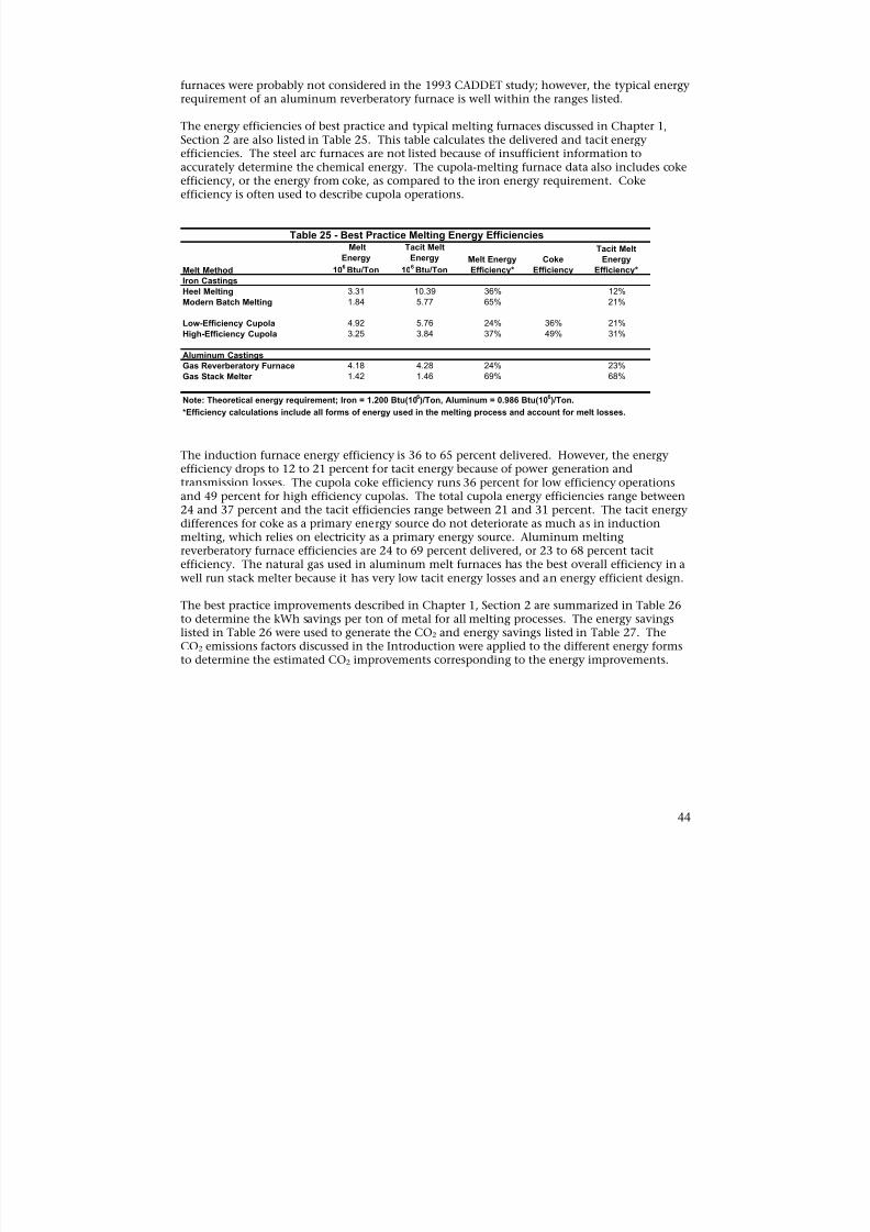
8/13/2019 Doebestpractice Casting
http://slidepdf.com/reader/full/doebestpractice-casting 45/116
furnaces were probably not considered in the 1993 CADDET study; however, the typical energyrequirement of an aluminum reverberatory furnace is well within the ranges listed.
The energy efficiencies of best practice and typical melting furnaces discussed in Chapter 1,Section 2 are also listed in Table 25. This table calculates the delivered and tacit energyefficiencies. The steel arc furnaces are not listed because of insufficient information to
accurately determine the chemical energy. The cupola-melting furnace data also includes cokeefficiency, or the energy from coke, as compared to the iron energy requirement. Cokeefficiency is often used to describe cupola operations.
Table 25 - Best Practice Melting Energy EfficienciesMelt Tacit Melt Tacit Melt
Energy Energy Melt Energy Coke Energy
Melt Method 106 Btu/Ton 106 Btu/Ton Efficiency* Efficiency Efficiency*
Iron Castings
Heel Melting 3.31 10.39 36% 12%
Modern Batch Melting 1.84 5.77 65% 21%
Low-Efficiency Cupola 4.92 5.76 24% 36% 21%
High-Efficiency Cupola 3.25 3.84 37% 49% 31%
Aluminum Castings Gas Reverberatory Furnace 4.18 4.28 24% 23% Gas Stack Melter 1.42 1.46 69% 68% Note: Theoretical energy requirement; Iron = 1.200 Btu(106)/Ton, Aluminum = 0.986 Btu(106)/Ton. *Efficiency calculations include all forms of energy used in the melting process and account for melt losses.
The induction furnace energy efficiency is 36 to 65 percent delivered. However, the energyefficiency drops to 12 to 21 percent for tacit energy because of power generation andtransmission losses. The cupola coke efficiency runs 36 percent for low efficiency operations
and 49 percent for high efficiency cupolas. The total cupola energy efficiencies range between24 and 37 percent and the tacit efficiencies range between 21 and 31 percent. The tacit energydifferences for coke as a primary energy source do not deteriorate as much as in inductionmelting, which relies on electricity as a primary energy source. Aluminum meltingreverberatory furnace efficiencies are 24 to 69 percent delivered, or 23 to 68 percent tacitefficiency. The natural gas used in aluminum melt furnaces has the best overall efficiency in awell run stack melter because it has very low tacit energy losses and an energy efficient design.
The best practice improvements described in Chapter 1, Section 2 are summarized in Table 26to determine the kWh savings per ton of metal for all melting processes. The energy savingslisted in Table 26 were used to generate the CO2 and energy savings listed in Table 27. TheCO2 emissions factors discussed in the Introduction were applied to the different energy formsto determine the estimated CO2 improvements corresponding to the energy improvements.
44
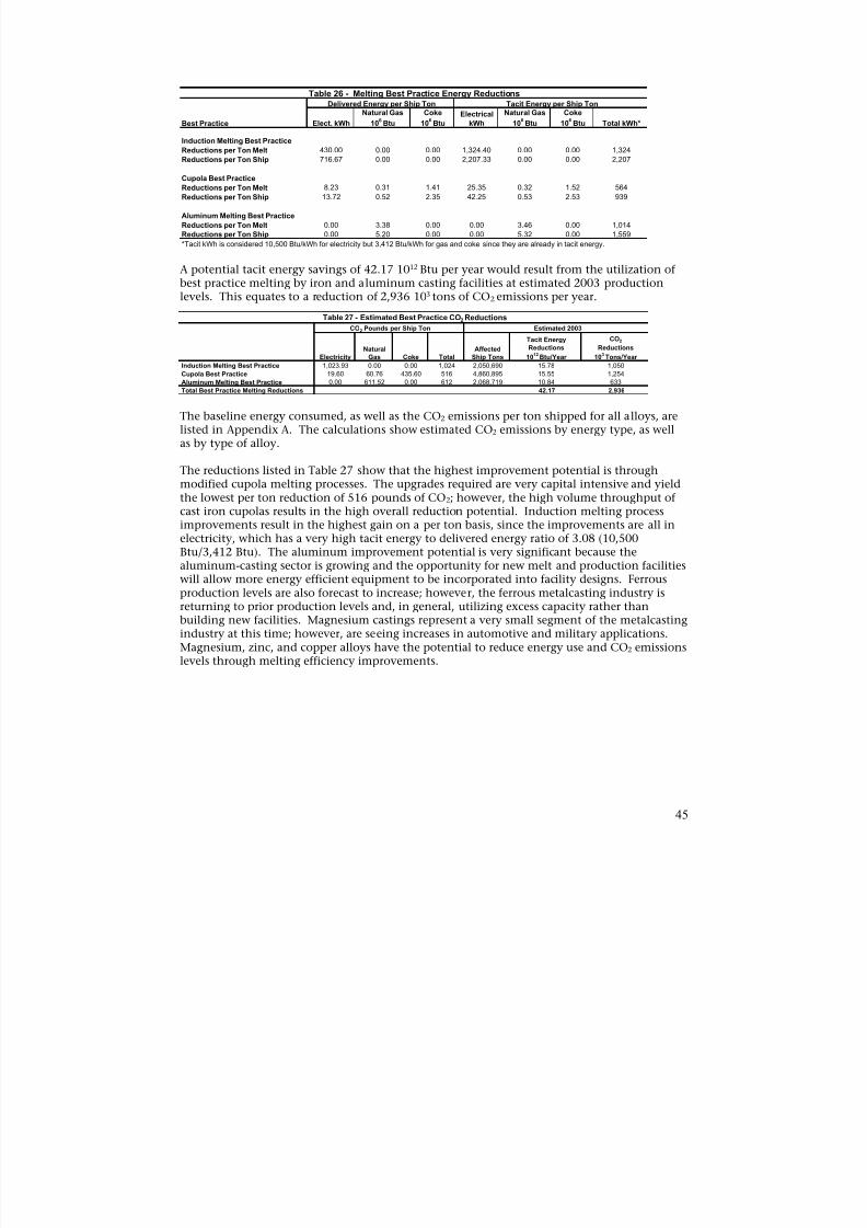
8/13/2019 Doebestpractice Casting
http://slidepdf.com/reader/full/doebestpractice-casting 46/116
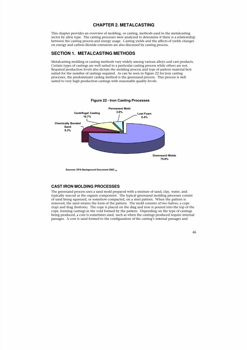
8/13/2019 Doebestpractice Casting
http://slidepdf.com/reader/full/doebestpractice-casting 47/116
CHAPTER 2. METALCASTING
This chapter provides an overview of molding, or casting, methods used in the metalcastingsector by alloy type. The casting processes were analyzed to determine if there is a relationshipbetween the casting process and energy usage. Casting yields and the affects of yields changeson energy and carbon dioxide emissions are also discussed by casting process.
SECTION 1. METALCASTING METHODS
Metalcasting molding or casting methods vary widely among various alloys and cast products.Certain types of castings are well suited to a particular casting process while others are not.Required production levels also dictate the molding process and type of pattern material bestsuited for the number of castings required. As can be seen in Figure 22 for iron castingprocesses, the predominant casting method is the greensand process. This process is wellsuited to very high production castings with reasonable quality levels.
Figure 22 - Iron Casting Processes
Permanent Mold
Centrifugal Casting
10.7%
3.8%Lost Foam
0.4%
Greensand Molds
Chemically Bonded
Sand
9.3%
75.8%
Sources: EPA Background Document 2002 (5)
CAST IRON MOLDING PROCESSES
The greensand process uses a sand mold prepared with a mixture of sand, clay, water, andtypically seacoal as the organic component. The typical greensand molding processes consistof sand being squeezed, or somehow compacted, on a steel pattern. When the pattern isremoved, the sand retains the form of the pattern. The mold consists of two halves, a cope(top) and drag (bottom). The cope is placed on the drag and iron is poured into the top of thecope, forming castings in the void formed by the pattern. Depending on the type of castingsbeing produced, a core is sometimes used, such as when the castings produced require internalpassages. A core is sand formed to the configuration of the casting’s internal passages and
46
8/13/2019 Doebestpractice Casting
http://slidepdf.com/reader/full/doebestpractice-casting 48/116
typically held together by some form of organic binder. The predominant core binder type is aphenolic urethane-based binder system.
Chemically-bonded sand molds are prepared by mixing sand with binders, similar to thoseused to make cores. The mold holds the shape of the pattern by hardening on the patternitself, due to the relatively fast reaction of the catalyst and the binder system. The molds are
then separated from the pattern and the two halves are put together to form a mold.Chemically-bonded molding is much slower than the greensand process. Chemically-bondedmolds may take several minutes or more to cure while a greensand-molding machine can makefive molds per minute. The chemically-bonded molding process, however, uses less expensivepattern materials and forms a more precise reproduction of the pattern, and therefore a higherquality part.
Centrifugal casting machines are used to make cast iron pipes and cylinder liners. They are notsuited to other types of parts. The machines are relatively simple, use no sand, and tend to bevery reliable. The configuration of the parts produced lends itself to a very efficient operation.Very small cores are sometimes used for certain types of pipe production. Other morespecialized processes are used for specific casting requirements and include permanent molds
and the lost foam process, which are also used for nonferrous alloys.
From an energy standpoint, the information analyzed for this study did not yield an advantagefor a specific casting method. The facility energy profiles used in this report and listed inAppendix A are all greensand facilities, except for the cast iron pipe facilities. The tacit energyconsumption of gray and ductile iron facilities was 29.7 106 Btu per ton shipped and 26.0 106
Btu per ton shipped, respectively. Literature searches did not yield any information on energydifferences in molding processes and considered molding process energy usage at between 6and 12 percent of total energy used in a metalcasting facility. Slight differences in moldingprocess energy requirements are not likely to affect the overall energy profile of the facility.Other issues, such as machine utilization and casting yield, will likely overshadow any castingprocess energy differences. For example, cast iron pipe facilities have very low tacit energy
consumption levels of 7.8 106
Btu per ton shipped. Cast iron pipe’s very high yield, relativelysimple and highly efficient centrifugal casting equipment, combined with no or very low coreusage, yields a very energy efficient operation.
STEEL MOLDING PROCESSES
Steel castings use processes more adapted to the requirements of the steel products. Figure 23shows the breakdown of steel casting processes. Steel casting production is evenly split amonggreensand, chemically-bonded, and permanent mold processes. The greensand process used bysteel facilities differs from iron in that it cannot use seacoal or a similar additive containingcarbon, which would cause problems with the lower carbon content of steel alloys. Thepermanent mold process used in steel is typically used to produce carbon steel railroad wheelsin graphite molds. Three steel facility energy profiles are described in Appendix A, with two
selected for this analysis. Both facilities used an electric melting process, one used arc and theother used induction. The tacit energy used per ton shipped was 40.70 106 Btu and 32.24 106
Btu, respectively. This is higher than the typical iron casting facility by about 33 percent. Thesteel metalcasters were much smaller than the iron facilities, which is typical of steel foundries.Steel production also requires heat treat operations, while finishing operations are very laborintensive compared to iron. One facility used chemically-bonded molds and the other used acombination of greensand and chemically-bonded processes. No conclusions can be drawnfrom the information reviewed for the molding processes. It appears that the smaller steel
47
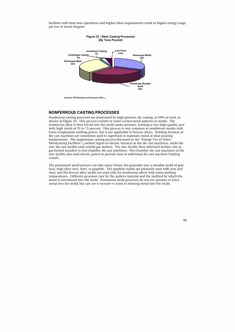
8/13/2019 Doebestpractice Casting
http://slidepdf.com/reader/full/doebestpractice-casting 49/116
facilities with heat treat operations and higher labor requirements result in higher energy usageper ton of metal shipped.
Figure 23 - Steel Casting Processes(By Tons Poured)
Investment Casting Lost Foam0.4%
Centrifugal Casting3%
Greensand Molds3% 32%
Permanent Mold32%
Chemically BondedSand
30%
Sources: EPA Background Document 2002 (5)
NONFERROUS CASTING PROCESSES
Nonferrous casting processes are dominated by high-pressure die casting, at 68% of total, asshown in Figure 24. This process consists of water-cooled metal patterns as molds. Thenonferrous alloy is then forced into the mold under pressure, forming a very high-quality partwith high yields of 70 to 75 percent. This process is very common to nonferrous metals withlower temperature melting points, but is not applicable to ferrous alloys. Holding furnaces at
die cast machines are sometimes used to superheat or maintain metal at ideal pouringtemperatures. The magnesium casting process discussed in the “Energy Use in SelectMetalcasting Facilities”(2) melted ingots in electric furnaces at the die cast machines, while thezinc die cast facility used central gas melters. The zinc facility then delivered molten zinc ingas-heated launders to hot-chamber die cast machines. Hot-chamber die cast machines at thezinc facility also used electric power to provide heat at individual die cast machine holdingvessels.
The permanent mold process can take many forms, but generally uses a reusable mold of grayiron, high-alloy iron, steel, or graphite. The graphite molds are primarily used with iron andsteel, and the ferrous alloy molds are used only for nonferrous alloys with lower meltingtemperatures. Different processes vary by the pattern material and the method by which the
metal is introduced into the mold. Permanent mold processes do not use pressure to forcemetal into the mold, but can use a vacuum to assist in drawing metal into the mold.
48
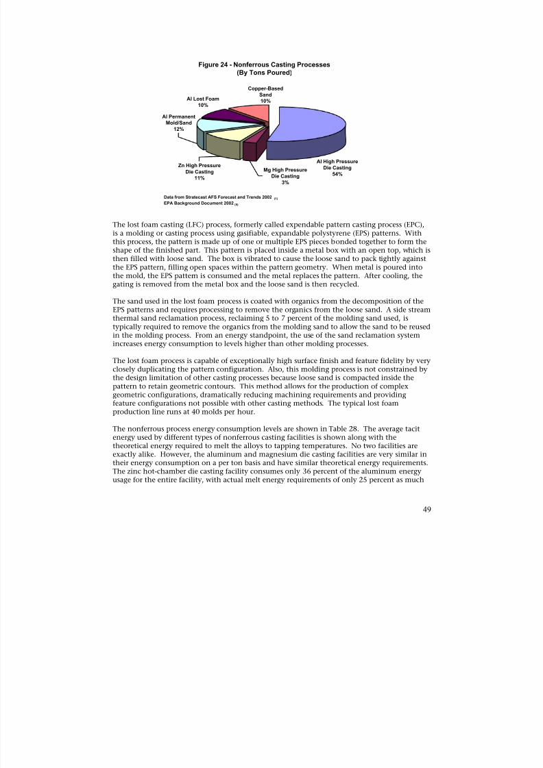
8/13/2019 Doebestpractice Casting
http://slidepdf.com/reader/full/doebestpractice-casting 50/116
Figure 24 - Nonferrous Casting Processes(By Tons Poured)
Copper-BasedSand
Al Lost Foam 10%
Al PermanentMold/Sand
12%
10%
Al High PressureZn High Pressure
Mg High Pressure Die CastingDie Casting
Die Casting 54%11%
3%
Data from Stratecast AFS Forecast and Trends 2002 (1) EPA Background Document 2002 (5)
The lost foam casting (LFC) process, formerly called expendable pattern casting process (EPC),is a molding or casting process using gasifiable, expandable polystyrene (EPS) patterns. Withthis process, the pattern is made up of one or multiple EPS pieces bonded together to form theshape of the finished part. This pattern is placed inside a metal box with an open top, which isthen filled with loose sand. The box is vibrated to cause the loose sand to pack tightly againstthe EPS pattern, filling open spaces within the pattern geometry. When metal is poured intothe mold, the EPS pattern is consumed and the metal replaces the pattern. After cooling, thegating is removed from the metal box and the loose sand is then recycled.
The sand used in the lost foam process is coated with organics from the decomposition of the
EPS patterns and requires processing to remove the organics from the loose sand. A side streamthermal sand reclamation process, reclaiming 5 to 7 percent of the molding sand used, istypically required to remove the organics from the molding sand to allow the sand to be reusedin the molding process. From an energy standpoint, the use of the sand reclamation systemincreases energy consumption to levels higher than other molding processes.
The lost foam process is capable of exceptionally high surface finish and feature fidelity by veryclosely duplicating the pattern configuration. Also, this molding process is not constrained bythe design limitation of other casting processes because loose sand is compacted inside thepattern to retain geometric contours. This method allows for the production of complexgeometric configurations, dramatically reducing machining requirements and providingfeature configurations not possible with other casting methods. The typical lost foam
production line runs at 40 molds per hour.
The nonferrous process energy consumption levels are shown in Table 28. The average tacitenergy used by different types of nonferrous casting facilities is shown along with thetheoretical energy required to melt the alloys to tapping temperatures. No two facilities areexactly alike. However, the aluminum and magnesium die casting facilities are very similar intheir energy consumption on a per ton basis and have similar theoretical energy requirements.The zinc hot-chamber die casting facility consumes only 36 percent of the aluminum energyusage for the entire facility, with actual melt energy requirements of only 25 percent as much
49
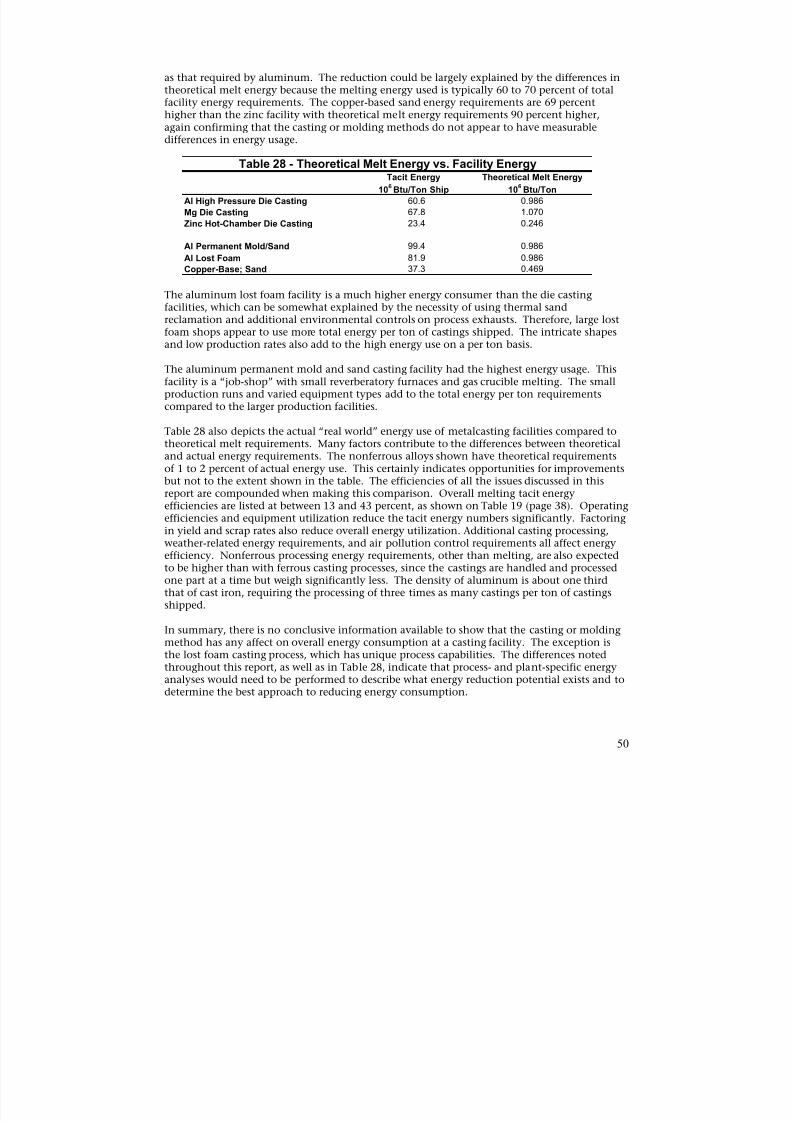
8/13/2019 Doebestpractice Casting
http://slidepdf.com/reader/full/doebestpractice-casting 51/116
as that required by aluminum. The reduction could be largely explained by the differences intheoretical melt energy because the melting energy used is typically 60 to 70 percent of totalfacility energy requirements. The copper-based sand energy requirements are 69 percenthigher than the zinc facility with theoretical melt energy requirements 90 percent higher,again confirming that the casting or molding methods do not appear to have measurabledifferences in energy usage.
Table 28 - Theoretical Melt Energy vs. Facility Energy
Al High Pressure Die Casting
Mg Die Casting
Zinc Hot-Chamber Die Casting
60.6
67.8
23.4
Tacit Energy
106 Btu/Ton Ship
0.986
1.070
0.246
Theoretical Melt Energy
106 Btu/Ton
Al Permanent Mold/Sand
Al Lost Foam
99.4
81.9
0.986
0.986
Copper-Base; Sand 37.3 0.469
The aluminum lost foam facility is a much higher energy consumer than the die castingfacilities, which can be somewhat explained by the necessity of using thermal sandreclamation and additional environmental controls on process exhausts. Therefore, large lostfoam shops appear to use more total energy per ton of castings shipped. The intricate shapesand low production rates also add to the high energy use on a per ton basis.
The aluminum permanent mold and sand casting facility had the highest energy usage. Thisfacility is a “job-shop” with small reverberatory furnaces and gas crucible melting. The smallproduction runs and varied equipment types add to the total energy per ton requirementscompared to the larger production facilities.
Table 28 also depicts the actual “real world” energy use of metalcasting facilities compared totheoretical melt requirements. Many factors contribute to the differences between theoretical
and actual energy requirements. The nonferrous alloys shown have theoretical requirementsof 1 to 2 percent of actual energy use. This certainly indicates opportunities for improvementsbut not to the extent shown in the table. The efficiencies of all the issues discussed in thisreport are compounded when making this comparison. Overall melting tacit energyefficiencies are listed at between 13 and 43 percent, as shown on Table 19 (page 38). Operatingefficiencies and equipment utilization reduce the tacit energy numbers significantly. Factoringin yield and scrap rates also reduce overall energy utilization. Additional casting processing,weather-related energy requirements, and air pollution control requirements all affect energyefficiency. Nonferrous processing energy requirements, other than melting, are also expectedto be higher than with ferrous casting processes, since the castings are handled and processedone part at a time but weigh significantly less. The density of aluminum is about one thirdthat of cast iron, requiring the processing of three times as many castings per ton of castings
shipped.
In summary, there is no conclusive information available to show that the casting or moldingmethod has any affect on overall energy consumption at a casting facility. The exception isthe lost foam casting process, which has unique process capabilities. The differences notedthroughout this report, as well as in Table 28, indicate that process- and plant-specific energyanalyses would need to be performed to describe what energy reduction potential exists and todetermine the best approach to reducing energy consumption.
50
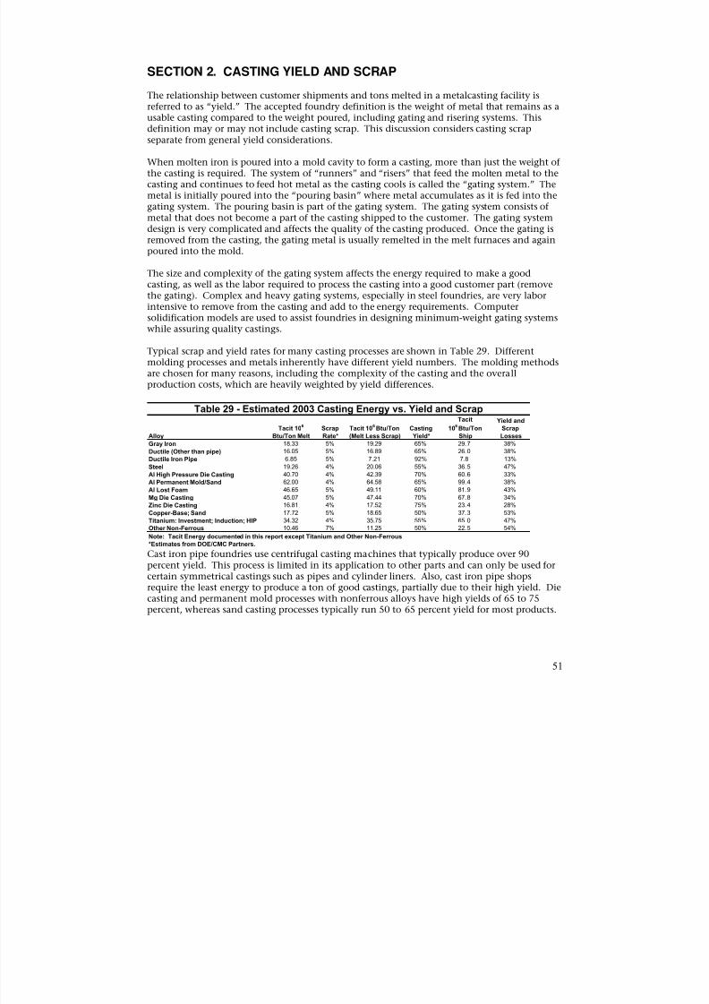
8/13/2019 Doebestpractice Casting
http://slidepdf.com/reader/full/doebestpractice-casting 52/116
SECTION 2. CASTING YIELD AND SCRAP
The relationship between customer shipments and tons melted in a metalcasting facility isreferred to as “yield.” The accepted foundry definition is the weight of metal that remains as ausable casting compared to the weight poured, including gating and risering systems. Thisdefinition may or may not include casting scrap. This discussion considers casting scrapseparate from general yield considerations.
When molten iron is poured into a mold cavity to form a casting, more than just the weight ofthe casting is required. The system of “runners” and “risers” that feed the molten metal to thecasting and continues to feed hot metal as the casting cools is called the “gating system.” Themetal is initially poured into the “pouring basin” where metal accumulates as it is fed into thegating system. The pouring basin is part of the gating system. The gating system consists ofmetal that does not become a part of the casting shipped to the customer. The gating systemdesign is very complicated and affects the quality of the casting produced. Once the gating isremoved from the casting, the gating metal is usually remelted in the melt furnaces and againpoured into the mold.
The size and complexity of the gating system affects the energy required to make a goodcasting, as well as the labor required to process the casting into a good customer part (removethe gating). Complex and heavy gating systems, especially in steel foundries, are very laborintensive to remove from the casting and add to the energy requirements. Computersolidification models are used to assist foundries in designing minimum-weight gating systemswhile assuring quality castings.
Typical scrap and yield rates for many casting processes are shown in Table 29. Differentmolding processes and metals inherently have different yield numbers. The molding methodsare chosen for many reasons, including the complexity of the casting and the overallproduction costs, which are heavily weighted by yield differences.
Table 29 - Estimated 2003 Casting Energy vs. Yield and ScrapTacit Yield and
Tacit 106 Scrap Tacit 106 Btu/Ton Casting 106 Btu/Ton Scrap
Alloy Btu/Ton Melt Rate* (Melt Less Scrap) Yield* Ship Losses
Gray Iron 18.33 5% 19.29 65% 29.7 38%
Ductile (Other than pipe) 16.05 5% 16.89 65% 26.0 38%
Ductile Iron Pipe 6.85 5% 7.21 92% 7.8 13%
Steel 19.26 4% 20.06 55% 36.5 47%
Al High Pressure Die Casting 40.70 4% 42.39 70% 60.6 33%
Al Permanent Mold/Sand 62.00 4% 64.58 65% 99.4 38%
Al Lost Foam 46.65 5% 49.11 60% 81.9 43%
Mg Die Casting 45.07 5% 47.44 70% 67.8 34%
Zinc Die Casting 16.81 4% 17.52 75% 23.4 28%
Copper-Base; Sand 17.72 5% 18.65 50% 37.3 53%
Titanium: Investment; Induction; HIP 34.32 4% 35.75 55% 65.0 47%
Other Non-Ferrous 10.46 7% 11.25 50% 22.5 54%
Note: Tacit Energy documented in this report except Titanium and Other Non-Ferrous
*Estimates from DOE/CMC Partners.
Cast iron pipe foundries use centrifugal casting machines that typically produce over 90percent yield. This process is limited in its application to other parts and can only be used forcertain symmetrical castings such as pipes and cylinder liners. Also, cast iron pipe shopsrequire the least energy to produce a ton of good castings, partially due to their high yield. Diecasting and permanent mold processes with nonferrous alloys have high yields of 65 to 75percent, whereas sand casting processes typically run 50 to 65 percent yield for most products.
51
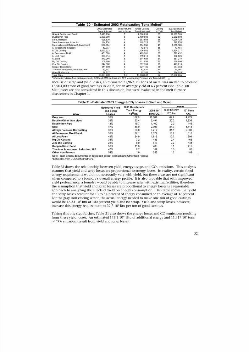
8/13/2019 Doebestpractice Casting
http://slidepdf.com/reader/full/doebestpractice-casting 53/116
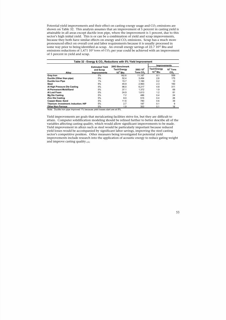
8/13/2019 Doebestpractice Casting
http://slidepdf.com/reader/full/doebestpractice-casting 54/116
Potential yield improvements and their effect on casting energy usage and CO2 emissions areshown on Table 32. This analysis assumes that an improvement of 5 percent in casting yield isattainable in all areas except ductile iron pipe, where the improvement is 1 percent, due to thissector’s high initial yield. This is or can be a combination of yield and scrap improvements,because they both have similar effects on energy and CO2 emissions. Scrap has a much more
pronounced effect on overall cost and labor requirements because it is usually processed insome way prior to being identified as scrap. An overall energy savings of 22.7 1012 Btu andemissions reductions of 1,471 103 tons of CO2 per year could be achieved with an improvementof 5 percent in yield and scrap.
Table 32 - Energy & CO2 Reductions with 5% Yield Improvement
ImprovementsEstimated Yield 2003 Benchmark
and Scrap Tacit Energy 2003 103 Tacit Energy 10
3Tons
1012
Btu CO2Alloy Improvements 1012
Btu Tons CO2
Gray Iron
Ductile (Other than pipe)
Ductile Iron Pipe
Steel
Al High Pressure Die CastingAl Permanent Mold/Sand
Al Lost Foam
Mg Die Casting
Zinc Die Casting
Copper-Base; Sand
Titanium: Investment; Induction; HIP
Other Non-Ferrous
5% 162.6 11,187 8.1 559
5% 52.4 3,494 2.6 175
1% 15.7 1,160 0.2 12
5% 45.9 2,993 2.3 150
5% 96.0 6,217 4.8 3115% 37.1 1,372 1.9 69
5% 24.9 1,613 1.2 81
5% 7.2 486 0.4 24
5% 8.0 515 0.4 26
5% 11.6 780 0.6 39
5% 2.7 187 0.1 9
5% 1.9 353 0.1 18
Note: Ductile iron pipe improved 1% because yield losses start are at 8%.
Yield improvements are goals that metalcasting facilities strive for, but they are difficult toattain. Computer solidification modeling should be refined further to better describe all of thevariables affecting casting quality, which would allow significant improvements to be made.Yield improvement in alloys such as steel would be particularly important because reduced
yield losses would be accompanied by significant labor savings, improving the steel castingsector’s competitive position. Other measures being investigated for potential yieldimprovements include research into the application of acoustic energy to reduce gating weightand improve casting quality.(45)
53

8/13/2019 Doebestpractice Casting
http://slidepdf.com/reader/full/doebestpractice-casting 55/116
SECTION 3 – CASTING ENERGY AND CO2 EMISSIONS REDUCTIONS
The metalcasting molding processes reviewed in Chapter 2, Section 1 did not indicate ameasurable difference in energy used per ton of casting shipped, except for the lost foamprocesses higher energy usage. The lost foam process has unique capabilities that can reducedownstream costs or allow for better product designs. Downstream costs such as machining
can be significantly reduced with the near, net shape parts produced. It also gives the castingdesigner more freedom to produce a part matching specific product needs, rather than meetingthe needs of traditional molding processes.
Generally, the energy differences among the facilities reviewed were the result of the type ofcasting produced, production volumes, or the type of alloy melted. The specific type of alloymelted generally influenced the total facility energy requirements on a per ton basis. Morespecifically, the amount of theoretical energy required to melt a certain alloy affects the totalenergy consumption of the facility. This indicates that in order to make significantimprovements in energy consumption levels, the melting methods and efficiencies are theprimary issues that must be addressed. Melting efficiencies also can be affected by moldingoperating efficiencies, as well as other issues within a metalcasting facility that prevent high
utilization of melting equipment.
The yield analysis in Chapter 2, Section 2 showed how process energy requirements could bereduced by improving yield. Many factors affect the specific types of molding process used,but in all cases designing a better gating system will improve relative yield numbers and reduceenergy requirements. In some cases, yield improvements will improve production capacitiesand reduce labor requirements in the finishing areas. This is a significant issue at smallerfacilities with lower volume production runs. The small shops tend to be very conservative intheir gating designs to ensure that small runs produce acceptable quality castings.
As shown in Table 32, yield improvements of 5 percent in all alloys, except for ductile ironpipe at 1 percent, result in tacit energy reductions of 22.7 1012 Btu and CO2 emissions
reductions of 1,471 103
tons per year at estimated 2003 metalcasting production levels.
54
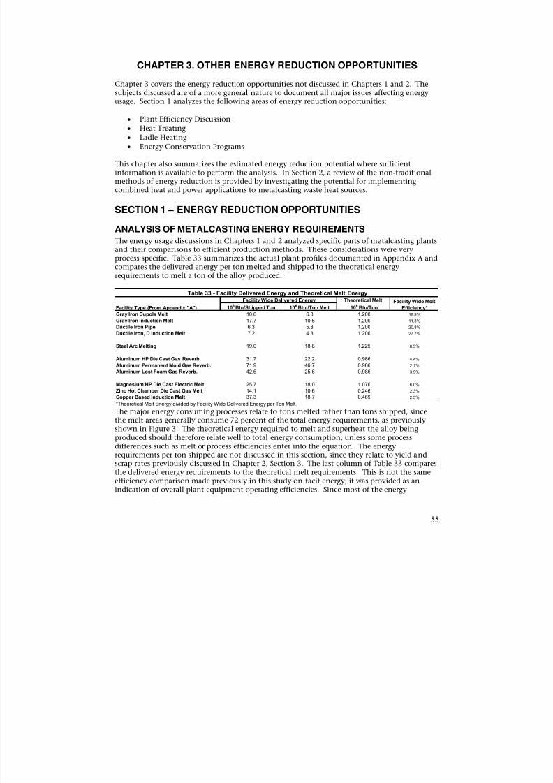
8/13/2019 Doebestpractice Casting
http://slidepdf.com/reader/full/doebestpractice-casting 56/116
CHAPTER 3. OTHER ENERGY REDUCTION OPPORTUNITIES
Chapter 3 covers the energy reduction opportunities not discussed in Chapters 1 and 2. Thesubjects discussed are of a more general nature to document all major issues affecting energyusage. Section 1 analyzes the following areas of energy reduction opportunities:
• Plant Efficiency Discussion
• Heat Treating
• Ladle Heating
• Energy Conservation Programs
This chapter also summarizes the estimated energy reduction potential where sufficientinformation is available to perform the analysis. In Section 2, a review of the non-traditionalmethods of energy reduction is provided by investigating the potential for implementingcombined heat and power applications to metalcasting waste heat sources.
SECTION 1 – ENERGY REDUCTION OPPORTUNITIES
ANALYSIS OF METALCASTING ENERGY REQUIREMENTS
The energy usage discussions in Chapters 1 and 2 analyzed specific parts of metalcasting plantsand their comparisons to efficient production methods. These considerations were veryprocess specific. Table 33 summarizes the actual plant profiles documented in Appendix A andcompares the delivered energy per ton melted and shipped to the theoretical energyrequirements to melt a ton of the alloy produced.
Table 33 - Facility Delivered Energy and Theoretical Melt Energy
Facility Type (From Appendix "A")
Facility Wide Delivered Energy Theoretical Melt
106
Btu/TonFacility Wide Melt
Efficiency*106
Btu/Shipped Ton 106Btu /Ton Melt
Gray Iron Cupola Melt 10.6 6.3 1.200 18.9%
Gray Iron Induction Melt 17.7 10.6 1.200 11.3%
Ductile Iron Pipe 6.3 5.8 1.200 20.8%
Ductile Iron, D Induction Melt 7.2 4.3 1.200 27.7%
Steel Arc Melting 19.0 18.8 1.225 6.5%
Aluminum HP Die Cast Gas Reverb. 31.7 22.2 0.986 4.4%
Aluminum Permanent Mold Gas Reverb. 71.9 46.7 0.986 2.1%
Aluminum Lost Foam Gas Reverb. 42.6 25.6 0.986 3.9%
Magnesium HP Die Cast Electric Melt 25.7 18.0 1.070 6.0%
Zinc Hot Chamber Die Cast Gas Melt 14.1 10.6 0.246 2.3%
Copper Based Induction Melt 37.3 18.7 0.469 2.5%
*Theoretical Melt Energy divided by Facility Wide Delivered Energy per Ton Melt.
The major energy consuming processes relate to tons melted rather than tons shipped, since
the melt areas generally consume 72 percent of the total energy requirements, as previouslyshown in Figure 3. The theoretical energy required to melt and superheat the alloy beingproduced should therefore relate well to total energy consumption, unless some processdifferences such as melt or process efficiencies enter into the equation. The energyrequirements per ton shipped are not discussed in this section, since they relate to yield andscrap rates previously discussed in Chapter 2, Section 3. The last column of Table 33 comparesthe delivered energy requirements to the theoretical melt requirements. This is not the sameefficiency comparison made previously in this study on tacit energy; it was provided as anindication of overall plant equipment operating efficiencies. Since most of the energy
55
8/13/2019 Doebestpractice Casting
http://slidepdf.com/reader/full/doebestpractice-casting 57/116
consumption is melt related, the comparison of theoretical melt energy requirements to actualdelivered energy is a general indicator of operating efficiencies (or utilization).
Since cast iron induction furnace melting requires less energy within a metalcasting facility,this melting method has the potential to have the lowest energy usage, but this is not alwaysthe case. The second column in Table 33 shows that the lowest per ton energy consuming
facility is the ductile induction facility at 4.3 106 Btu per ton melted, which is assumed to usethe latest heel melting furnace. The gray iron and ductile cupola shops have very similarenergy requirements, even though the ductile pipe shops must heat treat their castings. Thiswould indicate that the ductile iron pipe shops are melting more efficiently than the gray ironshops, which is to be expected because of their traditionally higher level of equipmentutilization. This issue is difficult to quantify, however, because of a lack of sufficient data todescribe plant operating efficiencies.
The gray iron induction melting facility used the older style heel melters, which are expectedto consume delivered energy similar to high efficiency cupola melting (Table 18). The actualdelivered energy consumed by the induction melting facility is 10.6 106 Btu per ton melted ascompared to 6.3 106 Btu per ton melted for the gray iron cupola shop. This induction furnace
shop was a much smaller facility than the cupola shop, as is typical of many induction furnaceoperations. The induction shop produced just over 13,000 tons of good castings per year,whereas the cupola shop produced in excess of 100,000 tons per year. This is an example ofthe energy differences typical of smaller facilities with older melting methods, and largercasting operations. The energy efficiency of a small facility would not be expected to approachthat of larger one; however, the efficiencies achieved by both sized facilities could likely beimproved. There is insufficient data to attempt to quantify the improvement potential.Furthermore, smaller facilities typically produce smaller production runs requiring differenttypes of molding and core make equipment; they also use smaller, less efficient meltingfacilities. These differences make direct comparisons difficult.
The steel casting facility listed has an energy consumption of 18.8 106 Btu per ton melted,
which is 77 percent higher than the gray iron induction facility just discussed. The steelmelting methods are better than the older induction melting processes, but steel also requiresheat treating operations and is very labor intensive because of the material produced. Also,steel facilities are typically small shops not able to take advantage of the efficiencies of largercasting plants.
The aluminum processes, listed in Table 33, bring up some interesting issues. The method ofmelting aluminum – using gas reverberatory furnaces – consumes large amounts of energy.The energy used by the average aluminum casting facility is 381 percent more per ton of metalmelted than iron facilities, although theoretically melting aluminum requires 18 percent lessenergy. The discussion on melting methods in Chapter 1, Section 2 showed that the averagealuminum casting facility required 25.73 106 Btu per ton melted, which could be reduced to20.94 106 Btu per ton through the use of more efficient gas melting furnaces. However, thisitself does not explain these significant differences. This change would still result in an energyconsumption of 310 percent more than cast iron on a per ton basis, which averaged 6.75 106
Btu per ton melted. Again, this percentage is based on delivered, not tacit energy.
Another factor considered is that two to three times as many aluminum parts must beproduced and processed to make up one ton of product as compared to ferrous alloys. This isoffset somewhat by the less energy intensive molding and processing methods. Publishedreports on aluminum facility energy use list the melting and holding processes at 77 percent of
56
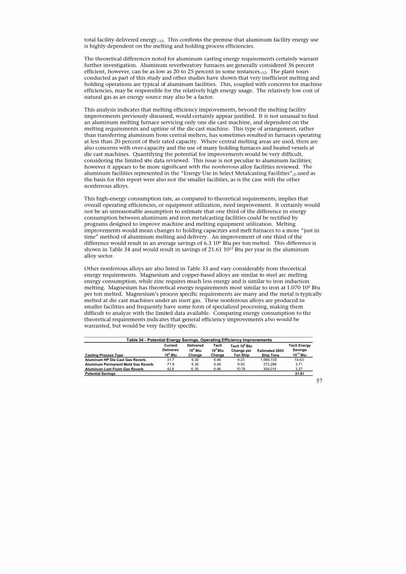
8/13/2019 Doebestpractice Casting
http://slidepdf.com/reader/full/doebestpractice-casting 58/116
total facility delivered energy.(12) This confirms the premise that aluminum facility energy useis highly dependent on the melting and holding process efficiencies.
The theoretical differences noted for aluminum casting energy requirements certainly warrantfurther investigation. Aluminum reverberatory furnaces are generally considered 36 percentefficient, however, can be as low as 20 to 25 percent in some instances.(12) The plant tours
conducted as part of this study and other studies have shown that very inefficient melting andholding operations are typical of aluminum facilities. This, coupled with concerns for machineefficiencies, may be responsible for the relatively high energy usage. The relatively low cost ofnatural gas as an energy source may also be a factor.
This analysis indicates that melting efficiency improvements, beyond the melting facilityimprovements previously discussed, would certainly appear justified. It is not unusual to findan aluminum melting furnace servicing only one die cast machine, and dependent on themelting requirements and uptime of the die cast machine. This type of arrangement, ratherthan transferring aluminum from central melters, has sometimes resulted in furnaces operatingat less than 20 percent of their rated capacity. Where central melting areas are used, there arealso concerns with over-capacity and the use of many holding furnaces and heated vessels at
die cast machines. Quantifying the potential for improvements would be very difficult,considering the limited site data reviewed. This issue is not peculiar to aluminum facilities;however it appears to be more significant with the nonferrous alloy facilities reviewed. Thealuminum facilities represented in the “Energy Use in Select Metalcasting Facilities”(2) used asthe basis for this report were also not the smaller facilities, as is the case with the othernonferrous alloys.
This high-energy consumption rate, as compared to theoretical requirements, implies thatoverall operating efficiencies, or equipment utilization, need improvement. It certainly wouldnot be an unreasonable assumption to estimate that one third of the difference in energyconsumption between aluminum and iron metalcasting facilities could be rectified byprograms designed to improve machine and melting equipment utilization. Melting
improvements would mean changes to holding capacities and melt furnaces to a more “just intime” method of aluminum melting and delivery. An improvement of one third of thedifference would result in an average savings of 6.3 106 Btu per ton melted. This difference isshown in Table 34 and would result in savings of 21.61 1012 Btu per year in the aluminumalloy sector.
Other nonferrous alloys are also listed in Table 33 and vary considerably from theoreticalenergy requirements. Magnesium and copper-based alloys are similar to steel arc meltingenergy consumption, while zinc requires much less energy and is similar to iron inductionmelting. Magnesium has theoretical energy requirements most similar to iron at 1.070 106 Btuper ton melted. Magnesium’s process specific requirements are many and the metal is typicallymelted at die cast machines under an inert gas. These nonferrous alloys are produced insmaller facilities and frequently have some form of specialized processing, making themdifficult to analyze with the limited data available. Comparing energy consumption to thetheoretical requirements indicates that general efficiency improvements also would bewarranted, but would be very facility specific.
Table 34 - Potential Energy Savings, Operating Efficiency ImprovementsCurrent Delivered Tacit Tacit 10
6Btu Tacit Energy
Delivered 106 Btu 10
6Btu Change per Estimated 2003 Savings
Casting Process Type 106 Btu Change Change Ton Ship Ship Tons 10
12Btu
Aluminum HP Die Cast Gas Reverb. 31.7 6.30 6.46 9.23 1,585,720 14.63
Aluminum Permanent Mold Gas Reverb. 71.9 6.30 6.46 9.93 373,266 3.71
Aluminum Lost Foam Gas Reverb. 42.6 6.30 6.46 10.76 304,014 3.27
Potential Savings 21.61
57
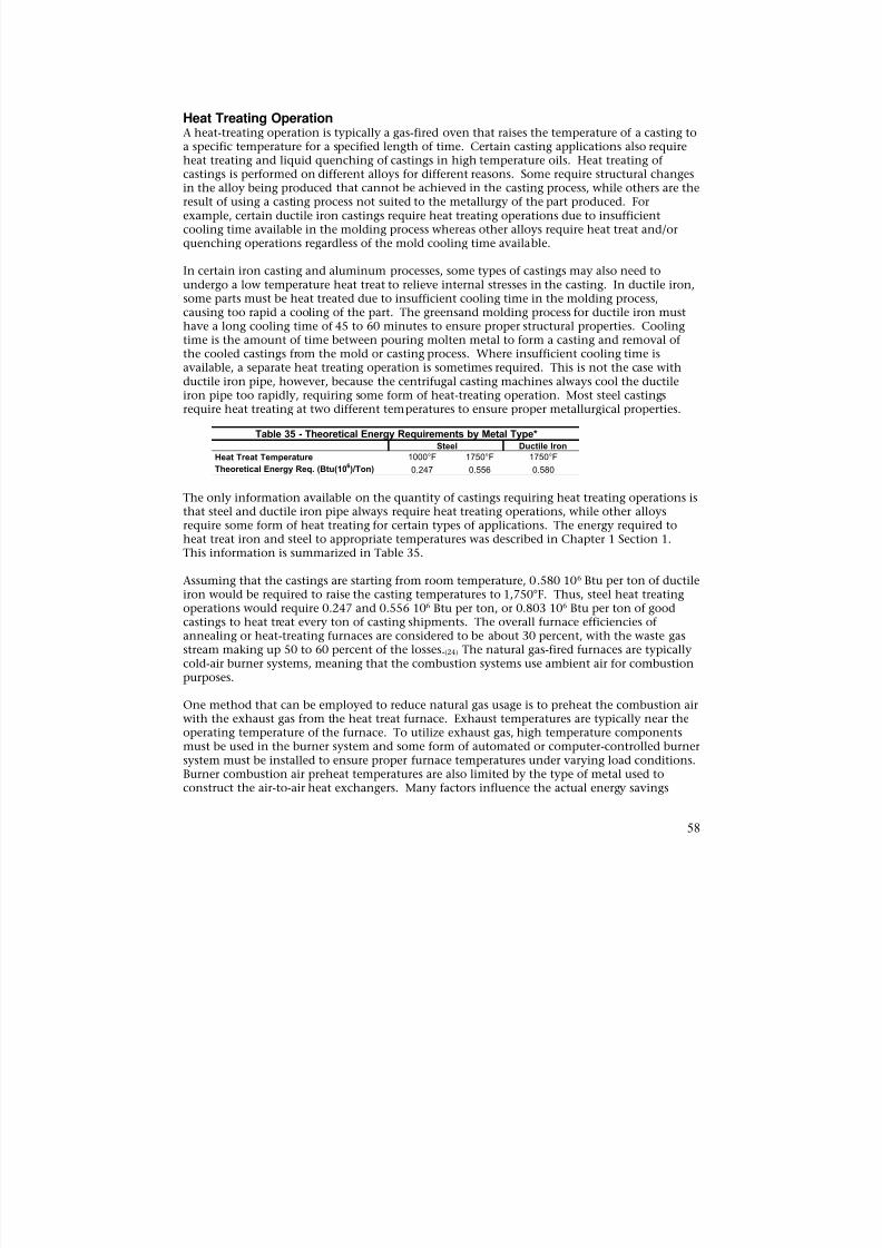
8/13/2019 Doebestpractice Casting
http://slidepdf.com/reader/full/doebestpractice-casting 59/116
Heat Treating OperationA heat-treating operation is typically a gas-fired oven that raises the temperature of a casting toa specific temperature for a specified length of time. Certain casting applications also requireheat treating and liquid quenching of castings in high temperature oils. Heat treating ofcastings is performed on different alloys for different reasons. Some require structural changesin the alloy being produced that cannot be achieved in the casting process, while others are theresult of using a casting process not suited to the metallurgy of the part produced. Forexample, certain ductile iron castings require heat treating operations due to insufficientcooling time available in the molding process whereas other alloys require heat treat and/orquenching operations regardless of the mold cooling time available.
In certain iron casting and aluminum processes, some types of castings may also need toundergo a low temperature heat treat to relieve internal stresses in the casting. In ductile iron,some parts must be heat treated due to insufficient cooling time in the molding process,causing too rapid a cooling of the part. The greensand molding process for ductile iron musthave a long cooling time of 45 to 60 minutes to ensure proper structural properties. Cooling
time is the amount of time between pouring molten metal to form a casting and removal ofthe cooled castings from the mold or casting process. Where insufficient cooling time isavailable, a separate heat treating operation is sometimes required. This is not the case withductile iron pipe, however, because the centrifugal casting machines always cool the ductileiron pipe too rapidly, requiring some form of heat-treating operation. Most steel castingsrequire heat treating at two different temperatures to ensure proper metallurgical properties.
Heat Treat Temperature 1000°F 1750°F 1750°F Theoretical Energy Req. (Btu(106)/Ton) 0.247 0.556 0.580
Ductile IronSteel
Table 35 - Theoretical Energy Requirements by Metal Type*
The only information available on the quantity of castings requiring heat treating operations isthat steel and ductile iron pipe always require heat treating operations, while other alloysrequire some form of heat treating for certain types of applications. The energy required toheat treat iron and steel to appropriate temperatures was described in Chapter 1 Section 1.This information is summarized in Table 35.
Assuming that the castings are starting from room temperature, 0.580 106 Btu per ton of ductileiron would be required to raise the casting temperatures to 1,750°F. Thus, steel heat treatingoperations would require 0.247 and 0.556 106 Btu per ton, or 0.803 106 Btu per ton of goodcastings to heat treat every ton of casting shipments. The overall furnace efficiencies ofannealing or heat-treating furnaces are considered to be about 30 percent, with the waste gasstream making up 50 to 60 percent of the losses.(24) The natural gas-fired furnaces are typicallycold-air burner systems, meaning that the combustion systems use ambient air for combustion
purposes.
One method that can be employed to reduce natural gas usage is to preheat the combustion airwith the exhaust gas from the heat treat furnace. Exhaust temperatures are typically near theoperating temperature of the furnace. To utilize exhaust gas, high temperature componentsmust be used in the burner system and some form of automated or computer-controlled burnersystem must be installed to ensure proper furnace temperatures under varying load conditions.Burner combustion air preheat temperatures are also limited by the type of metal used toconstruct the air-to-air heat exchangers. Many factors influence the actual energy savings
58
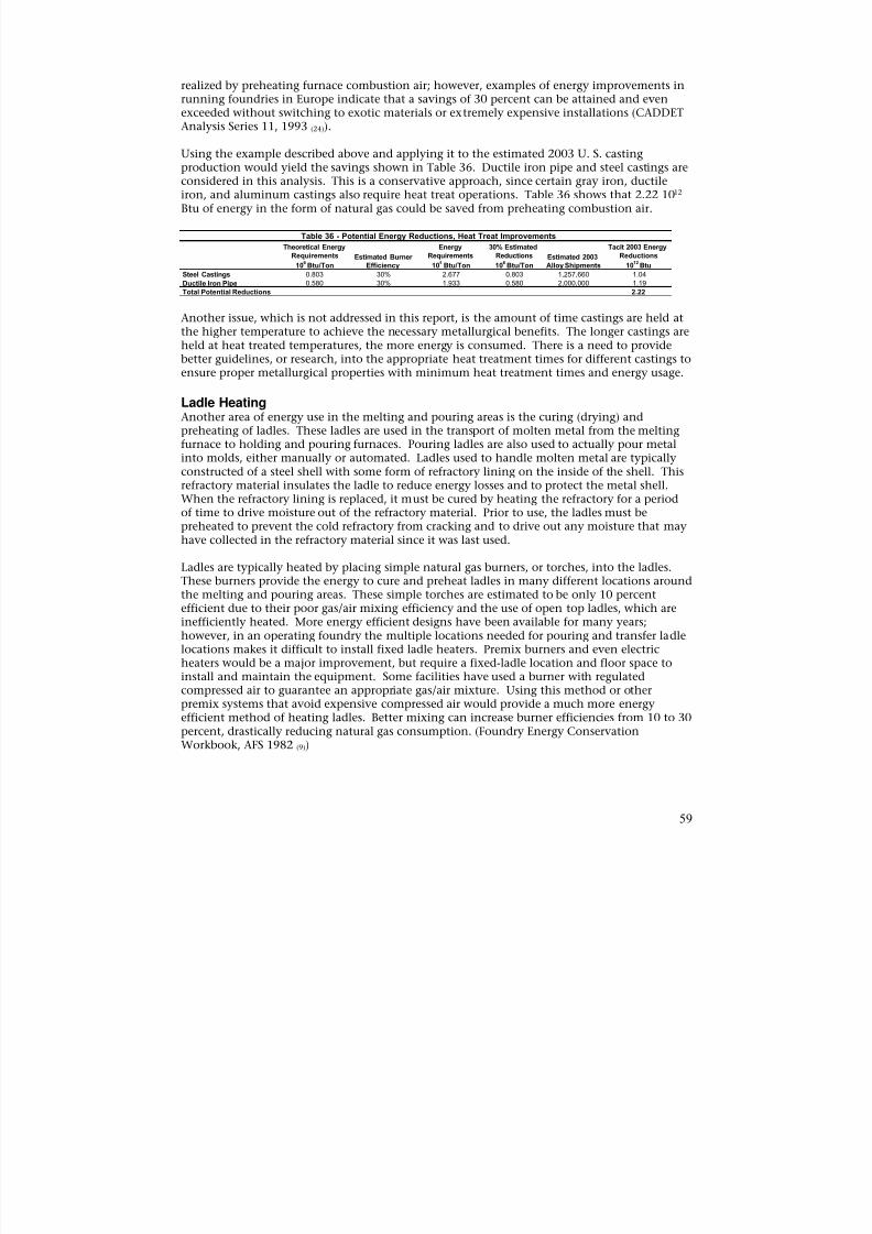
8/13/2019 Doebestpractice Casting
http://slidepdf.com/reader/full/doebestpractice-casting 60/116
realized by preheating furnace combustion air; however, examples of energy improvements inrunning foundries in Europe indicate that a savings of 30 percent can be attained and evenexceeded without switching to exotic materials or extremely expensive installations (CADDETAnalysis Series 11, 1993 (24)).
Using the example described above and applying it to the estimated 2003 U. S. casting
production would yield the savings shown in Table 36. Ductile iron pipe and steel castings areconsidered in this analysis. This is a conservative approach, since certain gray iron, ductileiron, and aluminum castings also require heat treat operations. Table 36 shows that 2.22 1012
Btu of energy in the form of natural gas could be saved from preheating combustion air.
Table 36 - Potential Energy Reductions, Heat Treat Improvements
Theoretical Energy Energy 30% Estimated Tacit 2003 EnergyRequirements Estimated Burner Requirements Reductions Estimated 2003 Reductions
106Btu/Ton Efficiency 10
6Btu/Ton 10
6Btu/Ton Alloy Shipments 10
12Btu
Steel Castings 0.803 30% 2.677 0.803 1,257,660 1.04
Ductile Iron Pipe 0.580 30% 1.933 0.580 2,000,000 1.19
Total Potential Reductions 2.22
Another issue, which is not addressed in this report, is the amount of time castings are held at
the higher temperature to achieve the necessary metallurgical benefits. The longer castings areheld at heat treated temperatures, the more energy is consumed. There is a need to providebetter guidelines, or research, into the appropriate heat treatment times for different castings toensure proper metallurgical properties with minimum heat treatment times and energy usage.
Ladle HeatingAnother area of energy use in the melting and pouring areas is the curing (drying) andpreheating of ladles. These ladles are used in the transport of molten metal from the meltingfurnace to holding and pouring furnaces. Pouring ladles are also used to actually pour metalinto molds, either manually or automated. Ladles used to handle molten metal are typicallyconstructed of a steel shell with some form of refractory lining on the inside of the shell. Thisrefractory material insulates the ladle to reduce energy losses and to protect the metal shell.
When the refractory lining is replaced, it must be cured by heating the refractory for a periodof time to drive moisture out of the refractory material. Prior to use, the ladles must bepreheated to prevent the cold refractory from cracking and to drive out any moisture that mayhave collected in the refractory material since it was last used.
Ladles are typically heated by placing simple natural gas burners, or torches, into the ladles.These burners provide the energy to cure and preheat ladles in many different locations aroundthe melting and pouring areas. These simple torches are estimated to be only 10 percentefficient due to their poor gas/air mixing efficiency and the use of open top ladles, which areinefficiently heated. More energy efficient designs have been available for many years;however, in an operating foundry the multiple locations needed for pouring and transfer ladlelocations makes it difficult to install fixed ladle heaters. Premix burners and even electric
heaters would be a major improvement, but require a fixed-ladle location and floor space toinstall and maintain the equipment. Some facilities have used a burner with regulatedcompressed air to guarantee an appropriate gas/air mixture. Using this method or otherpremix systems that avoid expensive compressed air would provide a much more energyefficient method of heating ladles. Better mixing can increase burner efficiencies from 10 to 30percent, drastically reducing natural gas consumption. (Foundry Energy ConservationWorkbook, AFS 1982 (9))
59
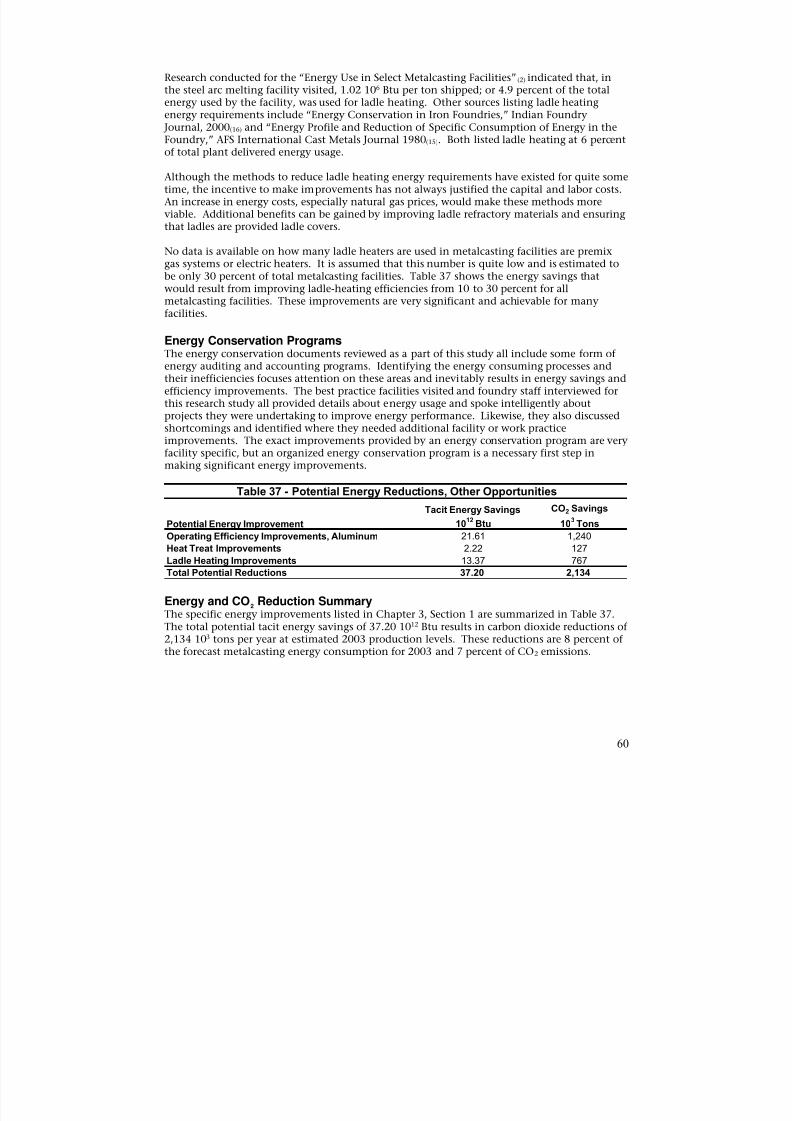
8/13/2019 Doebestpractice Casting
http://slidepdf.com/reader/full/doebestpractice-casting 61/116
Research conducted for the “Energy Use in Select Metalcasting Facilities”(2) indicated that, inthe steel arc melting facility visited, 1.02 106 Btu per ton shipped; or 4.9 percent of the totalenergy used by the facility, was used for ladle heating. Other sources listing ladle heatingenergy requirements include “Energy Conservation in Iron Foundries,” Indian Foundry Journal, 2000(16) and “Energy Profile and Reduction of Specific Consumption of Energy in theFoundry,” AFS International Cast Metals Journal 1980(15). Both listed ladle heating at 6 percent
of total plant delivered energy usage.
Although the methods to reduce ladle heating energy requirements have existed for quite sometime, the incentive to make improvements has not always justified the capital and labor costs.An increase in energy costs, especially natural gas prices, would make these methods moreviable. Additional benefits can be gained by improving ladle refractory materials and ensuringthat ladles are provided ladle covers.
No data is available on how many ladle heaters are used in metalcasting facilities are premixgas systems or electric heaters. It is assumed that this number is quite low and is estimated tobe only 30 percent of total metalcasting facilities. Table 37 shows the energy savings thatwould result from improving ladle-heating efficiencies from 10 to 30 percent for all
metalcasting facilities. These improvements are very significant and achievable for manyfacilities.
Energy Conservation ProgramsThe energy conservation documents reviewed as a part of this study all include some form ofenergy auditing and accounting programs. Identifying the energy consuming processes andtheir inefficiencies focuses attention on these areas and inevitably results in energy savings andefficiency improvements. The best practice facilities visited and foundry staff interviewed forthis research study all provided details about energy usage and spoke intelligently aboutprojects they were undertaking to improve energy performance. Likewise, they also discussedshortcomings and identified where they needed additional facility or work practiceimprovements. The exact improvements provided by an energy conservation program are very
facility specific, but an organized energy conservation program is a necessary first step inmaking significant energy improvements.
Table 37 - Potential Energy Reductions, Other Opportunities
Tacit Energy Savings CO2 Savings
Potential Energy Improvement 1012
Btu 103
Tons
Operating Efficiency Improvements, Aluminum 21.61 1,240
Heat Treat Improvements 2.22 127
Ladle Heating Improvements 13.37 767
Total Potential Reductions 37.20 2,134
Energy and CO2 Reduction SummaryThe specific energy improvements listed in Chapter 3, Section 1 are summarized in Table 37.The total potential tacit energy savings of 37.20 1012 Btu results in carbon dioxide reductions of2,134 103 tons per year at estimated 2003 production levels. These reductions are 8 percent ofthe forecast metalcasting energy consumption for 2003 and 7 percent of CO2 emissions.
60
8/13/2019 Doebestpractice Casting
http://slidepdf.com/reader/full/doebestpractice-casting 62/116
SECTION 2 – COMBINED HEAT AND POWER ANALYSIS
This section evaluates the potential for the application of combined heat and power (CHP) inthe metalcasting industry. CHP is the generation of electricity with the use of waste heatproduced during power generation to offset the need for purchased fuels such as natural gas orpropane. CHP is desirable because it can be economically beneficial under the rightconditions. It is also environmentally beneficial because the efficiency of a CHP system, withits use of waste heat, is much higher than the efficiency of a power plant. The greaterefficiency results in reduced air emissions and more effective use of natural resources.
Power generation without waste heat recovery, called onsite distributed generation, also canbe favorable when the cost of on-peak electricity is high relative to the cost of natural gas orother fuels used to operate the generator.
Metalcasting and foundry operations provide an opportunity to use purchased fuels for CHP, aswell as the thermal (heat) and/or chemical energy stored in the process waste streams togenerate electricity. Since the “waste” energy is essentially free, there is no additional fuel costincurred for equipment operation, although maintenance costs merit consideration. Examples
of electricity generation from waste energy are use of high quality (temperature) heat togenerate steam for driving a steam turbine, or use of lower grade waste heat (400°F to 500°F) todrive an Organic Rankine Cycle (ORC) turbogenerator .
To address the opportunities described above, the potential for the application of CHP and useof waste energy is evaluated using the following scenarios:
1. “Packaged” systems such as a microturbine or similar small-scale generation with wasteheat integrated into the process.
2. Fuel cells with waste heat integrated into the process.
3. Waste heat recovery to produce useful heat energy at a higher temperature using a heatpump.
4. Waste heat chillers or absorption heat pumps for heat recovery to provide cooling.
5. Trigeneration (i.e., combined cooling, heating and power).
6. Thermal (heat) and/or chemical energy stored in the process waste streams to generateelectricity.
The prime movers most suitable for CHP are those that provide waste heat at a high enoughtemperature to be useable the greatest amount of time. Five different prime movers were
considered for CHP use:
• Reciprocating engine
• Microturbine
• Stirling engine
• Organic Rankine Cycle turbogenerator
• Phosphoric acid fuel cell
61
8/13/2019 Doebestpractice Casting
http://slidepdf.com/reader/full/doebestpractice-casting 63/116
Each of these prime movers was evaluated assuming (1) an output of 500 kW, and (2) that allwaste heat generated was useable within a facility.
Onsite distributed generation (no heat recovery) was evaluated only for the microturbine andreciprocating engine, assuming an output of 500 kW. A generator output of 500 kW waschosen because it appears to be a small enough capacity to be suitable for use in most
foundries.
Use of Waste EnergyMany foundry operations produce hot exhaust streams that offer the potential for electricitygeneration through process heat recovery. While there may be many possibilities, four processoperations were selected as the most viable candidates for an initial screening:
• High efficiency cupola melting furnaces (cast iron)
• Aluminum stack melters• Steel casting heat-treat processes
• Ductile iron pipe heat-treat processes
The data used in all analyses represents, to the greatest extent possible, average values that arerepresentative of those that would be encountered in the field. Thus, the results are general innature and are intended to serve only as a guide to potential application.
Focus of EffortCandidates for electricity generation have been evaluated based on energy cost reduction only.There may be numerous reasons, other than energy cost benefit, for a facility to consider on-site power generation. These include the desire to lower air emissions to help protect theenvironment, and to improve the reliability of electric utility service, production rate, andsecurity. Thus, depending on circumstances surrounding a given facility, there may beadditional considerations. The other potential benefits, such as increases in production rate,are not quantified but are noted as appropriate.
Evaluation MethodologyWhen financial benefits are the overriding factor for consideration of power generation, thetwo most likely scenarios are generation without heat recovery (i.e., onsite distributedgeneration or DG) in order to reduce peak period costs, or the use of CHP. As discussedpreviously, with CHP, the waste heat from the generator (prime mover) is used to meet a heatduty otherwise served through purchased utilities such as natural gas. However, anotherpotential alternative is power generation with simultaneous heating and cooling, also calledtrigeneration. To produce cooling from a heat source, a thermally-activated absorption oradsorption chiller can be used. The foundry industry does not appear, however, to have asignificant need for refrigerated mechanical or thermal cooling, so this option may not beeconomically feasible on the basis of energy alone.
While refrigerated chilling may not be feasible on the basis of energy cost, there may be othereconomic benefits such as use of a low temperature source to improve production rates can beachieved by shortening the product-cooling period. Other benefits may be gained from havinga more constant temperature source available. While these may offer significant financial andenvironmental benefits, the focus of this study is on energy cost benefist only, so trigenerationand the related methods for thermal cooling (absorption chillers, waste heat chillers, etc.) willnot be considered further. However, since there may be instances where refrigerated cooling isused, information has been included for those who wish to consider this further.
62
8/13/2019 Doebestpractice Casting
http://slidepdf.com/reader/full/doebestpractice-casting 64/116
When DG is the selected option, the prime movers used will always require use of a purchasefuel like natural gas, fuel oil, or propane. This allows the generator to be started on demandduring the on-peak period when electrical costs are highest. A waste energy source is notnormally used to drive DG, although it is possible if the time availability of a waste energysource can be predicted.
Whether considering onsite distributed generation or CHP, the systems must be sized to meetbase load requirements. While this is important for onsite DG, it is particularly important forCHP. The reason for this is that CHP systems must meet both electric and thermal loadrequirements for as long a period as possible to optimize economic performance. Poorplanning and design with regard to thermal load matching can severely hamper the economicbenefits of CHP, lengthening the time frame for return on investment and potentially reducingthe likelihood that future energy cost reduction projects will be considered by management.
Quantitative Evaluation ApproachThe quantitative evaluations for CHP and onsite DG were initially to be carried out in partusing a screening tool developed by the Department of Energy (DOE). Review of the screening
tool, however, revealed that its use in the current context would be impractical given thenature of foundry operations; thus, the screening tool was not used. Instead, differentapproaches were selected for evaluation of CHP, DG, and energy recovery systems for powergeneration. These approaches are discussed below.
As noted earlier, proper thermal load matching is important to the success of any CHP system.For the purpose of this study, however, all waste heat generated by the prime mover is assumedto be useable during all times the generator is operating. To aid the reader in determiningapplicability, typical uses of the waste heat and temperatures are provided, based on the primemover used. Additionally, except when the “potential” to generate power is being evaluated(discussed later), generator output is limited to 500 kW from natural gas-fired prime movers(engines). This relatively low generator output helps to keep the analysis as practical as
possible with respect to matching the generator output to facility need.
Having stated that the generator output is a 500 kW natural gas-fired unit and that all wasteheat is used continuously, the economic performance of CHP and onsite DG can be fairlyeasily estimated. To allow prediction of financial benefit, the following assumptions wereapplied to the analysis:
• Natural gas is $6.63/106 Btu .
• Coke is $180/ton ($6.42/106 Btu).
• Electricity is $0.04475/kWh average.
• Electricity is $0.080/kWh during on-peak time.
• Operating hours based on a 16-hour day and 5-day work week, 50 weeks per year.(Since the processes under consideration may have widely varying operating hours atany given facility, benefits are shown based on 40 percent and 90 percent availabilityduring operating hours.)
63
8/13/2019 Doebestpractice Casting
http://slidepdf.com/reader/full/doebestpractice-casting 65/116
While it is always best to evaluate the financial performance of electricity generation on a netpresent value (NPV) basis, for simplicity, ROI is used with equipment and installation cost,based on rule of thumb estimates. Actual installation costs can vary widely and may makeup asignificant portion of the cost of any generation project. This implies that rule of thumbestimates, although experienced based, should be used for screening purposes only.
Evaluating the Potential for Power GenerationAs discussed previously, foundry processes present not only the opportunity to use purchasedfuels for electricity generation, but also the opportunity for electricity generation using thethermal and/or chemical energy stored in the process waste streams. An example of the use ofthermal energy is the heating of a cooler stream with a hot stream. This can be done directlyby mixing the hot and cold streams (more efficient) or indirectly (less efficient) with a heatexchanger.
An example of the use of the chemical energy stored in a waste stream is the combustion of
relatively cool (~500°F to 800 °F) cupola exhaust to create a very hot exhaust, which is thenused to pre-heat blast air. Combustion is possible due to the chemical energy contained in theconstituents of the cool cupola exhaust. Thus, blast air preheating improves overall cupola
efficiency because the heat supplied by the preheated blast air does not have to be supplied bypurchased fuels such as natural gas or coke. The operation of preheating blast air may be ofparticular interest to an energy manager who is trying to find ways to reduce facility costs. Themanager may ask “How efficient are we at using the waste energy from our processes? Isburning cupola exhaust to preheat blast air the best use of the energy in the exhaust?” Itwould be difficult, if not impossible, to extract all of the necessary information to make such adetermination from an equipment specification sheet. Thus, evaluation of waste energysources for their potential to perform work (e.g., generate electricity, drive a pump or fan)requires a different approach. The approach selected is based on the first and second laws ofthermodynamics, and is called “exergy” or “availability” analysis. The term exergy is used inthis report, but the two are equivalent.
Exergy analysis was selected because it provides a measure of the theoretical potential togenerate electricity from the waste energy sources available. The following sections provide abrief overview and demonstration of the use of exergy analysis and the insights that can beobtained with its application. A detailed explanation is beyond the scope of this report, butmore information can be found in the references (Kotas(33), Cengal(31)).
A Perspective on ExergyGenerally, most facility personnel and vendors use the term "energy" in a generic way withregard to quantity and use (e.g., Btu/hr, kW). What is often not fully taken into account is the“quality” of the energy source in question. As a result, it may go unnoticed that all Btus arenot equal in value, and the potential to perform work and minimize the impact of processoperation on the environment may be unrealized. For example, electricity that costs
$0.04475/kWh has an equivalent cost of approximately $13.11/106
Btu. This is approximatelytwice as much as natural gas at $6.63/106 Btu, on a Btu basis. This is because electricityrepresents “pure” exergy; it is completely available to perform work. Natural gas on the otherhand, must be converted, with all related inefficiency, before it can be used to perform work.Consider a fan requiring a 200-hp prime mover. The fan can be driven with either an electricmotor or a combustion turbine. A 200-hp electric motor is approximately 95 percent efficientwhereas the combustion turbine may be only 30 to 35 percent efficient, both on a second lawbasis. Thus, electricity has a greater value, due to its greater capacity to perform work.
64

8/13/2019 Doebestpractice Casting
http://slidepdf.com/reader/full/doebestpractice-casting 66/116

8/13/2019 Doebestpractice Casting
http://slidepdf.com/reader/full/doebestpractice-casting 67/116
∆φ (water)120°F →60°F = 59.91 – (519) x (0.1091) = 3.2871 Btu/lb
The natural gas requirement for water heating (Qf) is:
Qf = ∆h (water) = (3 gal/min x 60 min/hr x 8.34 lb/gal x 59.91 Btu/lb) ÷ 60% = 89,937 Btu/hr
Qf ÷ HHV = 89,937 Btu/hr ÷ 21,584 Btu/lb = 4.1668 lb natural gas /hr
The rate of change in exergy of the water as it flows into equilibrium with the dead state is:
∆φ (water)120°F →60°F = (3.2871 Btu/lb x 3 gal/min x 60 min/hr x 8.34 lb/gal) = 4,935 Btu/hr
The second law efficiency is:
ηII = (4,935 Btu/hr ÷ 89,937 Btu/hr) x 100 = 5.5%
The second law efficiency indicates the water heater is only about 5.5 percent efficient,compared to the first law efficiency of 60 percent. This means that of the work potential
contained in the chemical energy of the natural gas, only about 5.5 percent remains in the hotwater. An exergy balance around the hot water heater reveals that the exhaust containsexergy. However, the sum of the exergy of all output streams does not equal the exergy of theinput streams (natural gas). To the contrary, using the first law, the sum of the enthalpy of alloutput streams around the water heater will equal the heating value of the natural gas.
One may then ask “where did the work potential go?” It did not “go” anywhere. It was simplydestroyed through the process of combustion and heat exchange and cannot be recovered.Thus, making hot water from a high quality source like natural gas is a poor use of resourcesand is truly a very inefficient process.
PRIME MOVERS FOR COMBINED HEAT AND POWER AND ONSITE
DISTRIBUTION GENERATION
This section provides a brief overview of the different prime-mover technologies available todrive onsite distributed generation and CHP systems using purchased fuels. The followingoverview considers the prime movers currently available. Actual operating conditions maypose special limits to the application of a given prime mover.
Reciprocating EngineA Reciprocating engine uses an organic fuel, such as fuel oil, propane, biogas (digester orlandfill), or natural gas, which allows the possibility for fuel switching capability.Incorporating capability for fuel switching is a strategic move that permits a facility to operateon the least expensive fuel. Other concerns, however, such as environmental emissions, mayalso drive fuel choice.
Gaseous fuels may be preferable in most continuous use operations due to ease of transportand lower emissions. Fuel oils typically find greatest application for back-up generation. Low-
grade heat (~180°F to 240°F) is typically recovered from engine cooling water and exhaust foruse in CHP applications. Due to the lower temperature, the waste heat from reciprocatingengines may be most useful in metalcasting operations for preheating combustion air, make-upair, or other low temperature applications.
66
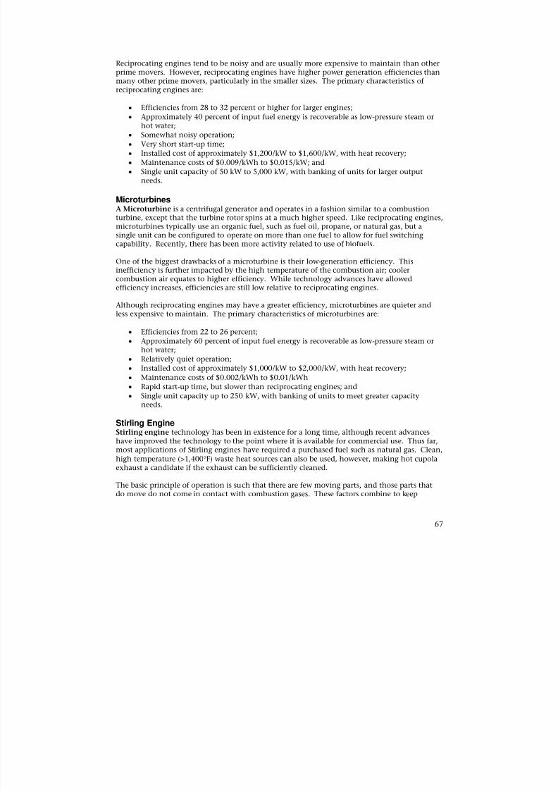
8/13/2019 Doebestpractice Casting
http://slidepdf.com/reader/full/doebestpractice-casting 68/116
Reciprocating engines tend to be noisy and are usually more expensive to maintain than otherprime movers. However, reciprocating engines have higher power generation efficiencies thanmany other prime movers, particularly in the smaller sizes. The primary characteristics ofreciprocating engines are:
• Efficiencies from 28 to 32 percent or higher for larger engines;• Approximately 40 percent of input fuel energy is recoverable as low-pressure steam or
hot water;• Somewhat noisy operation;
• Very short start-up time;
• Installed cost of approximately $1,200/kW to $1,600/kW, with heat recovery;
• Maintenance costs of $0.009/kWh to $0.015/kW; and
• Single unit capacity of 50 kW to 5,000 kW, with banking of units for larger outputneeds.
MicroturbinesA Microturbine is a centrifugal generator and operates in a fashion similar to a combustionturbine, except that the turbine rotor spins at a much higher speed. Like reciprocating engines,microturbines typically use an organic fuel, such as fuel oil, propane, or natural gas, but asingle unit can be configured to operate on more than one fuel to allow for fuel switchingcapability. Recently, there has been more activity related to use of biofuels.
One of the biggest drawbacks of a microturbine is their low-generation efficiency. Thisinefficiency is further impacted by the high temperature of the combustion air; coolercombustion air equates to higher efficiency. While technology advances have allowedefficiency increases, efficiencies are still low relative to reciprocating engines.
Although reciprocating engines may have a greater efficiency, microturbines are quieter andless expensive to maintain. The primary characteristics of microturbines are:
• Efficiencies from 22 to 26 percent;
• Approximately 60 percent of input fuel energy is recoverable as low-pressure steam orhot water;
• Relatively quiet operation;
• Installed cost of approximately $1,000/kW to $2,000/kW, with heat recovery;
• Maintenance costs of $0.002/kWh to $0.01/kWh• Rapid start-up time, but slower than reciprocating engines; and
• Single unit capacity up to 250 kW, with banking of units to meet greater capacityneeds.
Stirling EngineStirling engine technology has been in existence for a long time, although recent advanceshave improved the technology to the point where it is available for commercial use. Thus far,most applications of Stirling engines have required a purchased fuel such as natural gas. Clean,high temperature (>1,400°F) waste heat sources can also be used, however, making hot cupolaexhaust a candidate if the exhaust can be sufficiently cleaned.
The basic principle of operation is such that there are few moving parts, and those parts thatdo move do not come in contact with combustion gases. These factors combine to keep
67
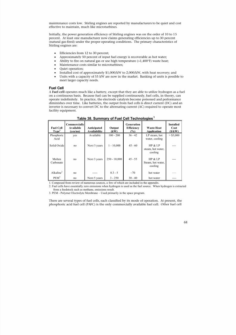
8/13/2019 Doebestpractice Casting
http://slidepdf.com/reader/full/doebestpractice-casting 69/116
maintenance costs low. Stirling engines are reported by manufacturers to be quiet and costeffective to maintain, much like microturbines.
Initially, the power generation efficiency of Stirling engines was on the order of 10 to 15percent. At least one manufacturer now claims generating efficiencies up to 30 percent(natural gas-fired) under the proper operating conditions. The primary characteristics of
Stirling engines are:
• Efficiencies from 12 to 30 percent;
• Approximately 50 percent of input fuel energy is recoverable as hot water;
• Ability to fire on natural gas or use high temperature (>1,400°F) waste heat;• Maintenance costs similar to microturbines;
• Quiet operation;
• Installed cost of approximately $1,000/kW to 2,000/kW, with heat recovery; and
• Units with a capacity of 55 kW are now in the market. Banking of units is possible tomeet larger capacity needs.
Fuel CellA Fuel cell operates much like a battery, except that they are able to utilize hydrogen as a fuelon a continuous basis. Because fuel can be supplied continuously, fuel cells, in theory, canoperate indefinitely. In practice, the electrode catalysts become poisoned and performancediminishes over time. Like batteries, the output from fuel cells is direct current (DC) and aninverter is necessary to convert DC to the alternating current (AC) required to operate mostfacility equipment.
Table 38. Summary of Fuel Cell Technologies1
Fuel Cell
Type1
Commercially
Available
(yes/no)
Anticipated
Availability
Output
(kW)
Generation
Efficiency
(%)
Waste Heat
Application
Installed
Cost
($/kW)
PhosphoricAcid
yes Available 100 - 200 36 - 42 LP steam, hotwater, cooling
> $5,000
Solid Oxide no Next 3 years 1 - 10,000 45 - 60 HP & LPsteam, hot water,
cooling
----
MoltenCarbonate
no Next 3 years 250 - 10,000 45 - 55 HP & LPSteam, hot water,
cooling
----
Alkaline2 no ----- 0.3 - 5 ~70 hot water ----
PEM3 no Next 5 years 3 - 250 30 - 40 hot water ----
1. Composed from review of numerous sources, a few of which are included in the appendix.2. Fuel cells have essentially zero emissions when hydrogen is used as the fuel source. When hydrogen is extracted
from a feedstock such as methane, emissions result.3. PEM - Polymer Electrolyte Membrane – Used primarily in the space program.
There are several types of fuel cells, each classified by its mode of operation. At present, thephosphoric acid fuel cell (PAFC) is the only commercially available fuel cell. Other fuel cell
68
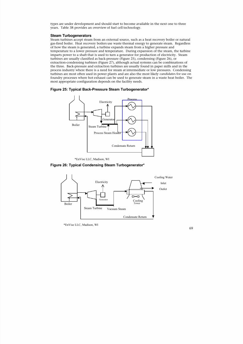
8/13/2019 Doebestpractice Casting
http://slidepdf.com/reader/full/doebestpractice-casting 70/116
types are under development and should start to become available in the next one to threeyears. Table 38 provides an overview of fuel cell technology.
Steam TurbogeneratorsSteam turbines accept steam from an external source, such as a heat recovery boiler or naturalgas-fired boiler. Heat recovery boilers use waste thermal energy to generate steam. Regardless
of how the steam is generated, a turbine expands steam from a higher pressure andtemperature to a lower pressure and temperature. During expansion of the steam, the turbineimparts power to a shaft that is used to turn a generator for production of electricity. Steamturbines are usually classified as back-pressure (Figure 25), condensing (Figure 26), orextraction-condensing turbines (Figure 27), although actual systems can be combinations ofthe three. Back-pressure and extraction turbines are usually found in paper mills and in theprocess industry where there is a need for steam at intermediate or low pressures. Condensingturbines are most often used in power plants and are also the most likely candidates for use onfoundry processes where hot exhaust can be used to generate steam in a waste heat boiler. Themost appropriate configuration depends on the facility needs.
Figure 25: Typical Back-Pressure Steam Turbogenerator*
BoilerSteam Turbine
ProcessElectricity
Generator
Process Steam Header
Condensate Return
*EnVise LLC, Madison, WI
Figure 26: Typical Condensing Steam Turbogenerator*
CoolingBoiler
Cooling Water
Inlet
Outlet
Condensate Return
Steam Turbine
Tower
Electricity
Generator
Vacuum Steam
*EnVise LLC, Madison, WI
69
8/13/2019 Doebestpractice Casting
http://slidepdf.com/reader/full/doebestpractice-casting 71/116
Steam turbogenerators represent a mature technology that can be very cost effective incombined heat and power applications. Condensing steam turbines are typically not costeffective unless the fuel source is free – as with waste heat – or very low cost. Examples wherecondensing turbines may be cost effective are in the use of waste heat boilers for steamgeneration using hot cupola exhaust.
Figure 27: Extraction-Condensing Steam Turbogenerator*
Boiler
Cooling Water
Inlet
Outlet
Condensate Return
Steam Turbine
Cooling
Tower
Electricity
Generator
MP Steam To Process
*EnVise LLC, Madison, WI
Determining the generation system (boiler, turbine, or generator) efficiency with a steamturbine is somewhat more complicated than for other prime movers. The second lawefficiency of the boiler is used, not the first law efficiency, as is reported in much of theliterature. (The first law efficiency is also the efficiency estimated from a boiler combustion
analysis.) For example, an optimized power plant boiler might have a first law efficiency (ηI) of
86 percent, but a second law efficiency (ηII) of only 43 percent. Steam turbines typically havesecond law (isentropic) efficiencies in the range of 38 to 80 percent, depending on a number of
factors like size, speed, and type (back-pressure, condensing, etc.). The electricity generatorcoupled to a steam turbine typically has a second law efficiency of 95 to 96 percent. Thisimplies that 95 to 96 percent of the shaft energy used to turn the generator is converted toelectricity. The second law generation efficiency can be determined simply by dividing theelectricity output in Btu/hr by the fuel energy input in Btu/hr. With this in mind, thefollowing is a summary of the primary characteristics of steam turbogenerators:
• Combined steam turbine/generator second law efficiencies range from about 35 to 77percent, depending on size, speed, and mode of operation. Smaller systems tend tohave lower efficiencies. Second law system efficiencies, which include the
turbine/generator and the boilers (ηII =43% for gas-fired), range from about 15 to 34percent. Cogeneration or trigeneration system efficiencies can be much higher.
• When heat is recovered from a backpressure turbine, it is usually recovered as low – tomedium – pressure steam or hot water.
• Relatively low maintenance costs of about $0.004/kWh.
• Relatively quiet operation.
70
8/13/2019 Doebestpractice Casting
http://slidepdf.com/reader/full/doebestpractice-casting 72/116
• Installed costs, excluding the boiler, typically range from $400/kW to $1,000/kWdepending on system size.
• Has single unit capacities of 50 kW to very large power plant turbines with capacitiesgreater than 100 MW (100,000 kW).
Organic Cycle Turbogenerator The Organic Rankine Cycle (ORC) turbogenerator operates in a cycle similar to thecondensing steam turbine shown in Figure 26. One of the fundamental differences is the useof a specialized fluorocarbon refrigerant instead of water as the working fluid. The propertiesof the refrigerant provide an advantage of the ORC over a steam cycle turbine. The ORC
turbogenerator can operate at a relatively low temperature (225°F to 500°F), making it suitablefor recovery of low-temperature waste heat for power production.
A disadvantage of the ORC turbogenarator is that its second law efficiency is somewhat lowerthan for the typical steam turbogenerator. Additionally, the field application of ORCturbogenerator technology is relatively new in comparison to steam turbine technology.However, the capabilities of the ORC allow its use in cases where a low temperature heat source
is readily available and steam turbines or other technologies are not applicable. The followingis a summary of the primary characteristics of ORC turbogenerators:
• System second law efficiencies, which include the turbine/generator and the heatsource, range from about 5 to 14 percent, depending on the application. Whenapplicable, cogeneration or trigeneration system efficiencies can be much higher.
• Approximately 50 percent of input fuel energy is recoverable as waste heat in the formof low-pressure steam or hot water.
• Information on maintenance cost were not readily available, but would be expected tobe similar to or less than a steam turbine cycle, given reports of reduced turbine blade
erosion. This is due to the use of the fluorocarbon refrigerant as a working fluid insteadof water.
• Relatively quiet operation.
• Installed equipment costs (without heat recovery) range from about $1,500/kW to$3,000/kW depending on system size.
• The net electrical output for single units from one manufacturer (Turboden) rangesfrom 450 kW to 1,500 kW.
WASTE HEAT RECOVERY OPPORTUNITIESBy definition, combined heat and power means the generation of power and use of the wasteheat produced by the generator to offset heat from purchased fuel. There are a variety of waysto recover and use waste heat. The following discussion provides some background on thepotential applications.
Recuperative Heat ExchangerA recuperative heat exchanger, or recuperator, is a more specific name for an exchangerdesigned for gas-to-gas heat transfer. Recuperators are very common in industry. An example
71
8/13/2019 Doebestpractice Casting
http://slidepdf.com/reader/full/doebestpractice-casting 73/116
is blast air preheating using hot cupola exhaust. Heat exchangers come in a variety of typesand materials, depending on the intended use.
The lower the design approach temperature, the more efficient the heat exchanger will be atperforming its intended function. However, lower approach temperatures require a greaterexchanger area, which increases cost. The optimized exchanger or exchanger network will be
the one balanced for performance and cost. Fouling, low flow rate, and corrosion can reducethe performance of heat exchangers, so it important that they be properly sized andmaintained just as other equipment.
Typically, recuperators used to preheat blast air are inefficient relative to heat transfer area.This is because the “dirty” cupola exhaust requires a larger spacing between tubes to preventplugging. The larger spacing implies lower heat exchanger area for a given size exchanger.
The efficiency of a heat exchanger is typically denoted by its “effectiveness.” Effectiveness isbased on the first law and is the ratio of the heat recovered to the heat available. Theeffectiveness of a typical recuperator is 60 to 70 percent. The effectiveness of a blast airpreheater is generally much lower. The higher the effectiveness of a recuperator, the greater
the recovery of heat and the more cost-effective the operation.
When considering energy cost reduction alternatives, it would be prudent to considerimproving the performance of existing systems through increases in heat transfer area. For
example, a facility that is presently realizing a hot blast air temperature of 1,000°F with the
existing preheater may be able to add exchanger area to increase the temperature to 1,200°F orgreater. This can offer numerous advantages in addition to energy cost reduction, includingbut not limited to:
• Equipment redundancy, which requires no additional maintenance skills.
• Potential ease and relatively low cost of installation.
• Potential reduction in the oxidation of product, which can result from lower blast airtemperature.
Thermal ChillerAbsorption and adsorption chillers are types of thermally activated chillers. While absorptionand adsorption chillers differ in the sorbent used, they both provide a net cooling effect givenheat input. As previously noted, there appears to be minimal need for refrigerated cooling infoundry and metalcasting operations and such options are not specifically covered in thisreport. Some potential applications are office air conditioning, sand cooling, anddehumidification of cupola hot blast air. For informational purposes, a brief summary ofabsorption and adsorption chillers is provided.
Absorption ChillersSeveral types of absorption chillers are currently available, including:
• Indirect-fired, single-effect absorption;
• Indirect-fired, double-effect absorption; and
• Direct-fired, double-effect absorption.
72
8/13/2019 Doebestpractice Casting
http://slidepdf.com/reader/full/doebestpractice-casting 74/116
An indirectly-fired absorption chiller operates on hot water or steam. A direct-fired unittypically requires combustion of natural gas.
Single-effect absorption chillers use a single stage for regeneration of lithium bromide salt withwater as a refrigerant, although ammonia is also used. Double-effect units use an additionalgenerator, condenser, and heat exchanger for greater heat recovery. Using the coefficient of
performance (COP), double-effect chillers can be up to 40 percent more efficient than single-effect chillers; however, the cost is also 30 to 50 percent higher. A summary of some of thecharacteristics of absorption chillers is provided in Table 39.
Adsorption ChillersAdsorption chillers have been used primarily in Europe and Japan, but appear to be gainingacceptance in the United States. Adsorption chillers operate in a manner similar to that ofabsorption chillers, except that the sorbent is silica gel rather than lithium bromide. The silicagel is reported by one manufacturer to be non-corrosive and to require changing far lessfrequently than absorption chillers. The use of sorbent appears to make a significant differencein life-cycle costs, with the adsorption chiller being the most cost effective. A summary of thecharacteristics of adsorption chillers is provided in Table 39. This information is a compilation
of data from numerous sources, a few of which are included in the appendix (Ryan(38),Trane(39)).
Table 39. Summary of Absorption and Adsorption Chiller Characteristics
Criteria
Single-effect
Absorption
Double-effect
Absorption Adsorption
Coefficient of Performance(Btu/hr-output/Btu/hr-input)
Salt UsedCapacity (ton)
Installed Cost ($/ton)Maintenance Cost ($/ton) 3
0.5 to 0.7
Lithium Bromide1
380 to 1,650
$400 to $600$20 to $35
~1
Lithium Bromide1
380 to 1,650
$600 to $800$20 to $35
0.4 to 0.6
Silica Gel20 to 1702
$500 to $800Comparatively Minimal
1. Lithium bromide is corrosive to equipment.2. Capacity can be increased with parallel units.3. Maintenance costs depend on capacity; larger capacity units are less costly to maintain.
Heat PumpHeat moves freely from higher temperatures to lower temperatures, which is the basis for theoperation of heat exchangers such as recuperators. To move heat from a lower temperature toa higher temperature, a heat pump is required. A typical closed-cycle heat pump uses anelectric motor and compressor to compress refrigerant vapor. The compressed refrigerant vaporcondenses in the “condenser” (see Figure 28), transferring heat from the refrigerant to raise thetemperature of the process fluid. The condensed liquid refrigerant leaves the condenser at alower temperature, but at relatively high pressure. The low temperature, high-pressure
refrigerant then passes through a pressure reduction valve to reduce pressure. The refrigerant,now at lower temperature and pressure, moves through the evaporator where heat is removedfrom the heat source by refrigerant evaporation. The low-pressure refrigerant vapor then leavesthe evaporator and moves to the compressor, where the cycle repeats. A typical schematic for aclosed-cycle electric heat pump is provided in Figure 28.
Generally, the performance of a heat pump is limited by its COP, its upper operating
temperature limit of 200°F to 250°F, and temperature lift. Temperature lift is the differencebetween the refrigerant condensing and evaporating temperatures. The condensing and
73
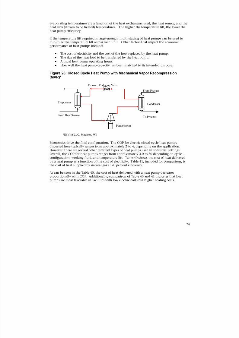
8/13/2019 Doebestpractice Casting
http://slidepdf.com/reader/full/doebestpractice-casting 75/116
evaporating temperatures are a function of the heat exchangers used, the heat source, and theheat sink (stream to be heated) temperatures. The higher the temperature lift, the lower theheat pump efficiency.
If the temperature lift required is large enough, multi-staging of heat pumps can be used tominimize the temperature lift across each unit. Other factors that impact the economic
performance of heat pumps include:
• The cost of electricity and the cost of the heat replaced by the heat pump.
• The size of the heat load to be transferred by the heat pump.
• Annual heat pump operating hours.• How well the heat pump capacity has been matched to its intended purpose.
Figure 28: Closed Cycle Heat Pump with Mechanical Vapor Recompression(MVR)*
Pressure Reducing Valve
Pump/motor
Condenser Evaporator
From Process
To ProcessFrom Heat Source
*EnVise LLC, Madison, WI
Economics drive the final configuration. The COP for electric closed-cycle heat pumpsdiscussed here typically ranges from approximately 2 to 4, depending on the application.However, there are several other different types of heat pumps used in industrial settings.Overall, the COP for heat pumps ranges from approximately 3.0 to 30 depending on cycleconfiguration, working fluid, and temperature lift. Table 40 shows the cost of heat deliveredby a heat pump as a function of the cost of electricity. Table 41, included for comparison, isthe cost of heat supplied by natural gas at 70 percent efficiency.
As can be seen in the Table 40, the cost of heat delivered with a heat pump decreasesproportionally with COP. Additionally, comparison of Table 40 and 41 indicates that heatpumps are most favorable in facilities with low electric costs but higher heating costs.
74
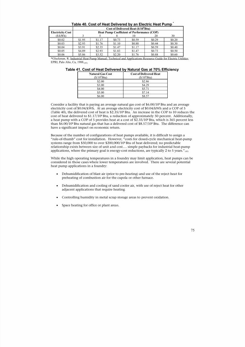
8/13/2019 Doebestpractice Casting
http://slidepdf.com/reader/full/doebestpractice-casting 76/116
Table 40. Cost of Heat Delivered by an Electric Heat Pump*
Cost of Delivered Heat ($/106Btu)
Electricity Cost($/kWh)
Heat Pump Coefficient of Performance (COP)3 5 8 10 20 30
$0.02 $1.95 $1.17 $0.73 $0.59 $0.29 $0.20
$0.03 $2.93 $1.76 $1.10 $0.88 $0.44 $0.30
$0.04 $3.91 $2.35 $1.47 $1.17 $0.59 $0.40$0.05 $4.89 $2.93 $1.83 $1.47 $0.73 $0.50
$0.06 $5.86 $3.52 $2.20 $1.76 $0.88 $0.60
*Gluckman, R, Industrial Heat Pump Manual; Technical and Applications Resource Guide for Electric Utilities,EPRI, Palo Alto, Ca, 1988.(42)
Table 41. Cost of Heat Delivered by Natural Gas at 70% EfficiencyNatural Gas Cost
($/106Btu)Cost of Delivered Heat
($/106Btu)
$2.00 $2.86
$3.00 $4.29
$4.00 $5.71
$5.00 $7.14$6.00 $8.57
Consider a facility that is paying an average natural gas cost of $6.00/106 Btu and an averageelectricity cost of $0.04/kWh. At an average electricity cost of $0.04/kWh and a COP of 5(Table 40), the delivered cost of heat is $2.35/106 Btu. An increase in the COP to 10 reduces thecost of heat delivered to $1.17/106 Btu, a reduction of approximately 50 percent. Additionally,a heat pump with a COP of 5 provides heat at a cost of $2.35/106 Btu, which is 365 percent lessthan $6.00/106 Btu natural gas that has a delivered cost of $8.57/106 Btu. The difference canhave a significant impact on economic return.
Because of the number of configurations of heat pumps available, it is difficult to assign a
“rule-of-thumb” cost for installation. However, “costs for closed-cycle mechanical heat-pumpsystems range from $50,000 to over $200,000/106 Btu of heat delivered; no predictablerelationship exists between size of unit and cost…. simple paybacks for industrial heat-pumpapplications, where the primary goal is energy-cost reductions, are typically 2 to 5 years.”(41)
While the high operating temperatures in a foundry may limit application, heat pumps can beconsidered in those cases where lower temperatures are involved. There are several potentialheat pump applications in a foundry:
• Dehumidification of blast air (prior to pre-heating) and use of the reject heat forpreheating of combustion air for the cupola or other furnace.
• Dehumidification and cooling of sand cooler air, with use of reject heat for otheradjacent applications that require heating.
• Controlling humidity in metal scrap storage areas to prevent oxidation.
• Space heating for office or plant areas.
75
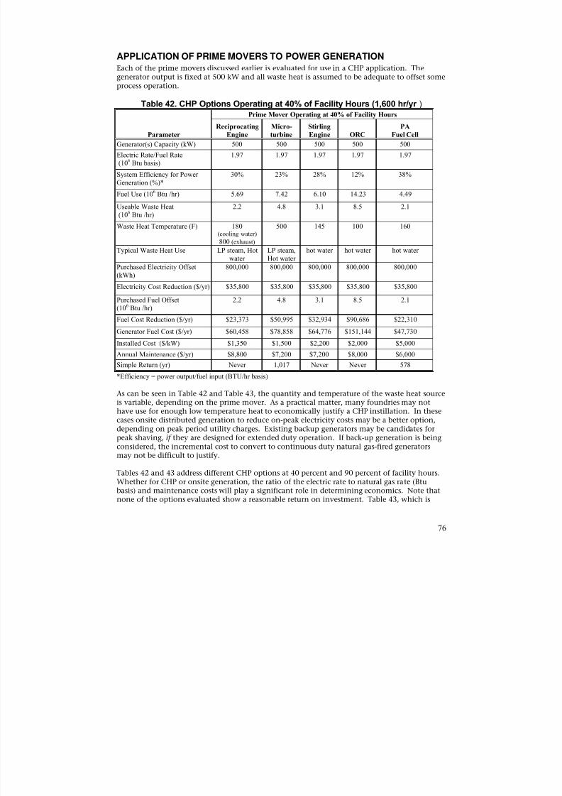
8/13/2019 Doebestpractice Casting
http://slidepdf.com/reader/full/doebestpractice-casting 77/116
APPLICATION OF PRIME MOVERS TO POWER GENERATIONEach of the prime movers discussed earlier is evaluated for use in a CHP application. Thegenerator output is fixed at 500 kW and all waste heat is assumed to be adequate to offset someprocess operation.
Table 42. CHP Options Operating at 40% of Facility Hours (1,600 hr/yr )
Parameter
Prime Mover Operating at 40% of Facility Hours
Reciprocating
Engine
Micro-
turbine
Stirling
Engine ORC
PA
Fuel Cell
Generator(s) Capacity (kW) 500 500 500 500 500
Electric Rate/Fuel Rate(106 Btu basis)
1.97 1.97 1.97 1.97 1.97
System Efficiency for PowerGeneration (%)*
30% 23% 28% 12% 38%
Fuel Use (106 Btu /hr) 5.69 7.42 6.10 14.23 4.49
Useable Waste Heat
(106
Btu /hr)
2.2 4.8 3.1 8.5 2.1
Waste Heat Temperature (F) 180(cooling water)
800 (exhaust)
500 145 100 160
Typical Waste Heat Use LP steam, Hotwater
LP steam,Hot water
hot water hot water hot water
Purchased Electricity Offset(kWh)
800,000 800,000 800,000 800,000 800,000
Electricity Cost Reduction ($/yr) $35,800 $35,800 $35,800 $35,800 $35,800
Purchased Fuel Offset(106 Btu /hr)
2.2 4.8 3.1 8.5 2.1
Fuel Cost Reduction ($/yr) $23,373 $50,995 $32,934 $90,686 $22,310Generator Fuel Cost ($/yr) $60,458 $78,858 $64,776 $151,144 $47,730
Installed Cost ($/kW) $1,350 $1,500 $2,200 $2,000 $5,000
Annual Maintenance ($/yr) $8,800 $7,200 $7,200 $8,000 $6,000
Simple Return (yr) Never 1,017 Never Never 578
*Efficiency = power output/fuel input (BTU/hr basis)
As can be seen in Table 42 and Table 43, the quantity and temperature of the waste heat sourceis variable, depending on the prime mover. As a practical matter, many foundries may nothave use for enough low temperature heat to economically justify a CHP instillation. In thesecases onsite distributed generation to reduce on-peak electricity costs may be a better option,
depending on peak period utility charges. Existing backup generators may be candidates forpeak shaving, if they are designed for extended duty operation. If back-up generation is beingconsidered, the incremental cost to convert to continuous duty natural gas-fired generatorsmay not be difficult to justify.
Tables 42 and 43 address different CHP options at 40 percent and 90 percent of facility hours.Whether for CHP or onsite generation, the ratio of the electric rate to natural gas rate (Btubasis) and maintenance costs will play a significant role in determining economics. Note thatnone of the options evaluated show a reasonable return on investment. Table 43, which is
76
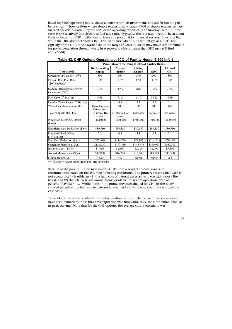
8/13/2019 Doebestpractice Casting
http://slidepdf.com/reader/full/doebestpractice-casting 78/116
based on 3,600 operating hours, shows a better return on investment, but still far too long tobe practical. Those options where simple return on investment (ROI or simple return) that aremarked “never” because they are considered operating expenses. The limiting factor in thesecases is the relatively low electric to fuel rate ratio. Typically, the rate ratio needs to be at aboutthree or better for CHP instillations to have any potential for financial success. Also note thatwhile the ORC does not show a ROI, this is the case when using natural gas as a fuel. The
capacity of the ORC to use waste heat in the range of 225°F to 500°F may make it more suitablefor power generation through waste heat recovery, which means that ORC may still findapplicability.
Table 43. CHP Options Operating at 90% of Facility Hours (3,600 hr/yr)
Parameter
Prime Mover Operating at 90% of Facility Hours
Reciprocating
Engine
Micro-
turbine
Stirling
Engine ORC
PA Fuel
Cell
Generator(s) Capacity (kW) 500 500 500 500 500
Electric Rate/Fuel Rate(106 Btu basis)
1.97 1.97 1.97 1.97 1.97
System Efficiency for PowerGeneration (%)*
30% 23% 28% 12% 38%
Fuel Use (106 Btu /hr) 5.69 7.42 6.10 14.23 4.49
Useable Waste Heat (106 Btu /hr) 2.2 4.8 3.1 8.5 2.1
Waste Heat Temperature (F) 180 (cooling water)
800 (exhaust)
500 145 100 160
Typical Waste Heat Use LP steam, Hotwater
LP steam, Hotwater
hot water hot water hot water
Purchased Electricity Offset(kWh)
1,800,000 1,800,000 1,800,000 1,800,000 1,800,000
Electricity Cost Reduction ($/yr) $80,550 $80,550 $80,550 $80,550 $80,550
Purchased Fuel Offset(106 Btu /hr)
2.2 4.8 3.1 8.5 2.1
Fuel Cost Reduction ($/yr) $52,589 $114,739 $74,102 $204,205 $50,198
Generator Fuel Cost ($/yr) $136,030 $177,430 $145,746 $340,074 $107,392
Installed Cost ($/kW) $1,350 $1,500 $2,200 $2,000 $5,500
Annual Maintenance ($/yr) $19,800 $16,200 $16,200 $18,000 $13,500
Simple Return (yr) Never 452 Never Never 254
*Efficiency = power output/fuel input (Btu/hr basis)
Because of the poor return on investment, CHP is not a good candidate, and is notrecommended, based on the assumed operating conditions. The primary reasons that CHP is
not economically feasible are (1) the high cost of natural gas relative to electricity (on a Btubasis), and (2) the relatively low annual hours available for system operation, even at 90percent of availability. While none of the prime movers evaluated for CHP in this studyshowed potential, the best way to determine whether CHP will be successful is on a case-bycase basis.
Table 44 addresses the onsite distributed generation options. The prime movers consideredhave been reduced to those that have rapid response times and, thus, are more suitable for usein peak shaving. Note that for the CHP options, the average cost of electricity was
77
8/13/2019 Doebestpractice Casting
http://slidepdf.com/reader/full/doebestpractice-casting 79/116
$0.04475/kWh; however, if $0.04475/kWh is the average cost of electricity, the on-peak costwill be higher. An on-peak cost of $0.080/kWh was assumed for estimation purposes, sincepeak shaving primarily occurs during on-peak time. Thus, the electric to fuel rate ratio ishigher than for the CHP options due to the greater electricity cost during peak periods. Typicalon-peak times are 10 a.m. to 10 p.m. (12 hours/day, 5days/week), which amounts to 3,000hours per year.
Even though the electric to fuel rate ratio is greater than 3.5, the overall system efficiency ismuch lower than for CHP, due to the absence of heat recovery. The end result in this case ispoor economic performance; the systems as evaluated are an operating expense.
Table 44. On-Site Distributed GenerationOperating During Peak Hours (3,000 hr/yr)
Parameter
Reciprocating
Engine Microturbine
Generator(s) Capacity (kW) 500 500
Electric to Fuel Ratio (106 Btu basis)
3.53 3.53
System Efficiency for PowerGeneration (%)
30% 23%
Fuel Use (106 Btu /hr) 5.69 7.42
Purchased Electricity Offset (kWh) 1,500,000 1,500,000
Electricity Cost Reduction ($/yr) $120,000 $120,000
Generator Fuel Cost ($/yr) $113,358 $147,858
Installed Cost ($/kW) $800 $800
Annual Maintenance ($/yr) $16,500 $13,500
Simple Return (yr) Never Never
Because of the poor ROI, DG is not a good candidate, and is not recommended, based on the
assumed operating conditions. The primary reason that DG is not economically feasible is thehigh cost of natural gas relative to on-peak electricity (on a Btu basis). While neither of theprime movers evaluated for DG in this study showed potential, the best way to determinewhether DG can be successful is on a case-by-case basis.
ASSESSMENT OF GENERATION POTENTIAL FOR SPECIFIC FOUNDRYOPERATIONS
Exergy analysis was used to provide a basis against which the potential for power generationfor the following foundry processes can be measured:
• Cupola melting furnaces
• Aluminum stack melters• Steel casting heat treating processes
• Ductile iron pipe heat treating processes
Consideration of the quantity and temperature of the heat available from process exhaustaddresses the potential for power generation based only on the physical state of the streamsand is thus called “physical” exergy analysis. The composition of the exhaust is assumed tonot change during energy recovery. Additionally, any particulate matter contained in theexhaust is considered inert, not contributing to or taking away from this potential.
78
8/13/2019 Doebestpractice Casting
http://slidepdf.com/reader/full/doebestpractice-casting 80/116
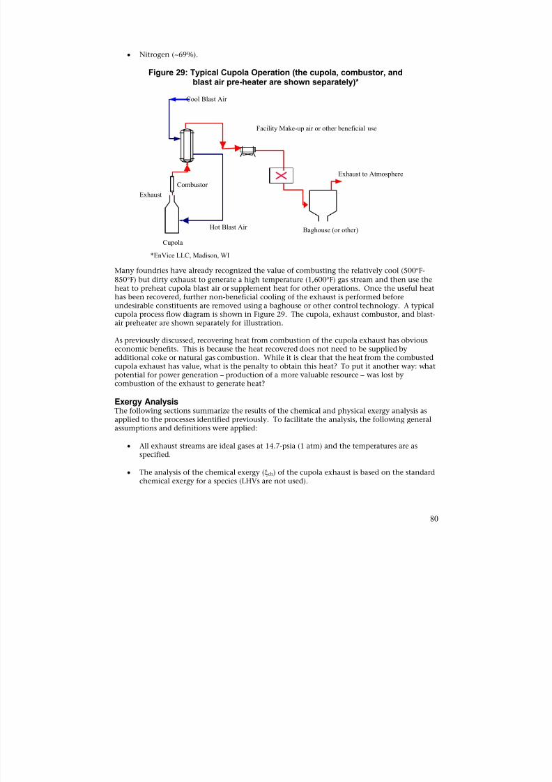
8/13/2019 Doebestpractice Casting
http://slidepdf.com/reader/full/doebestpractice-casting 81/116
• Nitrogen (~69%).
Figure 29: Typical Cupola Operation (the cupola, combustor, andblast air pre-heater are shown separately)*
Cool Blast Air
Hot Blast Air
Exhaust
Combustor
Baghouse (or other)
Exhaust to Atmosphere
Facility Make-up air or other beneficial use
Cupola
*EnVice LLC, Madison, WI
Many foundries have already recognized the value of combusting the relatively cool (500°F
850°F) but dirty exhaust to generate a high temperature (1,600°F) gas stream and then use theheat to preheat cupola blast air or supplement heat for other operations. Once the useful heathas been recovered, further non-beneficial cooling of the exhaust is performed beforeundesirable constituents are removed using a baghouse or other control technology. A typical
cupola process flow diagram is shown in Figure 29. The cupola, exhaust combustor, and blast-air preheater are shown separately for illustration.
As previously discussed, recovering heat from combustion of the cupola exhaust has obviouseconomic benefits. This is because the heat recovered does not need to be supplied byadditional coke or natural gas combustion. While it is clear that the heat from the combustedcupola exhaust has value, what is the penalty to obtain this heat? To put it another way: whatpotential for power generation – production of a more valuable resource – was lost bycombustion of the exhaust to generate heat?
Exergy AnalysisThe following sections summarize the results of the chemical and physical exergy analysis as
applied to the processes identified previously. To facilitate the analysis, the following generalassumptions and definitions were applied:
• All exhaust streams are ideal gases at 14.7-psia (1 atm) and the temperatures are asspecified.
• The analysis of the chemical exergy (ξch) of the cupola exhaust is based on the standardchemical exergy for a species (LHVs are not used).
80
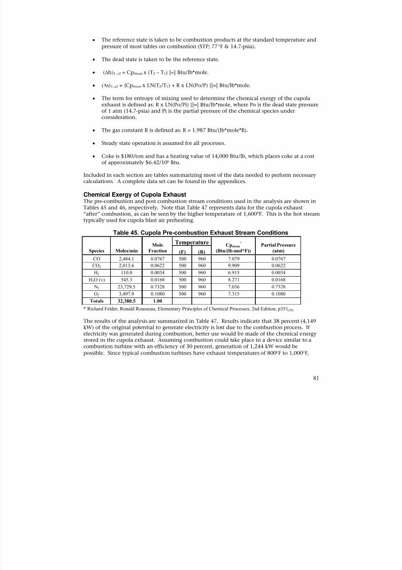
8/13/2019 Doebestpractice Casting
http://slidepdf.com/reader/full/doebestpractice-casting 82/116
• The reference state is taken to be combustion products at the standard temperature and
pressure of most tables on combustion (STP; 77°F & 14.7-psia).
• The dead state is taken to be the reference state.
• (∆h)1→2 = Cpmean x (T2 – T1) [=] Btu/lb*mole.
• (∆s)1→2 = {Cpmean x LN(T2/T1) + R x LN(Po/P) }[=] Btu/lb*mole.
• The term for entropy of mixing used to determine the chemical exergy of the cupolaexhaust is defined as: R x LN(Po/Pi) }[=] Btu/lb*mole, where Po is the dead state pressureof 1 atm (14.7-psia) and Pi is the partial pressure of the chemical species underconsideration.
• The gas constant R is defined as: R = 1.987 Btu/(lb*mole*R).
• Steady state operation is assumed for all processes.
• Coke is $180/ton and has a heating value of 14,000 Btu/lb, which places coke at a costof approximately $6.42/106 Btu.
Included in each section are tables summarizing most of the data needed to perform necessarycalculations. A complete data set can be found in the appendices.
Chemical Exergy of Cupola ExhaustThe pre-combustion and post combustion stream conditions used in the analysis are shown inTables 45 and 46, respectively. Note that Table 47 represents data for the cupola exhaust“after” combustion, as can be seen by the higher temperature of 1,600ºF. This is the hot streamtypically used for cupola blast air preheating.
Table 45. Cupola Pre-combustion Exhaust Stream Conditions
Species Moles/min
Mole
Fraction
TemperatureCpmean
*
(Btu/(lb-mol*F))
Partial Pressure
(atm)(F) (R)
CO 2,484.1 0.0767 500 960 7.079 0.0767
CO2 2,013.6 0.0622 500 960 9.909 0.0622
H2 110.0 0.0034 500 960 6.915 0.0034
H2O (v) 545.3 0.0168 500 960 8.271 0.0168
N2 23,729.5 0.7328 500 960 7.036 0.7328
O2 3,497.9 0.1080 500 960 7.315 0.1080
Totals 32,380.5 1.00
* Richard Felder, Ronald Rousseau, Elementary Principles of Chemical Processes, 2nd Edition, p351(30)
The results of the analysis are summarized in Table 47. Results indicate that 38 percent (4,149kW) of the original potential to generate electricity is lost due to the combustion process. Ifelectricity was generated during combustion, better use would be made of the chemical energystored in the cupola exhaust. Assuming combustion could take place in a device similar to acombustion turbine with an efficiency of 30 percent, generation of 1,244 kW would be
possible. Since typical combustion turbines have exhaust temperatures of 800°F to 1,000°F,
81
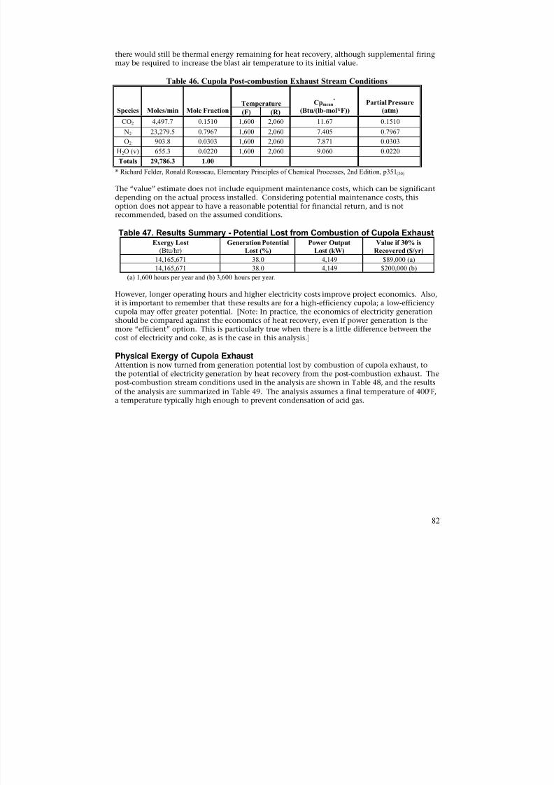
8/13/2019 Doebestpractice Casting
http://slidepdf.com/reader/full/doebestpractice-casting 83/116
there would still be thermal energy remaining for heat recovery, although supplemental firingmay be required to increase the blast air temperature to its initial value.
Table 46. Cupola Post-combustion Exhaust Stream Conditions
Species Moles/min Mole Fraction Temperature Cpmean
*
(Btu/(lb-mol*F)) Partial Pressure(atm)(F) (R)
CO2 4,497.7 0.1510 1,600 2,060 11.67 0.1510
N2 23,279.5 0.7967 1,600 2,060 7.405 0.7967
O2 903.8 0.0303 1,600 2,060 7.871 0.0303
H2O (v) 655.3 0.0220 1,600 2,060 9.060 0.0220
Totals 29,786.3 1.00
* Richard Felder, Ronald Rousseau, Elementary Principles of Chemical Processes, 2nd Edition, p351(30)
The “value” estimate does not include equipment maintenance costs, which can be significantdepending on the actual process installed. Considering potential maintenance costs, thisoption does not appear to have a reasonable potential for financial return, and is not
recommended, based on the assumed conditions.
Table 47. Results Summary - Potential Lost from Combustion of Cupola ExhaustExergy Lost
(Btu/hr)Generation Potential
Lost (%)
Power Output
Lost (kW)
Value if 30% is
Recovered ($/yr)
14,165,671 38.0 4,149 $89,000 (a)
14,165,671 38.0 4,149 $200,000 (b)
(a) 1,600 hours per year and (b) 3,600 hours per year.
However, longer operating hours and higher electricity costs improve project economics. Also,it is important to remember that these results are for a high-efficiency cupola; a low-efficiencycupola may offer greater potential. [Note: In practice, the economics of electricity generation
should be compared against the economics of heat recovery, even if power generation is themore “efficient” option. This is particularly true when there is a little difference between thecost of electricity and coke, as is the case in this analysis.]
Physical Exergy of Cupola ExhaustAttention is now turned from generation potential lost by combustion of cupola exhaust, tothe potential of electricity generation by heat recovery from the post-combustion exhaust. Thepost-combustion stream conditions used in the analysis are shown in Table 48, and the results
of the analysis are summarized in Table 49. The analysis assumes a final temperature of 400°F,a temperature typically high enough to prevent condensation of acid gas.
82
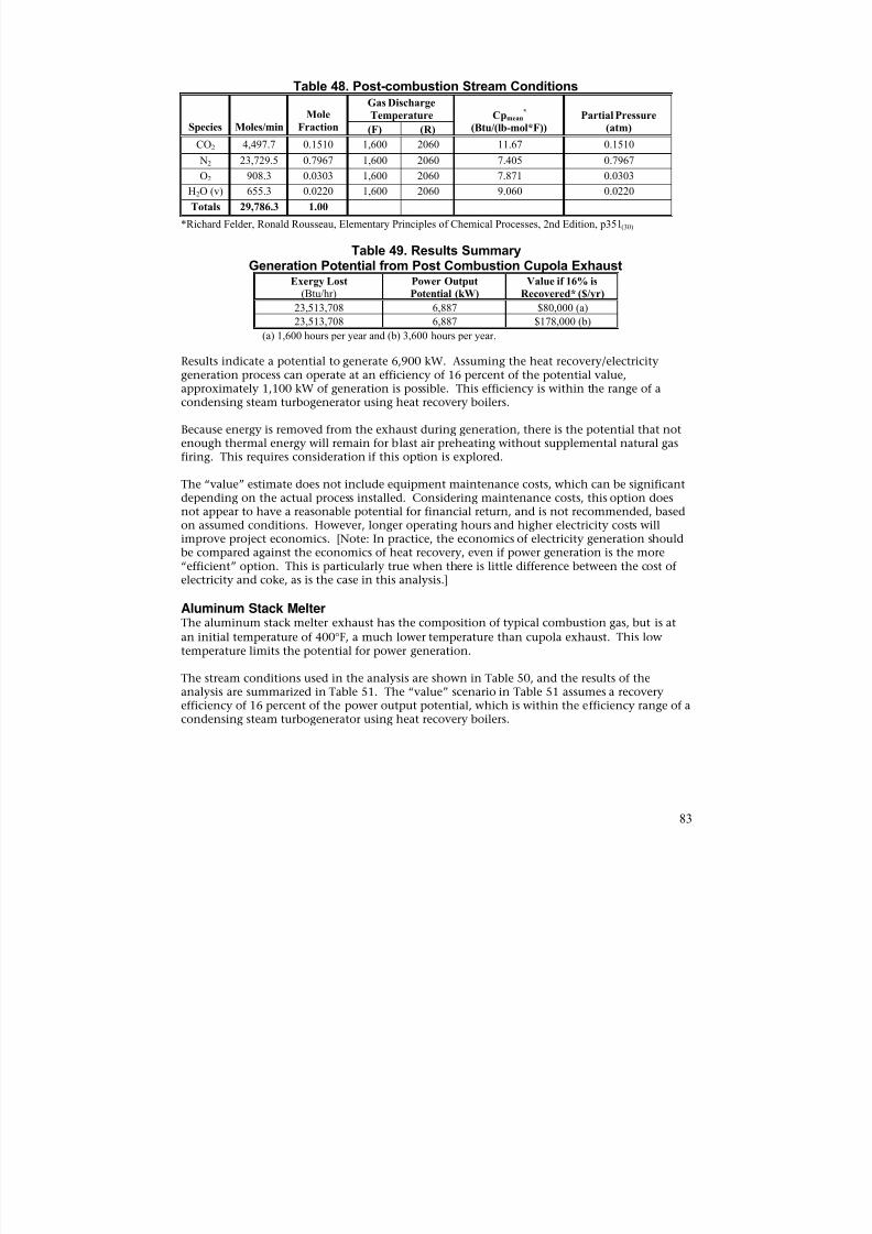
8/13/2019 Doebestpractice Casting
http://slidepdf.com/reader/full/doebestpractice-casting 84/116
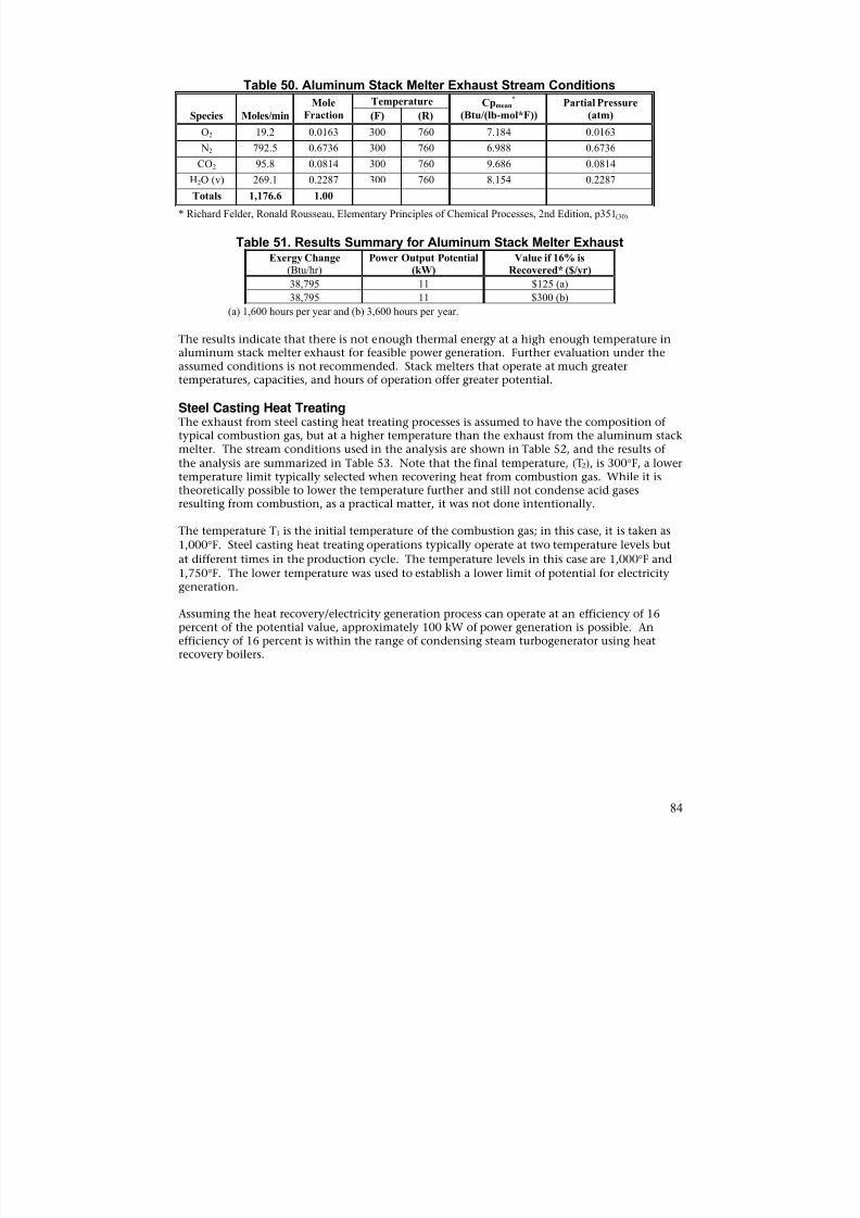
8/13/2019 Doebestpractice Casting
http://slidepdf.com/reader/full/doebestpractice-casting 85/116
Table 50. Aluminum Stack Melter Exhaust Stream Conditions
Species Moles/min
Mole
Fraction
Temperature Cpmean*
(Btu/(lb-mol*F))
Partial Pressure
(atm)(F) (R)
O2 19.2 0.0163 300 760 7.184 0.0163
N2 792.5 0.6736 300 760 6.988 0.6736
CO2 95.8 0.0814 300 760 9.686 0.0814H2O (v) 269.1 0.2287 300 760 8.154 0.2287
Totals 1,176.6 1.00
* Richard Felder, Ronald Rousseau, Elementary Principles of Chemical Processes, 2nd Edition, p351(30)
Table 51. Results Summary for Aluminum Stack Melter ExhaustExergy Change
(Btu/hr)Power Output Potential
(kW)
Value if 16% is
Recovered* ($/yr)
38,795 11 $125 (a)
38,795 11 $300 (b)
(a) 1,600 hours per year and (b) 3,600 hours per year.
The results indicate that there is not enough thermal energy at a high enough temperature inaluminum stack melter exhaust for feasible power generation. Further evaluation under theassumed conditions is not recommended. Stack melters that operate at much greatertemperatures, capacities, and hours of operation offer greater potential.
Steel Casting Heat TreatingThe exhaust from steel casting heat treating processes is assumed to have the composition oftypical combustion gas, but at a higher temperature than the exhaust from the aluminum stackmelter. The stream conditions used in the analysis are shown in Table 52, and the results ofthe analysis are summarized in Table 53. Note that the final temperature, (T2), is 300°F, a lowertemperature limit typically selected when recovering heat from combustion gas. While it is
theoretically possible to lower the temperature further and still not condense acid gasesresulting from combustion, as a practical matter, it was not done intentionally.
The temperature T1 is the initial temperature of the combustion gas; in this case, it is taken as1,000°F. Steel casting heat treating operations typically operate at two temperature levels but
at different times in the production cycle. The temperature levels in this case are 1,000°F and1,750°F. The lower temperature was used to establish a lower limit of potential for electricitygeneration.
Assuming the heat recovery/electricity generation process can operate at an efficiency of 16percent of the potential value, approximately 100 kW of power generation is possible. Anefficiency of 16 percent is within the range of condensing steam turbogenerator using heat
recovery boilers.
84

8/13/2019 Doebestpractice Casting
http://slidepdf.com/reader/full/doebestpractice-casting 86/116
Table 52. Steel Casting Heat Treating Exhaust Stream Conditions
Species
Estimated CompositionCpmean @T1
*
Btu/
(lb-mol*F)
Cpmean @T1*
Btu/(mol*F)
Cpmean @T2*
Btu/
(lb-mol*F)
Cpmean @T2*
Btu/(mol*F)(moles) (mole fraction)
CO2 118,055,898 0.082 11.78 0.025947137 9.686 0.021334802
N2 972,024,149 0.674 7.443 0.016394273 7.011 0.015442731
O2 23,489,651 0.016 7.909 0.017420705 7.251 0.015971366
H2O(v) 328,832,964 0.228 9.138 0.020127753 8.211 0.018085903
Totals 1,442,402,662 1.00
* Richard Felder, Ronald Rousseau, Elementary Principles of Chemical Processes, 2nd Edition, p351 (30)
Table 53 Results Summary for Steel Casting Heat Treating Exhaust*
Exergy Change(Btu/hr)
Power Output Potential
(kW)
Value if 16% is Recovered*
($/yr)
2,295,395 672 $8,000 (a)
2,295,395 672 $18,000 (b)
(a) 1,600 hours per year and (b) 3,600 hours per year.
The “value” estimate does not include equipment maintenance costs, which can be significantdepending on the actual process installed. Considering maintenance costs, this option doesnot appear to have a reasonable potential for financial return, and is not recommended, basedon assumed conditions. However, longer operating hours and higher electricity costs willimprove project economics. [Note: In practice, the economics of electricity generation need tobe compared against the economics of heat recovery, even if power generation is the more“efficient” option. This is particularly true when there is little difference between the cost ofelectricity and natural gas, as is the case in this analysis.]
Ductile Iron Pipe Heat TreatingThe combustion exhaust from ductile iron pipe, heat treating processes is similar in
composition to that of steel casting heat treating combustion processes. However, the exhaustfrom the ductile iron-pipe heat treating process is 1,740°F, a much higher temperature. Thestream conditions used in the analysis are shown in Table 54 and the results of the analysis are
summarized in Table 55. Note that as before, the final temperature, T2, is 300°F, a lowertemperature limit typically selected when recovering heat from combustion gas. While it istheoretically possible to lower the temperature further and still not condense acid gasesresulting from combustion, as a practical matter, it was not done intentionally.
Assuming the heat recovery/electricity generation process can operate at an efficiency of 16percent of the potential value, approximately 260 kW of generation is possible. An efficiencyof 16 percent is within the range of a condensing steam turbogenerator utilizing heat recoveryboilers.
85
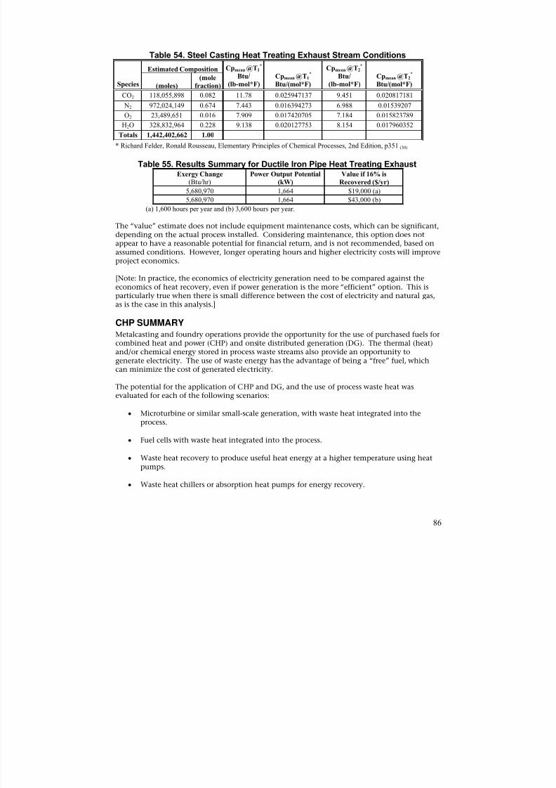
8/13/2019 Doebestpractice Casting
http://slidepdf.com/reader/full/doebestpractice-casting 87/116
Table 54. Steel Casting Heat Treating Exhaust Stream Conditions
Species
Estimated Composition Cpmean @T1*
Btu/
(lb-mol*F)
Cpmean @T1*
Btu/(mol*F)
Cpmean @T2*
Btu/
(lb-mol*F)
Cpmean @T2*
Btu/(mol*F)(moles)
(mole
fraction)
CO2 118,055,898 0.082 11.78 0.025947137 9.451 0.020817181
N2 972,024,149 0.674 7.443 0.016394273 6.988 0.01539207O2 23,489,651 0.016 7.909 0.017420705 7.184 0.015823789
H2O 328,832,964 0.228 9.138 0.020127753 8.154 0.017960352
Totals 1,442,402,662 1.00
* Richard Felder, Ronald Rousseau, Elementary Principles of Chemical Processes, 2nd Edition, p351 (30)
Table 55. Results Summary for Ductile Iron Pipe Heat Treating ExhaustExergy Change
(Btu/hr)Power Output Potential
(kW)
Value if 16% is
Recovered ($/yr)
5,680,970 1,664 $19,000 (a)
5,680,970 1,664 $43,000 (b)
(a) 1,600 hours per year and (b) 3,600 hours per year.
The “value” estimate does not include equipment maintenance costs, which can be significant,depending on the actual process installed. Considering maintenance, this option does notappear to have a reasonable potential for financial return, and is not recommended, based onassumed conditions. However, longer operating hours and higher electricity costs will improveproject economics.
[Note: In practice, the economics of electricity generation need to be compared against theeconomics of heat recovery, even if power generation is the more “efficient” option. This isparticularly true when there is small difference between the cost of electricity and natural gas,as is the case in this analysis.]
CHP SUMMARYMetalcasting and foundry operations provide the opportunity for the use of purchased fuels forcombined heat and power (CHP) and onsite distributed generation (DG). The thermal (heat)and/or chemical energy stored in process waste streams also provide an opportunity togenerate electricity. The use of waste energy has the advantage of being a “free” fuel, whichcan minimize the cost of generated electricity.
The potential for the application of CHP and DG, and the use of process waste heat wasevaluated for each of the following scenarios:
• Microturbine or similar small-scale generation, with waste heat integrated into the
process.
• Fuel cells with waste heat integrated into the process.
• Waste heat recovery to produce useful heat energy at a higher temperature using heatpumps.
• Waste heat chillers or absorption heat pumps for energy recovery.
86
8/13/2019 Doebestpractice Casting
http://slidepdf.com/reader/full/doebestpractice-casting 88/116
• Trigeneration (combined cooling, heating, and power).
The prime movers most suitable for CHP are those that provide waste heat at a high enoughtemperature to be useable the greatest amount of time. Five different prime movers wereconsidered for CHP use:
• Reciprocating engines;• Microturbines;
• Stirling engines;
• Organic Rankine Cycle turbogenerators; and
• Phosphoric acid fuel cells.
Each of these prime movers was evaluated assuming (1) an output of 500 kW and (2) all wasteheat generated is useable within a facility.
Onsite distributed generation (no heat recovery) was evaluated only for microturbines andreciprocating engines, assuming an output of 500 kW. A generator output of 500 kW waschosen because it appears to be a small enough capacity to be suitable for use in most
foundries. Because of the many sources of waste energy in foundries, only four high-energyrecovery potential operations were considered as candidates to evaluate the potential forgeneration of electricity. The four operations include:
• High-efficiency cupola melting furnaces (cast iron);
• Aluminum stack melters;• Steel casting heat-treat processes; and
• Ductile iron pipe heat-treat processes.
The data used in the analysis of the waste energy potential represents, to the greatest extentpossible, average values representative of those that would be encountered in the field. Thus,the results are general in nature and intended to serve only as a guide for potential application.
Because the “waste” energy is essentially free, there is no additional fuel cost incurred forequipment operation unless supplemental firing is required, although maintenance costs alsomerit consideration. Examples of electricity generation from waste energy are the use of (1)high-quality (temperature) heat to generate steam to drive a steam turbogenerator, or (2) lower
grade waste heat (400°F to 500°F) to drive an Organic Rankine Cycle (ORC) turbogenerator.
To allow estimation of the economic potential, the following utility rates were assumed:
• Natural gas is $6.63/106 Btu.
• Coke is $180/ton ($6.42/106 Btu).
• Electricity is $0.04475/kWh, on average.
• Electricity is $0.080/kWh during on-peak time.
• Operating hours are based on a 16-hour, 5-day workweek, 50 weeks per year. Since theprocesses under consideration may have widely varying operating hours at any given
87
8/13/2019 Doebestpractice Casting
http://slidepdf.com/reader/full/doebestpractice-casting 89/116
facility, benefits are shown based on 40 percent and 90 percent availability duringoperating hours.
CHPNone of the prime movers evaluated for CHP using purchased fuels show reasonable potentialfor success, and are not recommended for consideration under the assumed conditions. ROIs
were either found to be greater than 100 years, or the systems would actually be an operatingexpense. The primary reasons that CHP is not economically feasible are (1) the high cost ofnatural gas relative to electricity (on a Btu basis), and (2) the relatively low annual hoursavailable for system operation, even at 90 percent availability. While none of the primemovers evaluated for CHP in this study showed potential, the best way to determine whetherCHP will be successful is on a case-by-case basis.
Onsite Distributed Generation (DG)None of the prime movers evaluated for DG using purchased fuels show reasonable potentialfor success; thus, DG is not recommended for consideration under the assumed conditions.The primary reason that DG is not economically feasible is the high cost of natural gas relativeto on-peak electricity (Btu basis). While neither of the prime movers evaluated for DG in this
study shows potential, the best way to determine whether DG can be successful is on a case-bycase basis.
Heat Recovery – Use of Thermally-Activated ChillerThermal chillers use a heat source to produce a desired cooling effect. When the cost ofpurchased fuels is low or a waste heat source is available, thermal chillers can offer relativelylow cost cooling. The foundry industry does not, however, appear to have a large-scale needfor refrigerated cooling, and related options are not likely to be economically feasible on thebasis of energy alone. However, there may be other economic benefits. For example, if theavailability of a constant, low-temperature source reduces product cool down time, increases inproduction rate may result. Because of the potential benefit, it is recommended that thermalchillers be considered in those cases where refrigerated chilling is in place, or when other
benefits may result. Information was included for those who wish to consider thermal chillers.
Heat Recovery—Heat PumpA heat pump moves energy from a source at a lower temperature to meet heat loadrequirements at another temperature. There are several different types of heat pumps typically
used in industrial settings. While the low, upper temperature capability of 200°F to 250°F willlikely limit use in foundries or metalcasting operations, it is recommended that heat pumps beconsidered in those cases where lower temperatures are involved. There are several potentialheat pump applications in a foundry:
• Dehumidification of blast air (prior to heating) and use of the reject heat for preheatingof combustion air for the cupola or other furnace.
• Dehumidification and cooling of sand cooler air, with use of reject heat for otheradjacent applications that require heating.
• Controlling humidity in metal scrap storage areas to prevent metal oxidation.
• Space heating for office or plant areas.
88

8/13/2019 Doebestpractice Casting
http://slidepdf.com/reader/full/doebestpractice-casting 90/116
Some basic information on heat pumps was included for informational purposes.
High-Efficiency Cupola Melting Furnace (cast iron)The cupola furnace showed by far the greatest potential of the four process operationsconsidered. The high-efficiency cupola was the only one considered because of the significantadvantages of converting low-efficiency cupolas to high-efficiency designs. To determine
power generation potential, two scenarios were evaluated:
1. The power generation potential lost due to combustion of exhaust for blast airpreheating; and
2. The power generation potential of the hot gas after combustion, but before blast airpreheating.
1. Power generation potential lost due to combustion of cupola exhaustApplication of exergy analysis indicated that during combustion of the cupola exhaust forpreheating blast air, approximately 38 percent of the potential to generate electricity, or 4,200kW, is lost. This lost generation potential cannot be regained by heat recovery. Thus, the
value in terms of electricity is gone as well. However, assuming that a combustion turbinewith an efficiency of 30 percent is used to generate electricity during combustion of the cupolaexhaust, the generation potential is approximately 1,200 kW.
Combustion of the cupola exhaust for power generation makes less thermal energy available
for blast air preheating. Since typical combustion turbines have exhaust temperatures of 800°F
to 1,000°F, it may be necessary to use supplemental firing with natural gas or another fuel toelevate blast air to the desired temperature. Considering potential maintenance costs and thelow cost of electricity, this option does not appear to have a reasonable potential for financialreturn, and is not recommended, based on the assumed conditions. However, longer operatinghours and higher electricity cost will improve project economics.
2. Power generation potential of the hot cupola exhaust after combustionApplication of exergy analysis indicates that the potential for power generation from the hotcupola exhaust is approximately 6,900 kW. However, assuming that the heatrecovery/generation process efficiency is 16 percent, the generation potential is approximately1,100 kW.
Considering potential maintenance costs and the low cost of electricity, this option does notappear to have a reasonable potential for financial return, and is not recommended, based onthe assumed conditions. However, longer operating hours and higher electricity will improveproject economics.
Aluminum Stack Melter Exhaust
The low temperature of the aluminum stack melter exhaust (400°F) makes this a poorcandidate for power generation using waste heat recovery. The theoretical potential wasestimated at 11 kW. This option is not recommended for further consideration, based on theassumed conditions. The stack melter was the only furnace considered because of thesignificant energy reduction potential of upgrading other furnace designs to this technology.
89

8/13/2019 Doebestpractice Casting
http://slidepdf.com/reader/full/doebestpractice-casting 91/116
Steel Casting Heat TreatingAt an exhaust temperature of 1,000°F, the steel casting heat treating exhaust shows atheoretical potential of approximately 670 kW, with a realistic potential of approximately 100kW, assuming a heat recovery/generation efficiency of 16 percent. However, the temperatureof the exhaust is at 1,000°F for part of the time and at 1,750°F for the remainder of operatinghours. Depending on actual temperature, the potential may be higher.
Considering potential maintenance costs and the low cost of electricity, this option does notappear to have a reasonable potential for financial return, and is not recommended, based onthe assumed conditions. However, longer operating hours and higher electricity costs willimprove project economics.
Ductile Iron Pipe Heat TreatingAt an exhaust temperature of 1,740°F, the ductile iron pipe heat-treat exhaust shows atheoretical potential of approximately 1,700 kW. The realistic potential is approximately 260kW assuming a heat recovery/generation efficiency of 16 percent.
Considering potential maintenance costs and the low cost of electricity, this option does notappear to have a reasonable potential for financial return, and is not recommended, based onthe assumed conditions. However, longer operating hours and higher electricity cost willimprove project economics.
90
8/13/2019 Doebestpractice Casting
http://slidepdf.com/reader/full/doebestpractice-casting 92/116
GLOSSARY OF TERMS
Absorption Chiller: An absorption chiller uses heat instead of mechanical energy to providecooling. A thermal compressor consists of an absorber, a generator, a pump, and a throttlingdevice, and replaces the mechanical vapor compressor. In the chiller, refrigerant vapor fromthe evaporator is absorbed by a solution mixture in the absorber. This solution is then pumpedto the generator, where the refrigerant re-vaporizes using a waste steam heat source. Therefrigerant-depleted solution then returns to the absorber via a throttling device. The two mostcommon refrigerant/absorbent mixtures used in absorption chillers are water/lithium bromideand ammonia/water.
Adsorption Chiller: An adsorption chiller uses heat instead of mechanical energy to providecooling. Instead of circulating a liquid-absorbent-medium, solid adsorbents (i.e. desiccant) areemployed in components that switch function with time. First, they adsorb refrigerant froman evaporator and reject heat to the environment until filled to capacity. In a second step theyare heated to drive off the refrigerant, which goes to a condenser for reuse until fullyregenerated. In these systems, the solution pump is replaced with a set of switching valves.
Best Practice: In this report, the term is defined to be the achievable state of operation in afacility with the best current technology.
Coefficient of Performance (COP): COP is the ratio of the rate of heat rejection (forrefrigeration) or heat supply (for heat pump) to the rate of energy input in consistent units.COP is used to measure the efficiency of refrigeration cycles and heat pump cycles.
Coke (coal): A solid carbonaceous residue derived from low-ash, low-sulfur bituminous coalfrom which the volatile constituents are driven off by baking in an oven at temperatures ashigh as 2,000 degrees Fahrenheit so that the fixed carbon and residual ash are fused together.Coke is used as a fuel and as a reducing agent in smelting iron ore in a blast furnace. Cokefrom coal is grey, hard, and porous, and has a heating value of approximately 26.0 million Btu
per ton.
Combined Heat and Power (CHP): A plant designed to produce both heat and electricity froma single heat source.
Distributed Generation (DG): Distributed generation is any small-scale power generationtechnology that provides electric power at a site closer to customers than central stationgeneration. A distributed power unit can be connected directly to the consumer or to a utility'stransmission or distribution system.
Exergy: Maximum theoretical work obtainable as a system interacts with the environment toequilibrium.
Fuel Cell: A device capable of generating an electrical current by converting the chemicalenergy of a fuel (e.g. hydrogen) directly into electrical energy. Fuel cells differ fromconventional electrical cells in that the active materials such as fuel and oxygen are notcontained within the cell, but are supplied from outside. It does not contain an intermediateheat cycle, as do most other electrical generation techniques.
Heat Pump: Heating and/or cooling equipment that draws heat into a building from outsideduring the heating season and ejects heat from the building to the outside during the cooling
91

8/13/2019 Doebestpractice Casting
http://slidepdf.com/reader/full/doebestpractice-casting 93/116
season. Heat pumps are vapor-compression refrigeration systems whose indoor/outdoor coilsare used reversibly as condensers or evaporators, depending on the need for heating or cooling.
Hysteresis: The phenomenon of lost energy that occurs during any cycle of loading orunloading when a material is subject to repeated loading.
Industry Average Energy Use: A baseline of current foundry energy usage based on the bestavailable information.
Microturbine: A centrifugal generator that operates in a similar fashion to a combustionturbine, except that the turbine rotor spins at a much higher speed. Microturbines use organicfuels, such as fuel oil, propane, or natural gas. A single unit can be configured to operate onmore than one fuel to allow for switching capability.
Onsite Energy: Onsite energy is the energy used within a facility. This is sometimes called“primary energy.” Electrical onsite energy is the kilowatt hours used and does not include the“secondary energy” required for generation and transmission of electricity.
Organic Rankine Cycle Turbogenerator: An Organic Rankine Cycle Turbogenerator operatessimilarly to the Rankine Cycle of a conventional steam turbine, except for the fluid that drivesthe turbine, which is a high molecular mass organic fluid. The selected working fluids areallowed to efficiently exploit low-temperature heat sources to produce electricity in a widerange of power outputs (from few kW up to 3 MW electric power per unit).
Reciprocating Engine: An internal-combustion engine in which the crankshaft is turned bypistons moving up and down in cylinders.
Recuperative Heat Exchanger: A piece of equipment that transfers heat continuously throughstationary heat transfer surfaces that separates the hot flow stream from the cold flow stream.
Steam Turbogenerator: A steam turbine accepts steam from an external source, such as a heatrecovery boiler or natural gas-fired boiler. Heat recovery boilers use waste thermal energy togenerate steam. Regardless of how the steam is generated, a turbine expands steam from ahigher pressure and temperature to a lower pressure and temperature. During expansion of thesteam, the turbine imparts power to a shaft that is used to turn a generator for production ofelectricity.
Sterling Engine: An external combustion engine that converts heat into useable mechanicalenergy (shaftwork) by the heating (expanding) and cooling (contracting) of a captive gas suchas helium or hydrogen.
Tacit Energy: A term used to describe an energy value that equals the combination of onsiteenergy consumption, the process energy required to produce and transmit/transport the energysource, and feedstock energy.
Theoretical Minimum: Theoretical Minimum (for melting) is the energy difference betweenthe total energy content (enthalpy) of metal at typical tapping temperatures and the totalenergy content (enthalpy) at ambient temperatures. It is the absolute minimum amount ofenergy required for melting metal.
92

8/13/2019 Doebestpractice Casting
http://slidepdf.com/reader/full/doebestpractice-casting 94/116
Thermal Chiller: A thermal chiller is a thermally-activated chiller (incl. both absorption andadsorption chillers).
Trigeneration: Power generation with simultaneous heating and cooling.
93
8/13/2019 Doebestpractice Casting
http://slidepdf.com/reader/full/doebestpractice-casting 95/116
REFERENCES
1. Stratecast, Inc., 2003 AFS Metalcasting Forecast & Trends, American Foundry Society, DesPlaines, IL 2003.
2. Eppich Technologies, Energy Use in Select Metalcasting Facilities, U.S. Department ofEnergy, 2003 (DRAFT).
3. Industry of the Future 2002 Annual Report – Metalcasting, U. S. Department of Energy,Industrial Technologies Program, February 2003.
4. Energetics, Inc., Energy and Environmental Profile of the U.S. Metalcasting Industry, U.S.Department of Energy, Office of Industrial Technologies, September 1999.
5. RTI International (for EPA), National Emissions Standards for Hazardous Airt Pollutants(NESHAP) for Iron and Steel Foundries – Background Information for Proposed Standards,U.S. Environmental Protection Agency EPA-453/R-2-013, December 2002.
6. Carbon Dioxide Emissions from the Generation of Electric Power n the United States, U.S.Department of Energy & U.S. Environmental Protection Agency, July 2000.
7. Levelton Engineering Ltd., Options to Reduce CO2 Emissions fro Electricity Generation inthe APEC Region, Energy Working Group Project EWG 04/2000, APEC Energy WorkingGroup, November 2001.
8. F. P. Schleg, Technology of Metalcasters, pp. 247-249, American Foundry Society, DesPlaines, IL, 2003.
9. AFS, Foundry Energy Management, American Foundry Society, Des Plaines, IL, 1982.
10. DOE/CCMA, Foundry Energy Conservations Work Book, Department of Energy, CH1009382, 1990.
11. AFS, Cupola Handbook 6th Edition, Chapter 13, American Foundry Society, Des Plaines, IL1999.
12. NADCA, Energy Saving Manual, North American Die Cast Association, 1998.
13. Baumeister & Marks, Standard Handbook for Mechanical Engineers 7 th Edition, McGraw-Hill, 1958.
14. L.V. Whiting, Use of Electricity in Canadian Iron Foundries, AFS Transactions 01-046,
American Foundry Society, Des Plaines, IL, 2001.
15. Georges Ulmer, Energy Profile and Reduction of Specific Consumption of Energy in theFoundry, CTIF, Paris, France June 1980.
16. M. Arasu & D. Krishnaraj, Energy Conservation in Iron Foundries – An Overview, TechnicalPaper, Indian Foundry Journal, Vol. 46, No. 7, July 2000.
94
8/13/2019 Doebestpractice Casting
http://slidepdf.com/reader/full/doebestpractice-casting 96/116
17. R.A. Hardin, C. Beckermann, Current State of Casting Yield: Results of 1997 SFSA Survey,AFS Transaction, University of Iowa, Iowa City, Iowa, 1998.
18. R.D. McKellar, J.C. Beaton, L.V. Whiting, Improving Electrical Efficiency in the FoundryIndustry, Ontario Hydro, Toronto Canmet, Electric Furnace Conference Proceedings 1991.
19. J.H. Mortimer, Batch Induction Melting, Inductotherm, Rancocas, NJ, 2001.
20. M.T. Eckert, How Your Induction Melt Shop Can Survive the Power Crisis, Inductotherm,Rancocas, NJ, 2001.
21. K.K. Kelley, Bulletin 76, US Bureau of Mines, 1949.
22. R. Gandhinathan, M. Arasu, Energy Conservation in Iron Foundries , (India) AmericanFoundry Society, 2002.
23. CCMA & Technikon, LLC, Metal Melting Efficiency Project, Sacramento, CA 2001.
24. CADDET, Sittard, Process Heating in the Metals Industry, Analysis Series No. 11,(Netherlands), October 1993.
25. D.E. Groteke, J. Fieber, A Melt Performance Comparison: Stack Melter vs. ReverberatoryFurnace, Modern Castings, March 1999.
26. K. McGrew, C. Brooks, Process Energy Usage Report, Red Oak Die Casting, Red Oak, Iowa,2003.
27. D. Kasun, Kuttner, LLC, Port Washington, WI, Interview and confidential documents.2003.
28. S. Knight, Theoretical Energy Requirements to Perform Metallurgical Processes, #8006-002,Technikon, LLC, Sacramento, CA, 2003.
29. J. Sullivan, GMWFG, Pontiac, MI, Confidential conversations. 2003.
30. Felder, Richard M; Rousseau, Ronald W., Elementary Principles of Chemical Processes, JohnWiley & Sons, Second Ed., 1986.
31. Cengel, Yunus A.; Boles, Michael A., Thermodynamics: An Engineering Approach, McGrawHill, Third Ed., 1998.
32. Tassios, Dimitrios P., Applied Chemical Engineering Thermodynamics (with computerdisk), Springer-Verlag, First Ed., 1993.
33. Kotas, T.J., The Exergy Method of Thermal Plant Design, Butterworths, First Ed., 1985.
34. Reay, D.A; MacMichael, D.B.A., Heat Pumps, Pergamon Press, Second Ed., 1988.
35. U.S. Department of Energy/Electric Power Research Institute, Industrial Process Integration,Project Summary Report, April 1991.
95

8/13/2019 Doebestpractice Casting
http://slidepdf.com/reader/full/doebestpractice-casting 97/116

8/13/2019 Doebestpractice Casting
http://slidepdf.com/reader/full/doebestpractice-casting 98/116
APPENDIX “A”
97
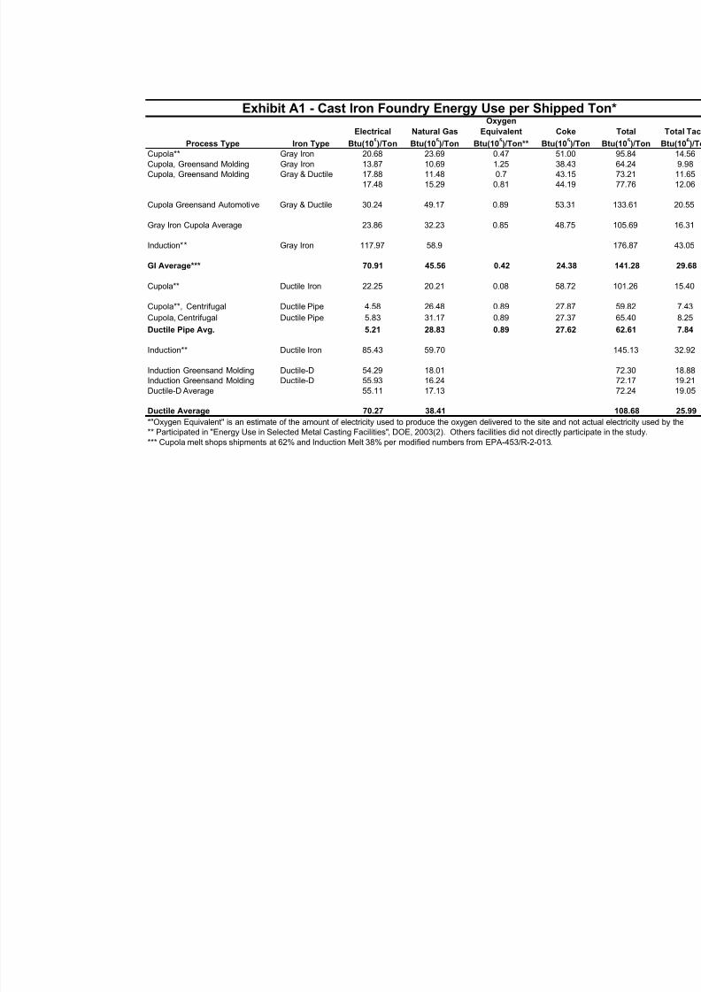
8/13/2019 Doebestpractice Casting
http://slidepdf.com/reader/full/doebestpractice-casting 99/116
Exhibit A1 - Cast Iron Foundry Energy Use per Shipped
Process Type
Cupola**Cupola, Greensand MoldingCupola, Greensand Molding
Iron Type
Gray IronGray IronGray & Ductile
ElectricalBtu(10
5)/Ton
20.6813.8717.8817.48
Natural GasBtu(10
5)/Ton
23.6910.6911.4815.29
Oxygen
EquivalentBtu(10
5)/Ton**
0.471.250.7
0.81
CokeBtu(10
5)/To
51.0038.4343.1544.19
Cupola Greensand Automotive Gray & Ductile 30.24 49.17 0.89 53.31
Gray Iron Cupola Average 23.86 32.23 0.85 48.75
Induction** Gray Iron 117.97 58.9
GI Average*** 70.91 45.56 0.42 24.38
Cupola** Ductile Iron 22.25 20.21 0.08 58.72
Cupola**, Centrifugal
Cupola, Centrifugal
Ductile Pipe Avg.
Ductile Pipe
Ductile Pipe
4.58
5.83
5.21
26.48
31.17
28.83
0.89
0.89
0.89
27.87
27.37
27.62
Induction** Ductile Iron 85.43 59.70
Induction Greensand MoldingInduction Greensand MoldingDuctile-D Average
Ductile-DDuctile-D
54.2955.9355.11
18.0116.2417.13
Ductile Average 70.27 38.41
*"Oxygen Equivalent" is an estimate of the amount of electricity used to produce the oxygen delivered to the site and not a** Participated in "Energy Use in Selected Metal Casting Facilities", DOE, 2003(2). Others facilities did not directly partici*** Cupola melt shops shipments at 62% and Induction Melt 38% per modified numbers from EPA-453/R-2-013.
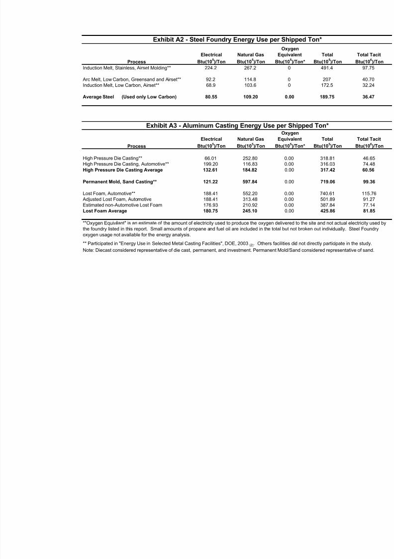
8/13/2019 Doebestpractice Casting
http://slidepdf.com/reader/full/doebestpractice-casting 100/116
Exhibit A2 - Steel Foundry Energy Use per Shipped Ton*
Oxygen
Electrical Natural Gas Equivalent Tot
Btu(105)/Ton Btu(10
5)/Ton Btu(10
5)/Ton* Btu(10
5Process
Induction Melt, Stainless, Airset Molding** 224.2 267.2 0 491
Arc Melt, Low Carbon, Greensand and Airset** 92.2 114.8 0 20Induction Melt, Low Carbon, Airset** 68.9 103.6 0 172
Average Steel (Used only Low Carbon) 80.55 109.20 0.00 189.
Exhibit A3 - Aluminum Casting Energy Use per Shipped Ton*Oxygen
Electrical Natural Gas Equivalent Tot
Process Btu(105)/Ton Btu(10
5)/Ton Btu(10
5)/Ton* Btu(10
5
High Pressure Die Casting** 66.01 252.80 0.00 318.High Pressure Die Casting, Automotive** 199.20 116.83 0.00 316High Pressure Die Casting Average 132.61 184.82 0.00 317.
Permanent Mold, Sand Casting** 121.22 597.84 0.00 719.
Lost Foam, Automotive** 188.41 552.20 0.00 740. Adjusted Lost Foam, Automotive 188.41 313.48 0.00 501Estimated non-Automotive Lost Foam 176.93 210.92 0.00 387Lost Foam Average 180.75 245.10 0.00 425.
*"Oxygen Equivilant" is an estimate of the amount of electricity used to produce the oxygen delivered to the site and nthe foundry listed in this report. Small amounts of propane and fuel oil are included in the total but not broken out indoxygen usage not available for the energy analysis.
** Participated in "Energy Use in Selected Metal Casting Facilities", DOE, 2003(2). Others facilities did not directly pa
Note: Diecast considered representative of die cast, permanent, and investment. Permanent Mold/Sand considered r
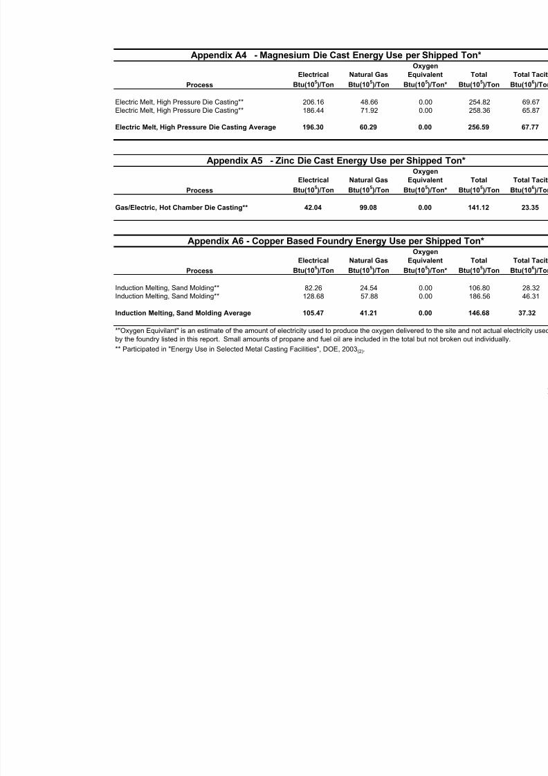
8/13/2019 Doebestpractice Casting
http://slidepdf.com/reader/full/doebestpractice-casting 101/116
Appendix A4 - Magnesium Die Cast Energy Use per ShippedOxygen
Electrical Natural Gas Equivalent
Process Btu(105)/Ton Btu(10
5)/Ton Btu(10
5)/Ton*
Electric Melt, High Pressure Die Casting** 206.16 48.66 0.00 Electric Melt, High Pressure Die Casting** 186.44 71.92 0.00
Electric Melt, High Pressure Die Casting Average 196.30 60.29 0.00
Appendix A5 - Zinc Die Cast Energy Use per Shipped TonOxygen
Electrical Natural Gas Equivalent
Process Btu(105)/Ton Btu(10
5)/Ton Btu(10
5)/Ton*
Gas/Electric, Hot Chamber Die Casting** 42.04 99.08 0.00
Appendix A6 - Copper Based Foundry Energy Use per ShippedOxygen
Electrical Natural Gas Equivalent
Process Btu(105)/Ton Btu(10
5)/Ton Btu(10
5)/Ton*
Induction Melting, Sand Molding** 82.26 24.54 0.00 Induction Melting, Sand Molding** 128.68 57.88 0.00
Induction Melting, Sand Molding Average 105.47 41.21 0.00
*"Oxygen Equivilant" is an estimate of the amount of electricity used to produce the oxygen delivered to the site aby the foundry listed in this report. Small amounts of propane and fuel oil are included in the total but not broken
** Participated in "Energy Use in Selected Metal Casting Facilities", DOE, 2003(2).
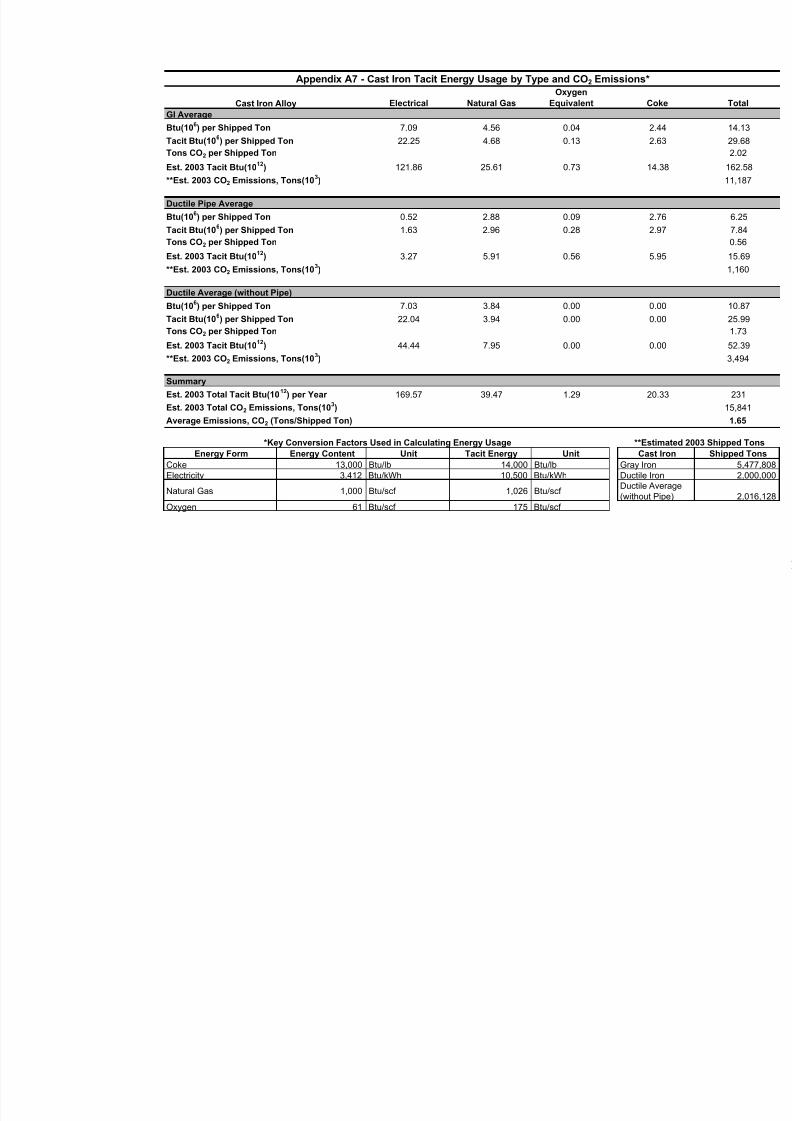
8/13/2019 Doebestpractice Casting
http://slidepdf.com/reader/full/doebestpractice-casting 102/116
Appendix A7 - Cast Iron Tacit Energy Usage by Type and CO2 Emissions*Oxygen
Cast Iron Alloy Electrical Natural Gas Equivalent Cok
GI Average
Btu(106) per Shipped Ton 7.09 4.56 0.04 2.44
Tacit Btu(106) per Shipped Ton 22.25 4.68 0.13 2.63
Tons CO2 per Shipped Ton
Est. 2003 Tacit Btu(1012
) 121.86 25.61 0.73 14.3
**Est. 2003 CO2 Emissions, Tons(103)
Ductile Pipe Average
Btu(106) per Shipped Ton 0.52 2.88 0.09 2.76
Tacit Btu(106) per Shipped Ton 1.63 2.96 0.28 2.97
Tons CO2 per Shipped Ton
Est. 2003 Tacit Btu(1012) 3.27 5.91 0.56 5.95
**Est. 2003 CO2 Emissions, Tons(103)
Ductile Average (without Pipe)
Btu(106) per Shipped Ton 7.03 3.84 0.00 0.00
Tacit Btu(106) per Shipped Ton 22.04 3.94 0.00 0.00
Tons CO2 per Shipped Ton
Est. 2003 Tacit Btu(1012
) 44.44 7.95 0.00 0.00
**Est. 2003 CO2 Emissions, Tons(103)
Summary
Est. 2003 Total Tacit Btu(1012) per Year 169.57 39.47 1.29 20.3
Est. 2003 Total CO2 Emissions, Tons(103)
Average Emissions, CO2 (Tons/Shipped Ton)
**Estim*Key Conversion Factors Used in Calculating Energy Usage
Energy Form Energy Content Unit Tacit Energy UnitCoke 13,000 Btu/lb 14,000 Btu/lbElectricity 3,412 Btu/kWh 10,500 Btu/kWh
Natural Gas 1,000 Btu/scf 1,026 Btu/scf
Oxygen 61 Btu/scf 175 Btu/scf
Cast IGray Iron Ductile IronDuctile Ave(without Pi
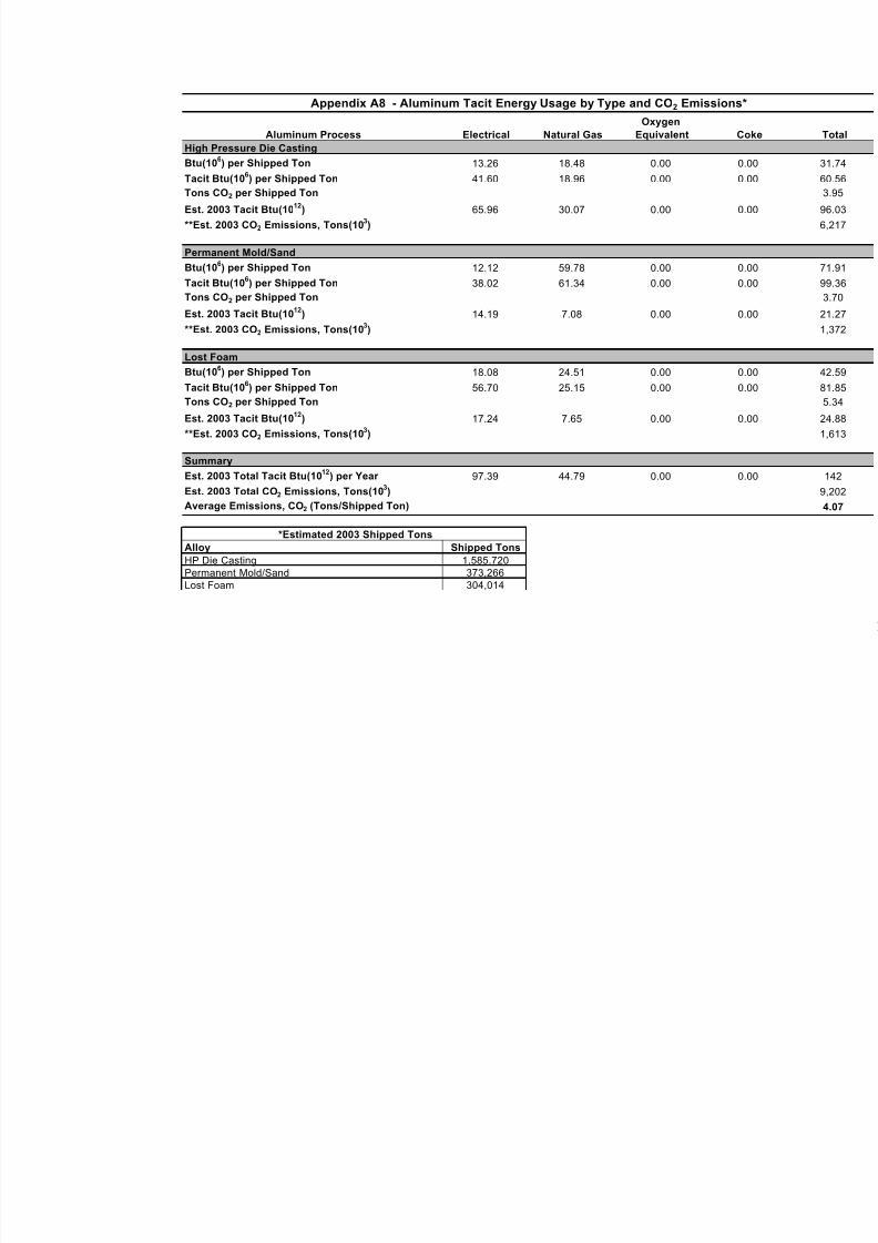
8/13/2019 Doebestpractice Casting
http://slidepdf.com/reader/full/doebestpractice-casting 103/116
Appendix A8 - Aluminum Tacit Energy Usage by Type and CO2 Emission
Oxygen
Aluminum Process Electrical Natural Gas Equivalent
High Pressure Die Casting
Btu(10
6
) per Shipped Ton 13.26 18.48 0.00 Tacit Btu(10
6) per Shipped Ton 41.60 18.96 0.00
Tons CO2 per Shipped Ton
Est. 2003 Tacit Btu(1012
) 65.96 30.07 0.00
**Est. 2003 CO2 Emissions, Tons(103)
Permanent Mold/Sand
Btu(106) per Shipped Ton 12.12 59.78 0.00
Tacit Btu(106) per Shipped Ton 38.02 61.34 0.00
Tons CO2 per Shipped Ton
Est. 2003 Tacit Btu(1012
) 14.19 7.08 0.00
**Est. 2003 CO2 Emissions, Tons(10
3
)
Lost Foam
Btu(106) per Shipped Ton 18.08 24.51 0.00
Tacit Btu(106) per Shipped Ton 56.70 25.15 0.00
Tons CO2 per Shipped Ton
Est. 2003 Tacit Btu(1012
) 17.24 7.65 0.00
**Est. 2003 CO2 Emissions, Tons(103)
Summary
Est. 2003 Total Tacit Btu(1012
) per Year 97.39 44.79 0.00
Est. 2003 Total CO2 Emissions, Tons(103)
Average Emissions, CO2 (Tons/Shipped Ton)
*Estimated 2003 Shipped Tons
Alloy Shipped Tons
HP Die Casting 1,585,720Permanent Mold/Sand 373,266Lost Foam 304,014
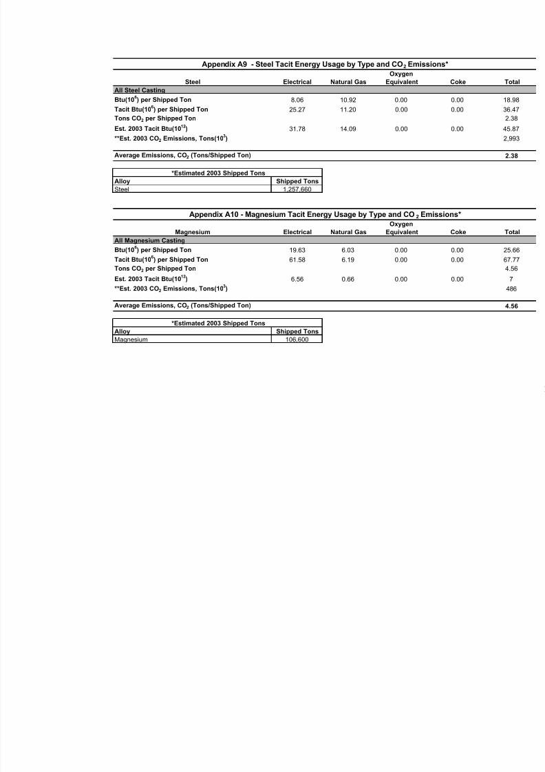
8/13/2019 Doebestpractice Casting
http://slidepdf.com/reader/full/doebestpractice-casting 104/116
Appendix A9 - Steel Tacit Energy Usage by Type and CO2 Emissions*Oxygen
Steel Electrical Natural Gas Equivalent Co
All Steel Casting
Btu(106) per Shipped Ton 8.06 10.92 0.00 0
Tacit Btu(106) per Shipped Ton 25.27 11.20 0.00 0
Tons CO2 per Shipped Ton
Est. 2003 Tacit Btu(1012) 31.78 14.09 0.00 0
**Est. 2003 CO2 Emissions, Tons(103)
Average Emissions, CO2 (Tons/Shipped Ton)
*Estimated 2003 Shipped Tons
Alloy Shipped Tons
Steel 1,257,660
Appendix A10 - Magnesium Tacit Energy Usage by Type and CO2 EmissionsOxygen
Magnesium Electrical Natural Gas Equivalent Co
All Magnesium Casting
Btu(106) per Shipped Ton 19.63 6.03 0.00 0
Tacit Btu(106) per Shipped Ton 61.58 6.19 0.00 0
Tons CO2 per Shipped Ton
Est. 2003 Tacit Btu(1012
) 6.56 0.66 0.00 0
**Est. 2003 CO2 Emissions, Tons(103)
Average Emissions, CO2 (Tons/Shipped Ton)
*Estimated 2003 Shipped Tons
Alloy Shipped Tons
Magnesium 106,600
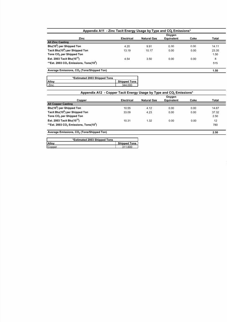
8/13/2019 Doebestpractice Casting
http://slidepdf.com/reader/full/doebestpractice-casting 105/116
Appendix A11 - Zinc Tacit Energy Usage by Type and CO2 Emissions*
Oxygen
Zinc Electrical Natural Gas Equivalent
All Zinc CastingBtu(10
6) per Shipped Ton 4.20 9.91 0.00
Tacit Btu(106) per Shipped Ton 13.19 10.17 0.00
Tons CO2 per Shipped Ton
Est. 2003 Tacit Btu(1012) 4.54 3.50 0.00
**Est. 2003 CO2 Emissions, Tons(103)
Average Emissions, CO2 (Tons/Shipped Ton)
*Estimated 2003 Shipped Tons
Alloy Shipped Tons
Zinc 344,000
Appendix A12 - Copper Tacit Energy Usage by Type and CO2 Emission
Oxygen
Copper Electrical Natural Gas Equivalent
All Copper Casting
Btu(106) per Shipped Ton 10.55 4.12 0.00
Tacit Btu(106) per Shipped Ton 33.09 4.23 0.00
Tons CO2 per Shipped Ton
Est. 2003 Tacit Btu(1012
) 10.31 1.32 0.00
**Est. 2003 CO2 Emissions, Tons(103)
Average Emissions, CO2 (Tons/Shipped Ton)
*Estimated 2003 Shipped Tons
Alloy Shipped Tons
Copper 311,600

8/13/2019 Doebestpractice Casting
http://slidepdf.com/reader/full/doebestpractice-casting 106/116
APPENDIX “B”
105
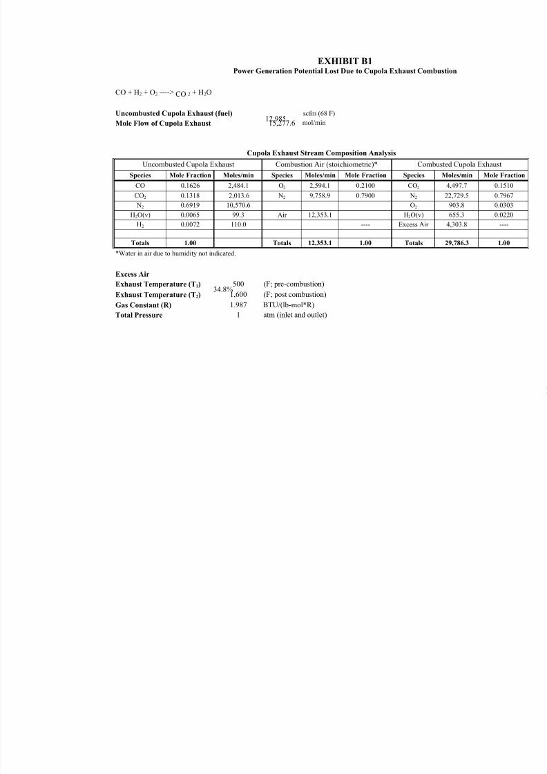
8/13/2019 Doebestpractice Casting
http://slidepdf.com/reader/full/doebestpractice-casting 107/116
EXHIBIT B1Power Generation Potential Lost Due to Cupola Exhaust Combustion
CO + H2 + O2 ----> CO 2 + H2O
Uncombusted Cupola Exhaust (fuel) 12,985
scfm (68 F)
Mole Flow of Cupola Exhaust 15,277.6 mol/min
Cupola Exhaust Stream Composition Analysis
Uncombusted Cupola Exhaust Combustion Air (stoichiometric)* Combusted C
Species Mole Fraction Moles/min Species Moles/min Mole Fraction Species Moles
CO 0.1626 2,484.1 O2 2,594.1 0.2100 CO2 4,49
CO2 0.1318 2,013.6 N2 9,758.9 0.7900 N2 22,72
N2 0.6919 10,570.6 O2 903H2O(v) 0.0065 99.3 Air 12,353.1 H2O(v) 655
H2 0.0072 110.0 ---- Excess Air 4,30
Totals 1.00 Totals 12,353.1 1.00 Totals 29,7
*Water in air due to humidity not indicated.
Excess Air
34.8%Exhaust Temperature (T1) 500 (F; pre-combustion)
Exhaust Temperature (T2) 1,600 (F; post combustion)
Gas Constant (R) 1.987 BTU/(lb-mol*R)
Total Pressure 1 atm (inlet and outlet)
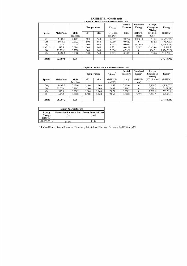
8/13/2019 Doebestpractice Casting
http://slidepdf.com/reader/full/doebestpractice-casting 108/116
EXHIBIT B1 (Continued)Cupola Exhaust - Precombustion Stream Data
Species Moles/min Mole
Fraction
Temperature Cpmean*
(BTU/(lb-
mole*F))
Partial
Pressure
(atm)
Standard
Exergy
(BTU/lb-
mole)
Exergy
Change o
Mixing
(BTU/lb
mole)
(F) (R)
CO 2,484.1 0.0767 500 960 7.079 0.0767 110,614 -1,944.5CO2 2,013.6 0.0622 500 960 9.909 0.0622 0 -1,852.2H2 110.0 0.0034 500 960 6.915 0.0034 102,042 -5,282.7
H2O (v) 545.3 0.0168 500 960 8.271 0.0168 3,697 -3,426.4
N2 23,729.5 0.7328 500 960 7.036 0.7328 0 454.3
O2 3,497.9 0.1080 500 960 7.315 0.1080 0 -1,553.6
Totals 32,380.5 1.00
Cupola Exhaust - Post Combustion Stream Data
Species Moles/min Mole
Fraction
Temperature Cpmean*
(BTU/(lb-mol*F))
PartialPressure
(atm)
StandardExergy
(BTU/lb-mol)
ExergyChange o
Mixing
(BTU/lb-m(F) (R)
CO2 4,497.7 0.1510 1,600 2,060 11.67 0.1510 0 7,350.2
N2 23,729.5 0.7967 1,600 2,060 7.405 0.7967 0 5,699.4O2 903.8 0.0303 1,600 2,060 7.871 0.0303 0 2,592.9
H2O (v) 655.3 0.0220 1,600 2,060 9.060 0.0220 3,697 3,204.5
Totals 29,786.3 1.00
Exergy Analysis Results
Exergy
Change
BTU/(hr)
Generation Potential Lost
(%)Power Potential Lost
(kW)
-14,165,671.438.0%
4,149
* Richard Felder, Ronald Rousseau, Elementary Principles of Chemical Processes, 2nd Edition, p351
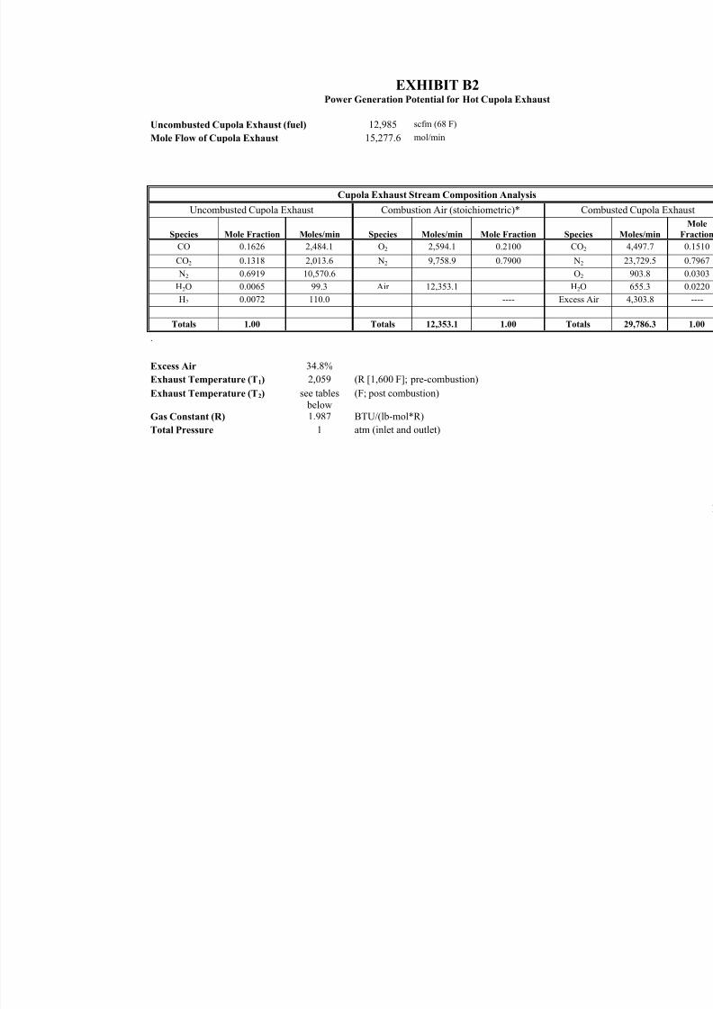
8/13/2019 Doebestpractice Casting
http://slidepdf.com/reader/full/doebestpractice-casting 109/116
EXHIBIT B2Power Generation Potential for Hot Cupola Exhaust
Uncombusted Cupola Exhaust (fuel) 12,985 scfm (68 F)
Mole Flow of Cupola Exhaust 15,277.6 mol/min
Cupola Exhaust Stream Composition Analysis
Uncombusted Cupola Exhaust Combustion Air (stoichiometric)* Com
Species Mole Fraction Moles/min Species Moles/min Mole Fraction Species
CO 0.1626 2,484.1 O2 2,594.1 0.2100 CO2
CO2 0.1318 2,013.6 N2 9,758.9 0.7900 N2
N2 0.6919 10,570.6 O2
H2O 0.0065 99.3 Air 12,353.1 H2O
H2 0.0072 110.0 ---- Excess Ai
Totals 1.00 Totals 12,353.1 1.00 Totals
.
Excess Air
Exhaust Temperature (T1)
Exhaust Temperature (T2)
Gas Constant (R)
Total Pressure
34.8%
2,059
see tables
below1.987
1
(R [1,600 F]; pre-combustion)
(F; post combustion)
BTU/(lb-mol*R)
atm (inlet and outlet)
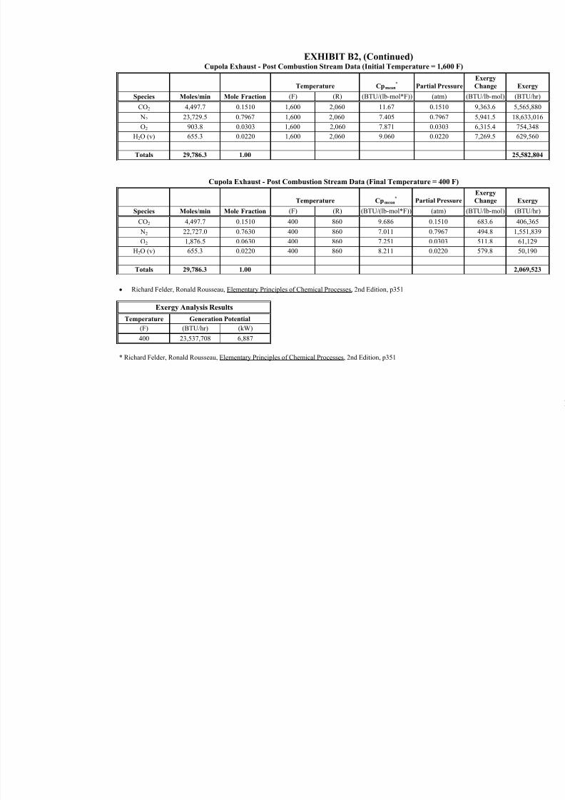
8/13/2019 Doebestpractice Casting
http://slidepdf.com/reader/full/doebestpractice-casting 110/116
EXHIBIT B2, (Continued)Cupola Exhaust - Post Combustion Stream Data (Initial Temperature = 1,600 F)
Temperature Cpmean*
Partial Pressure
Species Moles/min Mole Fraction (F) (R) (BTU/(lb-mol*F)) (atm) (B
CO2 4,497.7 0.1510 1,600 2,060 11.67 0.1510 N2 23,729.5 0.7967 1,600 2,060 7.405 0.7967
O2 903.8 0.0303 1,600 2,060 7.871 0.0303
H2O (v) 655.3 0.0220 1,600 2,060 9.060 0.0220
Totals 29,786.3 1.00
Cupola Exhaust - Post Combustion Stream Data (Final Temperature = 400 F)
Temperature Cpmean*
Partial Pressure
Species Moles/min Mole Fraction (F) (R) (BTU/(lb-mol*F)) (atm) (B
CO2 4,497.7 0.1510 400 860 9.686 0.1510
N2 22,727.0 0.7630 400 860 7.011 0.7967
O2 1,876.5 0.0630 400 860 7.251 0.0303
H2O (v) 655.3 0.0220 400 860 8.211 0.0220
Totals 29,786.3 1.00
• Richard Felder, Ronald Rousseau, Elementary Principles of Chemical Processes, 2nd Edition, p351
Exergy Analysis Results
Temperature Generation Potential
(F) (BTU/hr) (kW)
400 23,537,708 6,887
* Richard Felder, Ronald Rousseau, Elementary Principles of Chemical Processes, 2nd Edition, p351
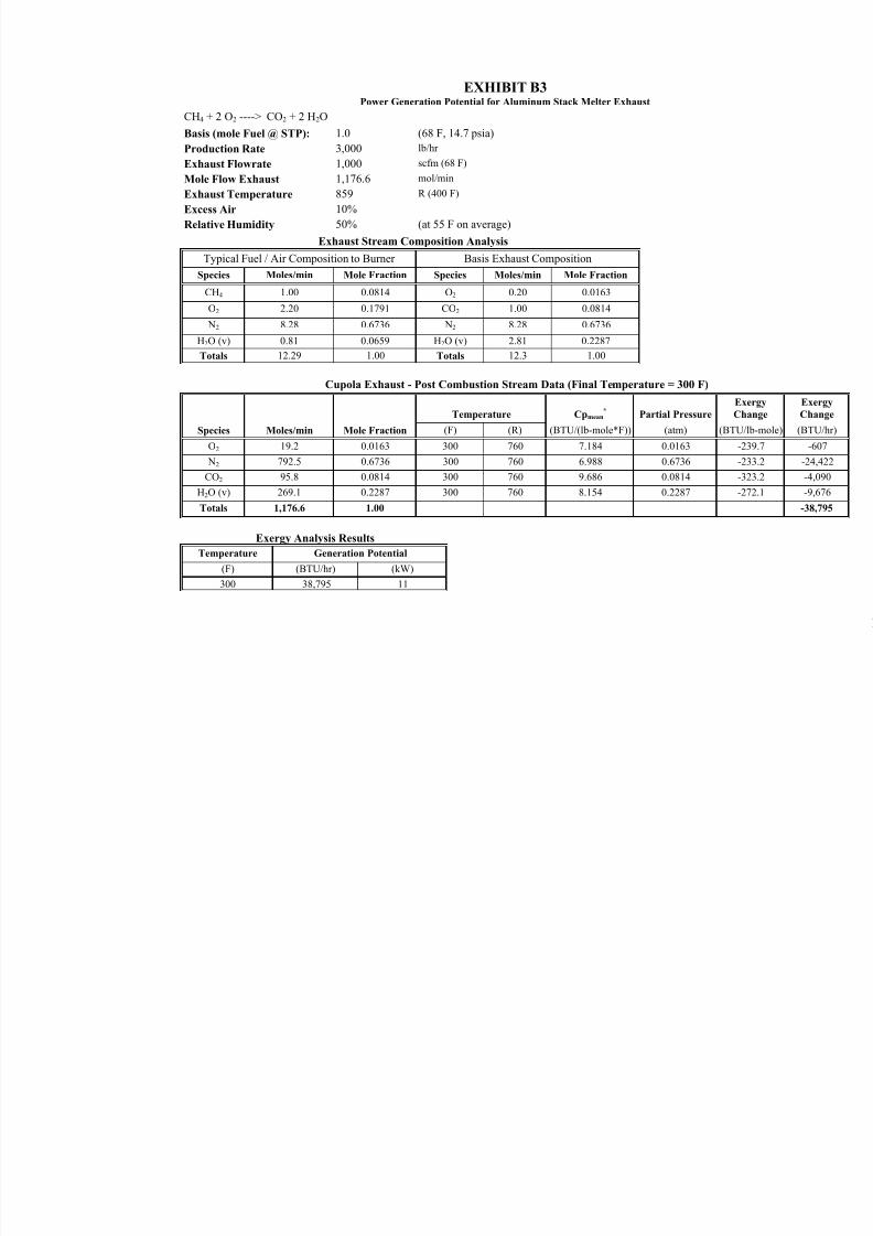
8/13/2019 Doebestpractice Casting
http://slidepdf.com/reader/full/doebestpractice-casting 111/116
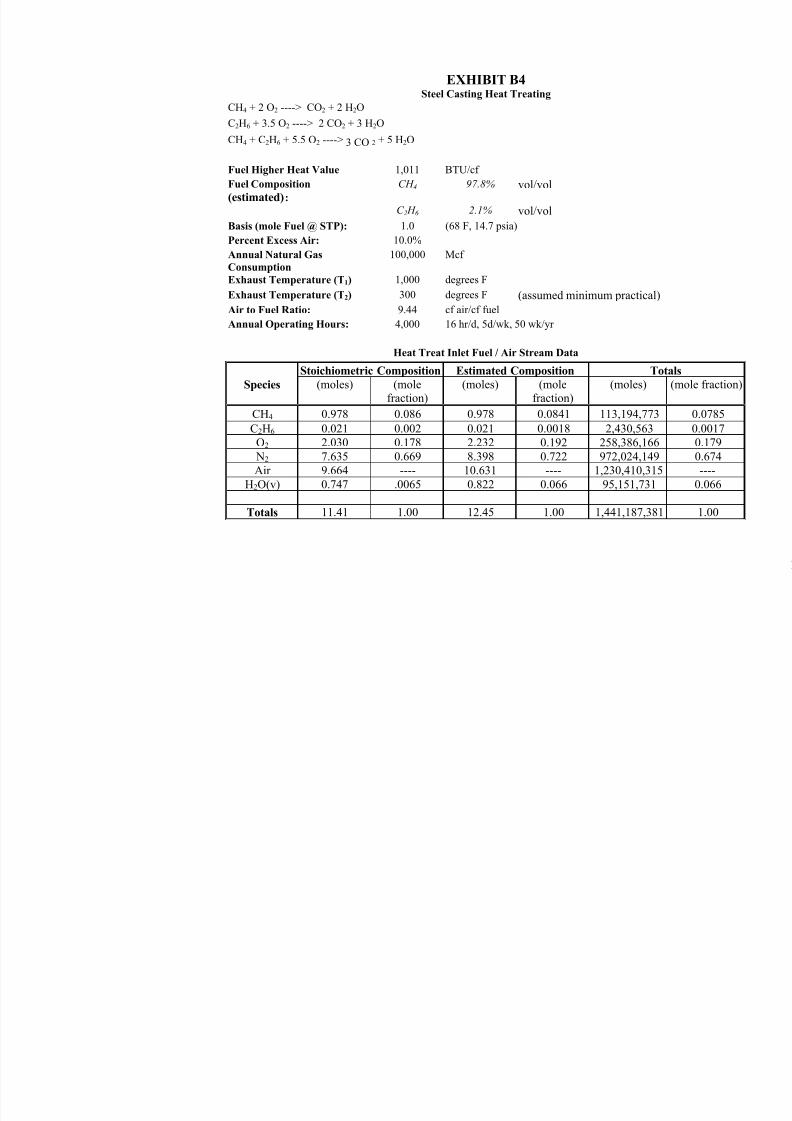
8/13/2019 Doebestpractice Casting
http://slidepdf.com/reader/full/doebestpractice-casting 112/116
EXHIBIT B4Steel Casting Heat Treating
CH4 + 2 O2 ----> CO2 + 2 H2O
C2H6 + 3.5 O2 ----> 2 CO2 + 3 H2O
CH4 + C2H6 + 5.5 O2 ----> 3 CO 2 + 5 H2O
Fuel Higher Heat Value 1,011 BTU/cf
Fuel Composition
(estimated):
CH 4 97.8% vol/vol
C 2 H 6 2.1% vol/vol
Basis (mole Fuel @ STP): 1.0 (68 F, 14.7 psia)
Percent Excess Air: 10.0%
Annual Natural Gas 100,000 McfConsumption
Exhaust Temperature (T1) 1,000 degrees F
Exhaust Temperature (T2) 300 degrees F (assumed minimum practical)
Air to Fuel Ratio: 9.44 cf air/cf fuel
Annual Operating Hours: 4,000 16 hr/d, 5d/wk, 50 wk/yr
Heat Treat Inlet Fuel / Air Stream Data
Species
Stoichiometric Composition Estimated Composition To
(moles) (molefraction)
(moles) (molefraction)
(moles)
CH4 0.978 0.086 0.978 0.0841 113,194,773
C2H6 0.021 0.002 0.021 0.0018 2,430,563 O2 2.030 0.178 2.232 0.192 258,386,166
N2 7.635 0.669 8.398 0.722 972,024,149 Air 9.664 ---- 10.631 ---- 1,230,410,315
H2O(v) 0.747 .0065 0.822 0.066 95,151,731
Totals 11.41 1.00 12.45 1.00 1,441,187,381
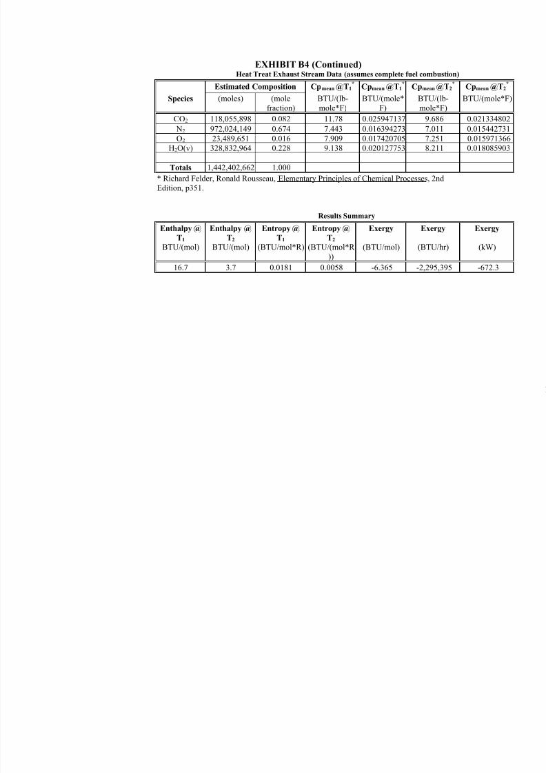
8/13/2019 Doebestpractice Casting
http://slidepdf.com/reader/full/doebestpractice-casting 113/116
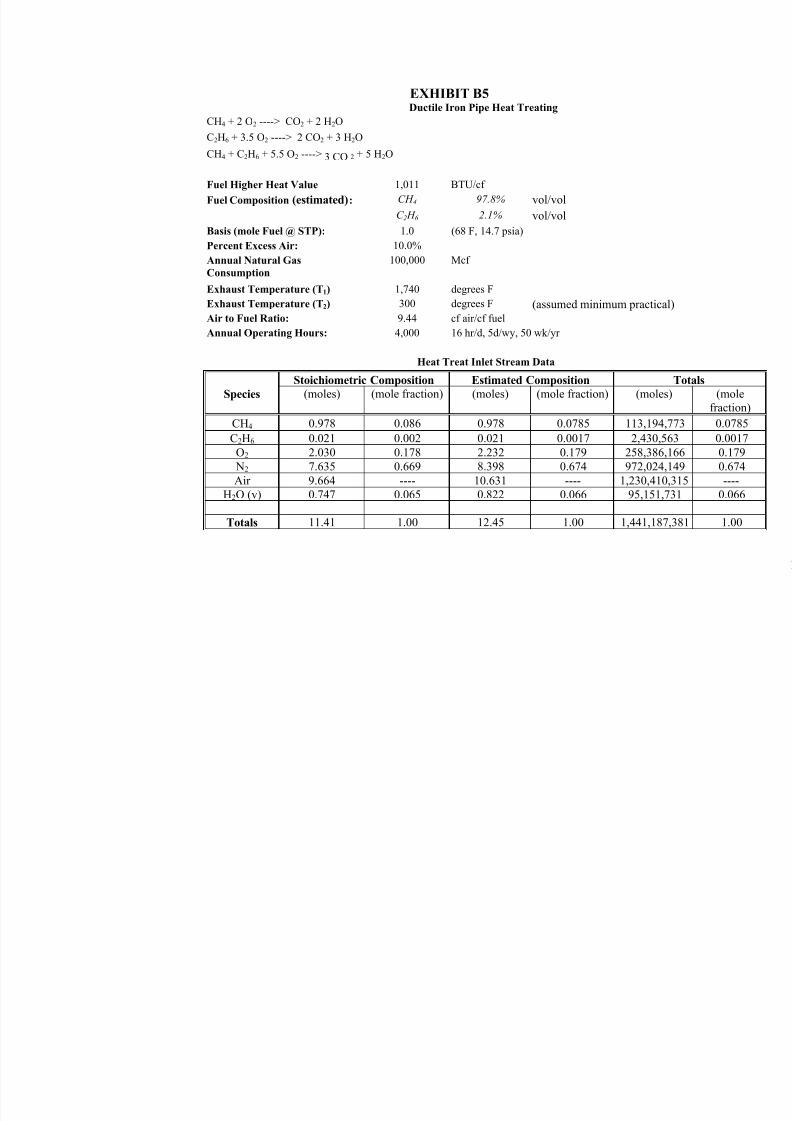
8/13/2019 Doebestpractice Casting
http://slidepdf.com/reader/full/doebestpractice-casting 114/116
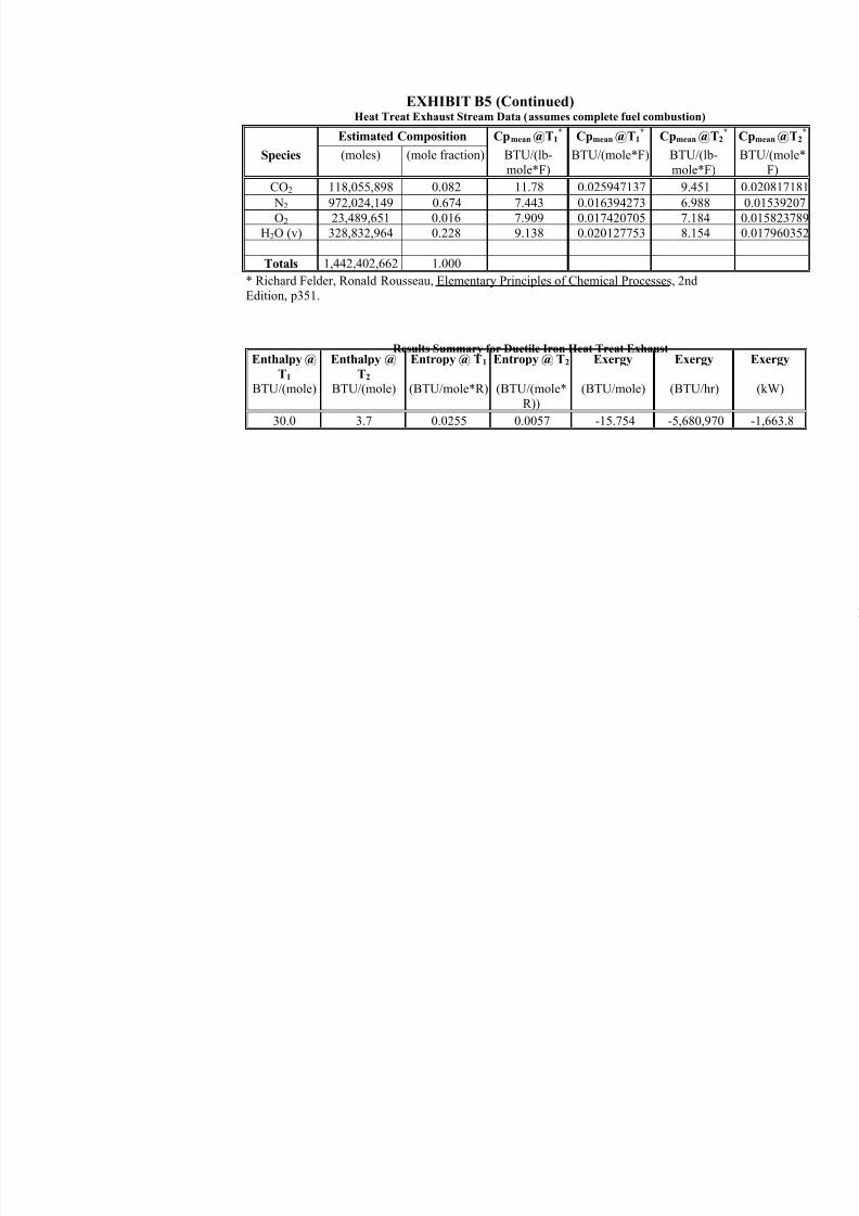
8/13/2019 Doebestpractice Casting
http://slidepdf.com/reader/full/doebestpractice-casting 115/116
EXHIBIT B5 (Continued)Heat Treat Exhaust Stream Data (assumes complete fuel combustion)
Species
Estimated Composition Cpmean @T1*
BTU/(lb-mole*F)
Cpmean @T1*
BTU/(mole*F)
Cpmean @T
BTU/(lb-mole*F)
(moles) (mole fraction)
CO2 118,055,898 0.082 11.78 0.025947137 9.451
N2 972,024,149 0.674 7.443 0.016394273 6.988
O2 23,489,651 0.016 7.909 0.017420705 7.184 H2O (v) 328,832,964 0.228 9.138 0.020127753 8.154
Totals 1,442,402,662 1.000
* Richard Felder, Ronald Rousseau, Elementary Principles of Chemical Processes, 2ndEdition, p351.
Results Summary for Ductile Iron Heat Treat ExhaustEnthalpy @
T1
BTU/(mole)
Enthalpy @
T2
BTU/(mole)
Entropy @ T1
(BTU/mole*R)
Entropy @ T2
(BTU/(mole*R))
Exergy
(BTU/mole)
Exergy
(BTU/hr)
30.0 3.7 0.0255 0.0057 -15.754 -5,680,970

8/13/2019 Doebestpractice Casting
http://slidepdf.com/reader/full/doebestpractice-casting 116/116