Embed Size (px)
Citation preview
EN
9000-610-45/30
2009
/03
Dürr Dental Compressors with membrane-drying unit
Installation and Operating Instructions

EN
2009/03� 3
Contents
Important Information1. General� �������������������������������������������������� 4
1�1� Note�on�Conformity� �������������������������� 41�2� General�Notes� ���������������������������������� 41�3� Appliance�disposal����������������������������� 41�4� Correct�Usage� ���������������������������������� 41�5� Incorrect�Usage��������������������������������� 51�6� Use�of�peripheral�units� ���������������������� 5
2. Safety������������������������������������������������������� 52�1� General�Safety�Notes������������������������� 52�2� Safety�notes�concerning�protection�
from�electrical�current������������������������� 53. Warnings and Symbols ��������������������������� 6
3�1� Model�identification�plates� ���������������� 64. Delivery Contents� ���������������������������������� 7
4�1� Special�accessories��������������������������� 74�2� Disposable�materials� ������������������������ 7
5. Technical Data����������������������������������������� 86. Functional layout����������������������������������� 10
6�1� Compressor�with�dry�air�unit������������� 106�2� Compressor�without�a�dry�air�unit�� �� 10
7. Functional Description� ������������������������ 117�1� Compressor�with�dry�air�unit������������� 117�2� Compressor�without�a�dry�air�unit����� 11
Installation8. Transport and storage conditions� ������ 139. Set-up and initial use� �������������������������� 13
9�1� Ambient�conditions��������������������������� 139�2� Compressed�air�connections� ���������� 149�3� Electrical�connections����������������������� 159�4� Switch�on�compressor��������������������� 159�5� Motor�protection�switch�settings������� 169�6� Check�safety�valve�settings��������������� 169�7� Check�pressure�switch�and�reset�
where�deviant����������������������������������� 169�8� Drain�off�condensated�water������������� 17
10. Circuit diagrams� ���������������������������������� 1810�1� Model�type�1/N/PE�AC�230V����������� 1810�2� Model�type�3/N/PE�AC�400V����������� 1810�3� Model�type�3/N/PE�AC�400V,�
2�aggregates,�Duo�Tandem������������� 1910�4� Model�type�3/N/PE�AC�400V,�2�
aggregates,�Quattro�Tandem����������� 1910�5� Model�type�3/N/PE�AC�230V,�2�
aggregates,�Quattro�Tandem����������� 20
Use11. Operation����������������������������������������������� 21
11�1� Turning�the�compressor�On�/�Off����� 2112. Maintenance intervals – Operator /
Service Technician� ������������������������������ 2213. Maintenance� ���������������������������������������� 22
13�1� Pressure�reducer����������������������������� 2213�2� Setting�the�pressure�reducer����������� 2313�3� Drain�off�condensated�water����������� 2313�4� Check�safety�valve�settings������������� 2313�5� Changing�the�filter��������������������������� 2413�6� Change�vibration�dampers� ������������ 25
14. Deactivation������������������������������������������� 25
Troubleshooting15. Tips for Operators and Technicians����� 2616. Tips for Technicians� ���������������������������� 27

EN
4� 2009/03
all�good�faith��Dürr�Dental�deny�any�liability�for�inaccurate�translation�and�in�the�case�of�any�doubts�the�user�should�contact�Dürr�Dental�or�their�supplier��The�enclosed�German�version�of�the�Installation�and�Operating�Instructions�is�the�original�
•�Any�reprinting�of�the�technical�documentation,�in�whole�or�in�part,�is�subject�to�prior�approval�of�Dürr�Dental�being�given�in�writing�
•�Retain�the�packaging�for�possible�return�of�the�product�to�the�manufacturers��Ensure�that�the�packaging�is�kept�out�of�the�reach�of�children��Only�the�original�packaging�provides�adequate�protection�during�transport�of�the�unit��Should�return�of�the�product�to�the�manufacturers�be�necessary�during�the�guarantee�period,�Dürr�Dental�accepts�no�responsibility�for�damage�occurring�during�transport�where�the�original�packaging�was�not�used!
1.3 Appliance disposalThe�EU-guidelines�2002/96/EG�-�WEEE�(Waste�Electric�and�Electronic�Equipment)�of�27th�January�2003�and�their�latest�adoption�into�nati-onal�law�state�that�dental�products�must�be�tre-ated�as�under�the�said�guidelines�and,�within�the�European�Union,�must�be�disposed�of�as�spe-cial�waste��Any�questions�concerning�the�dispo-sal�of�these�products�can�be�addressed�either�to�Dürr�Dental�or�to�your�secialist�dental�dealer�
1.4 Correct UsageThe�compressor�is�designed�for�supplying�com-pressed�air�for�the�operation�of�dental�equip-ment�or�similar�applications�Installation�inside�a�medical�supply�equipment:�During�development�and�construction�of�the�compressor�all�legal�and�technical�requirements�concerning�medical�products�were�taken�into�condideration�where�possible��This�appliance�may�be�installed�in�facilities�providing�medical�care��If�this�unit�is�installed�in�medical�supply�equipment,�then�during�installation�all�require-ments�governing�medical�gas�supply�units�as�well�as�all�relevant�standards�and�laws,�especial-ly�the�laws�concerning�medication�and�medical�supplies,�must�be�strictly�observed�Any�usage�above�and�beyond�that�explicitly�mentioned�in�the�installation�and�operating�in-structions�is�deemed�to�be�incorrect�usage��The�manufacturer�cannot�be�held�liable�for�any�da-mage�resulting�from�incorrect�usage��The�opera-tor�/�user�bears�all�risks�
Important Information
1. General1.1 Note on ConformityThis�product�has�been�designed�and�produced�according�to�the�relevant�directives�conserning�such�appliances�under�the�European�Union�and�has�undergone�conformity�testing�and�has�been�found�to�adhere�to�all�requirements�covered�by�these�directives,�see�Declaration�of�Conformity�
1.2 General Notes•�These�Installation�and�Operating�Instructions�
form�an�integral�part�of�the�unit��They�must�be�kept�close�to�the�unit�at�all�times��Precise�ob-servance�of�these�instructions�is�a�precondi-tion�for�use�of�the�unit�for�the�intended�purpo-se�and�for�its�correct�operation��New�person-nel�must�be�made�aware�of�the�contents,�and�they�should�be�passed�on�to�future�operating�staff�
•�Safety�for�the�operator�as�well�as�trouble-free�operation�of�the�unit�are�only�ensured�if�use�is�made�of�original�equipment�parts��Only�acces-sories�which�are�expressly�mentioned�in�the�Installation�and�Operating�Instructions�may�be�connected�or�those�recommended�explicitly�by�Dürr�Dental��If�other�accessories�are�used�with�this�appliance,�Dürr�Dental�cannot�gua-rantee�safe�operation�or�proper�functioning��No�liability�on�the�part�of�the�manufacturer�will�be�accepted�in�the�case�that�damage�arises�through�the�use�of�non-approved�accessories�
•�Dürr�Dental�are�only�responsible�for�the�equip-ment�with�regard�to�safety,�reliability�and�pro-per�functioning�where�assembly,�resettings,�changes�or�modifications,�extensions�and�re-pairs�have�been�carried�out�by�Dürr�Dental�or�an�agency�authorized�by�Dürr�Dental�and�if�the�equipment�is�used�in�conformity�with�the�Installation�and�Operating�Instructions�
•�These�Installation�and�Operating�Instructions�conform�to�the�relevant�version�of�the�equip-ment�and�the�underlying�safety�standards�va-lid�at�the�time�of�going�to�press��All�switches,�processes,�trade�marks,�software�programs�and�appliances�named�in�this�document�are�registered�names�
•�This�translation�of�the�Installation�and�Operating�Instructions�has�been�carried�out�in�

EN
2009/03� 5
1.5 Incorrect Usage
This compressor is not to be opera-ted in operating theatres. The compressed air is not to be used for respiration appliances or for similar uses, e.g. those found in operating theatres.
1.6 Use of peripheral unitsAppliance�may�only�be�connected�together�when�absolutely�sure�that�the�safety�of�the�pati-ent,�operator�or�the�environment�will�not�be�endangered�in�any�way�whatsoever��Where�it�is�not�clear�from�the�documentation�ac-companying�any�device�that�it�is�safe�to�connect�to�another�appliance,�then�the�customer/opera-tor�must�establish,�e�g��by�contacting�the�ma-nufacturer�or�consulting�a�technical�expert,�that�the�necessary�safety�for�the�patient,�operator�or�the�environment�will�not�be�endangered�in�any�way�whatsoever�
2. Safety2.1 General Safety NotesThis�appliance�has�been�so�designed�by�Dürr�Dental�that�any�danger�in�operation�is�out�of�the�question�when�the�appliance�is�used�correctly���In�spite�of�this,�we�feel�it�is�our�duty�to�mention�the�following�safety�measures�in�order�to�pre-vent�any�possible�danger�•�When�operating�this�unit�then�all�local�and�na-
tional�regulations�must�be�strictly�observed,�e�g��Healthy�and�Safety�at�Work�regulations!�Converting�or�modifying�the�appliance�in�any�way�is�strictly�prohibited��In�such�cases,�any�and�all�guarantees�immediately�become�inva-lid��The�operation�of�modified�appliances�can�be�punishable�by�law��In�the�interests�of�trou-ble-free�operation�the�operator�is�responsible�for�observing�these�regulations�
•� Installation�must�be�carried�out�by�a�technical�expert�
•�Before�every�use�the�operator�must�check�the�functional�safety��and�the�condition�of�the�appliance�
•�The�operator�must�be�knowledgeable�in�the�operation�of�the�appliance�
•�The�product�is�not�designed�to�be�used�in�medical�treatment�areas�where�there�exists�the�danger�of�explosion��Areas�
where�explosions�could�occur�are�those�where�flammable�anesthetic�material,�skin�cleansers,�oxygen�and�skin�disinfectants�are�present��This�appliance�is�not�to�be�used�in�areas�where�the�atmosphere�could�cause�fire�
2.2 Safety notes concerning pro-tection from electrical current
•�This�appliance�may�only�be�operated�from�a�correctly�installed�power�outlet�
•�Before�connecting�to�the�electricity�supply�the�appliance�must�be�inspected�and�checked�that�the�supply�voltage�and�the�supply�fre-quency�correspond�to�that�of�the�local�electri-cal�supply�
•�Before�initial�use�and�start-up�the�appliance�and�all�supply�lines�must�be�checked�for�any�signs�of�damage��Damaged�cables,�plugs�and�sockets�must�be�replaced�before�use�
•�When�using�the�appliance�observe�all�the�rele-vant�electrical�safety�procedures�
EN
6� 2009/03
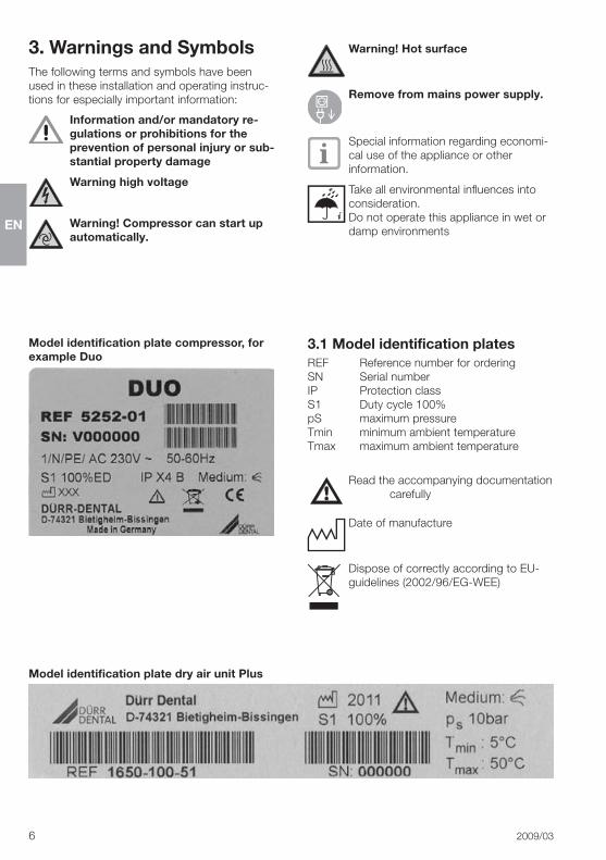
3. Warnings and Symbols The�following�terms�and�symbols�have�been�used�in�these�installation�and�operating�instruc-tions�for�especially�important�information:
Information and/or mandatory re-gulations or prohibitions for the prevention of personal injury or sub-stantial property damage
Warning high voltage
Warning! Compressor can start up automatically.
Model identification plate compressor, for example Duo
Model identification plate dry air unit Plus
Warning! Hot surface
Remove from mains power supply.
Special�information�regarding�economi-cal�use�of�the�appliance�or�other�information�
Take�all�environmental�influences�into�consideration��Do�not�operate�this�appliance�in�wet�or�damp�environments
3.1 Model identification platesREF� Reference�number�for�orderingSN� Serial�numberIP� Protection�classS1� Duty�cycle�100%pS� maximum�pressureTmin� minimum�ambient�temperatureTmax� maximum�ambient�temperature
Read�the�accompanying�documentation�carefully
Date�of�manufacture
Dispose�of�correctly�according�to�EU-guidelines�(2002/96/EG-WEE)

EN
2009/03� 7
4. Delivery ContentsInstallation�and�Operating�Instructions��������������� 9000-610-45/30Accessories ���������������������������������� 5410-002-00(incl���pressure�hoses�ø8x3x14,�length�2�m)
Only for compressors equipped with dry air units
Collector�tray �������������������������������� 3413-001-00
4.1 Special accessoriesThe�following�parts�are�special�accessories�and�must�be�ordered�separately�as�required��Order�as�necessary!
Wooden�cabinet�for�models��5150,�5152,�5170,�5172,�5250,�5252,�5270,�5272���������������� 5150-500-004152,�4252,�5352,�5450,�5452������ 4251-500-00Pressure�reducer���������������������������� 6040-992-00Stop�valve������������������������������������� 5150-983-00�Sterile�filter������������������������������������ 1640-981-00
4.2 Disposable materialsIntake�filter�for�compressorsPrimo,�Duo,�Trio,�Quattro,�Duo�Tandem�and�Quattro�Tandem �������� 0832-982-00Tornado ���������������������������������������� 5430-982-00
Dry�air�unitSintered�filter���������������������������������� 1650-101-00Fine�filter���������������������������������������� 1610-121-00Sterile�filter������������������������������������ 1640-981-00

EN
8� 2009/03
Model Primo5152-01a5150-01b
Duo5252-01a5250-01b
Duo5252-51a5250-51b
Trio5352-01a
Quattro5452-51a5450-51b
Voltage V 230 230 400 230 400
Frequency Hz 50�-�60 50�-�60 50�-�60 50 50�-�60
Current consumption at 8 bar A 4�3C�-�4�4C 6�3C�-�7�0C 3�1C�-�2�5C 8,6 4�4C�-�4�8C
Motor protection switch max. permitted settings recommended settings A
6,35�6C�-�4�4C
8,56�5C�-�7�6C
3,53�2C�-�2�5C
108,6
6,34�4C�-�5�0C
Rated power kW 0�80C�-�0�98C 1�30C�-�1�60C 1,40 1,90 2�20C�-�2�95C
RPM min-1 1440C�-�1710C 1360C�-�1600C 1410C�-�1690C 1350 1440C�-�1700C
Mains fuse LS-10Ad LS-10Ad LS-10Ad LS-10Ad LS-10Ad
Fuse type IP�X4B IP�X4B IP�X4B IP�X4B IP�X4B
Noise levels dB(A) 66C�-�69C 66C�-�69C 66C�-�69C 69 70C�-�75C
Flow rate at 5 barwith dryair unita
w/o dryair unitb l/min52C�-�61C
60C�-�70C
105C�-�120C
120C�-�135C
105C�-�120C
120C�-�135C
160-
215C�-�240C
230C�-�260C
On / Off pressure settings bar 6�/�7�8 6�/�7�8 6�/�7�8 6�/�7�8 6�/�7�8
Safety valve settings, maximum permissible operating pressure bar 10 10 10 10 10
Pressure tank volume l 20 20 20 50 50
Duty cycle % 100 100 100 100 100
Filter size: filter compressor µm 3 3 3 3 3
Fine filter for dry air unit µm 3 3 3 3 3
Sterile filterf for dry air unit µm 0�01 0�01 0�01 0�01 0�01
Sintered filter for dry air unit µm 35 35 35 35 35
Weight with dryair unita
w/o dryair unitb kg4540
4742
4742
70 8277
Dimensions (H x B x T) m.Trolua
o.Trolub cm69�x�49�x�4667�x�49�x�43�
69�x�49�x�4665�x�49�x�43
69�x�49�x�4665�x�49�x�43
76�x�74�x�52-
76�x�74�x�52-
Charge time 0-7.5 bar with dryair unita w/o dryair unitb s
156C�-�134C
125C�-�105C
83C�-�70C
65C�-�55C
83C�-�70C
65C�-�55C 136 102C�-�91C
Storage and transport conditionsOperating�temperature:�–25�°C�to�+55�°C,�24�h�to�+70�°COperating conditionsRelative�humidity:�<�90%�(without�condensation)Temperature:�+10�°C�to�+40�°C,�optimal�+10�°C�to�+25�°CThe�pressure�dew�point�of�all�compressors�with�dry�air�units�<�5�°C,�measured�at�room�temperature�of�40�°C�and�relative�humidity�of�>�60�%a� with�a�dry�air�unitb� without�a�dry�air�unit)c� Value�depends�on�electrical�frequencyd� Fusing�LS-switch�X�A,�characteristics�B,�C�and�D�under�DIN�EN�60898e� measured�value�at�5�barf� Special�accessories
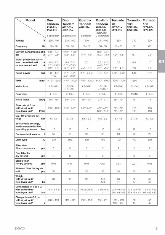
5. Technical Data
EN
2009/03� 9
Model DuoTandem4152-01a4152-51a
1�generator
DuoTandem4252-01a4252-51a
2�generators
QuattroTandem4642-51a
1�generator
QuattroTandem4682-51a4680-51b4682-52a2�generators
Tornado705172-01a5170-01b
Tornado1305272-01a5270-01b
Tornado1305272-02a5270-02b
Voltage V 230�/�400 230�/�400 400 230�/�400 230 230 220
Frequency Hz 50�-�60 50�-�60 50�-�60 50�-�60 50�-�60 50 60
Current consumption at 8 bar A
6�3C�-�7�0C
3�1C�-�2�5C
12�2C�-�14�3C
6�2C�-�5�0C 4�4C�-�4�8C
8�8C�-�9�6C
15,2C�-�16,6C 4�9C�-�4�3C 6,7 7,9
Motor protection switch max. permitted sett. A recommended sett. A
8�5�/�3�56�5C�-�7�6C�/�3�2C�-�2�5C
8�5�/�3�56�5C�-�7�6C�/�3�2C�-�2�5C
6,3
4�4C�-�5�0C
6,3�/�10,04�4C�-�5�0C
7,6�C�-�8,5�C
6,3
5�1C�-�4�3C
8,5
7,0
10
8,0
Rated power kW 1�3C�-�1�6C
1,402�7C�-�3�3C
2�8C�-�2�84C
2�2C�-�2�95C 4�4C�-�5�9C 0�92C�-�0�97C 1,42 1,70
RPM min-1 1410C-�1690C 1410C�-�1690C 1440C�-�1700C 1440C-�1700C 1420C-�1700C 1380 1710
Mains fuse LS-10Ad LS-20Ad
LS-10Ad
LS-10Ad LS-10Ad
LS-20A�dLS-10Ad LS-10Ad LS-10Ad
Fuse type IP�X4B IP�X4B IP�X4B IP�X4B IP�X4B IP�X4B IP�X4B
Noise levels dB(A) 68C�-�70C 69C�-�74C 70C�-�73C 74C�-�77C 68C�-�72C 70 74
Flow rate at 5 bar with dryair unita
w/o dryair unitb l/min105C�-�120C
-
210C�-�240C
-
215C-240C
-
430C-480C
470C�-�540C
62C�-�72C
70C�-�80C
125140
135150
On / Off pressure set-tings bar 6�/�7�8 6�/�7�8 6�5�/�8�5 6�5�/�8�5 6�/�7�8 6�/�7�8 6�/�7�8
Safety valve settings, maximum permissible operating pressure bar 10 10 10 10 10 10 10
Pressure tank volume l 50 50 90 90 20 20 20
Duty cycle % 100 100 100 100 100 100 100
Filter size: filter compressor µm 3 3 3 3 2 2 2
Fine filter for dry air unit µm 3 3 3 3 3 3 3
Sterile filterf
for dry air unit µm 0�01 0�01 0�01 0�01 0�01 0�01 0�01
Sintered filter for dry air unit µm 35 35 35 35 35 35 35
Weight with dryair unita
w/o dryair unitb kg64-
90-
98-
143134
3641
5247
5247
Dimensions (H x W x D) with dryair unita
w/o dryair unitb cm76�x�75�x�52
-76�x�79�x�52
-76�x102x�62
-76�x102x�62
-72�x�49�x�4666�x�49�x�43
72�x�49�x�4666�x�49�x�43
72�x�49�x�4666�x�49�x�43
Charge time 0-7.5 bar with dryair unita w/o dryair unitb s
198C�-�173C
-113C�-�99C
-180C�-�156C
-89C�-�77C
-126C�-�109C
100C�-�85C
6045
5840

EN
10� 2009/03
6. Functional layout6.1 Compressor with dry air unit
15
11
19
18
12
14
1
2
6.2 Compressor without a dry air unit
3
4
5a
2
67
16
8
9
11
12
14
15
1
17
13
13
10
1� Diaphragm�dryer2� Pressure�limiting�valve3� Rinsing�nozzles4� Dryer�hollow�fibres5� Fine�filter�/�Sterile�filter5a� Sintered�filter6� Condense�water�
collector7� Water�outlet�valve8/18� Nonreturn�valve9/19� Pressure�relief�valve10� Pressure�gauge11� Pressure�switch12� Pressure�tank13� Condensate�drainage�
valve14� Compressor�generator15� Intake�filter16� Cooling�element�with�
ventilation�fan17� Safety�valve
5

EN
2009/03� 11
7. Functional Description7.1 Compressor with dry air unitBrief functional description:
The�compressor�generator�(14)�draws�in�air�from�the�atmosphere�and�compresses�this�air�com-pletely�oil-free��It�then�transports�the�oil-free�and�compressed�air�to�the�drying�unit��The�cooling�element�(16)�and�the�diaphragm�dryer�(1)�extract�all�humidity�from�the�compreesed�air��The�oil-free,�clean�and�dry�air�is�then�made�available�to�the�operator�(e��g��turbine)�in�the�pressure�tank�(12)�
Detailed Functional Description:
• Compressor generatorAir�is�drawn�in�from�the�surrounding�atmosphere�through�the�intake�filter�(15)��The�plunger�of�the�compressor�generator�(14)�then�compresses�this�air��The�intake�and�outlet�valves�serve�to�block�the�flow�in�one�direction�at�a�time�so�that�the�compressed�air�is�fed�either�to�the�cooling�element�or�to�the�diaphragm�dryer�(1)�
• Cooling element and dry air unitThe�hot�and�moisture-containing�compressed�air�which�is�produced�by�the�compressor�generator�flows�to�the�cooling�element�(16)��Once�inside�the�cooling�element�the�compressed�air�is�cooled�to�a�temperature�just�above�room�temperature�and�the�water�condenses��100%�Saturated�compressed�air�and�condensated�water�exit�the�cooler�and�flow�to�the�water�separattor��The�cyclone�effect�and�coalescence�effect�at�the�sintered�filter�(5a)�cause�the�condensated�water�present�in�the�air�to�be�discharged�and�it�collects�in�the�water�collec-tor�vessel�(6)��The�automatic�wasser�outlet�valve�(7)�reacts�according�to�condensation�level�and�al-lows�the�collected�water�to�be�drained�off�cycli-cally�at�set�periods��Finally�the�air�is�fed�to�the�membrane�element��The�air�now�flows�through�the�membrane�fibres�(4),�whereby�the�water�mole-cules�present�in�the�air�are�diffused�through�the�membrane�wall�and�collect�on�the�outsides�of�the�hollow�fibres��Meanwhile�the�dried�air�flows�through�a�fine�filter�/�sterile�filter�(5),�pressure�valve�(2)�and�the�nonreturn�valve�(8)�to�the�pressure�tank�(12)�Regeneration�of�the�diaphragm�dryer�A�small�amount�of�dry�air�is�allowed�to�pass�over�the�purge�nozzles�(3)�to�the�outside�of�the�hol-low�fibre�particles��This�stream�of�air�serves�to�absorb�the�moisture�which�diffused�through�the�membrane�wall�and�transports�it�to�the�outside�environment��This�regeneration�process�is�
carried�out�continuously�during�operation��There�is�no�need�for�operation�during�a�period�of�idle�mode��The�pressure�relief�valve�(2)�incorporated�in�the�upper�part�of�the�membrane�element�en-sures�that�the�membrane�dryer�reaches�the�ra-ted�operating�pressure�in�the�shortest�possible�time�thereby�ensuring�optimum�drying�results�under�all�operating�conditions��A�humidity�indi-cator�has�been�integrated�into�this�upper�sec-tion�of�the�membrane�element�which�is�clearly�visible�through�the�transparent�upper�section��In�the�case�of�a�possible�malfunction�of�the�dryer�and�the�accompanying�insufficient�air�drying�the�colour�of�the�indicator�changes�from�blue�to�pink�
• Pressure switch fittingsWhen�a�user�(e��g��turbine)�is�extracting�com-pressed�air�the�pressure�within�the�compressed�air�tank�falls��If�the�minimum�possible�tank�pres-sure�allowed�is�registered�at�the�pressure�switch�(11)�then�the�compressor�generator�will�be�swit-ched�on��If�the�maximum�possible�tank�pressure�allowed�(circa�7�8�bar)�is�registered�at�the�pres-sure�switch�(11)�then�the�compressor�generator�will�be�switched�off��The�absolute�maximum�per-mitted�tank�pressure�of�10�bar�is�clearly�marked�on�the�pressure�gauge�(10)�in�red��The�safety�valve�(17)�prevents�the�maximum�permissible�tank�pressure�(10�bar)�from�being�exceeded��The�condensate�outlet�tap�(13)�can�be�used�in�order�to�drain�the�condensated�water�from�the�pressure�tank�by�opening�the�valve�
7.2 Compressor without a dry air unit
• compressor generatorThe�compressor�generator�(14)�draws�air�from�the�surrounding�environment�through�an�intake�filter�(15)�and�compresses�this�air�oil-free��The�inlet�and�outlet�valves�ensure�that�flow�in�only�one�direction�is�possible,�i�e��so�that�the�com-pressed�air�is�forced�through�the�non-return�val-ve�(18)�into�the�pressure�tank�(12)�
• pressure switchThe�compressor�generator�(14)�continuously�supplies�compressed�air�until�such�time�as�the�pressure�switch�(11)�setting�registers�the�maxi-mum�permitted�pressure�within�the�tank�(12)�and�then�the�compressor�generator�is�switched�off��After�switching�off�the�compressor�generator�the�pressure�hoses�are�vented�using�the�ex-haust�air�vent�(19)�

EN
12� 2009/03
• Pressure switch fittings see�previous�section,�"Detailed�Functional�Description�
EN
2009/03� 13
3
Installation
8. Transport and storage conditions
The�compressor�is�packed�in�a�special�transport�carton�for�shipping��This�serves�to�protect�the�appliance�from�damage�during�transport��Be�sure�to�set�the�compressor�in�an�upright�po-sition�during�transport�
Protect�the�compressor�during�transport�and�storage�from�humidity,�dirt�and�ex-tremes�of�temperature���Compressors�which�are�still�in�their�ori-ginal�packing�can�be�safely�stored�in�warm,�dry�and�dust-free�rooms�Danger of injury. The compressor may only be trans-ported when no pressure is present. Before transport the pressure tank and the pressure hoses must be vented thoroughly.
9. Set-up and initial use
Only fully qualified personnel are allowed to set up this appliance, to install it or to carry out commissi-oning. Before commissioning and first use all packing protection must be re-moved from the compressor unit.
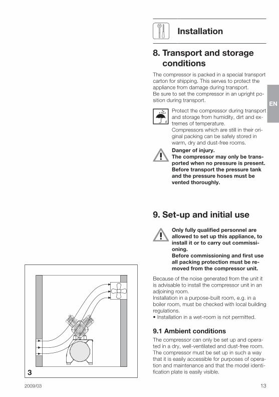
Because�of�the�noise�generated�from�the�unit�it�is�advisable�to�install�the�compressor�unit�in�an�adjoining�room�Installation�in�a�purpose-built�room,�e�g��in�a�boiler�room,�must�be�checked�with�local�building�regulations�•�Installation�in�a�wet-room�is�not�permitted��
9.1 Ambient conditionsThe�compressor�can�only�be�set�up�and�opera-ted�in�a�dry,�well-ventilated�and�dust-free�room�The�compressor�must�be�set�up�in�such�a�way�that�it�is�easily�accessible�for�purposes�of�opera-tion�and�maintenance�and�that�the�model�identi-fication�plate�is�easily�visible�
EN
14� 2009/03
4
20
22
21
The�compressor�must�be�set�up�on�a�flat�sur-face�(floor)�and�that�the�surface�is�sufficiently�stable��(Consider�the�compressor�weight�when�selecting�set�up�floor,��see�5��Technical�Data�)The�room�temperature�must�not�fall�below�+10�°C�and�must�not�be�allowed�to�+�exceed�+40�°C,�as�this�could�cause�interference�and�smooth�running�of�the�compressor�can�no�lon-ger�be�guaranteed���The�ideal�ambient�temperature�for�operation�lies�between�+10 °C�and�+25�°C�
Approximately�70%�of�the�electrical�en-ergy�consumed�by�the�compressors�is�converted�into�warmth�which�is�radiated�to�the�surroundings�Danger of overheating. The air suction side of the initial air filter and the ventilation slats of the generator, as well as the suction grille of the cooling element must be free of any obstruction and there must be sufficient distance to walls or other units (ca. 20 cm). We strongly recommend that additi-onal ventilation is made available in the room. Where room temperatures above +40 °C are experienced then supple-mentary ventilation for the room is necessary, see fig. 3.
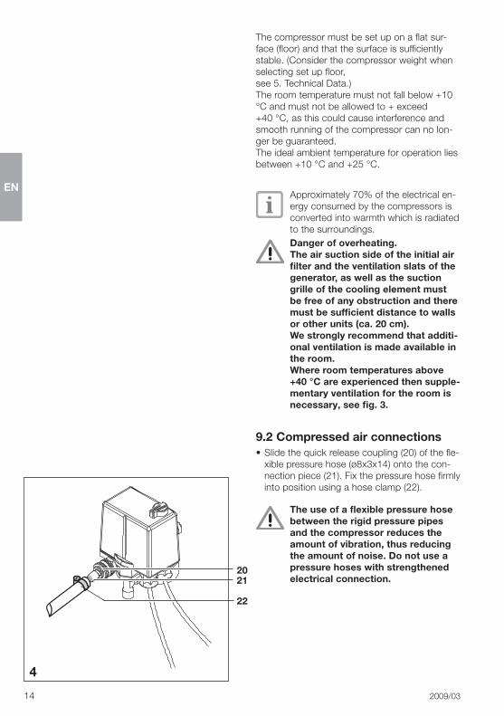
9.2 Compressed air connections•�Slide�the�quick�release�coupling�(20)�of�the�fle-
xible�pressure�hose�(ø8x3x14)�onto�the�con-nection�piece�(21)��Fix�the�pressure�hose�firmly�into�position�using�a�hose�clamp�(22)�
The use of a flexible pressure hose between the rigid pressure pipes and the compressor reduces the amount of vibration, thus reducing the amount of noise. Do not use a pressure hoses with strengthened electrical connection.
EN
2009/03� 15
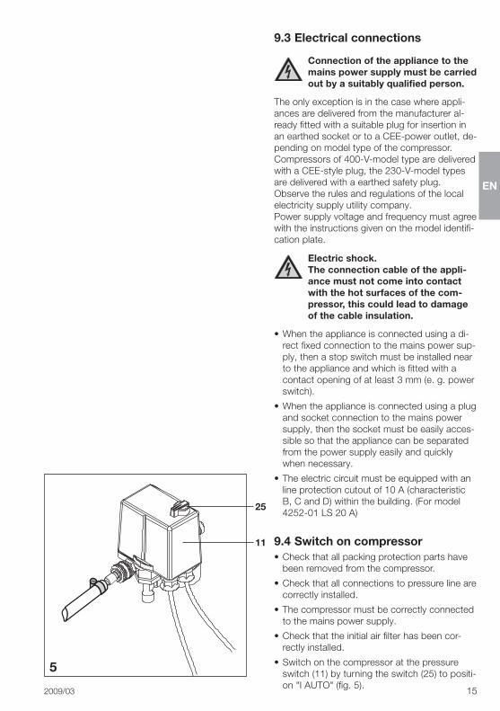
9.3 Electrical connections
Connection of the appliance to the mains power supply must be carried out by a suitably qualified person.
The�only�exception�is�in�the�case�where�appli-ances�are�delivered�from�the�manufacturer�al-ready�fitted�with�a�suitable�plug�for�insertion�in�an�earthed�socket�or�to�a�CEE-power�outlet,�de-pending�on�model�type�of�the�compressor�Compressors�of�400-V-model�type�are�delivered�with�a�CEE-style�plug,�the�230-V-model�types�are�delivered�with�a�earthed�safety�plug��Observe�the�rules�and�regulations�of�the�local�electricity�supply�utility�company��Power�supply�voltage�and�frequency�must�agree�with�the�instructions�given�on�the�model�identifi-cation�plate�
Electric shock. The connection cable of the appli-ance must not come into contact with the hot surfaces of the com-pressor, this could lead to damage of the cable insulation.
•�When�the�appliance�is�connected�using�a�di-rect�fixed�connection�to�the�mains�power�sup-ply,�then�a�stop�switch�must�be�installed�near�to�the�appliance�and�which�is�fitted�with�a�contact�opening�of�at�least�3�mm�(e��g��power�switch)�
•�When�the�appliance�is�connected�using�a�plug�and�socket�connection�to�the�mains�power�supply,�then�the�socket�must�be�easily�acces-sible�so�that�the�appliance�can�be�separated�from�the�power�supply�easily�and�quickly�when�necessary�
•�The�electric�circuit�must�be�equipped�with�an�line�protection�cutout�of�10�A�(characteristic�B,�C�and�D)�within�the�building��(For�model�4252-01�LS�20�A)
9.4 Switch on compressor•�Check�that�all�packing�protection�parts�have�
been�removed�from�the�compressor�
•�Check�that�all�connections�to�pressure�line�are�correctly�installed�
•�The�compressor�must�be�correctly�connected�to�the�mains�power�supply�
•�Check�that�the�initial�air�filter�has�been�cor-rectly�installed�
•�Switch�on�the�compressor�at�the�pressure�switch�(11)�by�turning�the�switch�(25)�to�positi-on�"I�AUTO"�(fig��5)��
5
11
25

EN
16� 2009/03
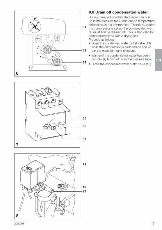
9.5 Motor protection switch settings
The�motor�protection�switch�is�the�same�for�all�models�except�Duo�and�Quattro�Tandem�and�is�constructed�together�with�the�pressure�switch�(fig��6)��This�can�be�adjusted�at�setting�screw�(31)�The�two�models�Duo�and�Quattro�Tandem�are�designed�whereby�the�motor�protection�switch�is�situated�on�the�control�unit�of�the�compressor��On�the�control�box�is�a�setting�screw�(35)�as�well�as�a�start�and�a�stop�button�(36�and�37),��see�fig��7�Every�motor�protection�switch�is�set�before�lea-ving�the�factory��The�factory�settings�are�accor-ding�to�the�values�found�under�section�4��"Technical�Data"�recommended�values�for�50�Hz�electrical�frequency��The�setting�should�be�che-cked�when�the�appliance�is�set�up�and��should�only�be�altered�if�specially�required�
Overheating. The maximum values set out in sec-tion 4. "Technical Data" must not be exceeded!
Checking�and�resetting�of�the�motor�protection�switch�should�be�carried�out�as�described�below:•�Remove�the�protective�cover�(11)�over�the�
pressure�switch�or�of�the�control�unit�(for�mo-dels�Duo�and�Quattro-Tandem)�
•�Measure�the�maximum�current�(the�value�im-mediately�before�the�switch�off�pressure�is�activated)�
Electric shock. Any measurements or settings can only be carried out when no power is present in the compressor unit.
•�Set�the�motor�protection�switch�using�the�ad-justment�screws�(31�or�35,�depending�on�mo-del)�to�the�measured�value,�see�figs��6�and�7�
9.6 Check safety valve settingsThe�safety�valve�has�been�factory�set�at�10�bar,�checked�and�approved�(with�stamp)�
Danger of excess pressure The safety valve setting must not be altered.
The�safety�valve�function�must�be�checked�when�commissioning�the�appliance�and�using�for�the�first�time�
•�Switch�on�the�compressor�unit�and�charge�the�pressure�tank�until�it�reaches�the�shut-off�level�
•�Rotate�the�screw�setting�(17)�of�the�safety�val-ve�a�few�turns�to�the�left,�until�the�valve�blows�off,�see�fig��8�
•� �Only�allow�the�Safety�valve�to�blow�off�air�for�a�short�period��Rotate�the�setting�screw�(17)�to�the�right�until�it�is�firm��The�valve�must�now�be�in�its�closed�position�
Damage to the safety valve. The safety valve must never be used for venting the pressure tank.
9.7 Check pressure switch and re-set where deviant
The�pressure�switch�is�factory�set�At�ca��6�bar�tank�pressure�the�generator�swit-ches�on�automatically��At�7�8�bar�it�switches�itsel�off�
If�required,�the�operating�pressure�of�the�compressor�can�be�altered�at�the�pres-sure�switch���To�do�this,�first�the�cut�out�pressure�and�then�the�cut�in�pressure�must�be�chan-ged�using�the�pressure�difference�(Dp)�Electric shock. When carrying out this operation the protective cover of the pressure switch (11) must first be removed. Adjustment of the settings can only be carried out when the compressor is supplied with current.
Set�the�shut-off�pressure�p�using�the�setting�screw�(32)�(fig��7):�direction�of�arrow�"+"�higher�and�in�direction�of�arrow�"–"�lower��The�pressure�difference�will�also�be�altered�when�carrying�out�this�step�(if�necessary�readjust)��The�shut-off�pressure�must�be�at�least�0�5�bar�below�the�sa-fety�valve�setting�of�maximum�pressure�(10�bar),�otherwise�the�safety�valve�will�open��The�com-pressor�generator�will�not�reach�the�cut�out�pressure�and�will�run�continuously�The�pressure�difference�p�between�cut�in�pres-sure�and�cut�out�pressure�can�be�adjusted�using�the�setting�screw�(33)�by�turning�in�the�direction�of�the�Plus�or�Minus�sign��The�pressure�tank�must�be�under�pressure�during�this�setting�
EN
2009/03� 17
6
7
9.8 Drain off condensated waterDuring�transport�condensated�water�can�build�up�in�the�pressure�tank�kann�due�to�temperature�differences�in�the�environment��Therefore,�before�the�compressor�is�set�up�the�condensated�wa-ter�must�first�be�drained�off��This�is�also�valid�for�compressors�fitted�with�a�drying�unitProceed�as�follows:•�Open�the�condensed�water�outlet�valve�(13)�
while�the�compressor�is�switched�on�and�un-der�the�maximum�tank�pressure�
•�Wait�until�the�condensated�water�has�been�completely�blown�off�from�the�pressure�tank�
•�Close�the�condensed�water�outlet�valve�(13)�
8
1317
35
36
37
31
32
33
11
EN
18� 2009/03
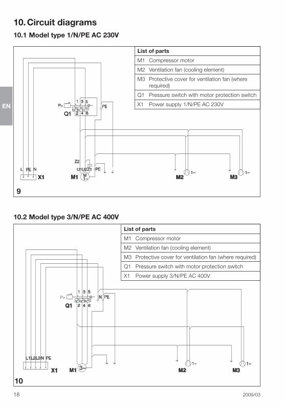
10.2 Model type 3/N/PE AC 400V
10. Circuit diagrams10.1 Model type 1/N/PE AC 230V
9
10
List of parts
M1� Compressor�motor
M2� Ventilation�fan�(cooling�element)
M3� Protective�cover�for�ventilation�fan�(where�required)
Q1� Pressure�switch�with�motor�protection�switch
X1� Power�supply�1/N/PE�AC�230V
List of parts
M1� Compressor�motor
M2� Ventilation�fan�(cooling�element)
M3� Protective�cover�for�ventilation�fan�(where�required)
Q1� Pressure�switch�with�motor�protection�switch
X1� Power�supply�3/N/PE�AC�400V

EN
2009/03� 19
10.3 Model type 3/N/PE AC 400V, 2 aggregates, Duo Tandem
10.4 Model type 3/N/PE AC 400V, 2 aggregates, Quattro Tandem
11
12
List of parts M5�Ventilation�fan�for�noise�reducing�co-ver�(if�required)
A1� Controller M3� Ventilation�fan�(cooling) Q2,Q3� Motor�protection�switch
K1� Time-lag�relay M4� Ventilation�fan�(cooling) X1� Power�supply�3/N/PE�AC�400V
M1,M2� Compressor�motor Q1� Pressure�switch X2,X3� Terminal�clamp�at�A1

EN
20� 2009/03
10.5 Model type 3/N/PE AC 230V, 2 aggregates, Quattro Tandem
13
EN
2009/03� 21
14
25
10
11
Use
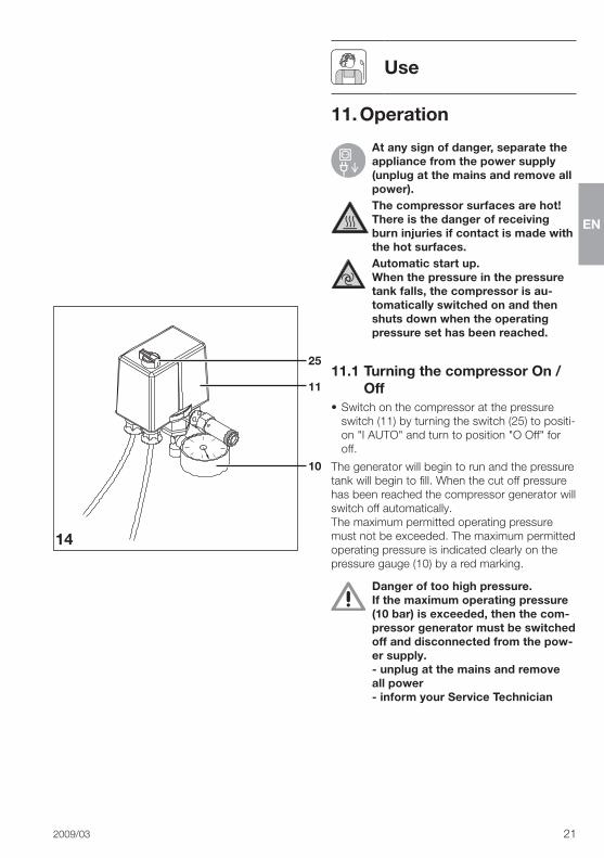
11. Operation
At any sign of danger, separate the appliance from the power supply (unplug at the mains and remove all power).The compressor surfaces are hot! There is the danger of receiving burn injuries if contact is made with the hot surfaces.Automatic start up. When the pressure in the pressure tank falls, the compressor is au-tomatically switched on and then shuts down when the operating pressure set has been reached.
11.1 Turning the compressor On / Off
•�Switch�on�the�compressor�at�the�pressure�switch�(11)�by�turning�the�switch�(25)�to�positi-on�"I�AUTO"�and�turn�to�position�"O�Off"�for�off�
The�generator�will�begin�to�run�and�the�pressure�tank�will�begin�to�fill��When�the�cut�off�pressure�has�been�reached�the�compressor�generator�will�switch�off�automatically�The�maximum�permitted�operating�pressure�must�not�be�exceeded��The�maximum�permitted�operating�pressure�is�indicated�clearly�on�the�pressure�gauge�(10)�by�a�red�marking�
Danger of too high pressure. If the maximum operating pressure (10 bar) is exceeded, then the com-pressor generator must be switched off and disconnected from the pow-er supply. - unplug at the mains and remove all power - inform your Service Technician
EN
22� 2009/03
12. Maintenance intervals – Operator / Service Technician
Maintenance tasks Section Period
Drain�off�condensated�water–� Compressor�without�drying�unit–�where�relative�humidity�is�higher–� Compressor�with�drying�unit
13�3monthlydailycheck�two�times�a�year,�drain�off�if�necessary
Check�safety�valve�settings 13�4 two�times�a�year
Changing�the�filter 13�5 once�a�year
Change�vibration�dampers 13�6 alle�4�Jahreevery�four�years
13. Maintenance
Repairs and maintenance above and beyond that included in general maintenance procedures may only be carried by qualified personnel or our service team. Only spare parts or special acces-sories specifically approved by the manufacturer should be used.Before carrying out any mainte-nance and repair work on the com-pressor it must be switched off and separated from the power supply (unplug at the mains and remove all power).
In�order�to�ensure�that�the�compressor�is�func-tioning�smoothly�the�maintenance�steps�descri-bed�under�sections�13�1�to�13�6�should�be�car-ried�out�at�regular�intervals�
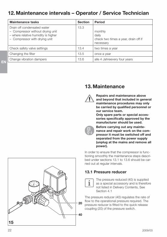
13.1 Pressure reducer
The�pressure�reduced�(40)�is�supplied�as�a�special�accessoriy�and�is�therefore�not�listed�in�Delivery�Contents,�See�Section�4�1
The�pressure�reducer�(40)�regulates�the�rate�of�flow�to�the�operational�pressure�required��The�pressure�reducer�is�fitted�to�the�quick�release�coupling�(20)�of�the�pressure�switch�
40
15
20

EN
2009/03� 23
13
16
17
18
40
41
42
13.2 Setting the pressure reducerIn�order�to�set�the�rate�of�flow�first�operate�part�of�the�equipment�(syringe,�turbine�etc�)��Lift�the�rotary�knob�(41)�of�the�pressure�reducer�(40)�and�turn�in�the�direction�of�the�arrow�to�„+”�(raise�flow�pressure�)�or�in�direction�„–”�(lower�pressure�flow)�until�the�required�pressure�is�shown�on�the�pressure�gauge�(42)Finally�press�the�rotating�knob�downwards�again�until�it�en-gages�and�is�secure�against�accidental�reset-ting��The�adjusted�pressure�is�now�fixed��For�fur-ther�notes�on�rate�of�flow�and�pressure�settings�see�the�manufacturer's�instructions�for�the�nec-essary�equipment�(e�g��turbine)�
13.3 Drain off condensated waterThe�condensated�water�is�automatically�ex-tracted�for�those�compressor�types�fitted�with�a�dry�air�unit���For�compressors�without�the�dry�air�unit�the�condensated�water�must�be�drained�off�at�least�1x�month!In�countries�with�a�high�relative�humidity�the�condensated�water�must�be�blown�off�daily!Procedure:•�With�compressor�switched�on�and�under�ma-
ximum�tank�prressure�slowly�open�the�con-densated�water�drain�tap�(13)�
Careful - danger of condensated watersplashing, if necessary apply a hose
•�Wait,�until�the�condensated�water�has�com-pletely�drained�from�the�tank�
•�Close�the�drainage�tap�(13)�
13.4 Check safety valve settings17The�safety�valve�(17)�has�been�factory�set�at�10�bar,�checked�and�approved�(with�stamp)�
damage to safety valve Do not adjust the safety valve set-ting and do not use to vent the pres-sure tank.
•�Switch�on�the�compressor�unit�and�charge�the�pressure�tank�until�it�reaches�the�shut-off�level�
•�Rotate�the�screw�(17)�one�or�two�turns�to�the�left,�until�the�safety�valve�begins�to�blow�off�air��Only�allow�the�Safety�valve�to�blow�off�air�for�a�short�period��Turn�the�screw�(17)�to�the�right�until�it�fully�engages,�the�valve�must�now�be�in�the�closed�position�
17

EN
24� 2009/03
19
20
21
15a
15
5a
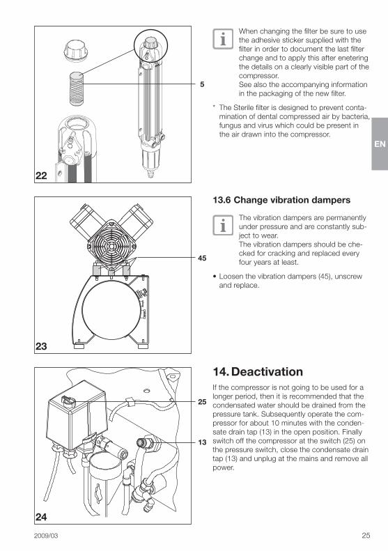
13.5 Changing the filter
Always replace used filters. Never clean and reuse a filter. Cleaning damages the filter.The�replacement�interval�of�the�filter�in-serts�depends�to�a�large�extent�on�the�amount�of�dust�in�the�surrounding�air��Regular�changing�of�the�filter�guaran-tees�a�continuous�high�quality�of�the�compressed�air�and�increases�the�life�of�the�compressor��We�strongly�recommend�that�the�filter�of�the�compressor�unit,�under�correct�set�up�under�normal�conditions�(see�Section�9�1�"Environmental�Conditions")�be�chanfed�once�each�year��Where�a�dry�air�unit�is�present,�this�is�valid�for�filter�fitted�in�this�unit�as�well�
Filter order numbers:
Compressor�models�5170,�5172,�5270,�5272Intake�filter�(15a)���������������������������� 5430-982-00
Compressor�models�4152,�4252,�4642,�4682,�5150,�5152,�5250,�5252,�5352,�5452Intake�filter�(15)������������������������������ 0832-982-00
Compressor�models�with�dry�air�unit�4152,�4252,�4642,�4682,�5152,�5172,�5252,�5272,�5352,�5452Sintered�filter�(5a) �������������������������� 1650-101-00Fine�filter�(5)�fig��21������������������������ 1610-121-00orSterile�filter*�(5)�fig��21�������������������� 1640-981-00
EN
2009/03� 25
22
23
24
5
45
25
13
When�changing�the�filter�be�sure�to�use�the�adhesive�sticker�supplied�with�the�filter�in�order�to�document�the�last�filter�change�and�to�apply�this�after�enetering�the�details�on�a�clearly�visible�part�of�the�compressor��See�also�the�accompanying�information�in�the�packaging�of�the�new�filter�
*� The�Sterile�filter�is�designed�to�prevent�conta-mination�of�dental�compressed�air�by�bacteria,�fungus�and�virus�which�could�be�present�in�the�air�drawn�into�the�compressor�
13.6 Change vibration dampers
The�vibration�dampers�are�permanently�under�pressure�and�are�constantly�sub-ject�to�wear��The�vibration�dampers�should�be�che-cked�for�cracking�and�replaced�every�four�years�at�least�
•�Loosen�the�vibration�dampers�(45),�unscrew�and�replace�
14. DeactivationIf�the�compressor�is�not�going�to�be�used�for�a�longer�period,�then�it�is�recommended�that�the�condensated�water�should�be�drained�from�the�pressure�tank��Subsequently�operate�the�com-pressor�for�about�10�minutes�with�the�conden-sate�drain�tap�(13)�in�the�open�position��Finally�switch�off�the�compressor�at�the�switch�(25)�on�the�pressure�switch,�close�the�condensate�drain�tap�(13)�and�unplug�at�the�mains�and�remove�all�power�

EN
26� 2009/03
Troubleshooting
15. Tips for Operators and TechniciansAny repairs above and beyond routine maintenance must be carried out by suitably qualified personnel or one of our service technicians.
Before troubleshooting remove the unit from the mains supply.
Problem Probable cause Solution1. Compressor does not start. •�No�supply�voltage •�Check�the�mains�fusing,��
if�necessary�reset�the�switch�(if�the�cut-out�fuse�is�defect,�replace)�
•�Pressure�switch�not�swit-ched�on�
•�Switch�pressure�switch�on�•� Inform�the�Service�Technician
2. Compressor does not turn off
•�Compressor�is�too�small,�air�consumption�too�high
•�Calculate�the�amount�of�air�re-quired�(this�cab�ne�up�to�50�l/min�per�treatment�station),�if�necessa-ry�install�a�larger�compressor�
•�Leak�in�compressed�air�system
•�Find�leak�and�seal•� Inform�the�Service�Technician
3. Compressor switches on from time to time although no air has been used by operator.
•�Leak�in�compressed�air�system
•�Find�leak�and�seal•� Inform�the�Service�Technician
4. Loud knocking noises from compressor.
•�Bearing�damage •� Inform�the�Service�Technician
5. Fall in performance. Compressor needs longer to fill the pressure tank. For charge times see section 5. "Technical Data".
•� Intake�filter�dirty •�Replace�the�intake�filter�at�least�1x�year��The�intake�filter�must�not�be�cleaned�and�reinserted�
•�Dry�air�unit�is�faulty •�Replace�dry�air�unit•� Inform�the�Service�Technician
6. Water leaks from tool (e. g. turbine)
•�Condensated�water�in�pressure�tank��Dry�air�unit�is�faulty
•� Inform�the�Service�Technician
•�compressor�without�drying�unit
•�At�least�1x�month�the�condensa-ted�water�from�the�tank�should�be�drained�off��In�areas�of�higher�than�average�relative�humidity�and�in�tropical�countries�the�condensa-ted�water�from�the�tank�should�be�drained�off�daily��Checki�and�ob-serve�the�ambient�temperature�of�the�compressor�(see�sectiopn�9�1�"Environmental�conditions")�

EN
2009/03� 27
16. Tips for TechniciansThe following descriptions concerning Trouble-shooting are designed solely for Service Technicians. Repairs may only be carried out by fully qualified Service Technicians.
Problem Probable cause Solution1. Compressor does
not start.•�Pressure�switch�not��
switched�on�•�Switch�pressure�switch�on��
If�the�pressure�switch�stays�switched�on�for�a�short�period�of�time�and�then�the�motor�cuts�out,�then�the�current�should�be�checked�carefully;�rotary�A�C�current�in�all�three�phases�and�A�C�power�in�a�single�phase�
•�Check�the�mains�fusing,�if�necessary�switch�on�appliance�again��If�the�cut-out�fuse�is�defective,�replace��Check�the�power�supply�voltage��Check�all�phases�for�3-phase�motors�
•�No�supply�voltage��3-Phase�motors:�one�phase�is�missing�or�does�not�start�up�(ge-nerates�loud�noises)
•�Check�the�mains�fusing,�if�necessary�switch�on�appliance�again��If�the�cut-out�fuse�is�defective,�replace��Check�the�power�supply�voltage��Check�all�phases�for�3-phase�mo-tors�generator
•� �Undervoltage� •�Measure�the�supply�voltage,�if�neces-sary�call�an�electrician�
•�Motor�protection�switch�setting�is�too�low�(see�section�5,�Technical�Data)�
•�Measure�current��Set�the�motor�pro-tection�switch�to�the�measured�va-lues��For�a�detailed�description�see�section�9�5�"Motor�protection�switch�settings"�
•�Motor�protection�switch�defective�
•�Check�motor�protection�switch;�if�de-fective,�replace�
•�Exhaust�air�vent�defective,�gene-rator�is�working�against�pressure�
•�Check�whether�the�exhaust�air�vent�(9/19)�blows�off�air�after�the�genera-tor�has�switched�off��Ensure�exhaust�air�vent�is�free�to�move�or�replace�
•�Running�of�generator�indicates�mechanical�restistance�(piston�blocked);�motor�protection�switch�activated�
•�Unplug�at�the�mains�and�remove�all�power,�remove�the�cover�of�the�crankcase�housing�to�the�blocked�compressor�and�rotate�the��fan�wheel;�if�this�is�not�possible,�replace�either�the�piston�and�cylinder�or�the�complete�generator�
� Duo�and�Quattro�Tandem�com-pressors�can�be�operated�on�only�one�generator�for�a�brief�period��


DÜRR DENTAL AGHöpfigheimer Strasse 17 74321 Bietigheim-BissingenGermanyFon: +49 7142 [email protected]