Embed Size (px)
Citation preview
Dynamic local sound field synthesiswith multi-channel 1-bit signal reproduction system
Kakeru KUROKAWA(1), Izumi TSUNOKUNI(2), Yusuke IKEDA(3),Yasuhiro OIKAWA(4)
(1)Tokyo Denki University, Japan, [email protected](2)Tokyo Denki University, Japan, [email protected]
(3)Tokyo Denki University, Japan, [email protected](4)Waseda University, Japan, [email protected]
AbstractTo reproduce sound field accurately, local sound field synthesis(Local SFS) with virtual loudspeakers that areplaced densely around a local listening area have been proposed. In local SFS, it is necessary to limit the sizeof the listening area. Thus, a listener’s head can move out of a listening area due to the natural movement of thelistener. In this paper, we propose the concept of a dynamic sound field synthesis system which can moves thesound field synthesis area so as to track the listener’s head to allow the listener’s movement. For the purposeof facilitating the construction of the massive loudspeaker system in an ordinary room, we utilize a playbacksystem based on a high-speed 1-bit signal that can directly drive a loudspeaker. The proposed system canmove the listening area by switching the corresponding local SFS signals obtained from the database includingthe source signals convolved with the driving functions to reproduce the multiple local area. In simulationexperiments, reproduction errors of dynamic local and ordinary SFSs for a plane wave are compared to evaluatethe accuracy of sound field by dynamic local SFS.Keywords: Sound Field Reproduction, delta-sigma modulation, Digital Loudspeaker Array, CPU/FPGASoC
1 INTRODUCTIONRecently, many techniques for physical sound field synthesis (SFS) have been studied such as wave field syn-thesis (WFS)[1, 2], higher-order ambisonics (HOA)[3, 4], boundary surface control (BoSC)[5], etc. In physicalSFS, broadly arranging and controlling a large number of loudspeakers in a room is necessary. Thus, as thenumber of loudspeakers increases, the implementation cost rises. In our previous studies[6, 7, 8], the scale ofreproduction system is small enough to construct a physical sound field reproduction system in a small roomof an ordinary home, by utilizing a digital loudspeaker array which removes A/D converters and amplifiers.To improve synthesis accuracy at frequencies higher than the spatial Nyquist frequency corresponding to theloudspeaker density, local SFS techniques have been studied[9]. To enable the listener to move freely in localSFS, the local reproduction area must track the movement/location listener’s head.In this paper, we introduce the concept of dynamic local SFS system using digital loudspeaker with multi-channel 1-bit signal. In addition, the reproduction errors of dynamic local SFS and ordinary SFS for a planewave are compared to evaluate reproduction accuracy of dynamic local SFS by simulation experiments.
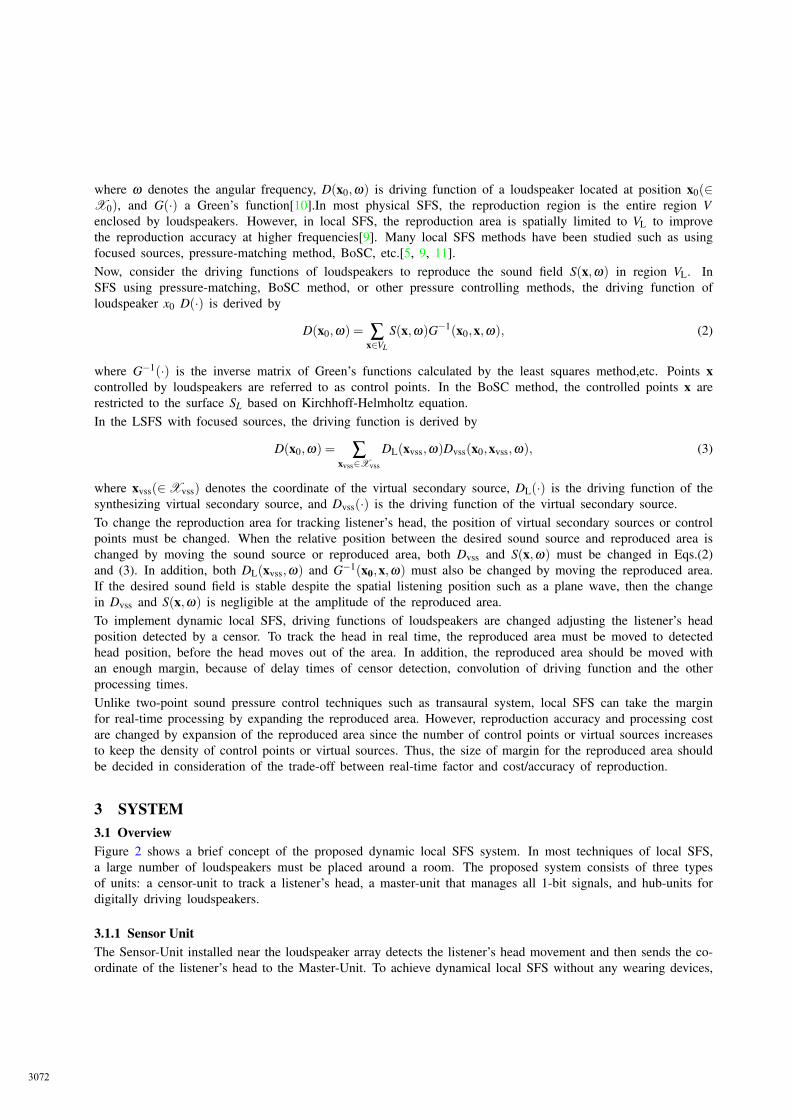
2 DYNAMIC LOCAL SOUND FIELD SYNTHESISFigure.1 shows the concept of dynamic local SFS. In general[10], the reproduced sound field P(x,ω) inside theregion V enclosed by loudspeakers is represented as,
P(x,ω) = ∑x0∈X0
D(x0,ω)G(x0,x,ω) (x ∈V ), (1)
3071
where ω denotes the angular frequency, D(x0,ω) is driving function of a loudspeaker located at position x0(∈X0), and G(·) a Green’s function[10].In most physical SFS, the reproduction region is the entire region Venclosed by loudspeakers. However, in local SFS, the reproduction area is spatially limited to VL to improvethe reproduction accuracy at higher frequencies[9]. Many local SFS methods have been studied such as usingfocused sources, pressure-matching method, BoSC, etc.[5, 9, 11].Now, consider the driving functions of loudspeakers to reproduce the sound field S(x,ω) in region VL. InSFS using pressure-matching, BoSC method, or other pressure controlling methods, the driving function ofloudspeaker x0 D(·) is derived by
D(x0,ω) = ∑x∈VL
S(x,ω)G−1(x0,x,ω), (2)
where G−1(·) is the inverse matrix of Green’s functions calculated by the least squares method,etc. Points xcontrolled by loudspeakers are referred to as control points. In the BoSC method, the controlled points x arerestricted to the surface SL based on Kirchhoff-Helmholtz equation.In the LSFS with focused sources, the driving function is derived by
D(x0,ω) = ∑xvss∈Xvss
DL(xvss,ω)Dvss(x0,xvss,ω), (3)
where xvss(∈Xvss) denotes the coordinate of the virtual secondary source, DL(·) is the driving function of thesynthesizing virtual secondary source, and Dvss(·) is the driving function of the virtual secondary source.To change the reproduction area for tracking listener’s head, the position of virtual secondary sources or controlpoints must be changed. When the relative position between the desired sound source and reproduced area ischanged by moving the sound source or reproduced area, both Dvss and S(x,ω) must be changed in Eqs.(2)and (3). In addition, both DL(xvss,ω) and G−1(x0,x,ω) must also be changed by moving the reproduced area.If the desired sound field is stable despite the spatial listening position such as a plane wave, then the changein Dvss and S(x,ω) is negligible at the amplitude of the reproduced area.To implement dynamic local SFS, driving functions of loudspeakers are changed adjusting the listener’s headposition detected by a censor. To track the head in real time, the reproduced area must be moved to detectedhead position, before the head moves out of the area. In addition, the reproduced area should be moved withan enough margin, because of delay times of censor detection, convolution of driving function and the otherprocessing times.Unlike two-point sound pressure control techniques such as transaural system, local SFS can take the marginfor real-time processing by expanding the reproduced area. However, reproduction accuracy and processing costare changed by expansion of the reproduced area since the number of control points or virtual sources increasesto keep the density of control points or virtual sources. Thus, the size of margin for the reproduced area shouldbe decided in consideration of the trade-off between real-time factor and cost/accuracy of reproduction.
3 SYSTEM3.1 OverviewFigure 2 shows a brief concept of the proposed dynamic local SFS system. In most techniques of local SFS,a large number of loudspeakers must be placed around a room. The proposed system consists of three typesof units: a censor-unit to track a listener’s head, a master-unit that manages all 1-bit signals, and hub-units fordigitally driving loudspeakers.
3.1.1 Sensor UnitThe Sensor-Unit installed near the loudspeaker array detects the listener’s head movement and then sends the co-ordinate of the listener’s head to the Master-Unit. To achieve dynamical local SFS without any wearing devices,
3072
Figure 1. Concept of dynamic local sound field reproduction. x0 denotes the coordinate of the loudspeakersplaced on the closed surface S; blue and red points are the coordinates of the virtual secondary source placedon the closed surface SL and SL
′; and S(·) is the sound field of the desired virtual source, SL and S′L.
Hub Unit
FPGA Non Inver!ng
CMOS Buffer
Inver!ng
CMOS Buffer
Non Inver!ng
CMOS Buffer
Inver!ng
CMOS Buffer
・・・・
Buffer
+
-
+
-
Master Unit
StorageDevice
Main SoC
FPGA
User
Interfaces
Depth Sensor
Master Clock Signal
Linux OS
Central Control App. CPU
Buffer 32-ch 1-bit Signal
Clock Generator
Frame Clock Signal
Depth Senso
ListenerLoad
ing Al
l-ch
bit
Digital Loudspeaker Array
Sending Listener’s Head Position Sensor Unit
Figure 2. Brief concept of dynamic local SFS system.
3073
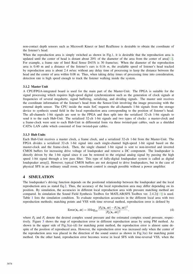
non-contact depth sensors such as Microsoft Kinect or Intel RealSense is desirable to obtain the coordinate ofthe listener’s head.When the reproduction area is simply switched as shown in Fig.1, it is desirable that the reproduction area isupdated until the center of head is distant about 20% of the diameter of the area from the center of area[12].For example, a frame rate of Intel Real Sense D435i is 30 frame/sec. When the diameter of the reproductionarea is 0.40 m and a distance of the listener’s ears is 0.16 m, the available speed of listener’s head trackedby reproduction area is about 2.4 m/sec without any delay time of processing to keep the distance between thehead and the center of area within 0.08 m. Thus, when taking delay times of processing time into consideration,detection rate is high speed enough to track the listener walking inside the system.
3.1.2 Master UnitA CPU/FPGA-integrated board is used for the main part of the Master-Unit. The FPGA is suitable for thesignal processing which requires high-speed digital synchronization such as the generation of clock signals atfrequencies of several megahertz, signal buffering, serializing, and dividing signals. The master unit receivesthe coordinate information of the listener’s head from the Sensor-Unit involving the image processing with theexternal depth sensor. The CPU inside the main SoC requests the all-channels 1-bit signals from the storagedevice to synthesis sound field in the local reproduction area corresponding to the position of listener’s head.The all-channels 1-bit signals are sent to the FPGA and then split into the serialized 32-ch 1-bit signals tosend it to the each Hub-Unit. The serialized 32-ch 1-bit signals and two types of clocks: a master-clock anda frame-clock were sent to each Hub-Unit in differential form via three twisted-pair cables, such as a shieldedCAT5e LAN cable which consisted of four twisted-pair cables.
3.1.3 Hub UnitsEach Hub-Unit receives a master clock, a frame clock, and a serialized 32-ch 1-bit from the Master-Unit. TheFPGA divides a serialized 32-ch 1-bit signal into each single-channel high-speed 1-bit signal based on themaster-clock and the frame-clock. Then, the single channel 1-bit signal is sent to non-inverted and invertedCMOS buffers for increasing drive voltage of loudspeaker and remove a DC component. The loudspeaker isdirectly driven by the 1-bit signal since it can be restored to the original analog signal by passing the highspeed 1-bit signal through a low pass filter. This type of fully-digital loudspeaker system is called as digitalloudspeaker array[]. However, typical CMOS buffers are not designed to drive loudspeakers, but in the case ofphysical SFS in an ordinary small room, wavefront control is enough possible without a power amplifier.
4 SIMULATIONThe loudspeaker’s driving function depends on the positional relationship between the loudspeaker and the localreproduction area as stated Eq.2. Thus, the accuracy of the local reproduction area may differ depending on itsposition. By simulation, the accuracies in different local reproduction area with pressure matching method arecompared. In simulation the Sound Field Synthesis Toolbox for MATLAB(SFS Toolbox ver. 2.4.2)[13] is used.Table 1 lists the simulation condition. To evaluate reproduction accuracies in the different local area with tworeproduction methods; matching points and VSS with time reversal method, reproduction error is defined by
Error(xi,ω) = 10log10|Pd(xi,ω)−Ps(xi,ω)|2
|Pd(xi,ω)|2, (4)
where Pd and Ps denote the desired complex sound pressure and the estimated complex sound pressure, respec-tively. Figure 3 shows the map of reproduction error in different reproduction areas by using PM method. Asshown in the upper side of Fig.3(a)–(d) for matching point method, the reproduction error is almost same de-spite of the position of reproduced area. However, the reproduction error was increased only when the center ofthe reproduction area was placed in the direction of the sound source as shown in Fig.3(e) for matching pointmethod. On the other hand, reproduction error becomes worse in local SFS with time-reversal VSS, when the
3074
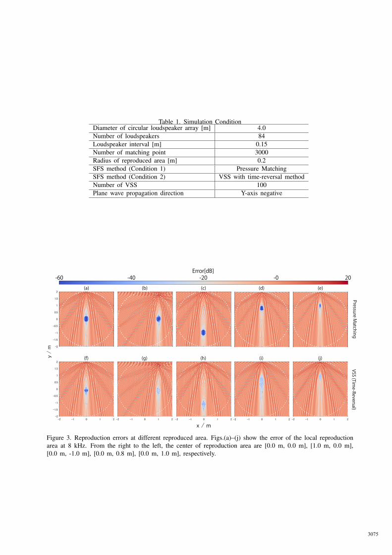
Table 1. Simulation ConditionDiameter of circular loudspeaker array [m] 4.0Number of loudspeakers 84Loudspeaker interval [m] 0.15Number of matching point 3000Radius of reproduced area [m] 0.2SFS method (Condition 1) Pressure MatchingSFS method (Condition 2) VSS with time-reversal methodNumber of VSS 100Plane wave propagation direction Y-axis negative
-60 -40 -20 -0 20(a) (b) (c)
Error[dB]
(d) (e)
(f) (g) (h) (i) (j)
Figure 3. Reproduction errors at different reproduced area. Figs.(a)–(j) show the error of the local reproductionarea at 8 kHz. From the right to the left, the center of reproduction area are [0.0 m, 0.0 m], [1.0 m, 0.0 m],[0.0 m, -1.0 m], [0.0 m, 0.8 m], [0.0 m, 1.0 m], respectively.
3075
reproduction area is deviated from the center.
5 CONCLUSIONIn this paper, we proposed the concept of dynamic local SFS system using a digital loudspeaker array andevaluate the accuracy of the dynamic local SFS by 2D simulation. The simulation results show that localSFS using PM method maintains higher accuracy at higher frequency by moving the position of the localreproduction area. In the future works, we will physically evaluate dynamic local SFS by using the proposedsystem.
ACKNOWLEDGEMENTSThis work was supported by JSPS KAKENHI Grant Number 17KT0142.
REFERENCES[1] A.J. Berkhout, D.D. Viries and P. Vogel, “Acoustic control by wave field synthesis”, J. Acoust. Soc. Am.
Vol.93, No.5, pp. 2764–2778, 1993.
[2] S. Spors, R. Rabenstein and J. Ahrens, “The Theory of Wave Field Synthesis Revisited”, 124th AES Conv.,2008.
[3] P. Fellget, “Ambisonics. Part one: General system description”, Studio Sound, Vol.17 pp. 20–22, 1975
[4] D.G. Malham and A. Myatt, “3D Sound Spatialization using Ambisonic Techniques”, Computer Music Jour-nal, Vol.9, No, 4, pp. 503–516, 1995.
[5] Shiro Ise, “A Principle of Sound Field Control Based on the Kirchhoff-Helmholtz Integral Equation and theTheory of Inverse Systems,” Acta Acustica united with Acustica, Vol.85, No.1, pp. 78–87, 1999.
[6] Kurokawa et. al., “Three-Dimensional Large-Scale Loudspeaker Array System Using High-Speed 1-Bit Sig-nal for Immersive Sound Field Reproduction,” AES International Conf. on Spatial Reproduction, Jul. 2018.
[7] Yamanaka et. al., “Large-scale loudspeaker array system for sound field reproduction using high-speed 1bitsignal processing,” 5th ASA and ASJ Joint Meeting, Dec. 2016
[8] S. Pavan et. al., “Understanding Delta-Sigma Data Converters,” Wiley-IEEE Press, 2016.
[9] Sascha Spors, J. Ahrens., “Local Sound Field Synthesis by Virtual Secondary Sources,”AES 40th Interna-tional Conference, Oct. 2010.
[10] Jens Ahrens, “Analytic Methods of Sound Field Synthesis”, Springer-Verlag Berlin Heidelberg, 2012.
[11] M.A.Poletti, “Improved methods for generating focused sources using circular arrays,”in AES 133rd con-vention, 2012.
[12] Kurokawa et. al., “Effect of Switching Reproduction Area in Dynamic Local” (submitted), IEEE 8th GlobalConference on Consumer Electronics, 2019.
[13] H. Wierstorf, S. Spors, “Sound Field Synthesis Toolbox”, in Proc. of 132nd Convention of the AudioEngineering Society, 2012.
3076


![Udk] sound (sound cue)](https://img.pdfslide.tips/doc/110x75/5562faedd8b42a6f598b4a7e/udk-sound-sound-cue-558499bc022c8.jpg)