Embed Size (px)
Citation preview

석사 학위논문
Masters Thesis
중력식 구조물을 이용한 해양원전의 개념
설계 및 내진해석
An offshore nuclear power plant mounted on gravity-based
structures and its seismic performance
이 기 환 (李 起 煥 Lee Kihwan)
기계공학부 해양시스템공학전공
School of Mechanical Aerospace and Systems Engineering Division of Ocean
Systems Engineering
KAIST
2012
중력식 구조물을 이용한 해양원전의 개념
설계 및 내진해석
An offshore nuclear power plant mounted on gravity-based
structures and its seismic performance
An offshore nuclear power plant mounted on
gravity-based structures and its seismic performance
Advisor Professor Phill-Seung Lee
by
Kihwan Lee
Division of Ocean Systems Engineering
School of Mechanical Aerospace and Systems Engineering
KAIST
A thesis submitted to the faculty of KAIST in partial fulfillment of the
requirements for the degree of Master of Science and Engineering in the School
of Mechanical Aerospace and Systems Engineering Division of Ocean System
Engineering The study was conducted in accordance with Code of Research
Ethics1
May 23 2012
Approved by
Professor Phill-Seung Lee
1 Declaration of Ethical Conduct in Research I as a graduate student of KAIST hereby declare that I have not committed any acts that may damage the credibility of my research These include but are not limited to falsification thesis written by someone else distortion of research findings or plagiarism I affirm that my thesis contains honest conclusions based on my own careful research under the guidance of my thesis advisor
An offshore nuclear power plant mounted on
gravity-based structures and its seismic performance
이 기 환
위 논문은 한국과학기술원 석사학위논문으로
학위논문심사위원회에서 심사 통과하였음
2012 년 05 월 23 일
심사위원장
심사위원
심사위원
이 필 승 (인)
정 형 조 (인)
김 동 옥 (인)
i
MOSE
20104378 이 기 환 Lee Kihwan An offshore nuclear power plant mounted on
gravity-based structures and its seismic performance 중력식 구조물을
이용한 해양원전 개념 설계 및 내진해석 School of Mechanical Aerospace
and Systems Engineering Department of Ocean Systems Engineering 2012
83 p Advisor Prof Lee Phill-Seung Text in English
Abstract
This paper proposes a new concept for an offshore nuclear power plant including its
safety features The design concept of the offshore nuclear power plant mounted on
gravity-based structures (GBSs) which are widely used offshore structures is proposed
first Based on the new concept a large-scale land-based nuclear power plant model
APR1400 with 14 GW electrical output is mounted on the GBS A new total general
arrangement (GA) and basic design principles that were used are described Then the
safety features of the offshore nuclear power plant are discussed A new emergency
passive containment cooling system (EPCCS) and emergency passive reactor-vessel
cooling system (EPRVCS) are proposed their features of using seawater as coolant and
safety features of against tsunamis earthquakes and marine collisions are also
described The proposed offshore nuclear power plant is safer than conventional land-
based nuclear power plants and it has strong potential to provide great opportunities in
nuclear power plant industries Addition to the new design concept dynamic behavior
of GBS during earthquake implement with the consideration of soil-sea-structure
interaction by ADINA finite element program The analysis model is based on the
SMART GBS type of ONPP By changing of unit weight of GBS and friction coefficient
between seabed and GBS as analysis variables the dynamic response results is
compared to clarify the acceleration response reduction effects at the GBS A typical
configuration of caisson-type GBS is used for analysis and three real earthquake records
along with one harmonic excitation are imposed as base acceleration
Keywords Offshore nuclear power plant gravity based structures new total general
arrangement (GA) emergency passive cooling system (EPCS) soil-structure interaction
base acceleration horizontal acceleration response
ii
Table of Contents
Abstract ⅰ
Table of Contents ⅱ
List of Tables ⅴ
List of Figures ⅶ
Chapter 1 Introduction 1
Chapter 2 Design Concept of the ONPP
21 Governing design parameters and requirements 5
22 Key concepts of the GBS type ONPP 6
23 New total GA and GBS type ONPP 7
231 Nuclear and non-nuclear areas 9
232 Modularization of the NPP buildings and facilities 10
233 Symmetric structure arrangement with the weight balance 14
234 Pipeline arrangement of the GBS type ONPP 15
24 Concept design of the GBS type ONPP 16
Chapter 3 Safety Features of the GBS type ONPP
31 EPCCS amp EPRVCS 23
311 EPCCS concept 24
312 EPRVCS concept 27
32 Seismic effect 28
33 Safety against tsunami and marine collisions 30
iii
Chapter 4 Modeling procedure for dynamic response analysis of GBS
41 GBS modeling 33
42 Fluid-structure interaction 33
43 Soil-structure interaction 35
Chapter 5 Dynamic analysis of GBS-seawater-soil system
51 GBS-seawater-soil interaction analysis 38
511 FE model and material parameters for GBS-seawater-soil system 39
512 Input acceleration 41
513 Floor response spectra 42
514 Dynamic analysis assumption 42
52 Dynamic analysis for GBS-seawater-soil system 43
521 Change of total weight of GBS for numerical experimental analysis 45
522 Change of coefficient of friction for numerical experimental analysis 46
Chapter 6 Results and discussion
61 Acceleration response analysis according to unit weight change 47
62 Acceleration response analysis according to friction coefficient change 58
63 GBS bottom friction verse fix condition 72
Chapter 7 Conclusions 75
Appendix 78
References 80
iv
Summary 82
v
List of Tables
Table 1 Advantages and disadvantages of various types of ONPP - 2 -
Table 2 Specific weight information of the APR1400 - 14 -
Table 3 Site area comparison data between the NPP and ONPP - 17 -
Table 4 Parameters for reinforced concrete GBS - 40 -
Table 5 Parameters for seawater - 40 -
Table 6 Parameters for soil - 40 -
Table 7 Young`s modulus and P-wave and S-wave velocity of soil layer (0~30m) - 40 -
Table 8 Characteristics of selected ground motion Horizontal component - 41 -
Table 9 The ten fundamental frequencies of GBS-seawater-soil system - 43 -
Table 10 Weight information of SMART`s main facilities and total weight - 45 -
Table 11 Total weight and Equivalent unit weight of GBS type ONPP amp buoyancy - 46 -
Table 12 Absolute maximum horizontal acceleration according to change of unit weight at
selected eighteen stations during harmonic ground motion - 50 -
Table 13 Absolute maximum horizontal acceleration according to change of unit weight at
selected eighteen stations during Kobe earthquake - 53 -
Table 14 Absolute maximum horizontal acceleration according to change of unit weight at
selected eighteen stations during El-centro earthquake - 56 -
Table 15 Absolute maximum horizontal acceleration according to change of unit weight at
selected eighteen stations during Tabas earthquake - 58 -
Table 16 Absolute maximum horizontal acceleration according to change of friction
coefficient at selected eighteen stations during harmonic ground motion - 61 -
vi
Table 17 Absolute maximum horizontal acceleration according to change of friction
coefficient at selected eighteen stations during Kobe earthquake - 64 -
Table 18 Absolute maximum horizontal acceleration according to change of friction
coefficient at selected eighteen stations during El-centro earthquake - 67 -
Table 19 Absolute maximum horizontal acceleration according to change of friction
coefficient at selected eighteen stations during Tabas earthquake - 70 -
Table 20 Peak responses amplification and dominant frequency region of unit weight
change and friction coefficient change during Kobe El-centro and Tabas earthquake -
72 -
vii
List of Figures
Fig 1 The key concept and installation procedures of the GBS type ONPP 7
Fig 2 APR1400 NPP building component facilities GA and pipeline arrangements - 8 -
Fig 3 New total GA of the GBS type ONPP with differentiation of the nuclear and non-
nuclear areas - 10 -
Fig 4 Layout of the turbine and reactor buildings in order to protect the reactor building
from the turbine missile strike zone - 11 -
Fig 5 Layout of the auxiliary building and reactor containment building - 12 -
Fig 6 Diagonally symmetric arrangement of groups considering the weight balance - 15 -
Fig 7 Pipeline arrangement of the GBS type ONPP - 16 -
Fig 8 Design dimensions of single and total GBS module - 17 -
Fig 9 Assembly of the element groups and GBS Modules 1 and 3 - 19 -
Fig 10 Assembly of element groups and GBS Module 2 - 19 -
Fig 11 Side view of GBS Module 2 group ⑧ and group ⑤ are the components of GBS
Module 2 - 20 -
Fig 12 Figure 12 Side view of GBS Modules 1 and 3 group ⑦ group ④ and group ② are
the components of GBS Modules 1 and 3 - 20 -
Fig 13 Floor plan of the GBS type ONPP - 21 -
Fig 14 Top view of the GBS type ONPP - 21 -
Fig 15 Active cooling system of APR1400 model emergency core cooling system (ECCS)
containment spray pumps(CSS) and in-vessel retention (IVR) - 23 -
Fig 16 Concept design of the emergency containment cooling system (EPCCS) and
emergency passive reactor-vessel cooling system (EPRVCS) - 26 -
viii
Fig 17 Mechanism of the base-isolation system and GBS friction base isolation system
governed by friction coefficient (micro) and weight (W) - 29 -
Fig 18 Tsunami wave height increases as it moves closer to the shoreline - 30 -
Fig 19 Overall dimension of GBS type ONPP based on SMART - 33 -
Fig 20 FE model of GBS-seawater-soil system - 39 -
Fig 21 Selected ground motion time history duration time 15 sec - 42 -
Fig 22 Important station to obtain acceleration response - 44 -
Fig 23 Horizontal acceleration response in time domain during harmonic ground motion
according to change of unit weight point 1 3 and 5 coefficient of friction 04 - 48 -
Fig 24 Comparing absolute maximum horizontal acceleration during harmonic ground
motion according to change of unit weight - 49 -
Fig 25 Floor response spectra of point 1 3 and during harmonic ground motion according
to change of unit weight - 51 -
Fig 26 Horizontal acceleration response in time domain during Kobe earthquake according
to change of unit weight point 1 3 and 5 coefficient of friction 04 - 52 -
Fig 27 Comparing absolute maximum horizontal acceleration during Kobe earthquake
according to change of unit weight - 53 -
Fig 28 Floor response spectra of point 1 3 and 5 during Kobe earthquake according to
change of unit weight - 54 -
Fig 29 Horizontal acceleration response in time domain during El-centro earthquake
according to change of unit weight point 1 3 and 5 coefficient of friction 04 - 55 -
Fig 30 Comparing absolute maximum horizontal acceleration during El-centro earthquake
according to change of unit weight - 55 -
Fig 31 Floor response spectra of point 1 3 and 5 during El-centro earthquake according to
unit weight change - 56 -
ix
Fig 32 Horizontal acceleration response in time domain during Tabas earthquake according
to unit weight change point 1 3 and 5 coefficient of friction 04 - 57 -
Fig 33 Comparing absolute maximum horizontal acceleration during Tabas earthquake
according to unit weight change - 57 -
Fig 34 Floor response spectra of point 1 3 and 5 during Tabas earthquake according to unit
weight change - 59 -
Fig 35 Horizontal acceleration response in time domain during harmonic ground motion
according to change of friction coefficient point 1 3 and 5 Unit weight 912 kgm3 -
60 -
Fig 36 Comparing absolute maximum horizontal acceleration during harmonic ground
motion according to friction coefficient change - 61 -
Fig 37 Floor response spectra of point 1 3 and 5 during harmonic ground motion according
to friction coefficient change - 62 -
Fig 38 Horizontal acceleration response in time domain during Kobe earthquake according
to change of friction coefficient point 1 3 and 5 Unit weight 912 kgm3 - 63 -
Fig 39 Comparing absolute maximum horizontal acceleration during Kobe earthquake
according to friction coefficient change - 64 -
Fig 40 Floor response spectra of point 1 3 and 5 during Kobe earthquake according to
friction coefficient change - 65 -
Fig 41 Horizontal acceleration response in time domain during El-centro earthquake
according to change of friction coefficient point 1 3 and 5 Unit weight 912 kgm3 -
66 -
Fig 42 Comparing absolute maximum horizontal acceleration during El-centro earthquake
according to friction coefficient change - 66 -
Fig 43 Floor response spectra of point 1 3 and 5 during El-centro earthquake motion
according to friction coefficient change - 68 -
Fig 44 Horizontal acceleration response in time domain during Tabas earthquake according
x
to change of friction coefficient point 1 3 and 5 Unit weight 912 kgm3 - 69 -
Fig 45 Comparing absolute maximum horizontal acceleration during Tabas earthquake
according to friction coefficient change - 69 -
Fig 46 Floor response spectra of point 1 3 and 5 during Tabas earthquake motion according
to friction coefficient change - 71 -
Fig 47 Comparing of horizontal acceleration response with friction and fix condition during
Kobe earthquake - 74 -
Fig 48 Comparing of horizontal acceleration response with friction and fix condition during
El-centro earthquake - 74 -
Fig 49 Comparing of horizontal acceleration response with friction and fix condition during
El-centro earthquake - 75 -
- 1 -
Chapter 1 Introduction
On March 11 2011 an earthquake categorized as 90 MW on the moment magnitude
scale occurred off the northeast coast of Japan and a tsunami attacked the northeast
shore after the earthquake Resulting from these natural events the Fukushima Daiichi
nuclear disaster occurred and it alerted society to the risks of nuclear power plants again
Even though nuclear power plants have catastrophic risks they will not be given up
because nuclear power has a small CO2 emission a relatively low fuel cost and high
fuel efficiency Therefore in order to use nuclear power continuously and safely
technology development for enhanced safety is essential for future nuclear power plants
One potential solution for using nuclear power safely could involve moving the
conventional nuclear power plant (NPP) from land to ocean in an effort to enhance the
safety of conventional NPPs Generally this type of nuclear power plant is called an
offshore nuclear power plant (ONPP) because its operating location is in the ocean
ONPPs have several advantages
bull ONPPs can be transportable This valuable feature could result in higher
fabrication quality and shorter construction period
bull Since ONPPs are located far from residential areas they may have a positive
influence on the public acceptance of NPPs
bull ONPPs have ample cooling water using the seawater on which they are located
Therefore sufficient cooling water can be used if a beyond design accident
occurs such as the Fukushima disaster
bull The offshore solution may also be attractive with regard to future expansion
that can be achieved through allocating space on the first development or by
adding another structure or facilities that may be installed adjacent to the
existing facilities without concern for acquiring land or receiving negative
public feedback
Based on the strengths discussed many countries have developed several concepts and
ideas of ONPPs previously and the ONPP research continues now In the beginning of
the 1950s the USA and USSR began to develop floating nuclear power plants Recently
Russiarsquos first floating NPP was scheduled to be completed and is expected to be
operational in 2013 furthermore the French undersea nuclear power reactors that are
located around the coast of France are examples of the heavy investments in nuclear
- 2 -
power that have been made by the French government Russiarsquos floating NPP uses two
35 MW reactors derived from those used in Russian icebreakers Since the floating type
NPP is easily affected by severe ocean environments it should be operated in calm sea
such as a port inside of breakwater barriers The French undersea ONPP is difficult and
dangerous from the perspective of control and maintenance Both types of ONPPs can
mount nuclear reactors with relatively small capacity
The key idea of this study is that we adopt gravity-based structures (GBSs) for ONPPs
which have been widely used for many offshore plants GBSs are typically made by
steel reinforced concrete in dry dock and tugged to destination site after floated that is
GBSs are transportable During operation they sit on seabed and bear all the external
loadings by their self-weight (gravity) A common GBS application is offshore oil
platforms but recently GBSs are also being used for wind turbines and LNG terminals
The advantages and disadvantages of floating GBS and submerged ONPPs are
summarized in Table 1 It is important to note that being different from floating and
submerged types of NPP GBS can heavy large-scale NPPs and provide land-like
environments for topside facilities This paper presents the concept and key ideas of the
GBS type ONPP in detail
Table 1 Advantages and disadvantages of various types of ONPP
Floating
Advantages - Moveable
- Relatively cost effective compared with GBS
Disadvantages - Easily affected by ocean environment
- Difficult to control operating system
GBS
Advantages
- Durable
- Stable in the ocean environment
- High performance of construction work
- Securing safety features in case of marine collisions
- Buoyancy control of the structure
Disadvantages - Limitation of water depth
- Lower cost effectiveness
Submerged
- 3 -
Advantages - Relatively free from the limitations of water depth
- Invisible
Disadvantages
- Difficult to control and maintain the entire system
- Requires relatively long and expensive cabling to land
- Relatively small electricity generation capacity
To effectively utilize the plentiful source of cooling water from the ocean new concepts
for the emergency passive cooling system (EPCS) are suggested emergency passive
containment cooling system (EPCCS) and emergency passive reactor-vessel cooling
system (EPRVCS) This work proposes the concept systems for the GBS type ONPP to
enhance the existing EPCS that is originally designed for land-based NPPs The EPCCS
and EPRVCS use the natural differential head pressure between the ballast
compartments filled with ballast water and the inside of the containment as a driving
force for passive system In addition the general discussions on the safety features of
the GBS type ONPP against tsunamis and marine collisions are addressed
Earthquakes have been a most severe threat for land-based NPP and of course it is the
same case for ONPP However GBS based NPP have totally different structural features
and subjected to different surrounding environments It is importantly required to
address the general discussions in the concept design phase Also it is necessary to
discuss on the additional safety features of the GBS type ONPP against tsunamis and
marine collisions
Addition to the general discussion about seismic performance of GBS based ONPP
during earthquake in a concept design phase we need to investigate the dynamic
response of GBS during earthquake because GBS is relatively less affected by ocean
environment due to its massive volume and weight but it is easily damaged under
severe earthquake because GBS bottom directly contact with seafloor
Usually bottom of GBS is fixed to the floor with skirt foundation but during the
extreme earthquake the skirt below the base slab is designed to yield After yielding of
skirt due to extreme earthquake GBS is slightly sliding on the seafloor In this phase
the coefficient of friction between GBS bottom and seafloor and total weight of GBS
are acting as governing parameters of sliding motion of GBS This phenomenon is
similar to the pure frictional base isolation system
- 4 -
In this study total weight of GBS and friction coefficient are regarded as analysis
variables for dynamic response analysis of GBS type ONPP during earthquake GBS
has ballasting system which control the weight of ballast compartment using water or
sand with the purpose of launching towing and settling down of GBS to the target site
By controlling of total weight of GBS using ballasting system the dynamic response of
GBS can be changed The fictional forces mobilized at the sliding bottom are assumed
to have the ideal Coulomb-friction characteristic Under the assumption of ideal
Coulomb-friction frictional forces are governed by superstructure`s total weight and
coefficient of friction To clarify such dynamic response and frictional base isolation
effects according to change of unit weigh and coefficient of friction during earthquake
dynamic response analysis of GBS during three real-earthquake and one harmonic
ground motion have been conducted Earthquake waves acting on the GBS base slab
directly and cause an oscillatory motion of the whole structure Consequently vibration
is occurred at the structural component mechanical and electrical equipment and it
causes damage and collapse on structure and malfunction of system which situated inner
and topside of GBS type ONPP
To analyze dynamic behavior of GBS during earthquake including soil-sea-structure
interaction in this study dynamic response of GBS is calculated by ADINA finite
element program Comprehensive seismic finite element analysis was used to determine
the overall dynamic behavior of the entire fluid-structure-soil interaction (FSSI) system
The specific aims of the present research can be summarized as (1) to present a FE
model for FSSI FE model and analysis of dynamic response of GBS using ADINA
finite element program (2) to study the dynamic acceleration response according to
change of total weigh of GBS This achieved by comparing the response of FSSI system
under harmonic and three selected real earthquake ground motions with consideration of
interaction between frictional forces to the corresponding response without interaction
GBS bottom is fixed to the seafloor and (3) to investigate the influence of friction
coefficient on correlation between frictional force and dynamic acceleration response
according to change of friction coefficient In addition dynamic response is investigated
comparing between weight change and coefficient of friction change
In this paper a new concept for nuclear power plants is presented based on the ocean
environment in order to overcome the safety limitations of conventional land-based
- 5 -
NPPs and related social problems Also the safety features for the concept and dynamic
response analysis of GBS during earthquake are presented
Chapter 2 Design Concept of the ONPP
Being different from the floating and submerged ONPP concepts a GBS type ONPP is
proposed The GBS is a rectangular structure for ease of construction and instead of
developing a new design for the plant layout and nuclear reactor systems the existing
plant layout and system of the land-based NPP APR1400 is used However the total GA
of the APR1400 must be appropriately modified because the entire plant building site
facilities and other systems need to be separated and mounted onto GBS modules In
order to enable this modularization of the APR1400 components involving the site
facilities is proposed with consideration of the functions of the buildings and facilities
and systematic correlation from the dual viewpoint of a structural and systematic
approach In this section based on the governing design parameters we describe the
key concept a new total GA and concept design of GBS type ONPP
21 Governing design parameters for the concept development and design
requirements of the GBS type ONPP
Recently several specific guidelines from certifying companies have been issued that
relate to offshore floating and GBS production (Waagaard et al 2004) furthermore the
public design regulations and demand of nuclear engineering have also been well
developed Thus in order to develop GBS type ONPP the design requirements must be
satisfied and several specific guidelines must be followed for both nuclear power plants
and offshore structures However for the present phase the design requirements and
regulations cannot be precisely met and followed because there have not been specific
design requirements and regulations for NPPs mounted on GBSs furthermore previous
studies and research does not exist for GSB type ONPPs Thus in this study instead of
attempting to satisfy both offshore structure and NPP regulations and guidelines the
focus has been on the common and essential design requirements of the GBS type
ONPP Therefore in the conceptual phase the key design parameters of the GBS type
ONPP are proposed based on the established material (Haug et al 2003 Waagaard
2004) including the following aspects
- 6 -
bull Volume requirements of the NPP building and facilities
bull Main nuclear power system requirements
bull Operability requirements and radiation shielding ability in various accident
scenarios
bull Current drift
bull Construction concerns specific to nuclear power
bull Soil conditions and water depth
bull Construction restraints as draft limitations during the tow-out installation and
construction of the yarddry-dock limitations
bull Any constraints at the offshore location
bull Balanced weight distribution
Generally the soil condition and water depth are the dominant parameters for the
construction and installation of GBSs In particular the total weight of NPPrsquos main
buildings and systems are massive thus a weight-balanced arrangement of the buildings
is required in order to prevent differential settlement and the selection of a construction
site demands great caution To prevent the blending of the intake and discharge
circulation water and prior to fixing the installation direction of the GBS type ONPP
research on the current drift is essential and must be reflected in the design parameters
22 Key concepts of the GBS type ONPP
The GBS is a support structure which retaining its position by massive self-weight
GBSs are usually used as an offshore oil platform and foundation structures in the ocean
and are constructed by steel reinforced concrete The concrete material has
characteristics in relation to fire resistance radiation shielding ability and durability
against external impact loading Recently GBSs are also being used for offshore wind
power plants Recent example of a GBS offshore structure is the Adriatic LNG Terminal
(Ludescher et al 2011) The first offshore liquefied natural gas (LNG) terminal using a
concrete GBS that was successfully fabricated which are located 15 km away from the
Italian coast in September 2008
The key concept of the GBS type ONPP is the use of the GBS as a container and
support structure similar to that used in the Adriatic LNG Terminal and the use of a
modular design for the ship fabrication methods at an on-site factory facility When the
fabrication and assembly of the GBS and NPP modules are completed the GBS
- 7 -
modules are launched and towed by tugboats to the ONPP site then the modules are
placed on the seabed at the target site using a ballasting system The detailed procedures
are shown in Figure 1 The four basic steps of this procedure are listed below
Step 1 Fabrication of several GBS modules
in dry dock modularization of NPP`s
facilities and preparing of the ocean site are
proceeding at the same time
Step 2 Fabricated modules based on the new
total GA are constructed on the GBS The
modular NPP is built at an on-site factory and
the modules are mounted on the GBSs In
this step the first inspections and testing of
the modularized facilities are required prior
to launching
Step 3 The floatable and moveable GBS type
ONPP is towed to the ocean site using
tugboats Using a ballasting system with a
concrete double hull the GBS draft control
and stabilization are possible
Step 4 Nuclear fuel loading and system
testing procedures are implemented by the
operator and additional constructions of the
top-side facilities are undertaken in parallel
Finally the ONPP is ready to supply
electricity to the land
Fig 1 The key concept and installation
procedures of the GBS type ONPP
23 New total GA of the GBS type ONPP
Previous research on the modularization of a land-based NPP proposed the land-based
NPP design-fabrication approach to increase the quality and reduce the costs of future
- 8 -
plants This research primarily focused on nuclear-related buildings and their associated
systems (Lapp amp Golay 1997) However in the present study with the purpose of
properly separating overall building`s and facilities of APR1400 into the several GBS
caissons the modularization method is used for not only the reactor and auxiliary
building but also other land-based NPP site facilities and buildings
The modularization design method is not discussed in this study because the purpose of
this study is proposing a new concept of GBS type ONPP This paper is the first
research of combining both fields of offshore structures and nuclear engineering hence
it is difficult to follow and apply public design regulations and requirements
furthermore as mentioned in Section 1 the GBS type ONPP is developed based on the
land-based NPP APR1400 That is the established GA of the APR1400 is used in
particular the nuclear-related buildings and their associated systems Also the
APR1400 is the most recently approved Korean NPP model and the nuclear-related
buildings and their associated systems are already modularized In this paper the
meaning of modularization corresponds to all NPP buildings and site facilities The
APR1400rsquos GA and pipeline arrangements are shown in Figure 2 and the corresponding
legend is given in Appendix A
Fig 2 APR1400 NPP building component facilities GA and pipeline arrangements
In order to modularize the land-based NPP APR1400 model the design factors must be
- 9 -
examined thoroughly the design factors include the physical connectivity nuclear and
non-nuclear buildings pipeline arrangement building weight building placement
symmetry and availability of fabrication and maintenance The new total GA should be
developed considering these design factors In this study the meaning of the new total
GA is not limited to the turbine building compound building reactor containment
building and reactor auxiliary building rather it includes all facilities and buildings of
the APR1400
231 Nuclear and non-nuclear areas
In this section based on the APR1400 model GA a new total GA for the GBS type
ONPP is proposed Firstly the APR1400 building components are categorized into
nuclear and non-nuclear buildings A detailed differentiation of the nuclear and non-
nuclear areas is shown in Figure 3 The shaded sections indicate a nuclear area and the
unshaded sections indicate a non-nuclear area
The nuclear buildings include the following
bull Reactor auxiliary building
bull Reactor containment building
bull Waste process building
bull Fuel handling building
The non-nuclear buildings include the following
bull Turbine generator building
bull Intake structure
bull Control building
bull Compound building
bull Water treatment building
bull Accommodation and other warehouse buildings
- 10 -
Fig 3 New total GA of the GBS type ONPP with differentiation of the nuclear and non-nuclear
areas
232 Modularization of the NPP buildings and facilities
In this section based on the APR1400 GA and the nuclear and non-nuclear area
categories the element groups are suggested and a new total GA for the GBS type
ONPP is constructed Before modularizing of the total NPP components the building
functions and NPP system assignments must be considered The GBS type ONPP
consists of three GBS caisson modules and each module is composed of up to six
element groups (with a total of eight different groups some groups are duplicated)
Figure 3 shows the arrangement of the GBS type ONPPrsquos three modules and fifteen
components The details and functions of each group are as follows
① Group 1 includes the following elements
- AAC DG building
- Auxiliary boiler building
- Auxiliary boiler fuel oil storage tank
- Fresh water storage
This group has no direct correlation with the reactor building system and safety system
and it also contains flammable facilities materials and fresh water storage so it must
remain apart from the reactor building systems
- 11 -
② Group 2 includes the following elements
- Turbine generator building
- Main transformer
- Standby auxiliary transformer
- Unit auxiliary transformer
- Spare main transformer
- Lube oil storage tank and centrifuge house
The turbine shaft must be nearly located in the center line of the reactor containment
and auxiliary building in order to protect the reactor building systems from the turbine
missile strike zone in case the turbine blades are destroyed as shown in Figure 4 The
electric power systems are correlated with the turbine generator building thus the main
standby and spare transformer and switchgear buildings must be located in the same
group
Fig 4 Layout of the turbine and reactor buildings in order to protect the reactor building from
the turbine missile strike zone
③ Group 3 includes the following elements
- 12 -
- Reactor make up water tank
- Hold-up tank and
- Boric acid storage tank
The reactor make-up water system and hold-up tank must be located next to the reactor
building systems because these facilities have heavy physical connections with the
reactor building systems
④ Group 4 includes the following elements
- Reactor containment building and
- Auxiliary building
The auxiliary buildings are designed as a quadrant shape allowing it to wrap around the
containment building and divide the safety systems into four sections as shown in
Figure 5 Through the quadrant shape safety systems the auxiliary buildings are able to
manage conflagration flooding and other external accidents
Fig 5 Layout of the auxiliary building and reactor containment building
⑤ Group 5 includes the following elements
- Office building
- Compound building and
- 13 -
- Control building
For the convenience of controlling and operating the ONPP the office building control
buildings and compound building are positioned at the center of GBS Module 2
⑥ Group 6 includes the following elements
- the discharge pond and facilities
The discharge pond is located next to the water treatment systems allowing easy
drainage of the water from the ONPP and also avoiding interference with the intake
structure The discharge pond and facilities must be located far away from the intake
structure and should have a different emission direction to that of the water intake
direction
⑦ Group 7 includes the following elements
- Wastewater treatment facility
- Fire pump and waterwastewater treatment building
- Caustic and acid storage tank
- Cooling tower
- Chlorination building and
- Sodium hypochloride holding tank
In order to easily manage the used water and chemical waste that are generated from the
power plant the sanitary water treatment facility and wastewater treatment facility
should have a physical connection with the reactor building systems
⑧ Group 8 includes the following elements
- Intake structure and reservoir
- CCWHX building
- ESW intake structure
- Sanitary water treatment facility
- 14 -
- Accommodation and
- Refuge
In order to secure and store the circulation cooling water for the facilities in the ONPP
this subcategory requires sufficient space for the reservoir systems and water treatment
facilities The ESW intake structure and CCWHX buildings have physical connections
with the turbine generator building and reactor building systems both directly and
indirectly hence this subcategory should be connected with the turbine generator
building The intake structure and reservoir systems should be connected with the
accommodation and office building in order to supply potable water for the operators
and workers The accommodation is essential for the operators and workers inhabiting
the ONPP it is also a populated area so it must be separated from GBS Module 1 and
Module 3 (as shown in Figure 3) For the event of emergency workers escape from
GBS as soon as possible Therefore the location of refuge is positioned in GBS module
2 and involved in group 8
233 Symmetric structure arrangement with the weight balance
In case of land-based NPPs the main buildings and facilities have their own
independent foundation but ONPPs share foundations because the reactor building
turbine generator building and other facilities are mounted onto the same GBS module
Hence the total weight balance is a very important design parameter when developing a
new total GA in order to prevent differential settlement Each main building`s total
weight information is an essential design parameter for developing a new total GA
Table 2 presents the main buildingsrsquo weight information for the APR1400 model NPP
Table 2 Specific weight information of the APR1400
APR14000 weight information
Legend Weight (ton)
Reactor building 480000
Auxiliary building 540000
Compound building 76000
Turbine generator building 440000
Other facilities 200000
- 15 -
For the GBS Module 2 Group ⑧ is symmetrically located at both ends and Group ⑤
is located in the center of GBS Module 2 Consequently GBS Module 2 has symmetric
arrangement with weight balance Group ④ and Group ② are the heaviest
components of GBS Module 1 and GBS Module 3 respectively Group ④ should be
located the middle of GBS Modules 1 and 3 because it contains the auxiliary and reactor
buildings If Group ④ is located at the identical both ends of the GBS module it could
cause differential settlement Group ② is the second heaviest area of GBS Modules 1
and 3 Unlike Group ④ Group ② should be placed in the ends of the GBS module
but it should be located opposite ends side of GBS Modules 1 and 3 If Group ② is
placed at the same end of GBS Modules 1 and 3 it could cause differential settlement
Thus the new general GA has a diagonally symmetric arrangement and also the center
of the mass exists on a diagonal axis as shown in Figure 6
Fig 6 Diagonally symmetric arrangement of groups considering the weight balance
234 Pipeline arrangement of the GBS type ONPP
A new total GA for the GBS type ONPP is proposed based on the design parameters and
with feasibility considerations which are suggested in the previous section As the
arrangement of the NPPrsquos components is rearranged the NPPrsquos pipeline arrangement
must also be rearranged according to the new total GA The changed pipeline
arrangement of the GBS type ONPP is shown in Figure 7 In contradistinction to the
NPP pipeline arrangement the GBS type ONPPrsquos pipeline arrangement is relatively
simple and the overall pipeline length is shorter than that of the NPP In case of the
APR1400 the intake structure and reservoirs are located approximately 200 m from the
turbine building and the cooling water discharge pond is located far away from the
power plant site in order to prevent the intake and discharged cooling water being mixed
- 16 -
Thus the overall pipeline length is very long However the GBS type ONPPrsquos turbine
building group is located next to the intake structure and reservoir group so the intake
pipeline is short Furthermore because the cooling water discharge pond and turbine
building are positioned in the same GBS module the overall discharge pipeline length
can be reduced Consequently the GBS type ONPP is more economical in terms of
pipeline length However the intake structures and discharge ponds are positioned
within the GBS type ONPP the risk of blending the circulating cooling water is
relatively high In order to prevent mixing the circulating cooling water the current drift
must be researched and considered prior to determining the installation direction of the
GBS If necessary an extension of the discharge pipeline to a location further away or
an additional discharge pond located elsewhere can reduce the risk of the circulating
cooling water being mixed
Fig 7 Pipeline arrangement of the GBS type ONPP
24 Concept design of the GBS type ONPP
In this section all main buildings and other facilities of the NPP as modularized in
Section 232 are arranged with three GBS modules based on the considerations
explained in Sections 21 and 23
The design philosophy of the GBS type ONPP is compactness and safety Through the
modularization and rearrangement of site facilities and pipeline the total nuclear power
plant site area can be reduced
(L) 330 m (W) and 53 m (H)
110 m (W) and 53 m (H) with symmetric arrangement The original site are
APR1400 is 225000 m2 and
GBS type ONPP is reduced
area as depicted in Table 3
Table 3 Site area
Site dimension (m)
NPP 500 times 450
ONPP 270 times 330
In order to settle down GBS
essential The GBS has a concrete double
that act as ballasting systems
GBS against boat and float
demonstrated in Section 3 in
The target water depth of the
The suggested height of the
freeboard to be secured The
ldquogreen waterrdquo on the top of
detailed dimensions and design of
Fig 8 Design dimensions of single and total
- 17 -
can be reduced The GBS type ONPP has overall dimensio
m (H) and each GBS concrete caisson module
m (H) with symmetric arrangement The original site are
and the ONPP site area is 89100 m2 thus the total area of
GBS type ONPP is reduced by 60 (135000 m2) compared with the original
as depicted in Table 3
Site area comparison data between the NPP and ONPP
Site dimension (m) Total site area (m2)
500 times 450 225000
270 times 330 89100
GBS to the seafloor ballasting and deballasting
GBS has a concrete double bottom and concrete double walls all around
as ballasting systems the double walls can also increase the
against boat and floating object collisions The safety features of
in more detail
the GBS type ONPP at the construction site is
the GBS is 53 m in this study which allows
The 18 to 23 m of freeboard is sufficient to effectively preven
on the top of the GBS under storm and severe weather
and design of the concrete caissons are shown in Figures
Design dimensions of single and total GBS module
ONPP has overall dimensions of 270 m
and each GBS concrete caisson module is 270 m (L)
m (H) with symmetric arrangement The original site area of the
the total area of the
) compared with the original NPP site
comparison data between the NPP and ONPP
deballasting systems are
bottom and concrete double walls all around
durability of the
safety features of the GBS are
30 to 35 meters
which allows 18 to 23 m of
effectively prevent
conditions The
Figures 8
- 18 -
The APR1400 model is composed of two independent reactor units and turbine
generator buildings However the compound building intake structure building and
other site facilities are shared by the two reactor units and turbine generator buildings
The GBS type ONPP also has independent two reactor units and turbine generator
buildings and shares the compound building and control building However in
contradistinction to the APR1400 the GBS type ONPP cannot share its site facilities
because each reactor unit and its related facilities are separated into GBS Module 1 and
GBS Module 3 thus the site facilities should be separated into GBS Module 1 and
GBS Module 3 accordingly In general the site facilities of NPP are responsible for
storing monitoring and supporting the NPP systems In this study most site facilities
are assigned to Groups ① ③ and ⑥ The GBS type ONPP is composed of three
GBS modules GBS Modules 1 and 3 contain Groups ① ② ③ ④ ⑥ and ⑦ but
the vertical and horizontal arrangement direction of GBS Module 3 are opposite to that
of GBS Module 1 to prevent differential settlement due to the symmetric structure
arrangement
GBS Module 2 is composed of two Group ⑧ sections and a single Group ⑤ section
The two intake structures and facilities are positioned in GBS Module 2 to supply
cooling water to GBS Modules 1 and 3 The main control building and compound
buildings are placed in the center of the GBS type ONPP for convenience of
maintaining and controlling the entire system The accommodation and refuges for
workers must be located above the compound building because if flooding occurs these
places must be located above the maximum flooding water level The assembly process
of GBS Modules 1 2 and 3 are shown in Figures 9 and 10 and the side view of each
GBS module and its component groups are shown as Figures 11 and 12 The final
concept design of the proposed GBS type ONPP is shown in Figures 13 and 14
Fig 9 Assembly of the element groups and GBS Modules 1 and 3
Fig 10 Assembly of element groups and GBS Module 2
- 19 -
Assembly of the element groups and GBS Modules 1 and 3
Assembly of element groups and GBS Module 2
Assembly of the element groups and GBS Modules 1 and 3
- 20 -
Fig 11 Side view of GBS Module 2 group ⑧ and group ⑤ are the components of GBS
Module 2
Fig 12 Figure 12 Side view of GBS Modules 1 and 3 group ⑦ group ④ and group ② are
the components of GBS Modules 1 and 3
Fig
Fig
- 21 -
Fig 13 Floor plan of the GBS type ONPP
Fig 14 Top view of the GBS type ONPP
- 22 -
Chapter 3 Safety Features of the GBS type ONPP
In the past three decades the typical nuclear accident cases are the Fukushima Daiichi
nuclear disaster (2011 Japan) Chernobyl accident (1986 Ukraine (FSU)) and the Three
Mile Island (TMI) nuclear accident (1979 United States) In the Fukushima case the
nuclear disaster resulted primarily from the earthquake which collapsed a transmission
tower With the loss of the off-site power the emergency power system worked
normally but when the tsunami that resulted from the earthquake struck the NPP the
emergency diesel generator (EDG) were submerged and component cooling system
seawater pump and fuel tanks were destroyed Finally the ECCS and circulating
cooling system were suspended due to the NPP losing power In case of TMI accident
the accident arose with failures in the non-nuclear secondary system followed by a
pilot-operated relief valve (PORV) being stuck open in the primary system which
allowed large amounts of the nuclear reactor coolant to escape This caused a partial
meltdown of the reactor core
As demonstrated by these two nuclear accidents the weak spot of the NPP is that the
continuous supply of coolant without electrical power is impossible in the event of a
major accident and they are easily affected by natural disasters such as earthquakes and
tsunamis The NPPs in the future should be immune to any kinds of expected natural
disasters combined with loss of active power supply by providing adequate cooling
under a given condition
Unlike NPPs ONPPs have ample cooling water because they are surrounded by
seawater and in emergencies seawater can be used as a backup for cooling when the
existing active system is failed due to unforeseen reason That is the ONPP can have a
coolant supplied passively from ocean into the reactor containment building using a
natural differential head between the ocean and inside the reactor containment building
for power outages In this study new emergency passive cooling systems (EPCS) are
suggested that use seawater along with ballast water
In addition to the securing of an ample source of cooling water the GBS type ONPP has
benefits against earthquakes tsunamis storms and marine collisions We describe the
safety features of the GBS type ONPP used to overcome natural disaster and marine
accidents are described in the following sections
- 23 -
31 Emergency passive containment cooling system (EPCCS) amp emergency passive
reactor-vessel cooling system (EPRVCS)
APR1400 model has active cooling system such as the emergency core cooling system
(ECCS) emergency diesel generator (EDG) containment spray system (CSS) and in-
vessel retention (IVR) as shown in Figure 15 However when there is a total station
blackout where both onsite and offsite power are lost the above active cooling system
cannot function properly consequently resulting in an accident being propagated and
becoming a disaster such as the Fukushima nuclear disasters After the TMI nuclear
accident in 1979 the EPCS was adopted internationally as a design improvement to
increase the safety margin and reduce the investment risk The driving forces of the
passive system are natural phenomena such as pressure and gravity Therefore the
system is relatively simple and the reliability of operational performance is high In
particular after the Fukushima nuclear disaster there is a growing desire for a passive
core cooling system that can remove the residual heat for long term
Fig 15 Active cooling system of APR1400 model emergency core cooling system (ECCS)
containment spray pumps(CSS) and in-vessel retention (IVR)
- 24 -
A good example of nuclear reactor that has adopted a passive safety system is the
AP1000 system designed by Westinghouse (USA) The AP1000 is a model that is 1000
MWe NPP and the AP1000 has several passive safety features including a passive core
cooling system and passive containment cooling system
Also passive fluidic device is installed at the SIT for APR1400 to control the flsaw
without any interventions and another passive system (passive auxiliary feedwater
system PAFS) is now being developed for the APR+ model by Korea Hydro amp Nuclear
Power Co Ltd However these passive systems are being developed for land-based
NPPs Thus in this paper addition to the established active and passive cooling systems
the EPCCS and EPRVCS are proposed as a passive cooling system for the GBS type
ONPP these passive cooling systems use the natural differential head between the
ballast compartments and inside of containment as a driving force of the passive system
311 EPCCS concept
During a certain type of accident scenario pressure can be elevated gradually in the
containment if the containment cooling system fails For instance during a total station
black out accident reducing pressure inside the containment may not be possible with
current APR1400 system design since it relies on the active containment cooling system
As a remedy to this situation the ONPP can be equipped with a heat exchanger using
ballast water as a coolant and operating by natural differential head due to steam
generation inside the heat exchanger and the water level in the ballast water
compartment The detailed concept of the EPCCS is shown in Figure 16 (a) and the
components of the systems are as follows
bull Steam delivery pipeline
bull Ballast compartment and ballast water
bull Ballast water pipeline
bull Heat exchanger
bull Filtered venting system
A GBS has a ballasting system and the ballasting compartment is filled with water or
solid material (eg sand) if necessary both materials are used The ballasting tank acts
as a condenser and cold water source in case when the active containment cooling
system is not available As shown in Figure 16(a) a heat exchanger is installed in
- 25 -
containment The cold water source is supplied from the ballast water compartment
During an accident steam is generated within the heat exchanger due to elevated
temperature in the containment and the generated steam is delivered to the ballasting
compartments by steam delivery pipeline In this system ballasting compartment is
acting as a condenser The ballast water constantly circulates the system to cool down
the containment and reduce the pressure inside it to prevent from containment failing
However the amount of ballast water might be insufficient to continuously supply cold
water until the containment is sufficiently cooled Hence in the design phase in order
to secure sufficient ballast water for coolant the size of the ballasting cell must be
designed to be larger than the other ballasting cells Furthermore the ballasting cell is
connected to sea via passive valve so that when the pressure and temperature of
ballasting cell are too high in can be relieved through this safety relief valve
To cool the containment more efficiently and evenly multiple heat exchangers
installation is suggested in this paper and depicted in Figure 17 (b) EPCCS can be
consisted of multiple heat exchangers connected to several ballasting compartments
because GBS is surrounded by several ballasting compartments However generated
steam from a heat exchanger can obtain radioactive matter even though the heat
exchanger physically separates containment steam-air mixture from ballast water
Therefore filtered venting system is required on the steam delivery pipeline to reduce
the risk of uncontrolled radiation release to the environment The system is commonly
consisted of scrubbing chamber and metal filter
The purpose of the EPCCS is to cool and decrease the inner pressure of the containment
However EPCCS can sufficiently cool the containment but in cannot prevent the
reactor vessel failure if the accident proceeds to the beyond design accident when the
core is severely damaged like TMI or Fukushima In the following chapter in order to
protect the reactor vessel form failing during a severe accident an emergency passive
reactor-vessel cooling system (EPRVCS) is proposed it is a system that directly cools
the reactor-vessel using ballast waterseawater
- 26 -
Fig 16 Concept design of the emergency containment cooling system (EPCCS) and emergency
passive reactor-vessel cooling system (EPRVCS)
- 27 -
312 EPRVCS concept
In contradistinction to the EPCCS the EPRVCS cools the reactor vessel directly using
ballast waterseawater if the accident results in severe core damage In other words this
is a passive in vessel retention (IVR) strategy which utilizes the full potential of ONPP
In this case addition to the EPCCS passing through the flow pass for passive in-vessel
retention the ballast water is sent directly to the reactor vessel wall and fills up the
reactor cavity to externally protect the reactor vessel from relocated nuclear fuel The
components of the EPRVCS are as follows
bull Filtered venting system
bull Ballasting compartment and ballast water
bull Flow path for passive in-vessel retention
bull Sea pipeline
If the melting or significant degradation of the reactor core is expected or confirmed
based on the information available and the adequate core cooling is not expected the
cooling and confinement of the core melt in vessel through external vessel cooling can
be pursued If the pressure in the containment is higher than the hydraulic head the
containment pressure can be balanced by EPCCS After securing adequate hydraulic
head the pressure valve attached at the end of the passive in-vessel retention line is
open and the ballast cellsrsquo water continuously flow into the reactor cavity and directly
cools the reactor vessel by using the natural differential head between ballast
compartments and inside of containment When the water and reactor vessel come into
contact steam is generated in the containment In this phase containment is cooled by
EPCCS as heat sink and condensed steam is stored in the IRWST as shown in Figure
16(a)
The EPRVCS uses ballast water to flood the reactor vessel up to hot legs and cold legs
The produced steam from the boiling on the reactor vessel surface can be condensed by
EPCCS and return to the reactor cavity by gravity The long-term cooling of reactor
vessel can be maintained by this natural recirculation of water By the cooling and
confinement of core melt in vessel a severe accident can be terminated in vessel and
thus the release of fission products to the containment can also be minimized By
protecting the reactor and containment using EPRVCS and EPCCS respectively any
significant offsite radiological consequence can be prevented as we experienced in TMI-
- 28 -
2 accident
32 Seismic effect
Adding to the GBSrsquos weight the ballasting compartment is filled with water or a solid
material to secure sufficient gravity That is the total weight of the GBS is changeable
and can be controlled using the ballasting and deballasting systems Under the seismic
loading the weight of the structure is a dominant factor of the dynamic response of the
structure By reducing the total weight of the GBS an effective seismic isolation effect
can be expected The seismic isolation technologies have already been applied to land-
based nuclear power plants and other plants in several countries
The principle of the base isolation system is the decoupling of a superstructure from its
substructure There are many isolation devices for example steel and rubber bearings
energy absorbers hydraulic devices and friction systems This paper focuses on the
friction system The friction system is governed by the friction force between the
superstructure and substructure The friction force is the function of the coefficient of
friction and total weight of the superstructure The coefficient of friction is a
dimensionless scalar value that describes the ratio of the force of the friction between
two bodies and it depends on the materials used That is the friction coefficient of
concrete versus soil cannot be changed but the total weight of GBS type ONPP can be
controlled
There are two methods to change the total weight of the GBS The first method is using
the ballasting system By discharging the contained ballast water in the ballasting
compartments the GBS total weight can be reduced The second method is attaching a
large buoy to the structure this method is already used for to control the GBS balance in
offshore oil platforms In short by reducing the total weight of GBS the vertical load
acting on the seabed can be reduced and then the friction force at the GBS bottom is
reduced Consequently the GBS slides more easily in which state it acts as friction base
isolation system The details of the principle of the base isolation mechanism and GBS
friction base isolation system are explained and shown in Figure 17
- 29 -
Fig 17 Mechanism of the base-isolation system and GBS friction base isolation system
governed by friction coefficient (micro) and weight (W)
Although the failure mode of a GBS is a sliding condition during an earthquake the
safety of the GBS type ONPP can be increased In a normal state in order to prevent the
sliding of the GBS modules due to severe wave loads or other external ocean
environmental loads sufficient shear resistance at the base is provided by a corrugated
steel skirt driven into the ground For the Adriatic LNG Terminal a 1 m corrugated steel
skirt is extended into the ground but the skirts below the base slab are usually designed
to yield during an extreme earthquake Furthermore in addition to the base isolation
effects the kinematic energy of the structures caused by the earthquake can be absorbed
by the surrounding seawater which acts as a natural damper
In order to clarify the effects of the base isolation and seawater damping a dynamic
response analysis of GBS during a real earthquake is essential which includes research
into the fluid-structure-soil interactions and remains for future study
- 30 -
33 Safety against tsunamis and marine collisions
Due to the ease of securing the circulating cooling water and the problem of public
acceptance land-based NPPs have mostly been located near the seaside but far from
residential areas Thus in the event of a natural disaster such as a tsunami land-based
NPPs are easily damaged as in the Fukushima nuclear disaster
The main cause of the Fukushima nuclear accident was a power outage due to the
tsunami inundating the EDG facilities Tsunamis have a small amplitude and a very long
wavelength in the open sea which allows them to pass unnoticed at sea forming only a
slight swell usually about 300 millimeters above the normal sea surface However the
tsunami wave height increases rapidly to tens of meters when they reach shallow water
on the coastline By using a shallow water equation and energy flux conservation
theorem the tsunami height can be estimated at a certain water depth When it is
considered that the tsunami is a long wave the shallow water equation can be written
simply in terms of water depth as follows
C = ℎ (1)
Fig 18 Tsunami wave height increases as it moves closer to the shoreline
- 31 -
where C is the wave velocity and and h are the gravity acceleration and water depth respectively As shown in Figure 18 based on the energy flux conservation theorem the
total energy in the open sea is the same as the total energy at the coastline The energy
flux conservation equation is as follows
E = E (2)
and when equation (1) is substituted into equation (2) the tsunami height formula can
be obtained in terms of water depth
14
10 1
0
hH H
h
=
(3)
where the subscripts 0 and 1 indicate the position of the open sea and coastline
respectively and H and h are the tsunami height and water depth respectively In order
to obtain the tsunami height from this equation the proper value ofℎ must be set When ℎ is close to zero the tsunami height at the coastline does not converge The reason is that equation (3) does not reflect the effect of the wave breaking so the
tsunami height multiplies toward infinity
According to the GPS wave height meter that was placed in the waters 20 kilometers off
Fukushima and at a depth of 204 meters the observed maximum tsunami height was 67
meters Based on the observed tsunami height data the tsunami height at the target
ONPPrsquos water depth 30 meters can be calculated using equation (4)
14
0
0
ONPPONPP
hH H
h
=
(4)
where 13 = 67m ℎ = 204m and ℎ = 30m Consequently the calculated tsunami height at the ONPP is 12 meters The designed total height of the GBS type
ONPP is 53 meters so approximately 11 meters of freeboard can be secured if a tsunami
in the same class as that of Fukushima occurs These calculated data demonstrate that
the GBS type ONPP is relatively safer than land-based NPPs in the event of a tsunami
11 meters of freeboard is sufficient to prevent the inundating of the safety systems and
- 32 -
facilities mounted on the GBS
When an offshore structure is designed to counteract tsunamis the marine collisions
resulting from floating objects that accompany the propagating wave must also be
considered Indeed many shore facilities have been destroyed by floating objects when
tsunamis have occurred The GBS concrete caisson is durable against impact load such
as marine collisions because the GBS is surrounded by concrete double walls and a
concrete bottom Due to these two layers of walls any loss to the GBS type ONPPrsquos
facilities and systems while accidents occur are significantly minimized If one layer is
damaged due to a collision or similar accident the second layer acts as a back up and
prevents the ingress of seawater into the GBS
- 33 -
Chapter 4 Modeling procedure for dynamic response analysis of GBS
41 GBS modeling
As a preliminary study authors have been developed concept design of GBS type Ocean
Nuclear Power Plant (ONPP) As mentioned before land based nuclear power plant
APR1400 is mounted on the GBS and another concept model is also suggested which
based on the SMART The target concept model for the dynamic analysis of this study is
SMART based GBS type ONPP The overall dimension of SMART based GBS type
ONPP is shown in Figure 19 In finite element (FE) model the GBS is modeled using
nine node elements with plane strain formulation as the longitudinal and horizontal
dimensions are same as 168 m respectively and using a linear isotropic material
Fig 19 Overall dimension of GBS type ONPP based on SMART
42 Fluid-structure interaction
There has been considerable amount of researches conducted to study seismic response
with fluid-structure interaction of quay wall and dam-reservoir system Quay wall and
dam-reservoir systems are kinds of fluid-structure interaction problems During
- 34 -
earthquake hydrodynamic forces are applying to the vertical wall due to motion of quay
wall and at the same moment compression waves are generated and transmitted through
the fluid During last 50 years research dealing with the dam-reservoir systems has
been conducted to understand dynamic behavior The first thorough analysis of
hydrodynamic forces on vertical walls during earthquake was reported by Westergaard
[1] in 1933 Westergaard`s analytical solution assumed that the dam behaves rigid body
and the water is incompressible but the results has been widely used for research of
dam-reservoir system during earthquake GBS is also surrounded by seawater therefore
hydrodynamic forces are acting on the vertical wall of GBS during earthquake and
dynamic response of GBS is affected by hydrodynamic forces To investigate the
dynamic behavior of GBS during earthquake FSI effects have to be considered in the
analysis
The main equations direct symmetric coupled formulation based on Uφ minus potential-
based formulation developed by Bathe and Oslon [2] has been implemented in ADINA-
finite element software Velocity potential (φ ) is used as the nodal variables in the fluid
domain and the displacement U indicates the nodal variable in the solid A coupling matrix C couples the fluid to the solid and links the pressure to the velocity potential in a fluid domain In the fluid assuming an irrotational water motion with no heat
transfer inviscid infinitesimal velocity and density change relatively small
displacements of the fluid and no actual fluid flow implies the existence of a velocity
potential satisfying the equation of continuity and energy conservation as written by
( ) 0 p
t
φφ ρ ρ φ
ρpart
nabla = +nablasdot nabla = = minuspart
v amp (5)
where nabla is the vector gradient v is the velocity vector of fluid particle ρ is the water density φ
is the velocity potential Using the classical Galerkin discretization
technique the coupled to the equation of motion of the structure which yield to
0 0 0( )
0 0 0 0
TSS SS SB SSS FS
FF FF FBFS FF
M K U R RC CU U
M K RC C φφ φ
+ + = + + minus minus minus
ampamp amp
ampampamp amp
(6)
Where and represent stiffness and mass matrix for the solid elements and
and those for fluid elements FSI elements enforce coupling between the
- 35 -
fluid and solid region through the matrix is Rayleigh damping matrix and
account for damping due to energy dissipation at the fluid domain boundary FSI
interface elements are imposed on the interface of seawater and GBS vertical wall as
well as in the interface of seawater and seabed line Each node of the element contains
the potential degree of freedom and displacement degrees of freedom It is assumed that
the displacements of the nodes of the interface element are small The transient solution
of a fluid-structure interaction problem is solved by numerically integrating by equation
with implicit New-mark time integration schemes In this study nine node potential-
based fluid elements are used for seawater
To model the boundary interfaces of fluid domain in this study free surface boundary
and infinite boundary are used To model the free surface of seawater ldquoFree surface
interface elementrdquo is used which provide for the boundary of a potential-based fluid
element in ADINA
When we analyze such dam-reservoir system quay wall or offshore structure under
earthquake modeling a sufficiently large domain of fluid becomes too expensive for
extended time analyses To overcome these difficulties many alternative approaches has
been invented In 1985 Oslon and Bathe suggested an infinite element based on the
doubly asymptotic approximation (DAA) method for use in finite element analysis of
FSI problem In DAA technique the plane wave is approximated at high frequencies
and the added mass is approximated at low frequencies Oslon and Bathe choose to
apply the DAA as infinite elements which model the fluid far from the structure while
suing finite elements near the solid This method is implemented in ADINA and we will
use the ldquoinfinite interface elementsrdquo for the infinite boundary condition to account for
the effects of the outer fluid on the inner region
43 Soil-structure interaction
The primary concern of dynamic soil-structure interaction (SSI) effects and their effects
on structural dynamic response under various earthquake and site soil condition are the
difficulties of SSI problems The analysis is commonly conducted in the frequency
domain but for the more realistic simulation nonlinear effects must be considered in
time domain [3] where the basic equation of motion is formulated to analyze the
interaction of a non-linear structure and an irregular soil with the linear unbounded soil
in time domain
- 36 -
In this study for modeling of non-linear behavior and failure of soil model the Mohr-
Coulomb model is used The Mohr-Coulomb model is based on a non-associated flow
rule a perfectly-plastic yield behavior and tension cut-off [4] However Mohr-Coulomb
model has tendency to overestimate plastic volume strain than observed in the real soil
Also beyond yield criteria soil permanently dilate Although Mohr-Coulomb model has
unrealistic and shows unreasonable results in some problem it is widely used for
modeling of non-linear soil dynamic behavior due to its simplicity and also accuracy is
acceptable enough The Mohr-Coulomb yield equation can be written as
1 2MCf I J kα= + minus (7)
where and are stress dependent
2sin
3(1 sin )sin 3(3 sin )cos
6 cos
3(1 sin )sin 3(3 sin )cos
Ck
φα
φ θ φ θ
φφ θ φ θ
=minus + +
=minus + + (8)
where φ indicates friction angle C is the cohesion
is the first stress invariant and J2
is second deviatoric stress invariant In here we note that hardening rules does not apply
to the Mohr-Coulomb model the Mohr-Coulomb model is only used in conjunction
with the elastic-perfectly-plastic yield condition [4]
Under the earthquake progressive wave are generated in the soil domain in horizontal
and vertical direction respectively Unfortunately these progressive waves are reflected
and superimposed due to usual finite boundary of the finite element model A simple
solution to eliminate such phenomenon is to move the finite boundary far away from the
structure so the dynamic behavior of structure does not affected by boundary effects
However this method is too expensive for time analyses Therefore to simulate a
boundary condition that ensures that all energy arriving at the boundary is absorbed the
viscous damping boundary is modeled at the end side of soil domain boundary Using
the method proposed by Lysmer and Kuhlemeyer in 1969 [5] the absorptive condition
at the end of soil domain can be modeled by a series of viscous dampers placed at the
- 37 -
end of soil domain The technique of Lysmer and Kuhlemeyer`s boundary condition is
expressed by the following equations
P
S
a V w
b V u
σ ρ
τ ρ
=
=
amp
amp (9)
These equations are depend on the normal and tangential velocities wamp and uamp In the
above equations ρ VP and VS denote the local values of the material density
longitudinal and shear wave velocities respectively a and b are dimensionless
parameters The longitudinal and shear wave velocities are calculated as
(1 )
(1 2 )(1 )P
EV
υυ υ ρminus
=minus +
(10)
2(1 )S
EV
υ ρ=
+ (11)
The modeling procedure of viscous damping boundary is simply conducted by ADINA
In the SSI analysis soil and structure interface modeling is also important In GBS
bottom-soil interaction system the relative motion of GBS under the earthquake is
occurred against seabed motion In the interface between GBS and seabed factors such
as interface roughness state of stress type and rate o f loading and modes of
deformation influence on the dynamic behavior of GBS Under the severe ground
motion relative motion such as sliding slip or separation can be occurred at the
interface In [6] B Haggblad and G Nordgern demonstrated four basic modes of
deformation at the soil-structure interface which modes change the transferred forces to
the structure (1) stick or no-slip (2) slip or sliding (3) separation or debonding and (4)
rebonding When the bottom of GBS is not bonded to the seabed GBS can be in sliding
or slip phase in horizontal direction during earthquake To model such slip or sliding
motion of GBS contact condition is imposed to the GBS bottom and seabed interface in
FE model The sliding motion is governed by ideal Coulomb friction in present analysis
so proper contact condition have to be defined before FE modeling To fulfill the all
contact condition at the contactor surface the constraint-function method is selected
- 38 -
The contact element which provided by ADINA are able to model either slippage or
separation during static and dynamic analysis The motion of the GBS relative to the
ground is resisted by frictional force between the bottom of GBS and the ground surface
Selection of an appropriate value for the coefficient of friction is important In this study we select 04 as a default value for coefficient of friction In the chapter 322 we
will discuss more about the selection of coefficient of friction The limiting value of the
Coulomb friction force $ to which the sliding support with GBS can be expressed as
SF mgmicro=
(12)
where m is the mass of GBS and g is the acceleration due to gravity In ADINA for
friction a nondimensional friction variable can be defined as [4]
SF
mgτ
micro=
(13)
The standard Coulomb friction condition can be expressed as
1τ le
and 1τ lt implies 0u =amp
while 1τ = implies sign ( ) sign( )u τ=amp
where uamp is the sliding velocity This algorithm means that when is bigger than one the GBS is in sliding condition
Chapter 5 Dynamic analyses of GBS-seawater-soil system
51 GBS-seawater-soil interaction analysis
To verify the correct utilization of the FSI finite element modeling in ADINA Arablouei
et al [7] solved dam-reservoir system and they compared obtained results with the
staggered solution scheme developed by Ghaemian and Ghobarah [8] The presented
- 39 -
comparing results by Arablouei shows that the results of ADINA and staggered solution
of Ghaemian and Ghobarah are a good agreement for both crest displacement and
hydrodynamic pressure near the bottom of reservoir Therefore we can model the GBS-
seawater-soil interaction system using FSI interface element which provided in
ADNINA
Addition to the fluid-structure interaction consideration for the modeling of soil-
structure interaction Mohr-coulomb model are used in soil modeling and ideal
Coulomb friction assumption is imposed at the interface between GBS bottom and
seabed to model pure-friction behavior which motions are investigated before
intensively especially for the dam-reservoir systems [9 10] Under the severe ground
motion the dynamic behavior of GBS is similar like motion of concrete gravity dams
Hence we imposed ideal Coulomb friction to model pure friction at the soil-structure
interface
511 FE model and material parameters for GBS-seawater-soil system
The design height of GBS is 53 meters and water depth is 30 meters for the analysis the
dimensions are originated from the concept design of GBS type ONPP The truncated
boundary distance from the GBS wall is 300 meters which values are ten times of
submerged height of GBS( submerged height = 30 m) in order to reduce the boundary
effects enough The effects of truncated boundary distance are conducted by Arablouei
et al [7] From their research we can realize that ten times of submerged depth of
structure is enough for the boundary distance to eliminate reflection effects at the
truncated boundaries The detail FE model of GBS-seawater-soil system is shown in
Figure 20 Where symbols of imposed boundaries are indicated as
Fig 20 FE model of GBS-seawater-soil system
FS free surface boundary condition ocean water surface
FI fluid infinite boundary condition ocean water truncated boundary
VB viscous boundary condition soil truncated boundary
FSI fluid-structure interaction boundary condition interface between GBS soil and water
- 40 -
SSI soil-structure interaction boundary condition friction condition
The parameters for GBS seawater and soil are presented in the Table 4 5 6 and 7
respectively To model the seabed layer Nevada sand at 75 relative density (Dr) is
used The parameters of the soil are selected based on the VELACS project data [11 12]
Here we note that the specific seabed information or condition for the GBS type ONPP
are not yet decided so we choose above soil condition from Ref [7] which research
analyze Quay wall-soil-seawater system For the seawater bulk modulus and density is
selected as 207 times 10( kPa and 1000 kgm3
Table 4 Parameters for reinforced concrete GBS
Parameters Density( kg)) Young`s modulus(kpa) Poisson`s ratio
GBS 2500 3E7 02
Table 5 Parameters for seawater
Parameters Density( kg)) Bulk modulus (kpa)
Sea water 1000 207E6
Table 6 Parameters for soil
Parameters Dry density( kg)) Internal friction
angle( ˚ ) Poisson`s ratio
Soil 1000 36 02
Table 7 Young`s modulus and P-wave and S-wave velocity of soil layer (0~30m)
Soil layer Depth(m) E (Pa) Vs(ms) Vp(ms)
1 5 13E+08 173 507
2 10 224E+08 227 565
3 15 289E+08 258 602
4 20 341E+08 281 630
5 25 415E+08 310 668
6 30 429E+08 315 674
- 41 -
512 Input accelerations
For the GBS-seawater-soil system four horizontal ground motions are selected As an
input ground motion three real earthquakes are selected which are El-centro Kobe and
Tabas earthquake Addition to the real earthquake one artificial harmonic ground
motion is used for the input acceleration The characteristics of applied ground motion
are show as Table 8 and the acceleration of time history duration time 15sec is show as
Figure 21
Table 8 Characteristics of selected ground motion Horizontal component
Earthquakes Horizontal component
PGA (g) Range of dominant frequencies
harmonic 03 2
El Centro - Imperial Valley 0349 083-219
Kobe - Japan 0599 097-250
Tabas ndash Iran 0852 020-670
- 42 -
Fig 21 Selected ground motion time history duration time 15 sec
513 Floor response spectra
As mentioned before Nuclear Power Plant (NPP) is mounted on the GBS Damage on
the operational and functional components of NPP is occurred during earthquakes
Operational and functional components include architectural components mechanical
and electrical equipment A rational approach to designing these elements against
seismic excitations involves the use of floor response spectra (FRS) Therefore by using
FRS the dynamic floor response of GBS type ONPP can be analyzed For the FRS
approach frequency domain is used from 05 to 25 Hz
514 Dynamic analysis assumption
In this study dynamic transient analysis is conducted As mentioned before for the
contact analysis of GBS bottom and seabed interface constraint function method is
selected The constraint function method is valid in dynamic-implicit solution method in
ADINA contact algorithms [4] hence in this study dynamic-implicit integration solution
method is used and for the integration parameters δ and α which used in Newmark method are taken as δ = 05 and α = 025 respectively For the constraint function
- 43 -
method suggested delta and alpha values are recommended in ADINA The time step
for the Newmark time integration is 002 second due to the selected real earthquake
recorded with 002 second time step Soil model is regarded as saturated condition
For the GBS and soil damping Rayleigh damping which proportional to the mass and
stiffness is used for generating damping matrix in ADINA and Rayleigh damping is
expressed as
α β= +C M K (14)
where α and β are the coefficient of Rayleigh damping and through the coefficient we can judge the importance of mass or stiffness for the structure damping system To
calculate the coefficient of Rayleigh damping we need to conduct frequency analysis to
obtain first two mode of GBS-seawater-soil system The Rayleigh damping coefficient
is calculated by following equation
1 2
1 2 1 2
2 2 =
ωωα ξ β ξ
ω ω ω ω=
+ + (15)
The ten fundamental frequencies of GBS-seawater-soil system are as shown in Table 9
The critical damping ratio of structure is represented by ξ In this study the damping
ratio for GBS is taken as 5 and for soil model ( eg Mohr-Coulomb ) 2 is selected
In ADINA-system α and β are assigned to the other element group separately
Table 9 The ten fundamental frequencies of GBS-seawater-soil system
Mode GBS-seawater-soil system frequency (Hz)
f1 1319
f2 2202
f3 224
f4 2331
f5 2331
f6 2569
f7 2573
f8 2829
- 44 -
f9 2837
f10 3171
52 Dynamic analysis for GBS-seawater-soil system
As mentioned before the target analysis model suggested in this study is GBS type
Ocean Nuclear Power Plant (ONPP) which based on the SMART Nuclear Power Plant
(NPP) The all specific dimension and analysis domain region are originated form the
concept design of GBS type ONPP Unlikely other dynamic response analysis of
offshore structure under the earthquake the presented problem in this study nuclear
power plant is mounted on the GBS so the response quantities of interest are the
absolute maximum acceleration of the GBS at various stations The important station to
obtain acceleration response is shown as Figure 22 The suggested station at the GBS is
related to the important facilities and systems for the NPP performance The eighteen
stations are selected to obtain acceleration responses and each station is aligned in
around center of GBS
Fig 22 Important station to obtain acceleration response
Usually the base isolation systems are applied to the NPP to increase safety of NPP
during earthquake There are two main purpose of base isolation system The main idea
of base isolation system is that to decrease the fundamental frequency of structure is
- 45 -
made lower than the predominant frequency of ground motion The other purpose of
base isolation system is to give energy dissipation by certain device or using natural
phenomenon reducing the transmitted acceleration into the superstructure In case of
GBS the bottom is fixed to the seabed by using skirt to prevent sliding motion against
wave loading or ocean current However the skirt is designed to yield under the severe
earthquake due to prevent collapse of anchorage Hence after yielding of skirt GBS is
sliding with friction condition and decoupled from the seabed which state is similar like
friction base isolation system and in this study we will call such friction condition is
pure-friction sliding condition The pure-friction system is governed by frictional force
between GBS bottom and seabed and friction force is function of coefficient of friction
and total weight of superstructure Therefore by using characteristic of GBS ballasting
system which control the total weight of GBS analysis of dynamic acceleration
response according to change of GBS total weight have been conducted in present study
Addition to the change of GBS total weight changing the coefficient of friction has
been also used as variable to analyze the acceleration response of GBS In the following
chapter the acceleration response is described with time and frequency domain
521 Change of total weight of GBS for numerical experimental analysis
To study dynamic acceleration responses of GBS according to change of GBS
reinforced concrete unit density dimension of GBS type ONPP and total SMART plant
facilities weight information study have to be preceded From the suggested concept
design of GBS type ONPP we can approximately calculate total weight of GBS type
ONPP The detail weight and dimension information of GBS type ONPP is described in
Table 10 and 11
Table 10 Weight information of SMART`s main facilities and total weight
SMART 1 unit weight information unit ton
Reactor building 60000
Auxiliary building 110000
Compound building 75000
Turbine amp generator building 140000
Inner facilities 12000
Basemat containment external 12000
- 46 -
Other facilities 40000
Total weight of single unit SMART 449000
Table 11 Total weight and Equivalent unit weight of GBS type ONPP amp buoyancy
Total weight of GBS type ONPP
( Total SMART weight + Total GBS weight + Ballasting)
1101450 ton
Applied buoyancy to the GBS 8300000 kN
Equivalent unit weight of GBS type ONPP 0812 ton)
The calculated total weight of GBS type ONPP is 1101450 ton Based on this total
weight information we can obtain the equivalent unit weight of GBS which value is
calculated by divide total weight by total volume of GBS The calculated equivalent unit
weight of GBS type ONPP is 08118 ton m3 In this study we will use this equivalent
unit weight as a default value for numerical experimental analysis Addition to 812
kgm3 four unit weights are selected which are 912712612 and 580 kg m
3 The
reason of using 580 kgm3 instead of 512 kgm
3 is that buoyancy is bigger than the total
weight of GBS type ONPP if we use the 512 kgm3 as an equivalent unit weight In real
buoyancy is applied to the GBS and lifting-up force is acting on the GBS In this study
to reflect the buoyancy effects which acting on the GBS artificial lifting-up force is
imposed at the bottom of GBS in GBS-seawater-soil FE model Submerged area of GBS
is 168mW times 168mL times 30mH and obtained buoyancy is approximately 8300000 kN( = 294000 Pa ) when using 1000 kgm
3 and 98 msec
2 as a unit weight of
seawater and acceleration due to gravity respectively In other word to maintain
bottoming state of GBS the limit equivalent unit weight of GBS type ONPP is 566
kgm3
Using these five equivalent unit weight (912 812 712 612 and 580 kgm3) as analysis
variables dynamic analysis has been conducted under the selected four ground motion
(harmonic Kobe Elcentro and Tabas earthquake) by ADINA
522 Change of coefficient of friction for numerical experimental analysis
Addition to the change of total weight of GBS type ONPP coefficient of friction
between GBS bottom and seabed has an effect on the dynamic behavior of GBS type
- 47 -
ONPP GBS is commonly constructed by reinforce concrete and seabed condition is
assumed in chapter 311 Also ideal Coulomb fiction is used for the interface between
GBS bottom and seabed Usually coefficient of friction is used 05 for the concrete and
rough soil However in this study we assumed that soil condition is fully saturated and
water interface exists between GBS bottom and seabed the default coefficient of
friction is selected as 04 To verify effects of change of friction coefficient addition to
the 04 three more values (03 02 and 01) are selected for the numerical experimental
analysis In this study we regarded that coefficient of static friction and coefficient of
kinetic friction is same
Using selected coefficient of friction (04 03 02 and 01) as an analysis variable for
dynamic analysis has been implemented under the selected four ground motion
(harmonic Kobe Elcentro and Tabas earthquake) by ADINA Also to show the base
isolation effects of pure-friction against bottom fixed condition the acceleration
response results from pure-friction and fixed condition are compared in the following
chapter
- 48 -
Chapter 6 Results and discussion
61 Acceleration response analysis according to unit weight change
Before analyzing acceleration response under the real earthquake Kobe El-centro and
Tabas preliminary the acceleration response during harmonic ground motion need to be
discussed to clearly verify the effect of acceleration response according to change of
total weight of GBS using ADINA Under the harmonic ground motion the numerically
computed horizontal acceleration at the selected important stations point 1 point3 and
point5 are as shown in Figure 23 In the Figure 23 acceleration results of unit weight
density 912 712 and 580 kgm3 are plotted with the purpose of preventing complexity
of view and GBS bottom and seabed contact condition is friction using 04 as a
Coefficient of friction
Fig 23 Horizontal acceleration response in time domain during harmonic ground motion
according to change of unit weight point 1 3 and 5 coefficient of friction 04
- 49 -
It is evident that the acceleration response is reduced by decreasing unit weight of GBS
during harmonic ground motion and the acceleration response also has tendency of
harmonic Physically when superstructure`s weight is decreasing the lateral sliding
motion is easily occurred and transferred earthquake acceleration is reduced due to
reduction of structure inertia In other word the GBS bottom is easily decoupled from
the seabed the transferred earthquake acceleration is decreased
The absolute maximum horizontal acceleration comparing results according to change
of unit weight of GBS type ONPP is shown as Table 12 and Figure 24 during harmonic
ground motion When we compare the absolute maximum acceleration response at the
point 5 912 kgm3 case absolute maximum acceleration is 100 msec
2 and 580 kgm
3
case is 476 msec2 that is almost 52 decreased The peak acceleration response is
occurred within 1 second of time domain because the sliding motion of GBS is occurred
right after when the generated frictional force by earthquake is bigger than the normal
force by total weight of GBS type ONPP Especially the result from point 5 shows that
right after significant acceleration response occur within one second the acceleration
response is much smaller and maintain certain acceleration After beginning of sliding
motion of GBS acceleration responses are similar in the range of entire time domain
but we can observe the acceleration reducing effects according to change of unit weight
of GBS type ONPP under the harmonic ground motion
Fig 24 Comparing absolute maximum horizontal acceleration during harmonic ground motion
according to change of unit weight
- 50 -
Table 12 Absolute maximum horizontal acceleration according to change of unit weight at
selected eighteen stations during harmonic ground motion
Coefficient of friction 04 acceleration unit m sec2
Unit weight 912 kgm3
Position 53m 42m 34m 22m 16m 8m
0 m 817 668 726 105 10 116
21 m 697 738 777 112 109 121
42 m 698 784 785 887 988 124
Unit weight 712 kgm3
0 m 714 669 536 753 922 11
21 m 512 53 537 805 963 105
42 m 749 726 713 85 992 10
Unit weight 580 kgm3
0 m 518 409 386 451 476 477
21 m 613 501 472 448 448 476
42 m 77 669 653 666 669 655
In this study addition to the analysis of acceleration response in time domain and the
absolute maximum acceleration floor response spectra approach has also conducted to
evaluate dynamic response of GBS type ONPP at the important elevation The
computed results of FRS under the harmonic ground motion are shown as Figure 25
FRS approach has been also implemented according to change of unit weight of GBS
The examination of response spectra indicates that there is progressive increase in
response going from the point 5 to point 1 Addition to the progressive increase of floor
acceleration the effects of change of unit weight of GBS is clearly observed in the FRS
as show in Figure 25 By decreasing of unit weight the peak response amplification of
FRS is also reduced near the 2 Hz region The dominant frequency of harmonic ground
motion is 2Hz Especially at the top of GBS which location is point 1 in FE model
reducing of the peak response amplification is more clearly observed
Through numerically computed horizontal acceleration response in time domain during
harmonic ground motion we can verify the acceleration reducing effects according to
change of unit weight of GBS so far Addition to the harmonic ground motion dynamic
response analysis has been conducted also during selected real-earthquake Kobe El-
centro and Tabas
- 51 -
Fig 25 Floor response spectra of point 1 3 and during harmonic ground motion according to
change of unit weight
The horizontal acceleration responses in time domain during Kobe earthquake are
depicted in Figure 26 In contradiction to the harmonic ground motion the acceleration
response according to change of unit weight of GBS is not significantly observed Also
at the point 1 the absolute maximum horizontal acceleration case of 580 kgm3 is bigger
than 912 kgm3 case as described in Table 13 Such phenomenon is also observed in the
Tabas results in Table 12 By reducing unit weight of GBS the inertia of structure is
reduced As a result GBS is easily decoupled and sliding from and above seabed
However according to decrease of superstructure`s inertia the relative motion of
structure can be increased at the top or end of the structure When we consider the very
huge structure model the acceleration response is not same entire region of structure
Relatively the end side or tip part of structure`s acceleration is bigger than center of
structure if the structure is not rigid In this study the used GBS FE model is not rigid
and instead of lumped model we used full mass matrix for the structure FE model and
seabed is modeled by Mohr-Coulomb plastic model Also Kobe and Tabas is relatively
severe earthquake than El-centro and harmonic ground motion and irregular wave
besides frictional contact condition is also considered It is hard to explain such specific
- 52 -
phenomenon under complex irregular and non-linear condition Hence instead of
focusing on the results of certain point the entire acceleration responses reduction
effects in time domain regard as the main purpose of this study In this sense at the
point 3 and 5 the reduction of absolute maximum horizontal acceleration is observed
during Kobe and Tabas earthquake as shown in Table 13 and 15 Also reduction of
horizontal acceleration response in time is observed during Kobe El-centro and Tabas
as depicted in Figure 26 29 and 32 Also FRS shows that the reduction of peak
response amplification is observed in Figure 28 31 and 34
Fig 26 Horizontal acceleration response in time domain during Kobe earthquake according to
change of unit weight point 1 3 and 5 coefficient of friction 04
- 53 -
Fig 27 Comparing absolute maximum horizontal acceleration during Kobe earthquake
according to change of unit weight
Table 13 Absolute maximum horizontal acceleration according to change of unit weight at
selected eighteen stations during Kobe earthquake
Coefficient of friction 04 acceleration unit m sec2
Unit weight 912 kgm3
Position 53m 42m 34m 22m 16m 8m
0 m 637 656 685 765 78 755
21 m 664 67 669 704 705 757
42 m 676 674 675 68 734 727
Unit weight 712 kgm3
0 m 678 663 649 674 71 801
21 m 69 678 664 664 67 748
42 m 627 651 658 667 679 71
Unit weight 580 kgm3
0 m 708 67 635 672 684 677
21 m 667 66 632 624 638 667
42 m 784 694 65 691 699 716
- 54 -
Fig 28 Floor response spectra of point 1 3 and 5 during Kobe earthquake according to change
of unit weight
- 55 -
Fig 29 Horizontal acceleration response in time domain during El-centro earthquake according
to change of unit weight point 1 3 and 5 coefficient of friction 04
Fig 30 Comparing absolute maximum horizontal acceleration during El-centro earthquake
according to change of unit weight
- 56 -
Table 14 Absolute maximum horizontal acceleration according to change of unit weight at
selected eighteen stations during El-centro earthquake
Coefficient of friction 04 acceleration unit m sec2
Unit weight 912 kgm3
Position 53m 42m 34m 22m 16m 8m
0 m 495 464 474 484 467 583
21 m 539 455 462 442 542 778
42 m 569 529 519 489 547 619
Unit weight 712 kgm3
0 m 409 387 382 383 469 523
21 m 408 395 393 372 418 538
42 m 713 667 669 688 686 761
Unit weight 580 kgm3
0 m 322 313 309 309 306 303
21 m 443 418 4 367 374 393
42 m 717 703 659 669 696 715
Fig 31 Floor response spectra of point 1 3 and 5 during El-centro earthquake according to unit
- 57 -
weight change
Fig 32 Horizontal acceleration response in time domain during Tabas earthquake according to
unit weight change point 1 3 and 5 coefficient of friction 04
Fig 33 Comparing absolute maximum horizontal acceleration during Tabas earthquake
- 58 -
according to unit weight change
Table 15 Absolute maximum horizontal acceleration according to change of unit weight at
selected eighteen stations during Tabas earthquake
Coefficient of friction 04 acceleration unit m sec2
Unit weight 912 kgm3
Position 53m 42m 34m 22m 16m 8m
0 m 109 109 106 119 127 123
21 m 108 109 106 12 131 124
42 m 11 108 106 118 122 116
Unit weight 712 kgm3
0 m 971 961 967 102 104 101
21 m 964 935 924 942 972 989
42 m 913 969 101 10 10 972
Unit weight 580 kgm3
0 m 111 986 98 904 899 101
21 m 116 992 994 906 878 874
42 m 101 10 102 918 9 952
- 59 -
Fig 34 Floor response spectra of point 1 3 and 5 during Tabas earthquake according to unit
weight change
When we study acceleration responses during Tabas it is hard to see significant
acceleration reduction according to change of unit weight of GBS The horizontal peak
ground acceleration (PGA) of Tabas earthquake is 0852g as described in Table 8 Tabas
earthquake is almost three times bigger than harmonic and El-centro earthquake Under
the extreme earthquake like Tabas the acceleration reduction effects according to
change of unit weight is insignificant This phenomenon is also observed in the FRS
results as shown in Figure 34 The peak amplitude case of 912 712 580kgm3 is almost
same in frequency range of 35~45 Hz
62 Acceleration response analysis according to Coefficient of friction change
As mentioned before the total weight of GBS is changeable with ballasting system In
chapter 61 the acceleration reduction effects of GBS type ONPP according to unit
weigh change of superstructure is discussed In this chapter addition to the unit weight
change by using change of coefficient of friction between GBS bottom and seabed
acceleration response reduction effects is demonstrated For the analysis 04 03 02
and 01 values are selected as analysis variable of coefficient of friction
- 60 -
By following analysis procedure of unit weight change firstly dynamic response
analysis has been conducted under harmonic ground motion The horizontal
acceleration responses and reduction effects according to friction coefficient change are
shown in Figure 35 As a default unit weight the 912 kgm3 is used for analysis
According to decreasing of coefficient of friction horizontal acceleration responses are
reduced in time history The reason is that delivered earthquake load is reduced due to
superstructure easily decoupled and sliding from and above the seabed by using small
coefficient of friction As described in Table 16 the peak acceleration of 04 and 01
cases at point 5 and point 1 almost 50 reduction is observed during harmonic ground
motion The maximum horizontal acceleration responses results of friction coefficient
change are plotted in Figure 36
Fig 35 Horizontal acceleration response in time domain during harmonic ground motion
according to change of friction coefficient point 1 3 and 5 Unit weight 912 kgm3
- 61 -
Fig 36 Comparing absolute maximum horizontal acceleration during harmonic ground motion
according to friction coefficient change
Table 16 Absolute maximum horizontal acceleration according to change of friction coefficient
at selected eighteen stations during harmonic ground motion
Unit weight of GBS type ONPP 912kgm3 acceleration unit m sec
2
Coefficient of friction 04
Position 53m 42m 34m 22m 16m 8m
0 m 817 668 726 105 10 116
21 m 697 738 777 112 109 121
42 m 698 784 785 887 988 124
Coefficient of friction 03
0 m 687 604 596 892 818 986
21 m 666 626 67 97 951 997
42 m 691 753 745 781 828 107
Coefficient of friction 02
0 m 62 546 506 707 659 767
21 m 681 563 566 809 802 84
42 m 692 753 745 69 689 902
Coefficient of friction 01
0 m 462 44 417 479 467 524
21 m 549 564 567 594 555 574
42 m 693 754 746 689 663 741
- 62 -
Fig 37 Floor response spectra of point 1 3 and 5 during harmonic ground motion according to
friction coefficient change
As we expected the horizontal acceleration reduction effects also are observed during
Kobe El-centro and Tabas earthquake according to change of friction coefficient and
results in time domain are described in Figure 38 41 and 44 When we compare the
acceleration reduction effects between unit weight change and friction coefficient
change by results of absolute maximum horizontal acceleration the reduction effects are
almost same during Kobe El-centro and Tabas
The results of FRS are shown in Figure 40 43 and 46 Except Tabas case the peak
response amplification reduction effects are observed clearly The peak responses
amplification and dominant frequency region of unit weight change and friction
coefficient change are almost same as shown in Table 20 It can be extracted from the
results of all analysis cases that the peak responses amplification is existed in near the
20 Hz exclude Tabas case Through case of Tabas earthquake one may realize the fact
that under the extreme earthquake the acceleration reduction effects are insignificant
according to change of friction coefficient and unit weight
Based on these results we can say that the acceleration reduction effects according to
change of friction coefficient is as effective as unit weight change However in
contradiction to unit weight change absolute maximum acceleration reduction tendency
is relatively regularity according to change of coefficient of friction and elevation of
- 63 -
GBS These tendencies are also observed result of Kobe El-centro and Tabas
earthquake as shown in Figure 39 42 and 45
In this study we used ideal Mohr-coulomb friction model to model interface between
GBS bottom and seabed which model is governed by coefficient friction and total
weight of superstructure in ADINA In case of friction coefficient it has only an effect
on the frictional force but total weight of superstructure has effects on both frictional
force and dynamic behavior of superstructure at the same time When we compare the
absolute maximum horizontal acceleration results of unit weight and friction coefficient
change during El-centro earthquake at 42m location there are no an unprecedented
phenomenon in the results of friction coefficient change like unit weight change 580
kgm3 maximum horizontal acceleration is bigger than 912 kgm
3 because inertia effect
due to change of unit weight is not reflected in the coefficient of friction change
analysis Hence we could say that control of coefficient of friction is more clear and
easy to reduce the acceleration response from the perspective of academically approach
Fig 38 Horizontal acceleration response in time domain during Kobe earthquake according to
change of friction coefficient point 1 3 and 5 Unit weight 912 kgm3
- 64 -
Fig 39 Comparing absolute maximum horizontal acceleration during Kobe earthquake
according to friction coefficient change
Table 17 Absolute maximum horizontal acceleration according to change of friction coefficient
at selected eighteen stations during Kobe earthquake
Unit weight of GBS type ONPP 912kgm3 acceleration unit m sec
2
Coefficient of friction 04
Position 53m 42m 34m 22m 16m 8m
0 m 637 656 685 765 78 755
21 m 664 67 669 704 705 757
42 m 676 674 675 68 734 727
Coefficient of friction 03
0 m 647 638 658 667 673 747
21 m 638 653 658 698 691 671
42 m 638 672 659 684 686 681
Coefficient of friction 02
0 m 628 637 642 639 671 706
21 m 624 627 63 64 659 742
42 m 602 612 622 648 68 688
Coefficient of friction 01
0 m 582 588 593 608 615 611
21 m 57 581 588 618 629 645
- 65 -
42 m 56 565 581 603 612 629
Fig 40 Floor response spectra of point 1 3 and 5 during Kobe earthquake according to friction
coefficient change
- 66 -
Fig 41 Horizontal acceleration response in time domain during El-centro earthquake according
to change of friction coefficient point 1 3 and 5 Unit weight 912 kgm3
Fig 42 Comparing absolute maximum horizontal acceleration during El-centro earthquake
according to friction coefficient change
- 67 -
Table 18 Absolute maximum horizontal acceleration according to change of friction coefficient
at selected eighteen stations during El-centro earthquake
Unit weight of GBS type ONPP 912kgm3 acceleration unit m sec
2
Coefficient of friction 04
Position 53m 42m 34m 22m 16m 8m
0 m 495 464 474 484 467 583
21 m 539 455 462 442 542 778
42 m 569 529 519 489 547 619
Coefficient of friction 03
0 m 453 422 423 394 387 497
21 m 499 434 415 411 495 632
42 m 52 529 519 489 539 543
Coefficient of friction 02
0 m 401 387 368 353 336 372
21 m 438 391 374 364 427 547
42 m 472 529 519 489 522 543
Coefficient of friction 01
0 m 358 34 322 357 372 352
21 m 351 338 338 353 414 602
42 m 472 529 519 489 522 543
- 68 -
Fig 43 Floor response spectra of point 1 3 and 5 during El-centro earthquake motion according
to friction coefficient change
- 69 -
Fig 44 Horizontal acceleration response in time domain during Tabas earthquake according to
change of friction coefficient point 1 3 and 5 Unit weight 912 kgm3
Fig 45 Comparing absolute maximum horizontal acceleration during Tabas earthquake
according to friction coefficient change
- 70 -
Table 19 Absolute maximum horizontal acceleration according to change of friction coefficient
at selected eighteen stations during Tabas earthquake
Unit weight of GBS type ONPP 912kgm3 acceleration unit m sec
2
Coefficient of friction 04
Position 53m 42m 34m 22m 16m 8m
0 m 109 109 106 119 127 123
21 m 108 109 106 12 131 124
42 m 11 108 106 118 122 116
Coefficient of friction 03
0 m 103 103 10 105 106 104
21 m 102 104 102 109 112 106
42 m 106 104 102 11 116 114
Coefficient of friction 02
0 m 918 936 954 987 957 989
21 m 936 937 955 976 956 103
42 m 953 943 957 969 961 989
Coefficient of friction 01
0 m 893 904 909 922 924 924
21 m 914 913 921 941 919 975
42 m 935 915 924 954 917 972
- 71 -
Fig 46 Floor response spectra of point 1 3 and 5 during Tabas earthquake motion according to
friction coefficient change
- 72 -
Table 20 Peak responses amplification and dominant frequency region of unit weight change
and friction coefficient change during Kobe El-centro and Tabas earthquake
Point 1
Default unit weight 912 kg m3
Default friction coefficient
04
Earthquake Dominant
Hz 04 03 02 01
Dominant
Hz 912 712 580
Kobe 250 2803 2628 2412 2357 250 2803 2699 2487
300 2159 2243 2139 1922 300 2159 2279 2015
El-centro 150 1453 1341 1210 1055 150 1453 1274 980
200 1653 1559 1420 1188 200 1653 1461 1023
Tabas 400 3484 3405 3445 3480 400 3484 3560 3512
450 3031 3038 3026 3053 450 3031 3064 3181
Point 3
Kobe 250 3103 2920 2651 2439 250 3103 2753 2438
300 2427 2316 2191 2002 300 2427 2285 2029
El-centro 150 1453 1341 1210 1055 150 1415 1208 961
200 1653 1559 1420 1188 200 1556 1331 1001
Tabas 400 3547 3468 3412 3470 400 3547 3503 3563
450 2998 2978 3004 3048 450 2998 3103 3165
Point 5
Kobe 250 2803 2628 2412 2357 250 2803 2699 2487
300 2159 2243 2139 1922 300 2159 2279 2015
El-centro 150 1453 1341 1210 1055 150 1453 1274 980
200 1653 1559 1420 1188 200 1653 1461 1023
Tabas 400 3484 3405 3445 3480 400 3484 3560 3512
450 3031 3038 3026 3053 450 3031 3064 3181
- 73 -
63 GBS bottom Friction verse Fix condition
To verify superiority of seismic performance with GBS bottom friction condition during
earthquake additional dynamic response analysis is implemented in this study which
analysis is bottom is fixed to the sea bottom When the bottom of GBS is fixed to the
seabed the earthquake load is directly transferred to the GBS cause severe damage on
the systems and facilities By using results of friction coefficient change horizontal
acceleration response is depicted in Figure 47 48 and 49 during Kobe El-centro and
Tabas respectively The acceleration reduction effect is clearly observed in the results
As going from bottom to top of the GBS the acceleration reduction effect is getting
clear because in case of bottom fixed to the seabed sliding motion at the GBS bottom is
not allowed and used FE model is not rigid hence relative motion at the tip of GBS is
much bigger than case of friction It is evident that bottom friction condition has higher
seismic performance than bottom fixed condition However the GBS type ONPP is
placed in the ocean so we have to consider the wave load and ocean current in normal
state Fortunately GBS is a support structure held in place by gravity and the total
weight is very heavy therefore it is less affected by wave load and ocean current Also
against sever ocean environment sufficient shear resistance at the base is provided by a
corrugated skirt is extended into the seabed and also the skirt is designed to yield under
the severe earthquake
- 74 -
Fig 47 Comparing of horizontal acceleration response with friction and fix condition during
Kobe earthquake
Fig 48 Comparing of horizontal acceleration response with friction and fix condition during
El-centro earthquake
- 75 -
Fig 49 Comparing of horizontal acceleration response with friction and fix condition during
Tabas earthquake
- 76 -
Chapter 7 Conclusions
The concept design of the GBS type ONPP was developed to satisfy the essential design
requirements of nuclear power plants that operate in the ocean to enhance its safety and
increase passive nature of the nuclear system Hence in this study several governing
design parameters and considerations were proposed from systematic and structural
perspectives
As the supporting and containing structure for the NPP gravity based structures (GBSs)
were chosen due to their features of durability stability and radiation shielding in ocean
environments In order to mount the APR1400 into three GBS modules a new general
arrangement (GA) is developed and a modular design method is used to separate the
overall facilities of the APR1400 into GBS modules Consequently the total
construction area of GBS type ONPP is reduced by 60 of the original NPP
Furthermore the symmetric arrangement was achieved by considering the total weight
balance of the GBS type ONPP to prevent differential settlement at the seabed Also
according to the new total GA the overall length of the pipelines is reduced and the
circulating cooling system simplified using seawater as the coolant By reducing the
overall pipeline lengths and simplifying the cooling system there are expected
economic gains
To enhance the existing emergency passive cooling system (EPCS) and active
containment cooling systems of APR1400 a new concept of EPCS was proposed as the
emergency passive containment cooling system (EPCCS) and emergency passive
reactor-vessel cooling system (EPRVCS) The EPCCS and EPRVCS use the natural
differential pressure head between ballast compartment and inside of containment as a
driving force for the systems For instance during a total station black out accident
EPCCS reduce pressure inside of the containment by heat exchangers which using
ballast water as cold water source The ballast water constantly circulates the system to
cool down the containment and reduce the pressure inside it to prevent from
containment failing Addition to the EPCCS EPRVCS is suggested for the case of
melting or significant degradation of the reactor to cool and confine of the core melt in
vessel through external vessel cooling by ballast waterseawater The EPRVCS uses
ballast water to flood the reactor vessel up to hot legs and cold legs By the cooling and
confinement of core melt in vessel through EPCCS and EPRVCS a severe accident can
be terminated in vessel and thus the release of fission products to the containment can
- 77 -
also be minimized
In the event of a natural disaster such as an earthquake or tsunami the GBS type ONPP
is safer than land-based NPPs In case of earthquake according to control of the GBS
weight GBS bottom is easily decoupled from seafloor and transferred accelerations into
the structure is reduced Consequently machinery and systems of plant are less
damaged during earthquake When tsunami is occurred the GBS type ONPP is
relatively safer than land-based NPPs because the location of the GBS type ONPP is a
few kilometers from shoreline By using a simple equation we confirm that the tsunami
height at the GBS is 12 meters in case of the Fukushima tsunami The target water depth
is 30 meters therefore 11 meters freeboard is securing Consequently the mounted
facilities of the GBS type ONPP are free from green water Furthermore for marine
collisions the reinforced concrete double walls of the GBS provide sufficient durability
against the impacting load
Addition to the concept design and safety features of GBS type ONPP to analyze
dynamic response of GBS during selected ground motions fully coupled analysis of
dynamic GBS-seawater-soil interaction with non-linear consideration is conducted in
time domain The Horizontal components of selected ground motion are used in all
analysis The time domain dynamic analyses were implemented by ADINA and FRS
approach also used to verify acceleration response in frequency domain Several cases
which according to change of unit weight and friction coefficient were addressed to
systematically investigate the effects of acceleration response reduction in the GBS
with selected stations
Firstly during selected ground motions the acceleration response reduction effects are
investigated according to change of unit weight of GBS It was shown that the
acceleration responses are decreased in time domain and FRS at the important station
point 1 3 and 5 which point is location of top of GBS Main operation floor and Steam
generator space floor respectively Under the harmonic ground motion almost 50
reduction of acceleration response is observed However during real-earthquakes the
reduction effects are not as significant as harmonic ground motion Besides at the
certain point absolute maximum acceleration of 580 kgm3 is bigger than case of 912
kgm3 Such phenomenon is occurred by randomness of input ground motion and
decreasing of structure inertia which proportional to the mass of structure The
acceleration responses are reduced during ground motion taken as a whole but
- 78 -
acceleration response can be increased at the certain point due to reducing of unit
weight especially at the top and end side of GBS Under the extreme earthquake like
Tabas the effects of acceleration response reduction according to change of unit weight
are insignificant
Secondly by reducing of coefficient of friction between GBS bottom and seabed the
acceleration responses are reduced also In contradiction to unit weight change the
reduction effects are more clearly shown in overall analysis because friction coefficient
has only effects on the frictional force in contact interface When we compare the
absolute maximum horizontal acceleration and FRS results of both change of friction
coefficient and unit weight the acceleration response reduction effects are almost In
case of Tabas earthquake like as unit weight change the reduction effects are not
observed in results of acceleration response in time domain absolute maximum
horizontal acceleration and FRS
Thirdly to verify seismic performance of pure-friction condition the case of bottom
fixed to the seabed is additionally implemented during selected ground motion From
the suggested results in this study we confirm that bottom fixed condition has
disadvantageous results during earthquake Such results are more clearly appeared at
the top and end side of GBS
In this study we used simple box structure for modeling of GBS in seismic performance
analysis and verified acceleration reduction effects according to reduction of unit weight
of GBS AS a result of unit weight change the inertia of whole structure is decreased
and acceleration responses of 580 kgm3 unit weight are bigger than 912 kgm3 at the
top and end side of GBS In real structure the unit weight is changed in the ballast
compartment only and inner part of GBS is composed of NPP`s structure and facilities
Therefore to obtain more realistic seismic performance of GBS type ONPP according
to unit weight change we need to develop advanced GBS structure model and NPP
model at the same time
- 79 -
Appendix A The building and facilities list and GA of the APR1400
1 Chlorination building
2 Sodium hypochloride holding
tank
3 CCW HX building
4 ESW intake structure
5 ESW supply pipe
6 ESW discharge pipe
7 CW intake structure
8 CCW supply and return piping
9 Lube oil storage tank and
centrifuge house
10 Co2 storage tank area
11 Chemical storage tank area
12 Unit auxiliary transformer
13 Main transformer
14 Standby auxiliary transformer
15 Transformer removal rail load
16 Spare main transformer
17 Condensate storage tank
18 AAC DG building
19 Reactor make-up water tank
20 Hold-up tank
21 Boric acid storage tank
22 Cold machine shop
23 N2 and H2 storage cylinder area
24 Fire pump amp waterwastewater
treatment BLDG
25 Caustic and acid storage tank
26 Fresh water storage tank
27 Demi water storage tank
28 Auxiliary boiler BLDG
29 Auxiliary boiler fuel oil storage
tank
30 COND Tube pull Pit (typ)
31 GIB tunnel
32 CV cable tunnel
33 Excitation transformer
34 CW intake conduit
35 CW discharge conduit
36 Underground common tunnel
37 Wastewater treatment facility
38 Transformer area pump
39 Spare transformer
40 Cooling tower
41 CW discharge pond
42 KHNPrsquos office area
- 80 -
43 Guard house
44 Intake area
45 Parking area
46 Sanitary water treatment facility
47 Transformer area cable tray
tunnel
- 81 -
References
[1] Korea Hydro amp Nuclear Power Co Ltd Preliminary Safety Analysis Report
(PSAR) Revised Vol 1 2008
[2] Knut Waagaard Design Standard for Concrete LNG Terminal Offshore Offshore
Technology Conference 16207 2004
[3] Hannes Ludescher Jacqueline Naess Lars Bjerkeli Detailed Design of a Gravity-
based Structure for Adriatic Liquefied Natural Gas Terminal Structural Engineering
International Technical report 99-106 12011
[4] Atle K Haug Rolf Eie Knut Sandvik Aker Kvaerner and Eiji Aoki Offshore
Concrete Structures for LNG facilities ndash New development Offshore Technology
Conference 15302 2003
[5] Christopher W Lapp Michael W Golay Modular design and construction
techniques for nuclear power plants Nuclear Engineering and Design 172 327-349
1997
[1] Westergard HM Water pressure on dams during earthquakes Trans ASCE
193398418-72
[2] Oslon LG Bathe KJ Analysis of fluid-structure interaction Adirect sysmmeric
coupled formulation based on the fluid velocity potential Comput Struct 198521219-
40
[3] J P Wolf Non-linear soil-structure-interaction analysis using dynamic stiffness or
flexibility of soil in the time domain EESD198513(2)195-212
[4] ADINA RampD Inc Theory and modeling guide Report ARD 10-7 vol I 2010
[5] Lysmer J Kuhlamayer RL Finite dynamic model for infinite media J ENG Mech
Div ASCE 196995(EM4)858-77
[6] B Haggblad G Nordgern Modeling nonlinear soil-structure interaction using
- 82 -
interface elements elastic-plastic soil elements and absorbing infinite elements Comput
Struct 198726307-24
[7] Arablouei et al Effects of seawater-structure-soil interaction on seismic performance
of caisson-type quay wall Comput Struct 2011892439-2459
[8] Ghaemian M Ghobarah A Staggered solution schemes for dam-reservoir interaction
J Fluid Struct 199812933-48
[9] J W Chavez et al Earthquake response of concrete dams including base sliding
EESD 199524673-86
[10] Ak Chopra L Zhang Earthquake-induced base sliding of concrete gravity dams J
Struct Eng 199111712(22) page
[11] Cooke HG Ground improvement for liquefaction mitigation at existing highway
bridge PhD disser Virginia Department of Civil and Environmental Engineering
Polythechnical Institute and Sate University 2000
[12]Smith IM Arulanandan K Scott RF An overview of numerical procedure used in
the VELACS project In proceeding of the Numerical Procedures for the Analysis of
Soil Liquefaction Problems 1994 P 1321-28
- 83 -
Summary
An offshore nuclear power plant mounted on gravity-
based structures and its seismic performance
지진 쓰나미와 같은 자연재해 발생에 따른 기존 육상원전이 가지는 안정성의 한계를 극
복하고 지속적인 원자력발전 사용을 위해 해양원전에 대한 연구가 활발히 진행되고 있다
본 논문에서는 중력식(gravity-based) 구조물을 이용한 해양원전의 개념설계를 제시하고
중대사고 시 기존육상원전의 안전성을 향상시키기 위해 해양환경을 활용한 새로운 피동안전
시스템을 제시하였다 또한 지진 발생시 중력식 구조물의 동적 특성을 분석하기 위하여 구
조물-유체-지반 상호작용 효과가 고려된 유한요소 모델을 개발하여 상용해석 유한요소 해
석 프로그램인 ADINA를 사용하여 그 동적 해석을 시간영역에서 실시하였다 지진하중 작
용 시 구조물의 동적 특성을 지배하는 구조물의 단위 중량 구조물과 하부 지반 사이의 마
찰계수를 해석 변수로 하여 그 변화에 따른 중력식 구조물의 동적 특성을 비교 분석 하고자
한다
An offshore nuclear power plant mounted on
gravity-based structures and its seismic performance
이 기 환
위 논문은 한국과학기술원 석사학위논문으로
학위논문심사위원회에서 심사 통과하였음
2012 년 05 월 23 일
심사위원장
심사위원
심사위원
이 필 승 (인)
정 형 조 (인)
김 동 옥 (인)
i
MOSE
20104378 이 기 환 Lee Kihwan An offshore nuclear power plant mounted on
gravity-based structures and its seismic performance 중력식 구조물을
이용한 해양원전 개념 설계 및 내진해석 School of Mechanical Aerospace
and Systems Engineering Department of Ocean Systems Engineering 2012
83 p Advisor Prof Lee Phill-Seung Text in English
Abstract
This paper proposes a new concept for an offshore nuclear power plant including its
safety features The design concept of the offshore nuclear power plant mounted on
gravity-based structures (GBSs) which are widely used offshore structures is proposed
first Based on the new concept a large-scale land-based nuclear power plant model
APR1400 with 14 GW electrical output is mounted on the GBS A new total general
arrangement (GA) and basic design principles that were used are described Then the
safety features of the offshore nuclear power plant are discussed A new emergency
passive containment cooling system (EPCCS) and emergency passive reactor-vessel
cooling system (EPRVCS) are proposed their features of using seawater as coolant and
safety features of against tsunamis earthquakes and marine collisions are also
described The proposed offshore nuclear power plant is safer than conventional land-
based nuclear power plants and it has strong potential to provide great opportunities in
nuclear power plant industries Addition to the new design concept dynamic behavior
of GBS during earthquake implement with the consideration of soil-sea-structure
interaction by ADINA finite element program The analysis model is based on the
SMART GBS type of ONPP By changing of unit weight of GBS and friction coefficient
between seabed and GBS as analysis variables the dynamic response results is
compared to clarify the acceleration response reduction effects at the GBS A typical
configuration of caisson-type GBS is used for analysis and three real earthquake records
along with one harmonic excitation are imposed as base acceleration
Keywords Offshore nuclear power plant gravity based structures new total general
arrangement (GA) emergency passive cooling system (EPCS) soil-structure interaction
base acceleration horizontal acceleration response
ii
Table of Contents
Abstract ⅰ
Table of Contents ⅱ
List of Tables ⅴ
List of Figures ⅶ
Chapter 1 Introduction 1
Chapter 2 Design Concept of the ONPP
21 Governing design parameters and requirements 5
22 Key concepts of the GBS type ONPP 6
23 New total GA and GBS type ONPP 7
231 Nuclear and non-nuclear areas 9
232 Modularization of the NPP buildings and facilities 10
233 Symmetric structure arrangement with the weight balance 14
234 Pipeline arrangement of the GBS type ONPP 15
24 Concept design of the GBS type ONPP 16
Chapter 3 Safety Features of the GBS type ONPP
31 EPCCS amp EPRVCS 23
311 EPCCS concept 24
312 EPRVCS concept 27
32 Seismic effect 28
33 Safety against tsunami and marine collisions 30
iii
Chapter 4 Modeling procedure for dynamic response analysis of GBS
41 GBS modeling 33
42 Fluid-structure interaction 33
43 Soil-structure interaction 35
Chapter 5 Dynamic analysis of GBS-seawater-soil system
51 GBS-seawater-soil interaction analysis 38
511 FE model and material parameters for GBS-seawater-soil system 39
512 Input acceleration 41
513 Floor response spectra 42
514 Dynamic analysis assumption 42
52 Dynamic analysis for GBS-seawater-soil system 43
521 Change of total weight of GBS for numerical experimental analysis 45
522 Change of coefficient of friction for numerical experimental analysis 46
Chapter 6 Results and discussion
61 Acceleration response analysis according to unit weight change 47
62 Acceleration response analysis according to friction coefficient change 58
63 GBS bottom friction verse fix condition 72
Chapter 7 Conclusions 75
Appendix 78
References 80
iv
Summary 82
v
List of Tables
Table 1 Advantages and disadvantages of various types of ONPP - 2 -
Table 2 Specific weight information of the APR1400 - 14 -
Table 3 Site area comparison data between the NPP and ONPP - 17 -
Table 4 Parameters for reinforced concrete GBS - 40 -
Table 5 Parameters for seawater - 40 -
Table 6 Parameters for soil - 40 -
Table 7 Young`s modulus and P-wave and S-wave velocity of soil layer (0~30m) - 40 -
Table 8 Characteristics of selected ground motion Horizontal component - 41 -
Table 9 The ten fundamental frequencies of GBS-seawater-soil system - 43 -
Table 10 Weight information of SMART`s main facilities and total weight - 45 -
Table 11 Total weight and Equivalent unit weight of GBS type ONPP amp buoyancy - 46 -
Table 12 Absolute maximum horizontal acceleration according to change of unit weight at
selected eighteen stations during harmonic ground motion - 50 -
Table 13 Absolute maximum horizontal acceleration according to change of unit weight at
selected eighteen stations during Kobe earthquake - 53 -
Table 14 Absolute maximum horizontal acceleration according to change of unit weight at
selected eighteen stations during El-centro earthquake - 56 -
Table 15 Absolute maximum horizontal acceleration according to change of unit weight at
selected eighteen stations during Tabas earthquake - 58 -
Table 16 Absolute maximum horizontal acceleration according to change of friction
coefficient at selected eighteen stations during harmonic ground motion - 61 -
vi
Table 17 Absolute maximum horizontal acceleration according to change of friction
coefficient at selected eighteen stations during Kobe earthquake - 64 -
Table 18 Absolute maximum horizontal acceleration according to change of friction
coefficient at selected eighteen stations during El-centro earthquake - 67 -
Table 19 Absolute maximum horizontal acceleration according to change of friction
coefficient at selected eighteen stations during Tabas earthquake - 70 -
Table 20 Peak responses amplification and dominant frequency region of unit weight
change and friction coefficient change during Kobe El-centro and Tabas earthquake -
72 -
vii
List of Figures
Fig 1 The key concept and installation procedures of the GBS type ONPP 7
Fig 2 APR1400 NPP building component facilities GA and pipeline arrangements - 8 -
Fig 3 New total GA of the GBS type ONPP with differentiation of the nuclear and non-
nuclear areas - 10 -
Fig 4 Layout of the turbine and reactor buildings in order to protect the reactor building
from the turbine missile strike zone - 11 -
Fig 5 Layout of the auxiliary building and reactor containment building - 12 -
Fig 6 Diagonally symmetric arrangement of groups considering the weight balance - 15 -
Fig 7 Pipeline arrangement of the GBS type ONPP - 16 -
Fig 8 Design dimensions of single and total GBS module - 17 -
Fig 9 Assembly of the element groups and GBS Modules 1 and 3 - 19 -
Fig 10 Assembly of element groups and GBS Module 2 - 19 -
Fig 11 Side view of GBS Module 2 group ⑧ and group ⑤ are the components of GBS
Module 2 - 20 -
Fig 12 Figure 12 Side view of GBS Modules 1 and 3 group ⑦ group ④ and group ② are
the components of GBS Modules 1 and 3 - 20 -
Fig 13 Floor plan of the GBS type ONPP - 21 -
Fig 14 Top view of the GBS type ONPP - 21 -
Fig 15 Active cooling system of APR1400 model emergency core cooling system (ECCS)
containment spray pumps(CSS) and in-vessel retention (IVR) - 23 -
Fig 16 Concept design of the emergency containment cooling system (EPCCS) and
emergency passive reactor-vessel cooling system (EPRVCS) - 26 -
viii
Fig 17 Mechanism of the base-isolation system and GBS friction base isolation system
governed by friction coefficient (micro) and weight (W) - 29 -
Fig 18 Tsunami wave height increases as it moves closer to the shoreline - 30 -
Fig 19 Overall dimension of GBS type ONPP based on SMART - 33 -
Fig 20 FE model of GBS-seawater-soil system - 39 -
Fig 21 Selected ground motion time history duration time 15 sec - 42 -
Fig 22 Important station to obtain acceleration response - 44 -
Fig 23 Horizontal acceleration response in time domain during harmonic ground motion
according to change of unit weight point 1 3 and 5 coefficient of friction 04 - 48 -
Fig 24 Comparing absolute maximum horizontal acceleration during harmonic ground
motion according to change of unit weight - 49 -
Fig 25 Floor response spectra of point 1 3 and during harmonic ground motion according
to change of unit weight - 51 -
Fig 26 Horizontal acceleration response in time domain during Kobe earthquake according
to change of unit weight point 1 3 and 5 coefficient of friction 04 - 52 -
Fig 27 Comparing absolute maximum horizontal acceleration during Kobe earthquake
according to change of unit weight - 53 -
Fig 28 Floor response spectra of point 1 3 and 5 during Kobe earthquake according to
change of unit weight - 54 -
Fig 29 Horizontal acceleration response in time domain during El-centro earthquake
according to change of unit weight point 1 3 and 5 coefficient of friction 04 - 55 -
Fig 30 Comparing absolute maximum horizontal acceleration during El-centro earthquake
according to change of unit weight - 55 -
Fig 31 Floor response spectra of point 1 3 and 5 during El-centro earthquake according to
unit weight change - 56 -
ix
Fig 32 Horizontal acceleration response in time domain during Tabas earthquake according
to unit weight change point 1 3 and 5 coefficient of friction 04 - 57 -
Fig 33 Comparing absolute maximum horizontal acceleration during Tabas earthquake
according to unit weight change - 57 -
Fig 34 Floor response spectra of point 1 3 and 5 during Tabas earthquake according to unit
weight change - 59 -
Fig 35 Horizontal acceleration response in time domain during harmonic ground motion
according to change of friction coefficient point 1 3 and 5 Unit weight 912 kgm3 -
60 -
Fig 36 Comparing absolute maximum horizontal acceleration during harmonic ground
motion according to friction coefficient change - 61 -
Fig 37 Floor response spectra of point 1 3 and 5 during harmonic ground motion according
to friction coefficient change - 62 -
Fig 38 Horizontal acceleration response in time domain during Kobe earthquake according
to change of friction coefficient point 1 3 and 5 Unit weight 912 kgm3 - 63 -
Fig 39 Comparing absolute maximum horizontal acceleration during Kobe earthquake
according to friction coefficient change - 64 -
Fig 40 Floor response spectra of point 1 3 and 5 during Kobe earthquake according to
friction coefficient change - 65 -
Fig 41 Horizontal acceleration response in time domain during El-centro earthquake
according to change of friction coefficient point 1 3 and 5 Unit weight 912 kgm3 -
66 -
Fig 42 Comparing absolute maximum horizontal acceleration during El-centro earthquake
according to friction coefficient change - 66 -
Fig 43 Floor response spectra of point 1 3 and 5 during El-centro earthquake motion
according to friction coefficient change - 68 -
Fig 44 Horizontal acceleration response in time domain during Tabas earthquake according
x
to change of friction coefficient point 1 3 and 5 Unit weight 912 kgm3 - 69 -
Fig 45 Comparing absolute maximum horizontal acceleration during Tabas earthquake
according to friction coefficient change - 69 -
Fig 46 Floor response spectra of point 1 3 and 5 during Tabas earthquake motion according
to friction coefficient change - 71 -
Fig 47 Comparing of horizontal acceleration response with friction and fix condition during
Kobe earthquake - 74 -
Fig 48 Comparing of horizontal acceleration response with friction and fix condition during
El-centro earthquake - 74 -
Fig 49 Comparing of horizontal acceleration response with friction and fix condition during
El-centro earthquake - 75 -
- 1 -
Chapter 1 Introduction
On March 11 2011 an earthquake categorized as 90 MW on the moment magnitude
scale occurred off the northeast coast of Japan and a tsunami attacked the northeast
shore after the earthquake Resulting from these natural events the Fukushima Daiichi
nuclear disaster occurred and it alerted society to the risks of nuclear power plants again
Even though nuclear power plants have catastrophic risks they will not be given up
because nuclear power has a small CO2 emission a relatively low fuel cost and high
fuel efficiency Therefore in order to use nuclear power continuously and safely
technology development for enhanced safety is essential for future nuclear power plants
One potential solution for using nuclear power safely could involve moving the
conventional nuclear power plant (NPP) from land to ocean in an effort to enhance the
safety of conventional NPPs Generally this type of nuclear power plant is called an
offshore nuclear power plant (ONPP) because its operating location is in the ocean
ONPPs have several advantages
bull ONPPs can be transportable This valuable feature could result in higher
fabrication quality and shorter construction period
bull Since ONPPs are located far from residential areas they may have a positive
influence on the public acceptance of NPPs
bull ONPPs have ample cooling water using the seawater on which they are located
Therefore sufficient cooling water can be used if a beyond design accident
occurs such as the Fukushima disaster
bull The offshore solution may also be attractive with regard to future expansion
that can be achieved through allocating space on the first development or by
adding another structure or facilities that may be installed adjacent to the
existing facilities without concern for acquiring land or receiving negative
public feedback
Based on the strengths discussed many countries have developed several concepts and
ideas of ONPPs previously and the ONPP research continues now In the beginning of
the 1950s the USA and USSR began to develop floating nuclear power plants Recently
Russiarsquos first floating NPP was scheduled to be completed and is expected to be
operational in 2013 furthermore the French undersea nuclear power reactors that are
located around the coast of France are examples of the heavy investments in nuclear
- 2 -
power that have been made by the French government Russiarsquos floating NPP uses two
35 MW reactors derived from those used in Russian icebreakers Since the floating type
NPP is easily affected by severe ocean environments it should be operated in calm sea
such as a port inside of breakwater barriers The French undersea ONPP is difficult and
dangerous from the perspective of control and maintenance Both types of ONPPs can
mount nuclear reactors with relatively small capacity
The key idea of this study is that we adopt gravity-based structures (GBSs) for ONPPs
which have been widely used for many offshore plants GBSs are typically made by
steel reinforced concrete in dry dock and tugged to destination site after floated that is
GBSs are transportable During operation they sit on seabed and bear all the external
loadings by their self-weight (gravity) A common GBS application is offshore oil
platforms but recently GBSs are also being used for wind turbines and LNG terminals
The advantages and disadvantages of floating GBS and submerged ONPPs are
summarized in Table 1 It is important to note that being different from floating and
submerged types of NPP GBS can heavy large-scale NPPs and provide land-like
environments for topside facilities This paper presents the concept and key ideas of the
GBS type ONPP in detail
Table 1 Advantages and disadvantages of various types of ONPP
Floating
Advantages - Moveable
- Relatively cost effective compared with GBS
Disadvantages - Easily affected by ocean environment
- Difficult to control operating system
GBS
Advantages
- Durable
- Stable in the ocean environment
- High performance of construction work
- Securing safety features in case of marine collisions
- Buoyancy control of the structure
Disadvantages - Limitation of water depth
- Lower cost effectiveness
Submerged
- 3 -
Advantages - Relatively free from the limitations of water depth
- Invisible
Disadvantages
- Difficult to control and maintain the entire system
- Requires relatively long and expensive cabling to land
- Relatively small electricity generation capacity
To effectively utilize the plentiful source of cooling water from the ocean new concepts
for the emergency passive cooling system (EPCS) are suggested emergency passive
containment cooling system (EPCCS) and emergency passive reactor-vessel cooling
system (EPRVCS) This work proposes the concept systems for the GBS type ONPP to
enhance the existing EPCS that is originally designed for land-based NPPs The EPCCS
and EPRVCS use the natural differential head pressure between the ballast
compartments filled with ballast water and the inside of the containment as a driving
force for passive system In addition the general discussions on the safety features of
the GBS type ONPP against tsunamis and marine collisions are addressed
Earthquakes have been a most severe threat for land-based NPP and of course it is the
same case for ONPP However GBS based NPP have totally different structural features
and subjected to different surrounding environments It is importantly required to
address the general discussions in the concept design phase Also it is necessary to
discuss on the additional safety features of the GBS type ONPP against tsunamis and
marine collisions
Addition to the general discussion about seismic performance of GBS based ONPP
during earthquake in a concept design phase we need to investigate the dynamic
response of GBS during earthquake because GBS is relatively less affected by ocean
environment due to its massive volume and weight but it is easily damaged under
severe earthquake because GBS bottom directly contact with seafloor
Usually bottom of GBS is fixed to the floor with skirt foundation but during the
extreme earthquake the skirt below the base slab is designed to yield After yielding of
skirt due to extreme earthquake GBS is slightly sliding on the seafloor In this phase
the coefficient of friction between GBS bottom and seafloor and total weight of GBS
are acting as governing parameters of sliding motion of GBS This phenomenon is
similar to the pure frictional base isolation system
- 4 -
In this study total weight of GBS and friction coefficient are regarded as analysis
variables for dynamic response analysis of GBS type ONPP during earthquake GBS
has ballasting system which control the weight of ballast compartment using water or
sand with the purpose of launching towing and settling down of GBS to the target site
By controlling of total weight of GBS using ballasting system the dynamic response of
GBS can be changed The fictional forces mobilized at the sliding bottom are assumed
to have the ideal Coulomb-friction characteristic Under the assumption of ideal
Coulomb-friction frictional forces are governed by superstructure`s total weight and
coefficient of friction To clarify such dynamic response and frictional base isolation
effects according to change of unit weigh and coefficient of friction during earthquake
dynamic response analysis of GBS during three real-earthquake and one harmonic
ground motion have been conducted Earthquake waves acting on the GBS base slab
directly and cause an oscillatory motion of the whole structure Consequently vibration
is occurred at the structural component mechanical and electrical equipment and it
causes damage and collapse on structure and malfunction of system which situated inner
and topside of GBS type ONPP
To analyze dynamic behavior of GBS during earthquake including soil-sea-structure
interaction in this study dynamic response of GBS is calculated by ADINA finite
element program Comprehensive seismic finite element analysis was used to determine
the overall dynamic behavior of the entire fluid-structure-soil interaction (FSSI) system
The specific aims of the present research can be summarized as (1) to present a FE
model for FSSI FE model and analysis of dynamic response of GBS using ADINA
finite element program (2) to study the dynamic acceleration response according to
change of total weigh of GBS This achieved by comparing the response of FSSI system
under harmonic and three selected real earthquake ground motions with consideration of
interaction between frictional forces to the corresponding response without interaction
GBS bottom is fixed to the seafloor and (3) to investigate the influence of friction
coefficient on correlation between frictional force and dynamic acceleration response
according to change of friction coefficient In addition dynamic response is investigated
comparing between weight change and coefficient of friction change
In this paper a new concept for nuclear power plants is presented based on the ocean
environment in order to overcome the safety limitations of conventional land-based
- 5 -
NPPs and related social problems Also the safety features for the concept and dynamic
response analysis of GBS during earthquake are presented
Chapter 2 Design Concept of the ONPP
Being different from the floating and submerged ONPP concepts a GBS type ONPP is
proposed The GBS is a rectangular structure for ease of construction and instead of
developing a new design for the plant layout and nuclear reactor systems the existing
plant layout and system of the land-based NPP APR1400 is used However the total GA
of the APR1400 must be appropriately modified because the entire plant building site
facilities and other systems need to be separated and mounted onto GBS modules In
order to enable this modularization of the APR1400 components involving the site
facilities is proposed with consideration of the functions of the buildings and facilities
and systematic correlation from the dual viewpoint of a structural and systematic
approach In this section based on the governing design parameters we describe the
key concept a new total GA and concept design of GBS type ONPP
21 Governing design parameters for the concept development and design
requirements of the GBS type ONPP
Recently several specific guidelines from certifying companies have been issued that
relate to offshore floating and GBS production (Waagaard et al 2004) furthermore the
public design regulations and demand of nuclear engineering have also been well
developed Thus in order to develop GBS type ONPP the design requirements must be
satisfied and several specific guidelines must be followed for both nuclear power plants
and offshore structures However for the present phase the design requirements and
regulations cannot be precisely met and followed because there have not been specific
design requirements and regulations for NPPs mounted on GBSs furthermore previous
studies and research does not exist for GSB type ONPPs Thus in this study instead of
attempting to satisfy both offshore structure and NPP regulations and guidelines the
focus has been on the common and essential design requirements of the GBS type
ONPP Therefore in the conceptual phase the key design parameters of the GBS type
ONPP are proposed based on the established material (Haug et al 2003 Waagaard
2004) including the following aspects
- 6 -
bull Volume requirements of the NPP building and facilities
bull Main nuclear power system requirements
bull Operability requirements and radiation shielding ability in various accident
scenarios
bull Current drift
bull Construction concerns specific to nuclear power
bull Soil conditions and water depth
bull Construction restraints as draft limitations during the tow-out installation and
construction of the yarddry-dock limitations
bull Any constraints at the offshore location
bull Balanced weight distribution
Generally the soil condition and water depth are the dominant parameters for the
construction and installation of GBSs In particular the total weight of NPPrsquos main
buildings and systems are massive thus a weight-balanced arrangement of the buildings
is required in order to prevent differential settlement and the selection of a construction
site demands great caution To prevent the blending of the intake and discharge
circulation water and prior to fixing the installation direction of the GBS type ONPP
research on the current drift is essential and must be reflected in the design parameters
22 Key concepts of the GBS type ONPP
The GBS is a support structure which retaining its position by massive self-weight
GBSs are usually used as an offshore oil platform and foundation structures in the ocean
and are constructed by steel reinforced concrete The concrete material has
characteristics in relation to fire resistance radiation shielding ability and durability
against external impact loading Recently GBSs are also being used for offshore wind
power plants Recent example of a GBS offshore structure is the Adriatic LNG Terminal
(Ludescher et al 2011) The first offshore liquefied natural gas (LNG) terminal using a
concrete GBS that was successfully fabricated which are located 15 km away from the
Italian coast in September 2008
The key concept of the GBS type ONPP is the use of the GBS as a container and
support structure similar to that used in the Adriatic LNG Terminal and the use of a
modular design for the ship fabrication methods at an on-site factory facility When the
fabrication and assembly of the GBS and NPP modules are completed the GBS
- 7 -
modules are launched and towed by tugboats to the ONPP site then the modules are
placed on the seabed at the target site using a ballasting system The detailed procedures
are shown in Figure 1 The four basic steps of this procedure are listed below
Step 1 Fabrication of several GBS modules
in dry dock modularization of NPP`s
facilities and preparing of the ocean site are
proceeding at the same time
Step 2 Fabricated modules based on the new
total GA are constructed on the GBS The
modular NPP is built at an on-site factory and
the modules are mounted on the GBSs In
this step the first inspections and testing of
the modularized facilities are required prior
to launching
Step 3 The floatable and moveable GBS type
ONPP is towed to the ocean site using
tugboats Using a ballasting system with a
concrete double hull the GBS draft control
and stabilization are possible
Step 4 Nuclear fuel loading and system
testing procedures are implemented by the
operator and additional constructions of the
top-side facilities are undertaken in parallel
Finally the ONPP is ready to supply
electricity to the land
Fig 1 The key concept and installation
procedures of the GBS type ONPP
23 New total GA of the GBS type ONPP
Previous research on the modularization of a land-based NPP proposed the land-based
NPP design-fabrication approach to increase the quality and reduce the costs of future
- 8 -
plants This research primarily focused on nuclear-related buildings and their associated
systems (Lapp amp Golay 1997) However in the present study with the purpose of
properly separating overall building`s and facilities of APR1400 into the several GBS
caissons the modularization method is used for not only the reactor and auxiliary
building but also other land-based NPP site facilities and buildings
The modularization design method is not discussed in this study because the purpose of
this study is proposing a new concept of GBS type ONPP This paper is the first
research of combining both fields of offshore structures and nuclear engineering hence
it is difficult to follow and apply public design regulations and requirements
furthermore as mentioned in Section 1 the GBS type ONPP is developed based on the
land-based NPP APR1400 That is the established GA of the APR1400 is used in
particular the nuclear-related buildings and their associated systems Also the
APR1400 is the most recently approved Korean NPP model and the nuclear-related
buildings and their associated systems are already modularized In this paper the
meaning of modularization corresponds to all NPP buildings and site facilities The
APR1400rsquos GA and pipeline arrangements are shown in Figure 2 and the corresponding
legend is given in Appendix A
Fig 2 APR1400 NPP building component facilities GA and pipeline arrangements
In order to modularize the land-based NPP APR1400 model the design factors must be
- 9 -
examined thoroughly the design factors include the physical connectivity nuclear and
non-nuclear buildings pipeline arrangement building weight building placement
symmetry and availability of fabrication and maintenance The new total GA should be
developed considering these design factors In this study the meaning of the new total
GA is not limited to the turbine building compound building reactor containment
building and reactor auxiliary building rather it includes all facilities and buildings of
the APR1400
231 Nuclear and non-nuclear areas
In this section based on the APR1400 model GA a new total GA for the GBS type
ONPP is proposed Firstly the APR1400 building components are categorized into
nuclear and non-nuclear buildings A detailed differentiation of the nuclear and non-
nuclear areas is shown in Figure 3 The shaded sections indicate a nuclear area and the
unshaded sections indicate a non-nuclear area
The nuclear buildings include the following
bull Reactor auxiliary building
bull Reactor containment building
bull Waste process building
bull Fuel handling building
The non-nuclear buildings include the following
bull Turbine generator building
bull Intake structure
bull Control building
bull Compound building
bull Water treatment building
bull Accommodation and other warehouse buildings
- 10 -
Fig 3 New total GA of the GBS type ONPP with differentiation of the nuclear and non-nuclear
areas
232 Modularization of the NPP buildings and facilities
In this section based on the APR1400 GA and the nuclear and non-nuclear area
categories the element groups are suggested and a new total GA for the GBS type
ONPP is constructed Before modularizing of the total NPP components the building
functions and NPP system assignments must be considered The GBS type ONPP
consists of three GBS caisson modules and each module is composed of up to six
element groups (with a total of eight different groups some groups are duplicated)
Figure 3 shows the arrangement of the GBS type ONPPrsquos three modules and fifteen
components The details and functions of each group are as follows
① Group 1 includes the following elements
- AAC DG building
- Auxiliary boiler building
- Auxiliary boiler fuel oil storage tank
- Fresh water storage
This group has no direct correlation with the reactor building system and safety system
and it also contains flammable facilities materials and fresh water storage so it must
remain apart from the reactor building systems
- 11 -
② Group 2 includes the following elements
- Turbine generator building
- Main transformer
- Standby auxiliary transformer
- Unit auxiliary transformer
- Spare main transformer
- Lube oil storage tank and centrifuge house
The turbine shaft must be nearly located in the center line of the reactor containment
and auxiliary building in order to protect the reactor building systems from the turbine
missile strike zone in case the turbine blades are destroyed as shown in Figure 4 The
electric power systems are correlated with the turbine generator building thus the main
standby and spare transformer and switchgear buildings must be located in the same
group
Fig 4 Layout of the turbine and reactor buildings in order to protect the reactor building from
the turbine missile strike zone
③ Group 3 includes the following elements
- 12 -
- Reactor make up water tank
- Hold-up tank and
- Boric acid storage tank
The reactor make-up water system and hold-up tank must be located next to the reactor
building systems because these facilities have heavy physical connections with the
reactor building systems
④ Group 4 includes the following elements
- Reactor containment building and
- Auxiliary building
The auxiliary buildings are designed as a quadrant shape allowing it to wrap around the
containment building and divide the safety systems into four sections as shown in
Figure 5 Through the quadrant shape safety systems the auxiliary buildings are able to
manage conflagration flooding and other external accidents
Fig 5 Layout of the auxiliary building and reactor containment building
⑤ Group 5 includes the following elements
- Office building
- Compound building and
- 13 -
- Control building
For the convenience of controlling and operating the ONPP the office building control
buildings and compound building are positioned at the center of GBS Module 2
⑥ Group 6 includes the following elements
- the discharge pond and facilities
The discharge pond is located next to the water treatment systems allowing easy
drainage of the water from the ONPP and also avoiding interference with the intake
structure The discharge pond and facilities must be located far away from the intake
structure and should have a different emission direction to that of the water intake
direction
⑦ Group 7 includes the following elements
- Wastewater treatment facility
- Fire pump and waterwastewater treatment building
- Caustic and acid storage tank
- Cooling tower
- Chlorination building and
- Sodium hypochloride holding tank
In order to easily manage the used water and chemical waste that are generated from the
power plant the sanitary water treatment facility and wastewater treatment facility
should have a physical connection with the reactor building systems
⑧ Group 8 includes the following elements
- Intake structure and reservoir
- CCWHX building
- ESW intake structure
- Sanitary water treatment facility
- 14 -
- Accommodation and
- Refuge
In order to secure and store the circulation cooling water for the facilities in the ONPP
this subcategory requires sufficient space for the reservoir systems and water treatment
facilities The ESW intake structure and CCWHX buildings have physical connections
with the turbine generator building and reactor building systems both directly and
indirectly hence this subcategory should be connected with the turbine generator
building The intake structure and reservoir systems should be connected with the
accommodation and office building in order to supply potable water for the operators
and workers The accommodation is essential for the operators and workers inhabiting
the ONPP it is also a populated area so it must be separated from GBS Module 1 and
Module 3 (as shown in Figure 3) For the event of emergency workers escape from
GBS as soon as possible Therefore the location of refuge is positioned in GBS module
2 and involved in group 8
233 Symmetric structure arrangement with the weight balance
In case of land-based NPPs the main buildings and facilities have their own
independent foundation but ONPPs share foundations because the reactor building
turbine generator building and other facilities are mounted onto the same GBS module
Hence the total weight balance is a very important design parameter when developing a
new total GA in order to prevent differential settlement Each main building`s total
weight information is an essential design parameter for developing a new total GA
Table 2 presents the main buildingsrsquo weight information for the APR1400 model NPP
Table 2 Specific weight information of the APR1400
APR14000 weight information
Legend Weight (ton)
Reactor building 480000
Auxiliary building 540000
Compound building 76000
Turbine generator building 440000
Other facilities 200000
- 15 -
For the GBS Module 2 Group ⑧ is symmetrically located at both ends and Group ⑤
is located in the center of GBS Module 2 Consequently GBS Module 2 has symmetric
arrangement with weight balance Group ④ and Group ② are the heaviest
components of GBS Module 1 and GBS Module 3 respectively Group ④ should be
located the middle of GBS Modules 1 and 3 because it contains the auxiliary and reactor
buildings If Group ④ is located at the identical both ends of the GBS module it could
cause differential settlement Group ② is the second heaviest area of GBS Modules 1
and 3 Unlike Group ④ Group ② should be placed in the ends of the GBS module
but it should be located opposite ends side of GBS Modules 1 and 3 If Group ② is
placed at the same end of GBS Modules 1 and 3 it could cause differential settlement
Thus the new general GA has a diagonally symmetric arrangement and also the center
of the mass exists on a diagonal axis as shown in Figure 6
Fig 6 Diagonally symmetric arrangement of groups considering the weight balance
234 Pipeline arrangement of the GBS type ONPP
A new total GA for the GBS type ONPP is proposed based on the design parameters and
with feasibility considerations which are suggested in the previous section As the
arrangement of the NPPrsquos components is rearranged the NPPrsquos pipeline arrangement
must also be rearranged according to the new total GA The changed pipeline
arrangement of the GBS type ONPP is shown in Figure 7 In contradistinction to the
NPP pipeline arrangement the GBS type ONPPrsquos pipeline arrangement is relatively
simple and the overall pipeline length is shorter than that of the NPP In case of the
APR1400 the intake structure and reservoirs are located approximately 200 m from the
turbine building and the cooling water discharge pond is located far away from the
power plant site in order to prevent the intake and discharged cooling water being mixed
- 16 -
Thus the overall pipeline length is very long However the GBS type ONPPrsquos turbine
building group is located next to the intake structure and reservoir group so the intake
pipeline is short Furthermore because the cooling water discharge pond and turbine
building are positioned in the same GBS module the overall discharge pipeline length
can be reduced Consequently the GBS type ONPP is more economical in terms of
pipeline length However the intake structures and discharge ponds are positioned
within the GBS type ONPP the risk of blending the circulating cooling water is
relatively high In order to prevent mixing the circulating cooling water the current drift
must be researched and considered prior to determining the installation direction of the
GBS If necessary an extension of the discharge pipeline to a location further away or
an additional discharge pond located elsewhere can reduce the risk of the circulating
cooling water being mixed
Fig 7 Pipeline arrangement of the GBS type ONPP
24 Concept design of the GBS type ONPP
In this section all main buildings and other facilities of the NPP as modularized in
Section 232 are arranged with three GBS modules based on the considerations
explained in Sections 21 and 23
The design philosophy of the GBS type ONPP is compactness and safety Through the
modularization and rearrangement of site facilities and pipeline the total nuclear power
plant site area can be reduced
(L) 330 m (W) and 53 m (H)
110 m (W) and 53 m (H) with symmetric arrangement The original site are
APR1400 is 225000 m2 and
GBS type ONPP is reduced
area as depicted in Table 3
Table 3 Site area
Site dimension (m)
NPP 500 times 450
ONPP 270 times 330
In order to settle down GBS
essential The GBS has a concrete double
that act as ballasting systems
GBS against boat and float
demonstrated in Section 3 in
The target water depth of the
The suggested height of the
freeboard to be secured The
ldquogreen waterrdquo on the top of
detailed dimensions and design of
Fig 8 Design dimensions of single and total
- 17 -
can be reduced The GBS type ONPP has overall dimensio
m (H) and each GBS concrete caisson module
m (H) with symmetric arrangement The original site are
and the ONPP site area is 89100 m2 thus the total area of
GBS type ONPP is reduced by 60 (135000 m2) compared with the original
as depicted in Table 3
Site area comparison data between the NPP and ONPP
Site dimension (m) Total site area (m2)
500 times 450 225000
270 times 330 89100
GBS to the seafloor ballasting and deballasting
GBS has a concrete double bottom and concrete double walls all around
as ballasting systems the double walls can also increase the
against boat and floating object collisions The safety features of
in more detail
the GBS type ONPP at the construction site is
the GBS is 53 m in this study which allows
The 18 to 23 m of freeboard is sufficient to effectively preven
on the top of the GBS under storm and severe weather
and design of the concrete caissons are shown in Figures
Design dimensions of single and total GBS module
ONPP has overall dimensions of 270 m
and each GBS concrete caisson module is 270 m (L)
m (H) with symmetric arrangement The original site area of the
the total area of the
) compared with the original NPP site
comparison data between the NPP and ONPP
deballasting systems are
bottom and concrete double walls all around
durability of the
safety features of the GBS are
30 to 35 meters
which allows 18 to 23 m of
effectively prevent
conditions The
Figures 8
- 18 -
The APR1400 model is composed of two independent reactor units and turbine
generator buildings However the compound building intake structure building and
other site facilities are shared by the two reactor units and turbine generator buildings
The GBS type ONPP also has independent two reactor units and turbine generator
buildings and shares the compound building and control building However in
contradistinction to the APR1400 the GBS type ONPP cannot share its site facilities
because each reactor unit and its related facilities are separated into GBS Module 1 and
GBS Module 3 thus the site facilities should be separated into GBS Module 1 and
GBS Module 3 accordingly In general the site facilities of NPP are responsible for
storing monitoring and supporting the NPP systems In this study most site facilities
are assigned to Groups ① ③ and ⑥ The GBS type ONPP is composed of three
GBS modules GBS Modules 1 and 3 contain Groups ① ② ③ ④ ⑥ and ⑦ but
the vertical and horizontal arrangement direction of GBS Module 3 are opposite to that
of GBS Module 1 to prevent differential settlement due to the symmetric structure
arrangement
GBS Module 2 is composed of two Group ⑧ sections and a single Group ⑤ section
The two intake structures and facilities are positioned in GBS Module 2 to supply
cooling water to GBS Modules 1 and 3 The main control building and compound
buildings are placed in the center of the GBS type ONPP for convenience of
maintaining and controlling the entire system The accommodation and refuges for
workers must be located above the compound building because if flooding occurs these
places must be located above the maximum flooding water level The assembly process
of GBS Modules 1 2 and 3 are shown in Figures 9 and 10 and the side view of each
GBS module and its component groups are shown as Figures 11 and 12 The final
concept design of the proposed GBS type ONPP is shown in Figures 13 and 14
Fig 9 Assembly of the element groups and GBS Modules 1 and 3
Fig 10 Assembly of element groups and GBS Module 2
- 19 -
Assembly of the element groups and GBS Modules 1 and 3
Assembly of element groups and GBS Module 2
Assembly of the element groups and GBS Modules 1 and 3
- 20 -
Fig 11 Side view of GBS Module 2 group ⑧ and group ⑤ are the components of GBS
Module 2
Fig 12 Figure 12 Side view of GBS Modules 1 and 3 group ⑦ group ④ and group ② are
the components of GBS Modules 1 and 3
Fig
Fig
- 21 -
Fig 13 Floor plan of the GBS type ONPP
Fig 14 Top view of the GBS type ONPP
- 22 -
Chapter 3 Safety Features of the GBS type ONPP
In the past three decades the typical nuclear accident cases are the Fukushima Daiichi
nuclear disaster (2011 Japan) Chernobyl accident (1986 Ukraine (FSU)) and the Three
Mile Island (TMI) nuclear accident (1979 United States) In the Fukushima case the
nuclear disaster resulted primarily from the earthquake which collapsed a transmission
tower With the loss of the off-site power the emergency power system worked
normally but when the tsunami that resulted from the earthquake struck the NPP the
emergency diesel generator (EDG) were submerged and component cooling system
seawater pump and fuel tanks were destroyed Finally the ECCS and circulating
cooling system were suspended due to the NPP losing power In case of TMI accident
the accident arose with failures in the non-nuclear secondary system followed by a
pilot-operated relief valve (PORV) being stuck open in the primary system which
allowed large amounts of the nuclear reactor coolant to escape This caused a partial
meltdown of the reactor core
As demonstrated by these two nuclear accidents the weak spot of the NPP is that the
continuous supply of coolant without electrical power is impossible in the event of a
major accident and they are easily affected by natural disasters such as earthquakes and
tsunamis The NPPs in the future should be immune to any kinds of expected natural
disasters combined with loss of active power supply by providing adequate cooling
under a given condition
Unlike NPPs ONPPs have ample cooling water because they are surrounded by
seawater and in emergencies seawater can be used as a backup for cooling when the
existing active system is failed due to unforeseen reason That is the ONPP can have a
coolant supplied passively from ocean into the reactor containment building using a
natural differential head between the ocean and inside the reactor containment building
for power outages In this study new emergency passive cooling systems (EPCS) are
suggested that use seawater along with ballast water
In addition to the securing of an ample source of cooling water the GBS type ONPP has
benefits against earthquakes tsunamis storms and marine collisions We describe the
safety features of the GBS type ONPP used to overcome natural disaster and marine
accidents are described in the following sections
- 23 -
31 Emergency passive containment cooling system (EPCCS) amp emergency passive
reactor-vessel cooling system (EPRVCS)
APR1400 model has active cooling system such as the emergency core cooling system
(ECCS) emergency diesel generator (EDG) containment spray system (CSS) and in-
vessel retention (IVR) as shown in Figure 15 However when there is a total station
blackout where both onsite and offsite power are lost the above active cooling system
cannot function properly consequently resulting in an accident being propagated and
becoming a disaster such as the Fukushima nuclear disasters After the TMI nuclear
accident in 1979 the EPCS was adopted internationally as a design improvement to
increase the safety margin and reduce the investment risk The driving forces of the
passive system are natural phenomena such as pressure and gravity Therefore the
system is relatively simple and the reliability of operational performance is high In
particular after the Fukushima nuclear disaster there is a growing desire for a passive
core cooling system that can remove the residual heat for long term
Fig 15 Active cooling system of APR1400 model emergency core cooling system (ECCS)
containment spray pumps(CSS) and in-vessel retention (IVR)
- 24 -
A good example of nuclear reactor that has adopted a passive safety system is the
AP1000 system designed by Westinghouse (USA) The AP1000 is a model that is 1000
MWe NPP and the AP1000 has several passive safety features including a passive core
cooling system and passive containment cooling system
Also passive fluidic device is installed at the SIT for APR1400 to control the flsaw
without any interventions and another passive system (passive auxiliary feedwater
system PAFS) is now being developed for the APR+ model by Korea Hydro amp Nuclear
Power Co Ltd However these passive systems are being developed for land-based
NPPs Thus in this paper addition to the established active and passive cooling systems
the EPCCS and EPRVCS are proposed as a passive cooling system for the GBS type
ONPP these passive cooling systems use the natural differential head between the
ballast compartments and inside of containment as a driving force of the passive system
311 EPCCS concept
During a certain type of accident scenario pressure can be elevated gradually in the
containment if the containment cooling system fails For instance during a total station
black out accident reducing pressure inside the containment may not be possible with
current APR1400 system design since it relies on the active containment cooling system
As a remedy to this situation the ONPP can be equipped with a heat exchanger using
ballast water as a coolant and operating by natural differential head due to steam
generation inside the heat exchanger and the water level in the ballast water
compartment The detailed concept of the EPCCS is shown in Figure 16 (a) and the
components of the systems are as follows
bull Steam delivery pipeline
bull Ballast compartment and ballast water
bull Ballast water pipeline
bull Heat exchanger
bull Filtered venting system
A GBS has a ballasting system and the ballasting compartment is filled with water or
solid material (eg sand) if necessary both materials are used The ballasting tank acts
as a condenser and cold water source in case when the active containment cooling
system is not available As shown in Figure 16(a) a heat exchanger is installed in
- 25 -
containment The cold water source is supplied from the ballast water compartment
During an accident steam is generated within the heat exchanger due to elevated
temperature in the containment and the generated steam is delivered to the ballasting
compartments by steam delivery pipeline In this system ballasting compartment is
acting as a condenser The ballast water constantly circulates the system to cool down
the containment and reduce the pressure inside it to prevent from containment failing
However the amount of ballast water might be insufficient to continuously supply cold
water until the containment is sufficiently cooled Hence in the design phase in order
to secure sufficient ballast water for coolant the size of the ballasting cell must be
designed to be larger than the other ballasting cells Furthermore the ballasting cell is
connected to sea via passive valve so that when the pressure and temperature of
ballasting cell are too high in can be relieved through this safety relief valve
To cool the containment more efficiently and evenly multiple heat exchangers
installation is suggested in this paper and depicted in Figure 17 (b) EPCCS can be
consisted of multiple heat exchangers connected to several ballasting compartments
because GBS is surrounded by several ballasting compartments However generated
steam from a heat exchanger can obtain radioactive matter even though the heat
exchanger physically separates containment steam-air mixture from ballast water
Therefore filtered venting system is required on the steam delivery pipeline to reduce
the risk of uncontrolled radiation release to the environment The system is commonly
consisted of scrubbing chamber and metal filter
The purpose of the EPCCS is to cool and decrease the inner pressure of the containment
However EPCCS can sufficiently cool the containment but in cannot prevent the
reactor vessel failure if the accident proceeds to the beyond design accident when the
core is severely damaged like TMI or Fukushima In the following chapter in order to
protect the reactor vessel form failing during a severe accident an emergency passive
reactor-vessel cooling system (EPRVCS) is proposed it is a system that directly cools
the reactor-vessel using ballast waterseawater
- 26 -
Fig 16 Concept design of the emergency containment cooling system (EPCCS) and emergency
passive reactor-vessel cooling system (EPRVCS)
- 27 -
312 EPRVCS concept
In contradistinction to the EPCCS the EPRVCS cools the reactor vessel directly using
ballast waterseawater if the accident results in severe core damage In other words this
is a passive in vessel retention (IVR) strategy which utilizes the full potential of ONPP
In this case addition to the EPCCS passing through the flow pass for passive in-vessel
retention the ballast water is sent directly to the reactor vessel wall and fills up the
reactor cavity to externally protect the reactor vessel from relocated nuclear fuel The
components of the EPRVCS are as follows
bull Filtered venting system
bull Ballasting compartment and ballast water
bull Flow path for passive in-vessel retention
bull Sea pipeline
If the melting or significant degradation of the reactor core is expected or confirmed
based on the information available and the adequate core cooling is not expected the
cooling and confinement of the core melt in vessel through external vessel cooling can
be pursued If the pressure in the containment is higher than the hydraulic head the
containment pressure can be balanced by EPCCS After securing adequate hydraulic
head the pressure valve attached at the end of the passive in-vessel retention line is
open and the ballast cellsrsquo water continuously flow into the reactor cavity and directly
cools the reactor vessel by using the natural differential head between ballast
compartments and inside of containment When the water and reactor vessel come into
contact steam is generated in the containment In this phase containment is cooled by
EPCCS as heat sink and condensed steam is stored in the IRWST as shown in Figure
16(a)
The EPRVCS uses ballast water to flood the reactor vessel up to hot legs and cold legs
The produced steam from the boiling on the reactor vessel surface can be condensed by
EPCCS and return to the reactor cavity by gravity The long-term cooling of reactor
vessel can be maintained by this natural recirculation of water By the cooling and
confinement of core melt in vessel a severe accident can be terminated in vessel and
thus the release of fission products to the containment can also be minimized By
protecting the reactor and containment using EPRVCS and EPCCS respectively any
significant offsite radiological consequence can be prevented as we experienced in TMI-
- 28 -
2 accident
32 Seismic effect
Adding to the GBSrsquos weight the ballasting compartment is filled with water or a solid
material to secure sufficient gravity That is the total weight of the GBS is changeable
and can be controlled using the ballasting and deballasting systems Under the seismic
loading the weight of the structure is a dominant factor of the dynamic response of the
structure By reducing the total weight of the GBS an effective seismic isolation effect
can be expected The seismic isolation technologies have already been applied to land-
based nuclear power plants and other plants in several countries
The principle of the base isolation system is the decoupling of a superstructure from its
substructure There are many isolation devices for example steel and rubber bearings
energy absorbers hydraulic devices and friction systems This paper focuses on the
friction system The friction system is governed by the friction force between the
superstructure and substructure The friction force is the function of the coefficient of
friction and total weight of the superstructure The coefficient of friction is a
dimensionless scalar value that describes the ratio of the force of the friction between
two bodies and it depends on the materials used That is the friction coefficient of
concrete versus soil cannot be changed but the total weight of GBS type ONPP can be
controlled
There are two methods to change the total weight of the GBS The first method is using
the ballasting system By discharging the contained ballast water in the ballasting
compartments the GBS total weight can be reduced The second method is attaching a
large buoy to the structure this method is already used for to control the GBS balance in
offshore oil platforms In short by reducing the total weight of GBS the vertical load
acting on the seabed can be reduced and then the friction force at the GBS bottom is
reduced Consequently the GBS slides more easily in which state it acts as friction base
isolation system The details of the principle of the base isolation mechanism and GBS
friction base isolation system are explained and shown in Figure 17
- 29 -
Fig 17 Mechanism of the base-isolation system and GBS friction base isolation system
governed by friction coefficient (micro) and weight (W)
Although the failure mode of a GBS is a sliding condition during an earthquake the
safety of the GBS type ONPP can be increased In a normal state in order to prevent the
sliding of the GBS modules due to severe wave loads or other external ocean
environmental loads sufficient shear resistance at the base is provided by a corrugated
steel skirt driven into the ground For the Adriatic LNG Terminal a 1 m corrugated steel
skirt is extended into the ground but the skirts below the base slab are usually designed
to yield during an extreme earthquake Furthermore in addition to the base isolation
effects the kinematic energy of the structures caused by the earthquake can be absorbed
by the surrounding seawater which acts as a natural damper
In order to clarify the effects of the base isolation and seawater damping a dynamic
response analysis of GBS during a real earthquake is essential which includes research
into the fluid-structure-soil interactions and remains for future study
- 30 -
33 Safety against tsunamis and marine collisions
Due to the ease of securing the circulating cooling water and the problem of public
acceptance land-based NPPs have mostly been located near the seaside but far from
residential areas Thus in the event of a natural disaster such as a tsunami land-based
NPPs are easily damaged as in the Fukushima nuclear disaster
The main cause of the Fukushima nuclear accident was a power outage due to the
tsunami inundating the EDG facilities Tsunamis have a small amplitude and a very long
wavelength in the open sea which allows them to pass unnoticed at sea forming only a
slight swell usually about 300 millimeters above the normal sea surface However the
tsunami wave height increases rapidly to tens of meters when they reach shallow water
on the coastline By using a shallow water equation and energy flux conservation
theorem the tsunami height can be estimated at a certain water depth When it is
considered that the tsunami is a long wave the shallow water equation can be written
simply in terms of water depth as follows
C = ℎ (1)
Fig 18 Tsunami wave height increases as it moves closer to the shoreline
- 31 -
where C is the wave velocity and and h are the gravity acceleration and water depth respectively As shown in Figure 18 based on the energy flux conservation theorem the
total energy in the open sea is the same as the total energy at the coastline The energy
flux conservation equation is as follows
E = E (2)
and when equation (1) is substituted into equation (2) the tsunami height formula can
be obtained in terms of water depth
14
10 1
0
hH H
h
=
(3)
where the subscripts 0 and 1 indicate the position of the open sea and coastline
respectively and H and h are the tsunami height and water depth respectively In order
to obtain the tsunami height from this equation the proper value ofℎ must be set When ℎ is close to zero the tsunami height at the coastline does not converge The reason is that equation (3) does not reflect the effect of the wave breaking so the
tsunami height multiplies toward infinity
According to the GPS wave height meter that was placed in the waters 20 kilometers off
Fukushima and at a depth of 204 meters the observed maximum tsunami height was 67
meters Based on the observed tsunami height data the tsunami height at the target
ONPPrsquos water depth 30 meters can be calculated using equation (4)
14
0
0
ONPPONPP
hH H
h
=
(4)
where 13 = 67m ℎ = 204m and ℎ = 30m Consequently the calculated tsunami height at the ONPP is 12 meters The designed total height of the GBS type
ONPP is 53 meters so approximately 11 meters of freeboard can be secured if a tsunami
in the same class as that of Fukushima occurs These calculated data demonstrate that
the GBS type ONPP is relatively safer than land-based NPPs in the event of a tsunami
11 meters of freeboard is sufficient to prevent the inundating of the safety systems and
- 32 -
facilities mounted on the GBS
When an offshore structure is designed to counteract tsunamis the marine collisions
resulting from floating objects that accompany the propagating wave must also be
considered Indeed many shore facilities have been destroyed by floating objects when
tsunamis have occurred The GBS concrete caisson is durable against impact load such
as marine collisions because the GBS is surrounded by concrete double walls and a
concrete bottom Due to these two layers of walls any loss to the GBS type ONPPrsquos
facilities and systems while accidents occur are significantly minimized If one layer is
damaged due to a collision or similar accident the second layer acts as a back up and
prevents the ingress of seawater into the GBS
- 33 -
Chapter 4 Modeling procedure for dynamic response analysis of GBS
41 GBS modeling
As a preliminary study authors have been developed concept design of GBS type Ocean
Nuclear Power Plant (ONPP) As mentioned before land based nuclear power plant
APR1400 is mounted on the GBS and another concept model is also suggested which
based on the SMART The target concept model for the dynamic analysis of this study is
SMART based GBS type ONPP The overall dimension of SMART based GBS type
ONPP is shown in Figure 19 In finite element (FE) model the GBS is modeled using
nine node elements with plane strain formulation as the longitudinal and horizontal
dimensions are same as 168 m respectively and using a linear isotropic material
Fig 19 Overall dimension of GBS type ONPP based on SMART
42 Fluid-structure interaction
There has been considerable amount of researches conducted to study seismic response
with fluid-structure interaction of quay wall and dam-reservoir system Quay wall and
dam-reservoir systems are kinds of fluid-structure interaction problems During
- 34 -
earthquake hydrodynamic forces are applying to the vertical wall due to motion of quay
wall and at the same moment compression waves are generated and transmitted through
the fluid During last 50 years research dealing with the dam-reservoir systems has
been conducted to understand dynamic behavior The first thorough analysis of
hydrodynamic forces on vertical walls during earthquake was reported by Westergaard
[1] in 1933 Westergaard`s analytical solution assumed that the dam behaves rigid body
and the water is incompressible but the results has been widely used for research of
dam-reservoir system during earthquake GBS is also surrounded by seawater therefore
hydrodynamic forces are acting on the vertical wall of GBS during earthquake and
dynamic response of GBS is affected by hydrodynamic forces To investigate the
dynamic behavior of GBS during earthquake FSI effects have to be considered in the
analysis
The main equations direct symmetric coupled formulation based on Uφ minus potential-
based formulation developed by Bathe and Oslon [2] has been implemented in ADINA-
finite element software Velocity potential (φ ) is used as the nodal variables in the fluid
domain and the displacement U indicates the nodal variable in the solid A coupling matrix C couples the fluid to the solid and links the pressure to the velocity potential in a fluid domain In the fluid assuming an irrotational water motion with no heat
transfer inviscid infinitesimal velocity and density change relatively small
displacements of the fluid and no actual fluid flow implies the existence of a velocity
potential satisfying the equation of continuity and energy conservation as written by
( ) 0 p
t
φφ ρ ρ φ
ρpart
nabla = +nablasdot nabla = = minuspart
v amp (5)
where nabla is the vector gradient v is the velocity vector of fluid particle ρ is the water density φ
is the velocity potential Using the classical Galerkin discretization
technique the coupled to the equation of motion of the structure which yield to
0 0 0( )
0 0 0 0
TSS SS SB SSS FS
FF FF FBFS FF
M K U R RC CU U
M K RC C φφ φ
+ + = + + minus minus minus
ampamp amp
ampampamp amp
(6)
Where and represent stiffness and mass matrix for the solid elements and
and those for fluid elements FSI elements enforce coupling between the
- 35 -
fluid and solid region through the matrix is Rayleigh damping matrix and
account for damping due to energy dissipation at the fluid domain boundary FSI
interface elements are imposed on the interface of seawater and GBS vertical wall as
well as in the interface of seawater and seabed line Each node of the element contains
the potential degree of freedom and displacement degrees of freedom It is assumed that
the displacements of the nodes of the interface element are small The transient solution
of a fluid-structure interaction problem is solved by numerically integrating by equation
with implicit New-mark time integration schemes In this study nine node potential-
based fluid elements are used for seawater
To model the boundary interfaces of fluid domain in this study free surface boundary
and infinite boundary are used To model the free surface of seawater ldquoFree surface
interface elementrdquo is used which provide for the boundary of a potential-based fluid
element in ADINA
When we analyze such dam-reservoir system quay wall or offshore structure under
earthquake modeling a sufficiently large domain of fluid becomes too expensive for
extended time analyses To overcome these difficulties many alternative approaches has
been invented In 1985 Oslon and Bathe suggested an infinite element based on the
doubly asymptotic approximation (DAA) method for use in finite element analysis of
FSI problem In DAA technique the plane wave is approximated at high frequencies
and the added mass is approximated at low frequencies Oslon and Bathe choose to
apply the DAA as infinite elements which model the fluid far from the structure while
suing finite elements near the solid This method is implemented in ADINA and we will
use the ldquoinfinite interface elementsrdquo for the infinite boundary condition to account for
the effects of the outer fluid on the inner region
43 Soil-structure interaction
The primary concern of dynamic soil-structure interaction (SSI) effects and their effects
on structural dynamic response under various earthquake and site soil condition are the
difficulties of SSI problems The analysis is commonly conducted in the frequency
domain but for the more realistic simulation nonlinear effects must be considered in
time domain [3] where the basic equation of motion is formulated to analyze the
interaction of a non-linear structure and an irregular soil with the linear unbounded soil
in time domain
- 36 -
In this study for modeling of non-linear behavior and failure of soil model the Mohr-
Coulomb model is used The Mohr-Coulomb model is based on a non-associated flow
rule a perfectly-plastic yield behavior and tension cut-off [4] However Mohr-Coulomb
model has tendency to overestimate plastic volume strain than observed in the real soil
Also beyond yield criteria soil permanently dilate Although Mohr-Coulomb model has
unrealistic and shows unreasonable results in some problem it is widely used for
modeling of non-linear soil dynamic behavior due to its simplicity and also accuracy is
acceptable enough The Mohr-Coulomb yield equation can be written as
1 2MCf I J kα= + minus (7)
where and are stress dependent
2sin
3(1 sin )sin 3(3 sin )cos
6 cos
3(1 sin )sin 3(3 sin )cos
Ck
φα
φ θ φ θ
φφ θ φ θ
=minus + +
=minus + + (8)
where φ indicates friction angle C is the cohesion
is the first stress invariant and J2
is second deviatoric stress invariant In here we note that hardening rules does not apply
to the Mohr-Coulomb model the Mohr-Coulomb model is only used in conjunction
with the elastic-perfectly-plastic yield condition [4]
Under the earthquake progressive wave are generated in the soil domain in horizontal
and vertical direction respectively Unfortunately these progressive waves are reflected
and superimposed due to usual finite boundary of the finite element model A simple
solution to eliminate such phenomenon is to move the finite boundary far away from the
structure so the dynamic behavior of structure does not affected by boundary effects
However this method is too expensive for time analyses Therefore to simulate a
boundary condition that ensures that all energy arriving at the boundary is absorbed the
viscous damping boundary is modeled at the end side of soil domain boundary Using
the method proposed by Lysmer and Kuhlemeyer in 1969 [5] the absorptive condition
at the end of soil domain can be modeled by a series of viscous dampers placed at the
- 37 -
end of soil domain The technique of Lysmer and Kuhlemeyer`s boundary condition is
expressed by the following equations
P
S
a V w
b V u
σ ρ
τ ρ
=
=
amp
amp (9)
These equations are depend on the normal and tangential velocities wamp and uamp In the
above equations ρ VP and VS denote the local values of the material density
longitudinal and shear wave velocities respectively a and b are dimensionless
parameters The longitudinal and shear wave velocities are calculated as
(1 )
(1 2 )(1 )P
EV
υυ υ ρminus
=minus +
(10)
2(1 )S
EV
υ ρ=
+ (11)
The modeling procedure of viscous damping boundary is simply conducted by ADINA
In the SSI analysis soil and structure interface modeling is also important In GBS
bottom-soil interaction system the relative motion of GBS under the earthquake is
occurred against seabed motion In the interface between GBS and seabed factors such
as interface roughness state of stress type and rate o f loading and modes of
deformation influence on the dynamic behavior of GBS Under the severe ground
motion relative motion such as sliding slip or separation can be occurred at the
interface In [6] B Haggblad and G Nordgern demonstrated four basic modes of
deformation at the soil-structure interface which modes change the transferred forces to
the structure (1) stick or no-slip (2) slip or sliding (3) separation or debonding and (4)
rebonding When the bottom of GBS is not bonded to the seabed GBS can be in sliding
or slip phase in horizontal direction during earthquake To model such slip or sliding
motion of GBS contact condition is imposed to the GBS bottom and seabed interface in
FE model The sliding motion is governed by ideal Coulomb friction in present analysis
so proper contact condition have to be defined before FE modeling To fulfill the all
contact condition at the contactor surface the constraint-function method is selected
- 38 -
The contact element which provided by ADINA are able to model either slippage or
separation during static and dynamic analysis The motion of the GBS relative to the
ground is resisted by frictional force between the bottom of GBS and the ground surface
Selection of an appropriate value for the coefficient of friction is important In this study we select 04 as a default value for coefficient of friction In the chapter 322 we
will discuss more about the selection of coefficient of friction The limiting value of the
Coulomb friction force $ to which the sliding support with GBS can be expressed as
SF mgmicro=
(12)
where m is the mass of GBS and g is the acceleration due to gravity In ADINA for
friction a nondimensional friction variable can be defined as [4]
SF
mgτ
micro=
(13)
The standard Coulomb friction condition can be expressed as
1τ le
and 1τ lt implies 0u =amp
while 1τ = implies sign ( ) sign( )u τ=amp
where uamp is the sliding velocity This algorithm means that when is bigger than one the GBS is in sliding condition
Chapter 5 Dynamic analyses of GBS-seawater-soil system
51 GBS-seawater-soil interaction analysis
To verify the correct utilization of the FSI finite element modeling in ADINA Arablouei
et al [7] solved dam-reservoir system and they compared obtained results with the
staggered solution scheme developed by Ghaemian and Ghobarah [8] The presented
- 39 -
comparing results by Arablouei shows that the results of ADINA and staggered solution
of Ghaemian and Ghobarah are a good agreement for both crest displacement and
hydrodynamic pressure near the bottom of reservoir Therefore we can model the GBS-
seawater-soil interaction system using FSI interface element which provided in
ADNINA
Addition to the fluid-structure interaction consideration for the modeling of soil-
structure interaction Mohr-coulomb model are used in soil modeling and ideal
Coulomb friction assumption is imposed at the interface between GBS bottom and
seabed to model pure-friction behavior which motions are investigated before
intensively especially for the dam-reservoir systems [9 10] Under the severe ground
motion the dynamic behavior of GBS is similar like motion of concrete gravity dams
Hence we imposed ideal Coulomb friction to model pure friction at the soil-structure
interface
511 FE model and material parameters for GBS-seawater-soil system
The design height of GBS is 53 meters and water depth is 30 meters for the analysis the
dimensions are originated from the concept design of GBS type ONPP The truncated
boundary distance from the GBS wall is 300 meters which values are ten times of
submerged height of GBS( submerged height = 30 m) in order to reduce the boundary
effects enough The effects of truncated boundary distance are conducted by Arablouei
et al [7] From their research we can realize that ten times of submerged depth of
structure is enough for the boundary distance to eliminate reflection effects at the
truncated boundaries The detail FE model of GBS-seawater-soil system is shown in
Figure 20 Where symbols of imposed boundaries are indicated as
Fig 20 FE model of GBS-seawater-soil system
FS free surface boundary condition ocean water surface
FI fluid infinite boundary condition ocean water truncated boundary
VB viscous boundary condition soil truncated boundary
FSI fluid-structure interaction boundary condition interface between GBS soil and water
- 40 -
SSI soil-structure interaction boundary condition friction condition
The parameters for GBS seawater and soil are presented in the Table 4 5 6 and 7
respectively To model the seabed layer Nevada sand at 75 relative density (Dr) is
used The parameters of the soil are selected based on the VELACS project data [11 12]
Here we note that the specific seabed information or condition for the GBS type ONPP
are not yet decided so we choose above soil condition from Ref [7] which research
analyze Quay wall-soil-seawater system For the seawater bulk modulus and density is
selected as 207 times 10( kPa and 1000 kgm3
Table 4 Parameters for reinforced concrete GBS
Parameters Density( kg)) Young`s modulus(kpa) Poisson`s ratio
GBS 2500 3E7 02
Table 5 Parameters for seawater
Parameters Density( kg)) Bulk modulus (kpa)
Sea water 1000 207E6
Table 6 Parameters for soil
Parameters Dry density( kg)) Internal friction
angle( ˚ ) Poisson`s ratio
Soil 1000 36 02
Table 7 Young`s modulus and P-wave and S-wave velocity of soil layer (0~30m)
Soil layer Depth(m) E (Pa) Vs(ms) Vp(ms)
1 5 13E+08 173 507
2 10 224E+08 227 565
3 15 289E+08 258 602
4 20 341E+08 281 630
5 25 415E+08 310 668
6 30 429E+08 315 674
- 41 -
512 Input accelerations
For the GBS-seawater-soil system four horizontal ground motions are selected As an
input ground motion three real earthquakes are selected which are El-centro Kobe and
Tabas earthquake Addition to the real earthquake one artificial harmonic ground
motion is used for the input acceleration The characteristics of applied ground motion
are show as Table 8 and the acceleration of time history duration time 15sec is show as
Figure 21
Table 8 Characteristics of selected ground motion Horizontal component
Earthquakes Horizontal component
PGA (g) Range of dominant frequencies
harmonic 03 2
El Centro - Imperial Valley 0349 083-219
Kobe - Japan 0599 097-250
Tabas ndash Iran 0852 020-670
- 42 -
Fig 21 Selected ground motion time history duration time 15 sec
513 Floor response spectra
As mentioned before Nuclear Power Plant (NPP) is mounted on the GBS Damage on
the operational and functional components of NPP is occurred during earthquakes
Operational and functional components include architectural components mechanical
and electrical equipment A rational approach to designing these elements against
seismic excitations involves the use of floor response spectra (FRS) Therefore by using
FRS the dynamic floor response of GBS type ONPP can be analyzed For the FRS
approach frequency domain is used from 05 to 25 Hz
514 Dynamic analysis assumption
In this study dynamic transient analysis is conducted As mentioned before for the
contact analysis of GBS bottom and seabed interface constraint function method is
selected The constraint function method is valid in dynamic-implicit solution method in
ADINA contact algorithms [4] hence in this study dynamic-implicit integration solution
method is used and for the integration parameters δ and α which used in Newmark method are taken as δ = 05 and α = 025 respectively For the constraint function
- 43 -
method suggested delta and alpha values are recommended in ADINA The time step
for the Newmark time integration is 002 second due to the selected real earthquake
recorded with 002 second time step Soil model is regarded as saturated condition
For the GBS and soil damping Rayleigh damping which proportional to the mass and
stiffness is used for generating damping matrix in ADINA and Rayleigh damping is
expressed as
α β= +C M K (14)
where α and β are the coefficient of Rayleigh damping and through the coefficient we can judge the importance of mass or stiffness for the structure damping system To
calculate the coefficient of Rayleigh damping we need to conduct frequency analysis to
obtain first two mode of GBS-seawater-soil system The Rayleigh damping coefficient
is calculated by following equation
1 2
1 2 1 2
2 2 =
ωωα ξ β ξ
ω ω ω ω=
+ + (15)
The ten fundamental frequencies of GBS-seawater-soil system are as shown in Table 9
The critical damping ratio of structure is represented by ξ In this study the damping
ratio for GBS is taken as 5 and for soil model ( eg Mohr-Coulomb ) 2 is selected
In ADINA-system α and β are assigned to the other element group separately
Table 9 The ten fundamental frequencies of GBS-seawater-soil system
Mode GBS-seawater-soil system frequency (Hz)
f1 1319
f2 2202
f3 224
f4 2331
f5 2331
f6 2569
f7 2573
f8 2829
- 44 -
f9 2837
f10 3171
52 Dynamic analysis for GBS-seawater-soil system
As mentioned before the target analysis model suggested in this study is GBS type
Ocean Nuclear Power Plant (ONPP) which based on the SMART Nuclear Power Plant
(NPP) The all specific dimension and analysis domain region are originated form the
concept design of GBS type ONPP Unlikely other dynamic response analysis of
offshore structure under the earthquake the presented problem in this study nuclear
power plant is mounted on the GBS so the response quantities of interest are the
absolute maximum acceleration of the GBS at various stations The important station to
obtain acceleration response is shown as Figure 22 The suggested station at the GBS is
related to the important facilities and systems for the NPP performance The eighteen
stations are selected to obtain acceleration responses and each station is aligned in
around center of GBS
Fig 22 Important station to obtain acceleration response
Usually the base isolation systems are applied to the NPP to increase safety of NPP
during earthquake There are two main purpose of base isolation system The main idea
of base isolation system is that to decrease the fundamental frequency of structure is
- 45 -
made lower than the predominant frequency of ground motion The other purpose of
base isolation system is to give energy dissipation by certain device or using natural
phenomenon reducing the transmitted acceleration into the superstructure In case of
GBS the bottom is fixed to the seabed by using skirt to prevent sliding motion against
wave loading or ocean current However the skirt is designed to yield under the severe
earthquake due to prevent collapse of anchorage Hence after yielding of skirt GBS is
sliding with friction condition and decoupled from the seabed which state is similar like
friction base isolation system and in this study we will call such friction condition is
pure-friction sliding condition The pure-friction system is governed by frictional force
between GBS bottom and seabed and friction force is function of coefficient of friction
and total weight of superstructure Therefore by using characteristic of GBS ballasting
system which control the total weight of GBS analysis of dynamic acceleration
response according to change of GBS total weight have been conducted in present study
Addition to the change of GBS total weight changing the coefficient of friction has
been also used as variable to analyze the acceleration response of GBS In the following
chapter the acceleration response is described with time and frequency domain
521 Change of total weight of GBS for numerical experimental analysis
To study dynamic acceleration responses of GBS according to change of GBS
reinforced concrete unit density dimension of GBS type ONPP and total SMART plant
facilities weight information study have to be preceded From the suggested concept
design of GBS type ONPP we can approximately calculate total weight of GBS type
ONPP The detail weight and dimension information of GBS type ONPP is described in
Table 10 and 11
Table 10 Weight information of SMART`s main facilities and total weight
SMART 1 unit weight information unit ton
Reactor building 60000
Auxiliary building 110000
Compound building 75000
Turbine amp generator building 140000
Inner facilities 12000
Basemat containment external 12000
- 46 -
Other facilities 40000
Total weight of single unit SMART 449000
Table 11 Total weight and Equivalent unit weight of GBS type ONPP amp buoyancy
Total weight of GBS type ONPP
( Total SMART weight + Total GBS weight + Ballasting)
1101450 ton
Applied buoyancy to the GBS 8300000 kN
Equivalent unit weight of GBS type ONPP 0812 ton)
The calculated total weight of GBS type ONPP is 1101450 ton Based on this total
weight information we can obtain the equivalent unit weight of GBS which value is
calculated by divide total weight by total volume of GBS The calculated equivalent unit
weight of GBS type ONPP is 08118 ton m3 In this study we will use this equivalent
unit weight as a default value for numerical experimental analysis Addition to 812
kgm3 four unit weights are selected which are 912712612 and 580 kg m
3 The
reason of using 580 kgm3 instead of 512 kgm
3 is that buoyancy is bigger than the total
weight of GBS type ONPP if we use the 512 kgm3 as an equivalent unit weight In real
buoyancy is applied to the GBS and lifting-up force is acting on the GBS In this study
to reflect the buoyancy effects which acting on the GBS artificial lifting-up force is
imposed at the bottom of GBS in GBS-seawater-soil FE model Submerged area of GBS
is 168mW times 168mL times 30mH and obtained buoyancy is approximately 8300000 kN( = 294000 Pa ) when using 1000 kgm
3 and 98 msec
2 as a unit weight of
seawater and acceleration due to gravity respectively In other word to maintain
bottoming state of GBS the limit equivalent unit weight of GBS type ONPP is 566
kgm3
Using these five equivalent unit weight (912 812 712 612 and 580 kgm3) as analysis
variables dynamic analysis has been conducted under the selected four ground motion
(harmonic Kobe Elcentro and Tabas earthquake) by ADINA
522 Change of coefficient of friction for numerical experimental analysis
Addition to the change of total weight of GBS type ONPP coefficient of friction
between GBS bottom and seabed has an effect on the dynamic behavior of GBS type
- 47 -
ONPP GBS is commonly constructed by reinforce concrete and seabed condition is
assumed in chapter 311 Also ideal Coulomb fiction is used for the interface between
GBS bottom and seabed Usually coefficient of friction is used 05 for the concrete and
rough soil However in this study we assumed that soil condition is fully saturated and
water interface exists between GBS bottom and seabed the default coefficient of
friction is selected as 04 To verify effects of change of friction coefficient addition to
the 04 three more values (03 02 and 01) are selected for the numerical experimental
analysis In this study we regarded that coefficient of static friction and coefficient of
kinetic friction is same
Using selected coefficient of friction (04 03 02 and 01) as an analysis variable for
dynamic analysis has been implemented under the selected four ground motion
(harmonic Kobe Elcentro and Tabas earthquake) by ADINA Also to show the base
isolation effects of pure-friction against bottom fixed condition the acceleration
response results from pure-friction and fixed condition are compared in the following
chapter
- 48 -
Chapter 6 Results and discussion
61 Acceleration response analysis according to unit weight change
Before analyzing acceleration response under the real earthquake Kobe El-centro and
Tabas preliminary the acceleration response during harmonic ground motion need to be
discussed to clearly verify the effect of acceleration response according to change of
total weight of GBS using ADINA Under the harmonic ground motion the numerically
computed horizontal acceleration at the selected important stations point 1 point3 and
point5 are as shown in Figure 23 In the Figure 23 acceleration results of unit weight
density 912 712 and 580 kgm3 are plotted with the purpose of preventing complexity
of view and GBS bottom and seabed contact condition is friction using 04 as a
Coefficient of friction
Fig 23 Horizontal acceleration response in time domain during harmonic ground motion
according to change of unit weight point 1 3 and 5 coefficient of friction 04
- 49 -
It is evident that the acceleration response is reduced by decreasing unit weight of GBS
during harmonic ground motion and the acceleration response also has tendency of
harmonic Physically when superstructure`s weight is decreasing the lateral sliding
motion is easily occurred and transferred earthquake acceleration is reduced due to
reduction of structure inertia In other word the GBS bottom is easily decoupled from
the seabed the transferred earthquake acceleration is decreased
The absolute maximum horizontal acceleration comparing results according to change
of unit weight of GBS type ONPP is shown as Table 12 and Figure 24 during harmonic
ground motion When we compare the absolute maximum acceleration response at the
point 5 912 kgm3 case absolute maximum acceleration is 100 msec
2 and 580 kgm
3
case is 476 msec2 that is almost 52 decreased The peak acceleration response is
occurred within 1 second of time domain because the sliding motion of GBS is occurred
right after when the generated frictional force by earthquake is bigger than the normal
force by total weight of GBS type ONPP Especially the result from point 5 shows that
right after significant acceleration response occur within one second the acceleration
response is much smaller and maintain certain acceleration After beginning of sliding
motion of GBS acceleration responses are similar in the range of entire time domain
but we can observe the acceleration reducing effects according to change of unit weight
of GBS type ONPP under the harmonic ground motion
Fig 24 Comparing absolute maximum horizontal acceleration during harmonic ground motion
according to change of unit weight
- 50 -
Table 12 Absolute maximum horizontal acceleration according to change of unit weight at
selected eighteen stations during harmonic ground motion
Coefficient of friction 04 acceleration unit m sec2
Unit weight 912 kgm3
Position 53m 42m 34m 22m 16m 8m
0 m 817 668 726 105 10 116
21 m 697 738 777 112 109 121
42 m 698 784 785 887 988 124
Unit weight 712 kgm3
0 m 714 669 536 753 922 11
21 m 512 53 537 805 963 105
42 m 749 726 713 85 992 10
Unit weight 580 kgm3
0 m 518 409 386 451 476 477
21 m 613 501 472 448 448 476
42 m 77 669 653 666 669 655
In this study addition to the analysis of acceleration response in time domain and the
absolute maximum acceleration floor response spectra approach has also conducted to
evaluate dynamic response of GBS type ONPP at the important elevation The
computed results of FRS under the harmonic ground motion are shown as Figure 25
FRS approach has been also implemented according to change of unit weight of GBS
The examination of response spectra indicates that there is progressive increase in
response going from the point 5 to point 1 Addition to the progressive increase of floor
acceleration the effects of change of unit weight of GBS is clearly observed in the FRS
as show in Figure 25 By decreasing of unit weight the peak response amplification of
FRS is also reduced near the 2 Hz region The dominant frequency of harmonic ground
motion is 2Hz Especially at the top of GBS which location is point 1 in FE model
reducing of the peak response amplification is more clearly observed
Through numerically computed horizontal acceleration response in time domain during
harmonic ground motion we can verify the acceleration reducing effects according to
change of unit weight of GBS so far Addition to the harmonic ground motion dynamic
response analysis has been conducted also during selected real-earthquake Kobe El-
centro and Tabas
- 51 -
Fig 25 Floor response spectra of point 1 3 and during harmonic ground motion according to
change of unit weight
The horizontal acceleration responses in time domain during Kobe earthquake are
depicted in Figure 26 In contradiction to the harmonic ground motion the acceleration
response according to change of unit weight of GBS is not significantly observed Also
at the point 1 the absolute maximum horizontal acceleration case of 580 kgm3 is bigger
than 912 kgm3 case as described in Table 13 Such phenomenon is also observed in the
Tabas results in Table 12 By reducing unit weight of GBS the inertia of structure is
reduced As a result GBS is easily decoupled and sliding from and above seabed
However according to decrease of superstructure`s inertia the relative motion of
structure can be increased at the top or end of the structure When we consider the very
huge structure model the acceleration response is not same entire region of structure
Relatively the end side or tip part of structure`s acceleration is bigger than center of
structure if the structure is not rigid In this study the used GBS FE model is not rigid
and instead of lumped model we used full mass matrix for the structure FE model and
seabed is modeled by Mohr-Coulomb plastic model Also Kobe and Tabas is relatively
severe earthquake than El-centro and harmonic ground motion and irregular wave
besides frictional contact condition is also considered It is hard to explain such specific
- 52 -
phenomenon under complex irregular and non-linear condition Hence instead of
focusing on the results of certain point the entire acceleration responses reduction
effects in time domain regard as the main purpose of this study In this sense at the
point 3 and 5 the reduction of absolute maximum horizontal acceleration is observed
during Kobe and Tabas earthquake as shown in Table 13 and 15 Also reduction of
horizontal acceleration response in time is observed during Kobe El-centro and Tabas
as depicted in Figure 26 29 and 32 Also FRS shows that the reduction of peak
response amplification is observed in Figure 28 31 and 34
Fig 26 Horizontal acceleration response in time domain during Kobe earthquake according to
change of unit weight point 1 3 and 5 coefficient of friction 04
- 53 -
Fig 27 Comparing absolute maximum horizontal acceleration during Kobe earthquake
according to change of unit weight
Table 13 Absolute maximum horizontal acceleration according to change of unit weight at
selected eighteen stations during Kobe earthquake
Coefficient of friction 04 acceleration unit m sec2
Unit weight 912 kgm3
Position 53m 42m 34m 22m 16m 8m
0 m 637 656 685 765 78 755
21 m 664 67 669 704 705 757
42 m 676 674 675 68 734 727
Unit weight 712 kgm3
0 m 678 663 649 674 71 801
21 m 69 678 664 664 67 748
42 m 627 651 658 667 679 71
Unit weight 580 kgm3
0 m 708 67 635 672 684 677
21 m 667 66 632 624 638 667
42 m 784 694 65 691 699 716
- 54 -
Fig 28 Floor response spectra of point 1 3 and 5 during Kobe earthquake according to change
of unit weight
- 55 -
Fig 29 Horizontal acceleration response in time domain during El-centro earthquake according
to change of unit weight point 1 3 and 5 coefficient of friction 04
Fig 30 Comparing absolute maximum horizontal acceleration during El-centro earthquake
according to change of unit weight
- 56 -
Table 14 Absolute maximum horizontal acceleration according to change of unit weight at
selected eighteen stations during El-centro earthquake
Coefficient of friction 04 acceleration unit m sec2
Unit weight 912 kgm3
Position 53m 42m 34m 22m 16m 8m
0 m 495 464 474 484 467 583
21 m 539 455 462 442 542 778
42 m 569 529 519 489 547 619
Unit weight 712 kgm3
0 m 409 387 382 383 469 523
21 m 408 395 393 372 418 538
42 m 713 667 669 688 686 761
Unit weight 580 kgm3
0 m 322 313 309 309 306 303
21 m 443 418 4 367 374 393
42 m 717 703 659 669 696 715
Fig 31 Floor response spectra of point 1 3 and 5 during El-centro earthquake according to unit
- 57 -
weight change
Fig 32 Horizontal acceleration response in time domain during Tabas earthquake according to
unit weight change point 1 3 and 5 coefficient of friction 04
Fig 33 Comparing absolute maximum horizontal acceleration during Tabas earthquake
- 58 -
according to unit weight change
Table 15 Absolute maximum horizontal acceleration according to change of unit weight at
selected eighteen stations during Tabas earthquake
Coefficient of friction 04 acceleration unit m sec2
Unit weight 912 kgm3
Position 53m 42m 34m 22m 16m 8m
0 m 109 109 106 119 127 123
21 m 108 109 106 12 131 124
42 m 11 108 106 118 122 116
Unit weight 712 kgm3
0 m 971 961 967 102 104 101
21 m 964 935 924 942 972 989
42 m 913 969 101 10 10 972
Unit weight 580 kgm3
0 m 111 986 98 904 899 101
21 m 116 992 994 906 878 874
42 m 101 10 102 918 9 952
- 59 -
Fig 34 Floor response spectra of point 1 3 and 5 during Tabas earthquake according to unit
weight change
When we study acceleration responses during Tabas it is hard to see significant
acceleration reduction according to change of unit weight of GBS The horizontal peak
ground acceleration (PGA) of Tabas earthquake is 0852g as described in Table 8 Tabas
earthquake is almost three times bigger than harmonic and El-centro earthquake Under
the extreme earthquake like Tabas the acceleration reduction effects according to
change of unit weight is insignificant This phenomenon is also observed in the FRS
results as shown in Figure 34 The peak amplitude case of 912 712 580kgm3 is almost
same in frequency range of 35~45 Hz
62 Acceleration response analysis according to Coefficient of friction change
As mentioned before the total weight of GBS is changeable with ballasting system In
chapter 61 the acceleration reduction effects of GBS type ONPP according to unit
weigh change of superstructure is discussed In this chapter addition to the unit weight
change by using change of coefficient of friction between GBS bottom and seabed
acceleration response reduction effects is demonstrated For the analysis 04 03 02
and 01 values are selected as analysis variable of coefficient of friction
- 60 -
By following analysis procedure of unit weight change firstly dynamic response
analysis has been conducted under harmonic ground motion The horizontal
acceleration responses and reduction effects according to friction coefficient change are
shown in Figure 35 As a default unit weight the 912 kgm3 is used for analysis
According to decreasing of coefficient of friction horizontal acceleration responses are
reduced in time history The reason is that delivered earthquake load is reduced due to
superstructure easily decoupled and sliding from and above the seabed by using small
coefficient of friction As described in Table 16 the peak acceleration of 04 and 01
cases at point 5 and point 1 almost 50 reduction is observed during harmonic ground
motion The maximum horizontal acceleration responses results of friction coefficient
change are plotted in Figure 36
Fig 35 Horizontal acceleration response in time domain during harmonic ground motion
according to change of friction coefficient point 1 3 and 5 Unit weight 912 kgm3
- 61 -
Fig 36 Comparing absolute maximum horizontal acceleration during harmonic ground motion
according to friction coefficient change
Table 16 Absolute maximum horizontal acceleration according to change of friction coefficient
at selected eighteen stations during harmonic ground motion
Unit weight of GBS type ONPP 912kgm3 acceleration unit m sec
2
Coefficient of friction 04
Position 53m 42m 34m 22m 16m 8m
0 m 817 668 726 105 10 116
21 m 697 738 777 112 109 121
42 m 698 784 785 887 988 124
Coefficient of friction 03
0 m 687 604 596 892 818 986
21 m 666 626 67 97 951 997
42 m 691 753 745 781 828 107
Coefficient of friction 02
0 m 62 546 506 707 659 767
21 m 681 563 566 809 802 84
42 m 692 753 745 69 689 902
Coefficient of friction 01
0 m 462 44 417 479 467 524
21 m 549 564 567 594 555 574
42 m 693 754 746 689 663 741
- 62 -
Fig 37 Floor response spectra of point 1 3 and 5 during harmonic ground motion according to
friction coefficient change
As we expected the horizontal acceleration reduction effects also are observed during
Kobe El-centro and Tabas earthquake according to change of friction coefficient and
results in time domain are described in Figure 38 41 and 44 When we compare the
acceleration reduction effects between unit weight change and friction coefficient
change by results of absolute maximum horizontal acceleration the reduction effects are
almost same during Kobe El-centro and Tabas
The results of FRS are shown in Figure 40 43 and 46 Except Tabas case the peak
response amplification reduction effects are observed clearly The peak responses
amplification and dominant frequency region of unit weight change and friction
coefficient change are almost same as shown in Table 20 It can be extracted from the
results of all analysis cases that the peak responses amplification is existed in near the
20 Hz exclude Tabas case Through case of Tabas earthquake one may realize the fact
that under the extreme earthquake the acceleration reduction effects are insignificant
according to change of friction coefficient and unit weight
Based on these results we can say that the acceleration reduction effects according to
change of friction coefficient is as effective as unit weight change However in
contradiction to unit weight change absolute maximum acceleration reduction tendency
is relatively regularity according to change of coefficient of friction and elevation of
- 63 -
GBS These tendencies are also observed result of Kobe El-centro and Tabas
earthquake as shown in Figure 39 42 and 45
In this study we used ideal Mohr-coulomb friction model to model interface between
GBS bottom and seabed which model is governed by coefficient friction and total
weight of superstructure in ADINA In case of friction coefficient it has only an effect
on the frictional force but total weight of superstructure has effects on both frictional
force and dynamic behavior of superstructure at the same time When we compare the
absolute maximum horizontal acceleration results of unit weight and friction coefficient
change during El-centro earthquake at 42m location there are no an unprecedented
phenomenon in the results of friction coefficient change like unit weight change 580
kgm3 maximum horizontal acceleration is bigger than 912 kgm
3 because inertia effect
due to change of unit weight is not reflected in the coefficient of friction change
analysis Hence we could say that control of coefficient of friction is more clear and
easy to reduce the acceleration response from the perspective of academically approach
Fig 38 Horizontal acceleration response in time domain during Kobe earthquake according to
change of friction coefficient point 1 3 and 5 Unit weight 912 kgm3
- 64 -
Fig 39 Comparing absolute maximum horizontal acceleration during Kobe earthquake
according to friction coefficient change
Table 17 Absolute maximum horizontal acceleration according to change of friction coefficient
at selected eighteen stations during Kobe earthquake
Unit weight of GBS type ONPP 912kgm3 acceleration unit m sec
2
Coefficient of friction 04
Position 53m 42m 34m 22m 16m 8m
0 m 637 656 685 765 78 755
21 m 664 67 669 704 705 757
42 m 676 674 675 68 734 727
Coefficient of friction 03
0 m 647 638 658 667 673 747
21 m 638 653 658 698 691 671
42 m 638 672 659 684 686 681
Coefficient of friction 02
0 m 628 637 642 639 671 706
21 m 624 627 63 64 659 742
42 m 602 612 622 648 68 688
Coefficient of friction 01
0 m 582 588 593 608 615 611
21 m 57 581 588 618 629 645
- 65 -
42 m 56 565 581 603 612 629
Fig 40 Floor response spectra of point 1 3 and 5 during Kobe earthquake according to friction
coefficient change
- 66 -
Fig 41 Horizontal acceleration response in time domain during El-centro earthquake according
to change of friction coefficient point 1 3 and 5 Unit weight 912 kgm3
Fig 42 Comparing absolute maximum horizontal acceleration during El-centro earthquake
according to friction coefficient change
- 67 -
Table 18 Absolute maximum horizontal acceleration according to change of friction coefficient
at selected eighteen stations during El-centro earthquake
Unit weight of GBS type ONPP 912kgm3 acceleration unit m sec
2
Coefficient of friction 04
Position 53m 42m 34m 22m 16m 8m
0 m 495 464 474 484 467 583
21 m 539 455 462 442 542 778
42 m 569 529 519 489 547 619
Coefficient of friction 03
0 m 453 422 423 394 387 497
21 m 499 434 415 411 495 632
42 m 52 529 519 489 539 543
Coefficient of friction 02
0 m 401 387 368 353 336 372
21 m 438 391 374 364 427 547
42 m 472 529 519 489 522 543
Coefficient of friction 01
0 m 358 34 322 357 372 352
21 m 351 338 338 353 414 602
42 m 472 529 519 489 522 543
- 68 -
Fig 43 Floor response spectra of point 1 3 and 5 during El-centro earthquake motion according
to friction coefficient change
- 69 -
Fig 44 Horizontal acceleration response in time domain during Tabas earthquake according to
change of friction coefficient point 1 3 and 5 Unit weight 912 kgm3
Fig 45 Comparing absolute maximum horizontal acceleration during Tabas earthquake
according to friction coefficient change
- 70 -
Table 19 Absolute maximum horizontal acceleration according to change of friction coefficient
at selected eighteen stations during Tabas earthquake
Unit weight of GBS type ONPP 912kgm3 acceleration unit m sec
2
Coefficient of friction 04
Position 53m 42m 34m 22m 16m 8m
0 m 109 109 106 119 127 123
21 m 108 109 106 12 131 124
42 m 11 108 106 118 122 116
Coefficient of friction 03
0 m 103 103 10 105 106 104
21 m 102 104 102 109 112 106
42 m 106 104 102 11 116 114
Coefficient of friction 02
0 m 918 936 954 987 957 989
21 m 936 937 955 976 956 103
42 m 953 943 957 969 961 989
Coefficient of friction 01
0 m 893 904 909 922 924 924
21 m 914 913 921 941 919 975
42 m 935 915 924 954 917 972
- 71 -
Fig 46 Floor response spectra of point 1 3 and 5 during Tabas earthquake motion according to
friction coefficient change
- 72 -
Table 20 Peak responses amplification and dominant frequency region of unit weight change
and friction coefficient change during Kobe El-centro and Tabas earthquake
Point 1
Default unit weight 912 kg m3
Default friction coefficient
04
Earthquake Dominant
Hz 04 03 02 01
Dominant
Hz 912 712 580
Kobe 250 2803 2628 2412 2357 250 2803 2699 2487
300 2159 2243 2139 1922 300 2159 2279 2015
El-centro 150 1453 1341 1210 1055 150 1453 1274 980
200 1653 1559 1420 1188 200 1653 1461 1023
Tabas 400 3484 3405 3445 3480 400 3484 3560 3512
450 3031 3038 3026 3053 450 3031 3064 3181
Point 3
Kobe 250 3103 2920 2651 2439 250 3103 2753 2438
300 2427 2316 2191 2002 300 2427 2285 2029
El-centro 150 1453 1341 1210 1055 150 1415 1208 961
200 1653 1559 1420 1188 200 1556 1331 1001
Tabas 400 3547 3468 3412 3470 400 3547 3503 3563
450 2998 2978 3004 3048 450 2998 3103 3165
Point 5
Kobe 250 2803 2628 2412 2357 250 2803 2699 2487
300 2159 2243 2139 1922 300 2159 2279 2015
El-centro 150 1453 1341 1210 1055 150 1453 1274 980
200 1653 1559 1420 1188 200 1653 1461 1023
Tabas 400 3484 3405 3445 3480 400 3484 3560 3512
450 3031 3038 3026 3053 450 3031 3064 3181
- 73 -
63 GBS bottom Friction verse Fix condition
To verify superiority of seismic performance with GBS bottom friction condition during
earthquake additional dynamic response analysis is implemented in this study which
analysis is bottom is fixed to the sea bottom When the bottom of GBS is fixed to the
seabed the earthquake load is directly transferred to the GBS cause severe damage on
the systems and facilities By using results of friction coefficient change horizontal
acceleration response is depicted in Figure 47 48 and 49 during Kobe El-centro and
Tabas respectively The acceleration reduction effect is clearly observed in the results
As going from bottom to top of the GBS the acceleration reduction effect is getting
clear because in case of bottom fixed to the seabed sliding motion at the GBS bottom is
not allowed and used FE model is not rigid hence relative motion at the tip of GBS is
much bigger than case of friction It is evident that bottom friction condition has higher
seismic performance than bottom fixed condition However the GBS type ONPP is
placed in the ocean so we have to consider the wave load and ocean current in normal
state Fortunately GBS is a support structure held in place by gravity and the total
weight is very heavy therefore it is less affected by wave load and ocean current Also
against sever ocean environment sufficient shear resistance at the base is provided by a
corrugated skirt is extended into the seabed and also the skirt is designed to yield under
the severe earthquake
- 74 -
Fig 47 Comparing of horizontal acceleration response with friction and fix condition during
Kobe earthquake
Fig 48 Comparing of horizontal acceleration response with friction and fix condition during
El-centro earthquake
- 75 -
Fig 49 Comparing of horizontal acceleration response with friction and fix condition during
Tabas earthquake
- 76 -
Chapter 7 Conclusions
The concept design of the GBS type ONPP was developed to satisfy the essential design
requirements of nuclear power plants that operate in the ocean to enhance its safety and
increase passive nature of the nuclear system Hence in this study several governing
design parameters and considerations were proposed from systematic and structural
perspectives
As the supporting and containing structure for the NPP gravity based structures (GBSs)
were chosen due to their features of durability stability and radiation shielding in ocean
environments In order to mount the APR1400 into three GBS modules a new general
arrangement (GA) is developed and a modular design method is used to separate the
overall facilities of the APR1400 into GBS modules Consequently the total
construction area of GBS type ONPP is reduced by 60 of the original NPP
Furthermore the symmetric arrangement was achieved by considering the total weight
balance of the GBS type ONPP to prevent differential settlement at the seabed Also
according to the new total GA the overall length of the pipelines is reduced and the
circulating cooling system simplified using seawater as the coolant By reducing the
overall pipeline lengths and simplifying the cooling system there are expected
economic gains
To enhance the existing emergency passive cooling system (EPCS) and active
containment cooling systems of APR1400 a new concept of EPCS was proposed as the
emergency passive containment cooling system (EPCCS) and emergency passive
reactor-vessel cooling system (EPRVCS) The EPCCS and EPRVCS use the natural
differential pressure head between ballast compartment and inside of containment as a
driving force for the systems For instance during a total station black out accident
EPCCS reduce pressure inside of the containment by heat exchangers which using
ballast water as cold water source The ballast water constantly circulates the system to
cool down the containment and reduce the pressure inside it to prevent from
containment failing Addition to the EPCCS EPRVCS is suggested for the case of
melting or significant degradation of the reactor to cool and confine of the core melt in
vessel through external vessel cooling by ballast waterseawater The EPRVCS uses
ballast water to flood the reactor vessel up to hot legs and cold legs By the cooling and
confinement of core melt in vessel through EPCCS and EPRVCS a severe accident can
be terminated in vessel and thus the release of fission products to the containment can
- 77 -
also be minimized
In the event of a natural disaster such as an earthquake or tsunami the GBS type ONPP
is safer than land-based NPPs In case of earthquake according to control of the GBS
weight GBS bottom is easily decoupled from seafloor and transferred accelerations into
the structure is reduced Consequently machinery and systems of plant are less
damaged during earthquake When tsunami is occurred the GBS type ONPP is
relatively safer than land-based NPPs because the location of the GBS type ONPP is a
few kilometers from shoreline By using a simple equation we confirm that the tsunami
height at the GBS is 12 meters in case of the Fukushima tsunami The target water depth
is 30 meters therefore 11 meters freeboard is securing Consequently the mounted
facilities of the GBS type ONPP are free from green water Furthermore for marine
collisions the reinforced concrete double walls of the GBS provide sufficient durability
against the impacting load
Addition to the concept design and safety features of GBS type ONPP to analyze
dynamic response of GBS during selected ground motions fully coupled analysis of
dynamic GBS-seawater-soil interaction with non-linear consideration is conducted in
time domain The Horizontal components of selected ground motion are used in all
analysis The time domain dynamic analyses were implemented by ADINA and FRS
approach also used to verify acceleration response in frequency domain Several cases
which according to change of unit weight and friction coefficient were addressed to
systematically investigate the effects of acceleration response reduction in the GBS
with selected stations
Firstly during selected ground motions the acceleration response reduction effects are
investigated according to change of unit weight of GBS It was shown that the
acceleration responses are decreased in time domain and FRS at the important station
point 1 3 and 5 which point is location of top of GBS Main operation floor and Steam
generator space floor respectively Under the harmonic ground motion almost 50
reduction of acceleration response is observed However during real-earthquakes the
reduction effects are not as significant as harmonic ground motion Besides at the
certain point absolute maximum acceleration of 580 kgm3 is bigger than case of 912
kgm3 Such phenomenon is occurred by randomness of input ground motion and
decreasing of structure inertia which proportional to the mass of structure The
acceleration responses are reduced during ground motion taken as a whole but
- 78 -
acceleration response can be increased at the certain point due to reducing of unit
weight especially at the top and end side of GBS Under the extreme earthquake like
Tabas the effects of acceleration response reduction according to change of unit weight
are insignificant
Secondly by reducing of coefficient of friction between GBS bottom and seabed the
acceleration responses are reduced also In contradiction to unit weight change the
reduction effects are more clearly shown in overall analysis because friction coefficient
has only effects on the frictional force in contact interface When we compare the
absolute maximum horizontal acceleration and FRS results of both change of friction
coefficient and unit weight the acceleration response reduction effects are almost In
case of Tabas earthquake like as unit weight change the reduction effects are not
observed in results of acceleration response in time domain absolute maximum
horizontal acceleration and FRS
Thirdly to verify seismic performance of pure-friction condition the case of bottom
fixed to the seabed is additionally implemented during selected ground motion From
the suggested results in this study we confirm that bottom fixed condition has
disadvantageous results during earthquake Such results are more clearly appeared at
the top and end side of GBS
In this study we used simple box structure for modeling of GBS in seismic performance
analysis and verified acceleration reduction effects according to reduction of unit weight
of GBS AS a result of unit weight change the inertia of whole structure is decreased
and acceleration responses of 580 kgm3 unit weight are bigger than 912 kgm3 at the
top and end side of GBS In real structure the unit weight is changed in the ballast
compartment only and inner part of GBS is composed of NPP`s structure and facilities
Therefore to obtain more realistic seismic performance of GBS type ONPP according
to unit weight change we need to develop advanced GBS structure model and NPP
model at the same time
- 79 -
Appendix A The building and facilities list and GA of the APR1400
1 Chlorination building
2 Sodium hypochloride holding
tank
3 CCW HX building
4 ESW intake structure
5 ESW supply pipe
6 ESW discharge pipe
7 CW intake structure
8 CCW supply and return piping
9 Lube oil storage tank and
centrifuge house
10 Co2 storage tank area
11 Chemical storage tank area
12 Unit auxiliary transformer
13 Main transformer
14 Standby auxiliary transformer
15 Transformer removal rail load
16 Spare main transformer
17 Condensate storage tank
18 AAC DG building
19 Reactor make-up water tank
20 Hold-up tank
21 Boric acid storage tank
22 Cold machine shop
23 N2 and H2 storage cylinder area
24 Fire pump amp waterwastewater
treatment BLDG
25 Caustic and acid storage tank
26 Fresh water storage tank
27 Demi water storage tank
28 Auxiliary boiler BLDG
29 Auxiliary boiler fuel oil storage
tank
30 COND Tube pull Pit (typ)
31 GIB tunnel
32 CV cable tunnel
33 Excitation transformer
34 CW intake conduit
35 CW discharge conduit
36 Underground common tunnel
37 Wastewater treatment facility
38 Transformer area pump
39 Spare transformer
40 Cooling tower
41 CW discharge pond
42 KHNPrsquos office area
- 80 -
43 Guard house
44 Intake area
45 Parking area
46 Sanitary water treatment facility
47 Transformer area cable tray
tunnel
- 81 -
References
[1] Korea Hydro amp Nuclear Power Co Ltd Preliminary Safety Analysis Report
(PSAR) Revised Vol 1 2008
[2] Knut Waagaard Design Standard for Concrete LNG Terminal Offshore Offshore
Technology Conference 16207 2004
[3] Hannes Ludescher Jacqueline Naess Lars Bjerkeli Detailed Design of a Gravity-
based Structure for Adriatic Liquefied Natural Gas Terminal Structural Engineering
International Technical report 99-106 12011
[4] Atle K Haug Rolf Eie Knut Sandvik Aker Kvaerner and Eiji Aoki Offshore
Concrete Structures for LNG facilities ndash New development Offshore Technology
Conference 15302 2003
[5] Christopher W Lapp Michael W Golay Modular design and construction
techniques for nuclear power plants Nuclear Engineering and Design 172 327-349
1997
[1] Westergard HM Water pressure on dams during earthquakes Trans ASCE
193398418-72
[2] Oslon LG Bathe KJ Analysis of fluid-structure interaction Adirect sysmmeric
coupled formulation based on the fluid velocity potential Comput Struct 198521219-
40
[3] J P Wolf Non-linear soil-structure-interaction analysis using dynamic stiffness or
flexibility of soil in the time domain EESD198513(2)195-212
[4] ADINA RampD Inc Theory and modeling guide Report ARD 10-7 vol I 2010
[5] Lysmer J Kuhlamayer RL Finite dynamic model for infinite media J ENG Mech
Div ASCE 196995(EM4)858-77
[6] B Haggblad G Nordgern Modeling nonlinear soil-structure interaction using
- 82 -
interface elements elastic-plastic soil elements and absorbing infinite elements Comput
Struct 198726307-24
[7] Arablouei et al Effects of seawater-structure-soil interaction on seismic performance
of caisson-type quay wall Comput Struct 2011892439-2459
[8] Ghaemian M Ghobarah A Staggered solution schemes for dam-reservoir interaction
J Fluid Struct 199812933-48
[9] J W Chavez et al Earthquake response of concrete dams including base sliding
EESD 199524673-86
[10] Ak Chopra L Zhang Earthquake-induced base sliding of concrete gravity dams J
Struct Eng 199111712(22) page
[11] Cooke HG Ground improvement for liquefaction mitigation at existing highway
bridge PhD disser Virginia Department of Civil and Environmental Engineering
Polythechnical Institute and Sate University 2000
[12]Smith IM Arulanandan K Scott RF An overview of numerical procedure used in
the VELACS project In proceeding of the Numerical Procedures for the Analysis of
Soil Liquefaction Problems 1994 P 1321-28
- 83 -
Summary
An offshore nuclear power plant mounted on gravity-
based structures and its seismic performance
지진 쓰나미와 같은 자연재해 발생에 따른 기존 육상원전이 가지는 안정성의 한계를 극
복하고 지속적인 원자력발전 사용을 위해 해양원전에 대한 연구가 활발히 진행되고 있다
본 논문에서는 중력식(gravity-based) 구조물을 이용한 해양원전의 개념설계를 제시하고
중대사고 시 기존육상원전의 안전성을 향상시키기 위해 해양환경을 활용한 새로운 피동안전
시스템을 제시하였다 또한 지진 발생시 중력식 구조물의 동적 특성을 분석하기 위하여 구
조물-유체-지반 상호작용 효과가 고려된 유한요소 모델을 개발하여 상용해석 유한요소 해
석 프로그램인 ADINA를 사용하여 그 동적 해석을 시간영역에서 실시하였다 지진하중 작
용 시 구조물의 동적 특성을 지배하는 구조물의 단위 중량 구조물과 하부 지반 사이의 마
찰계수를 해석 변수로 하여 그 변화에 따른 중력식 구조물의 동적 특성을 비교 분석 하고자
한다
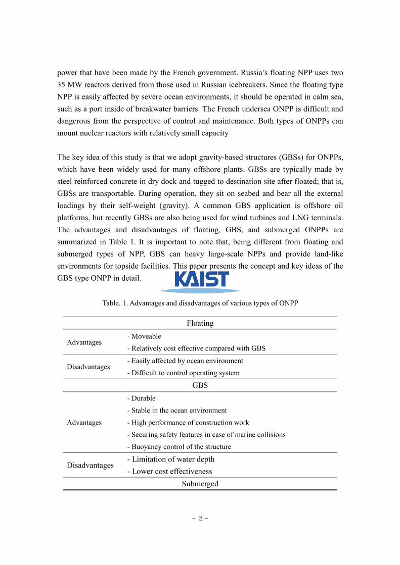
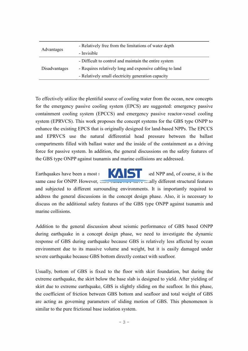
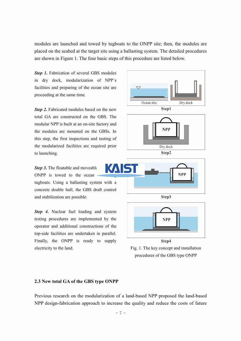
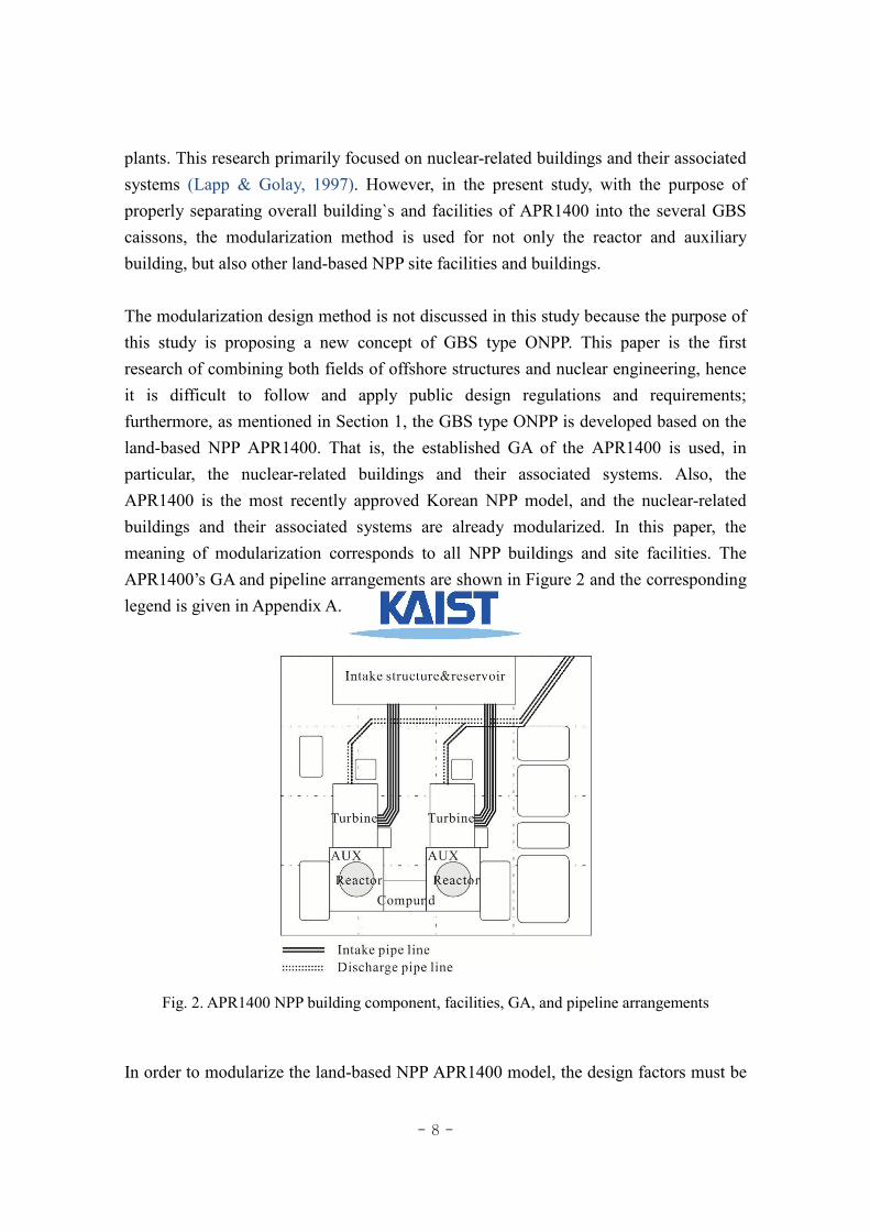
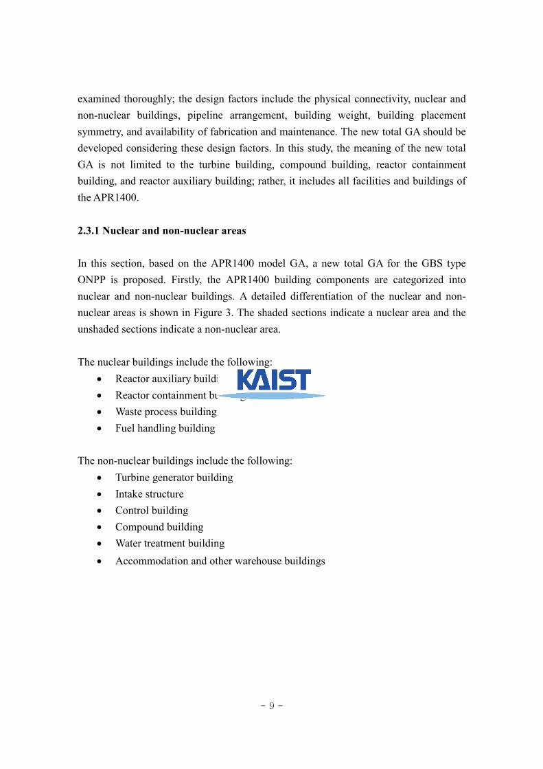
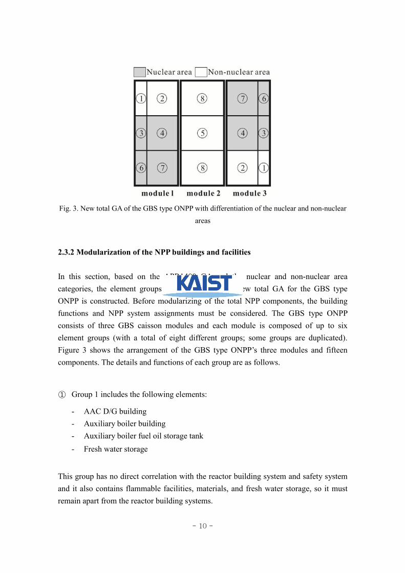
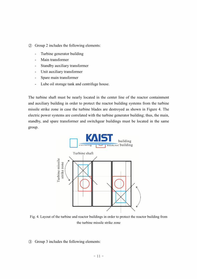
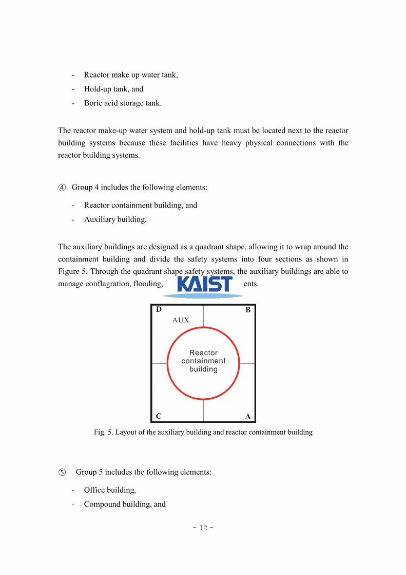
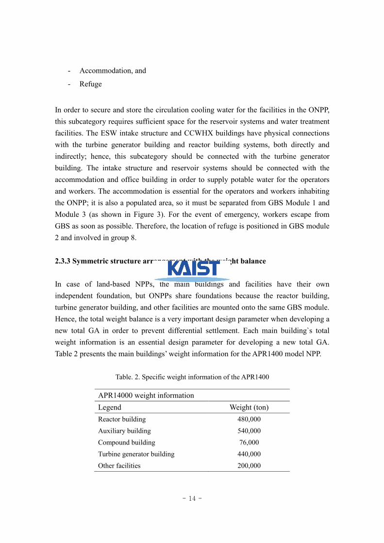
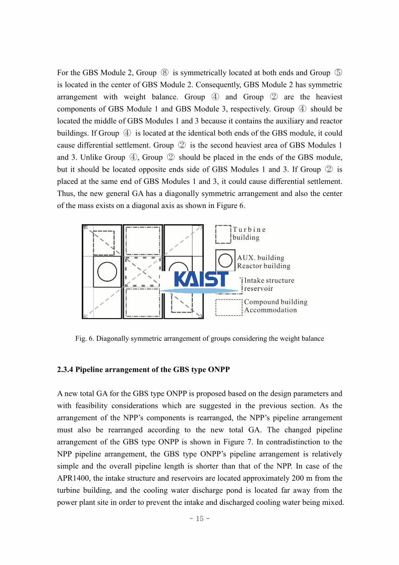
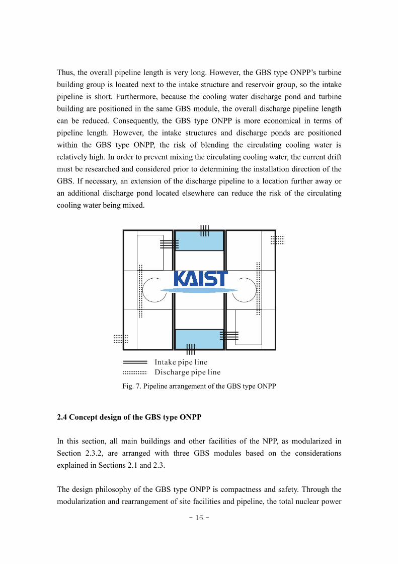
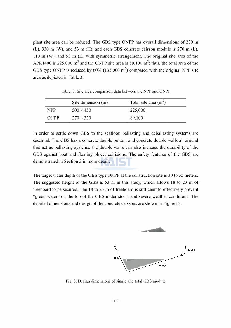
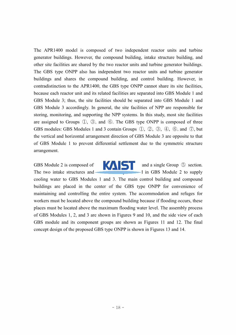

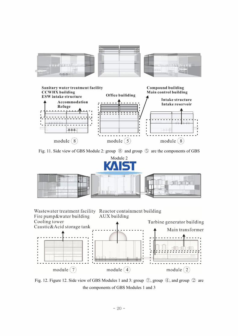

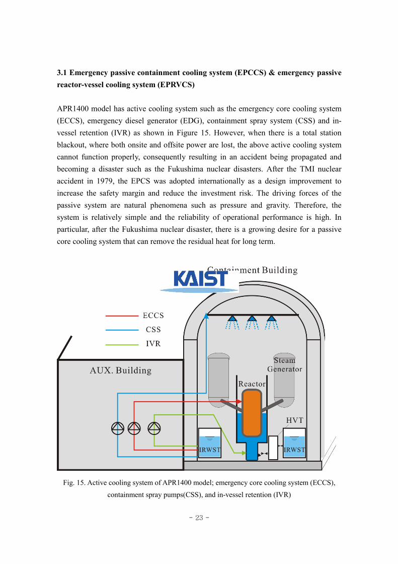
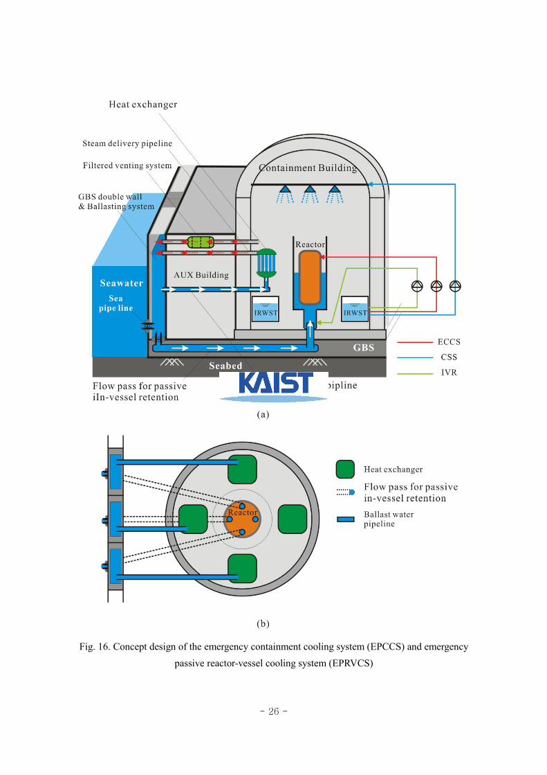
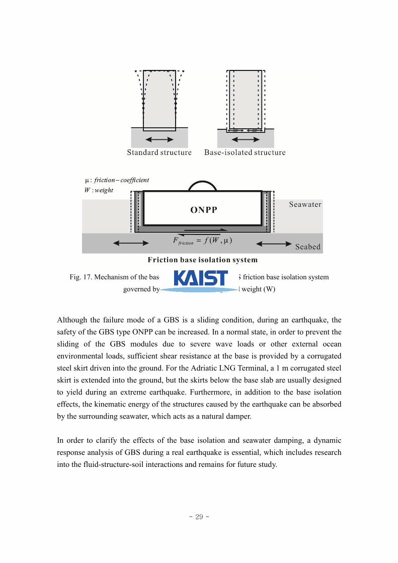
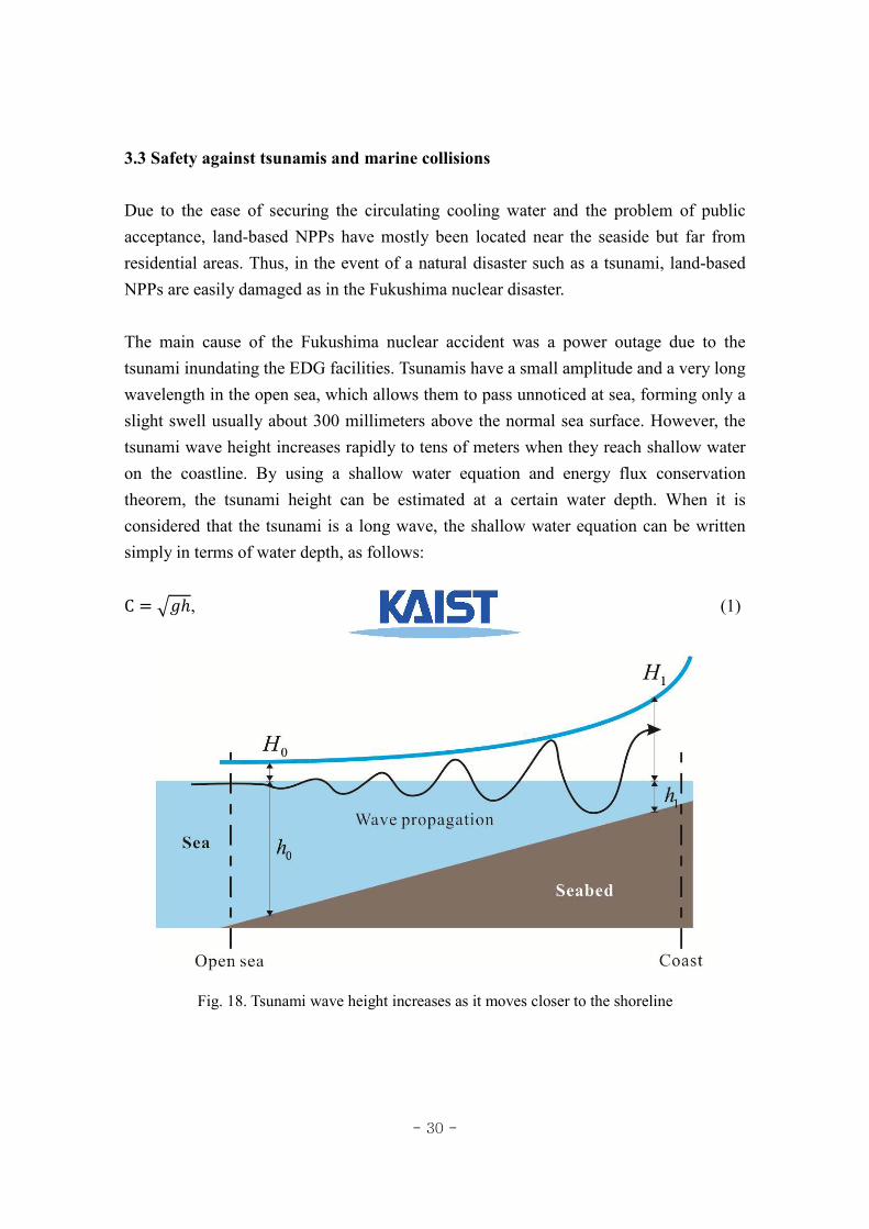
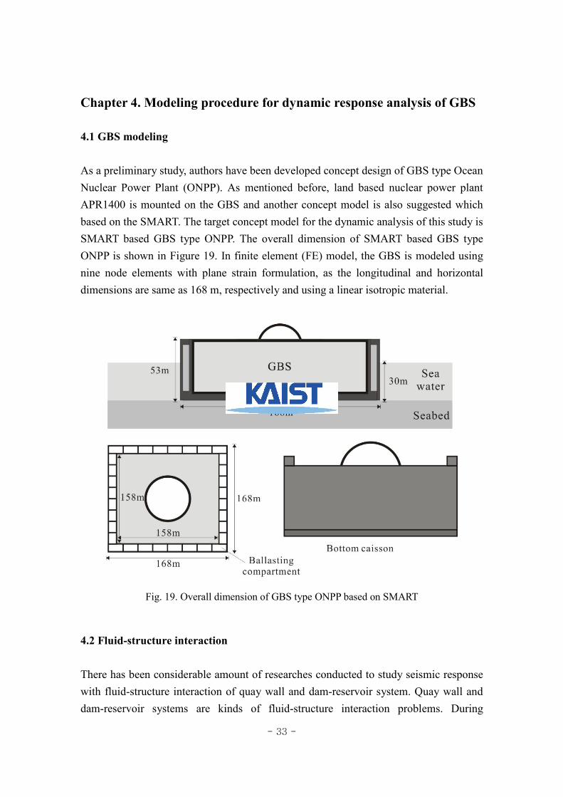
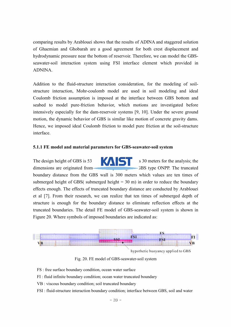
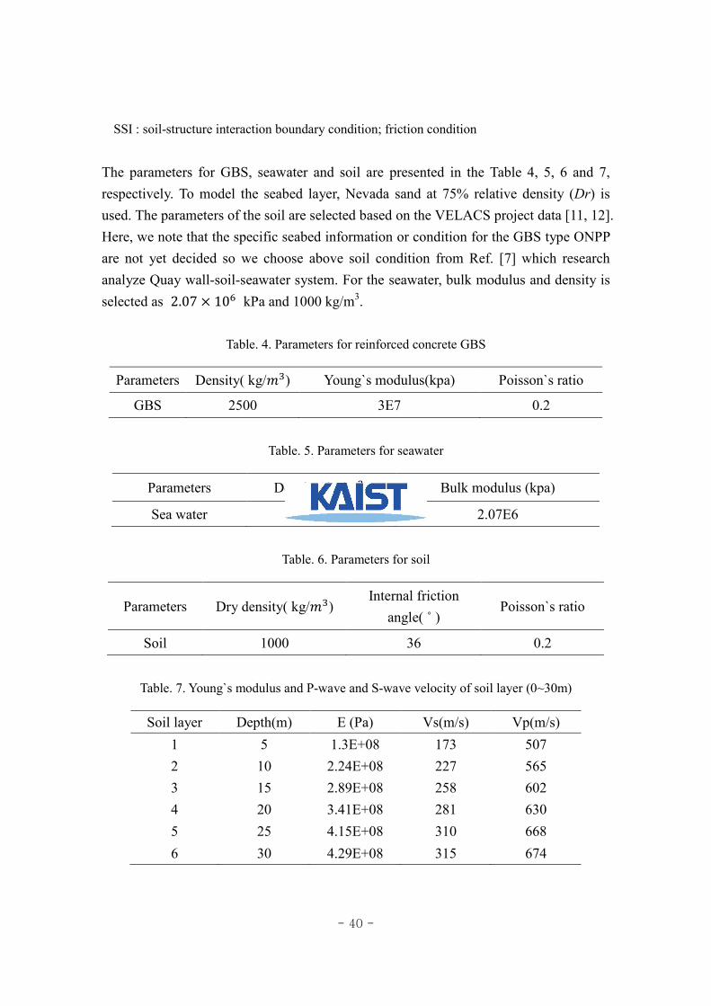
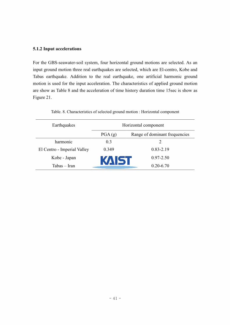
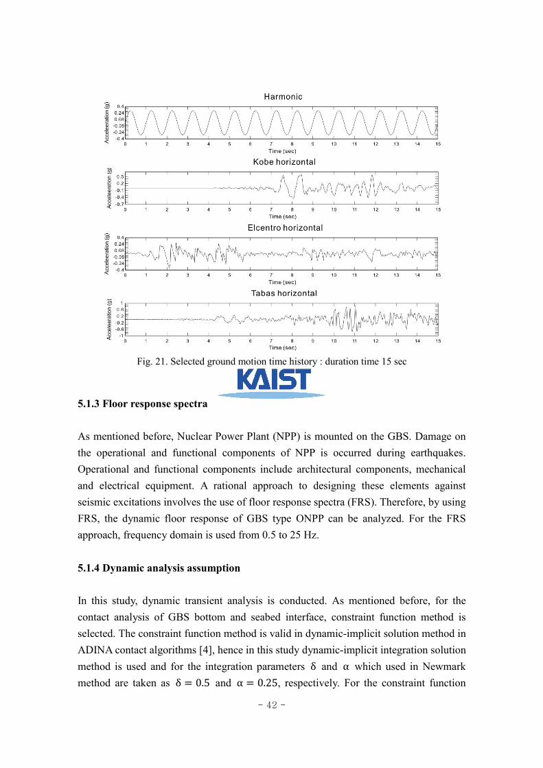
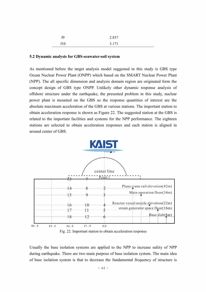
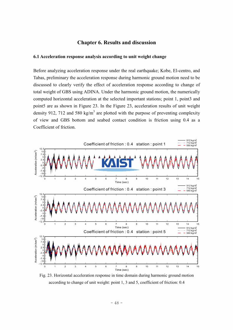
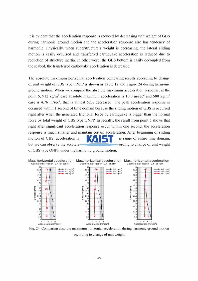
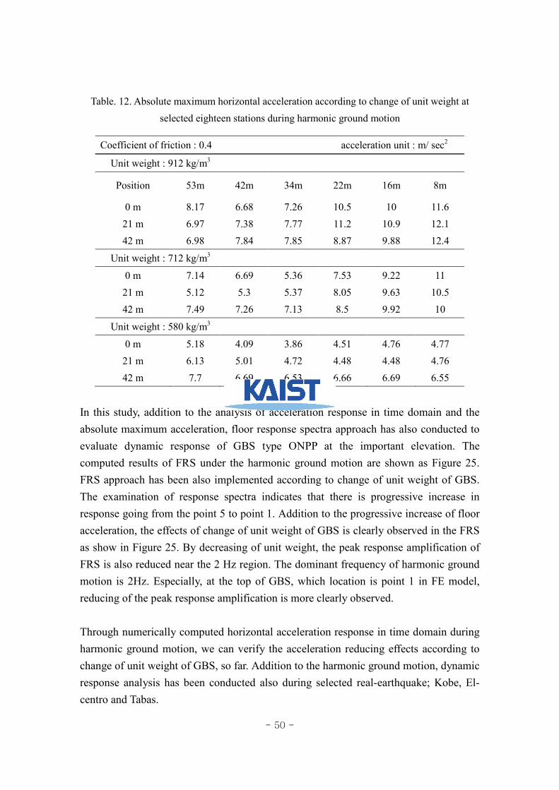
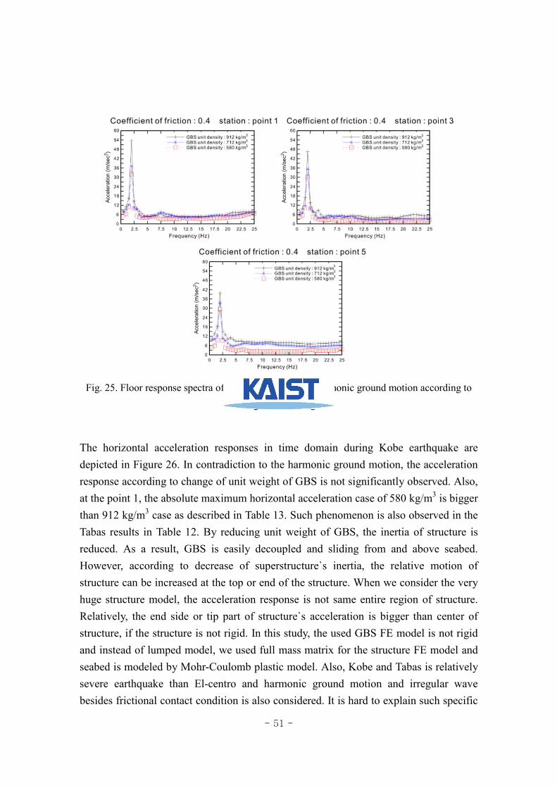
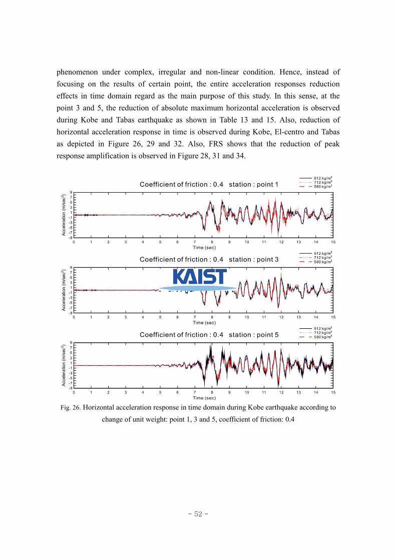
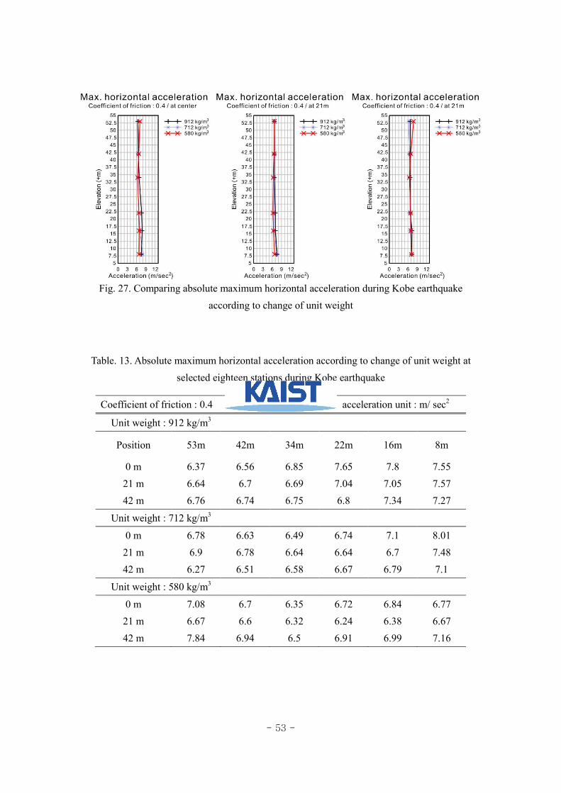

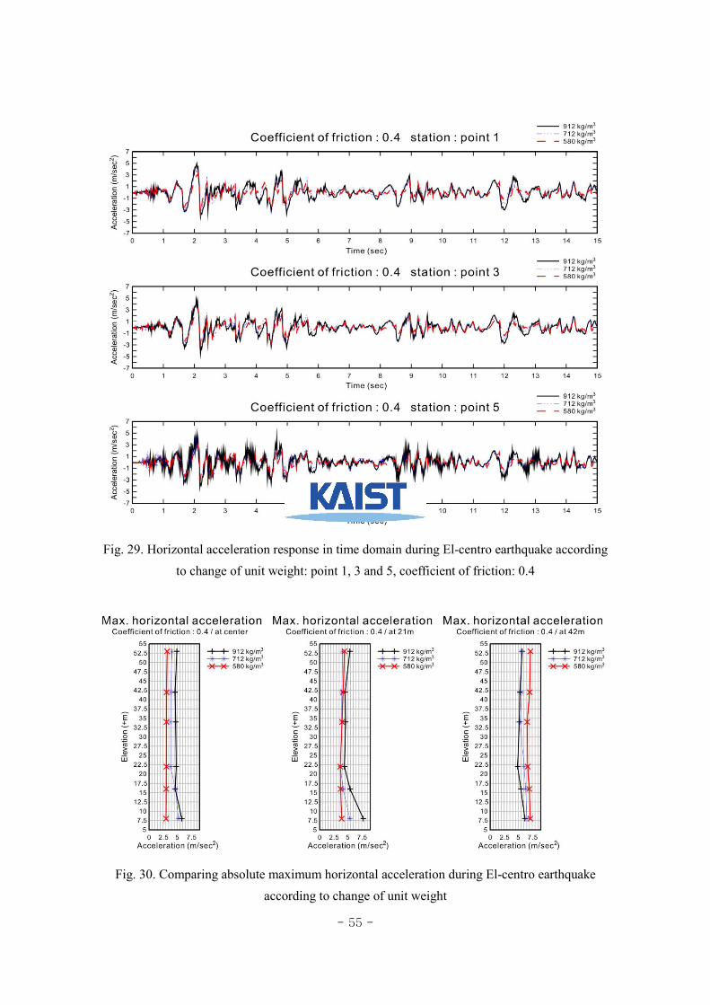
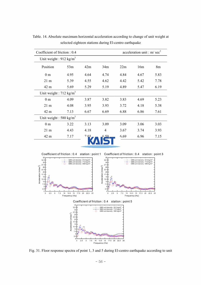
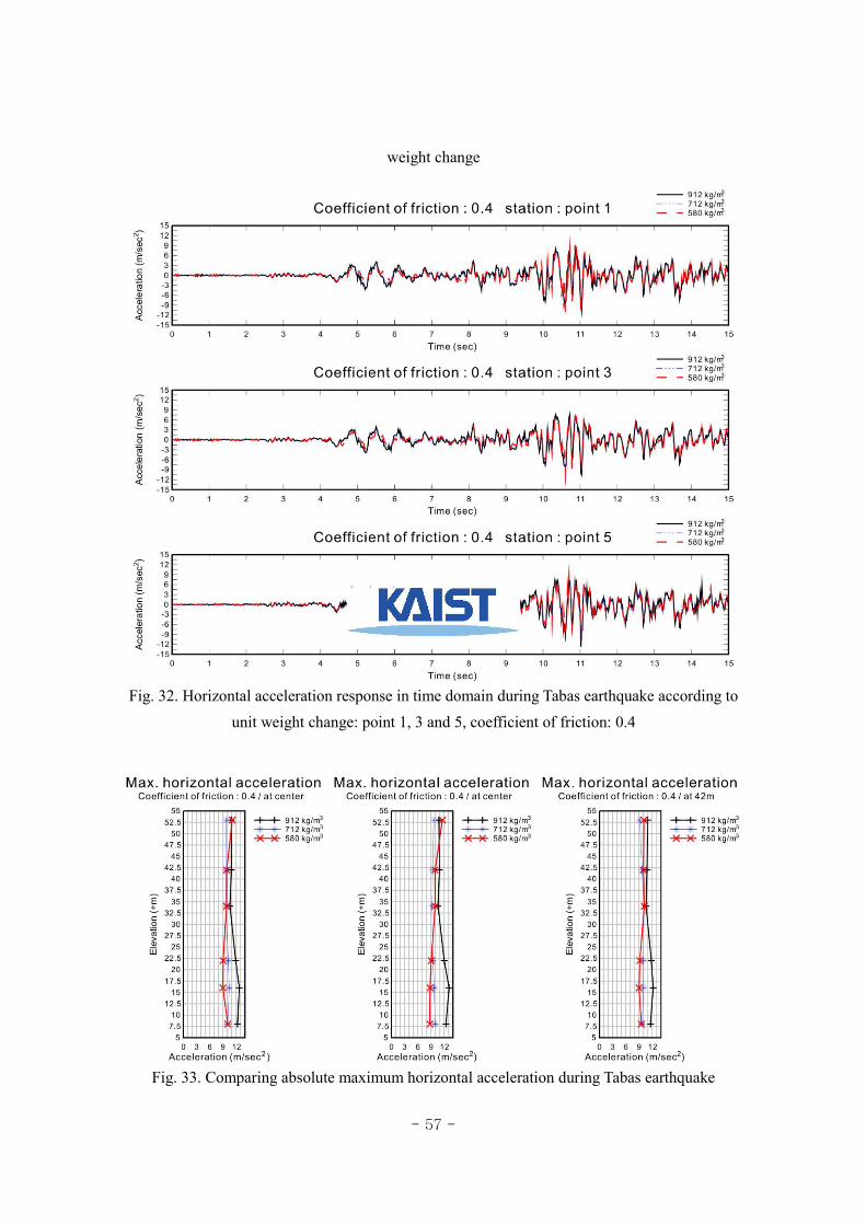
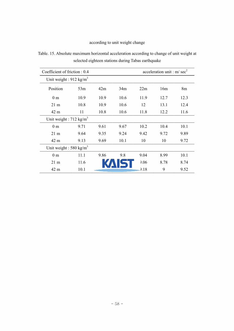
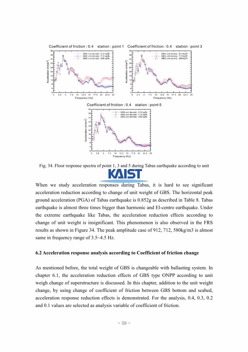
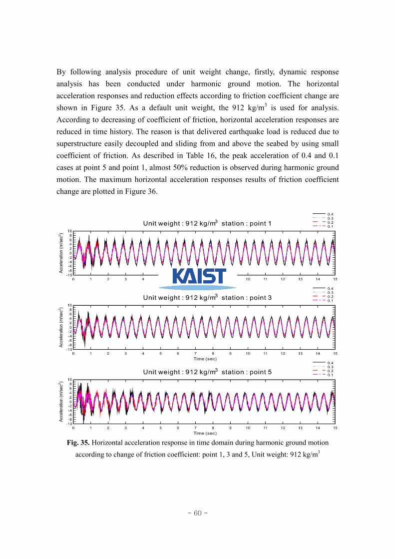
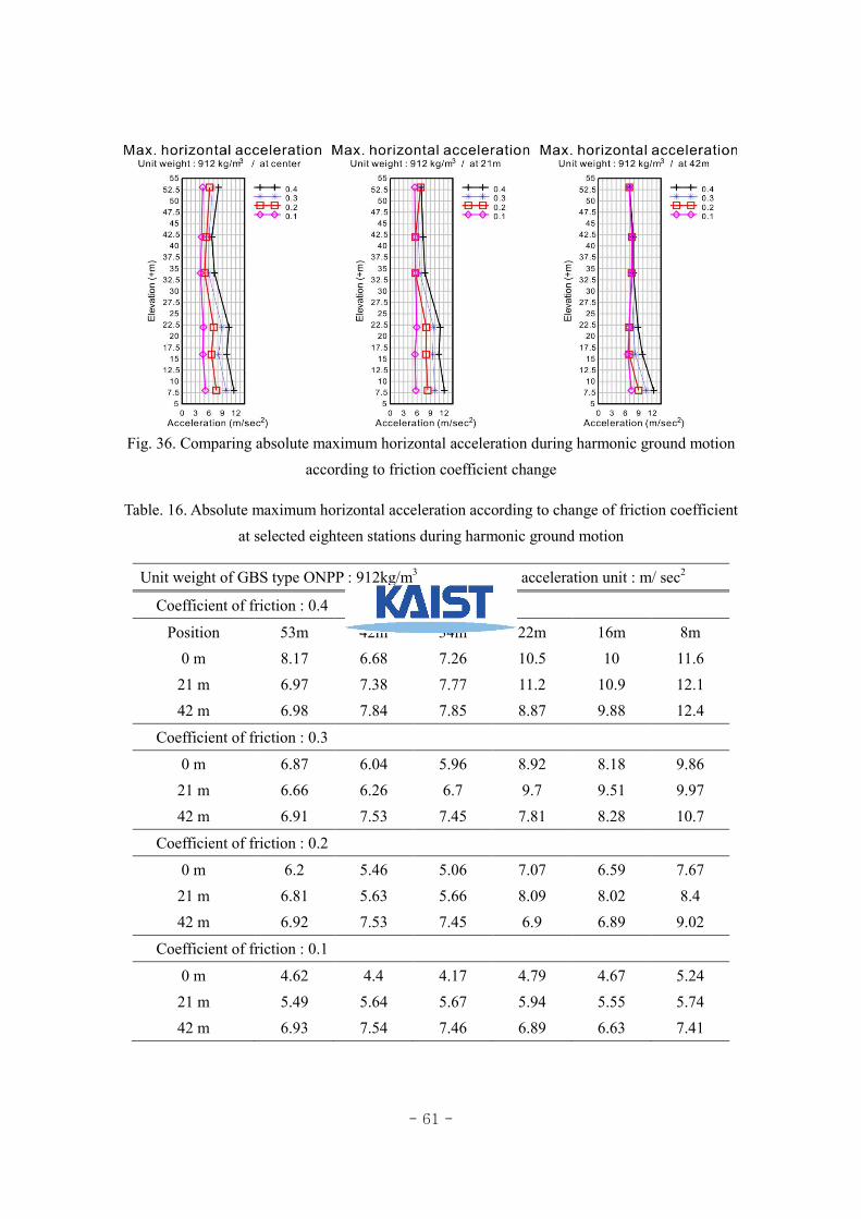
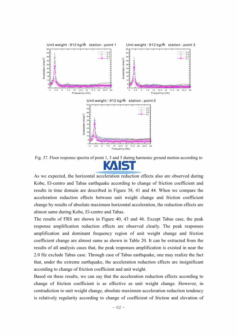
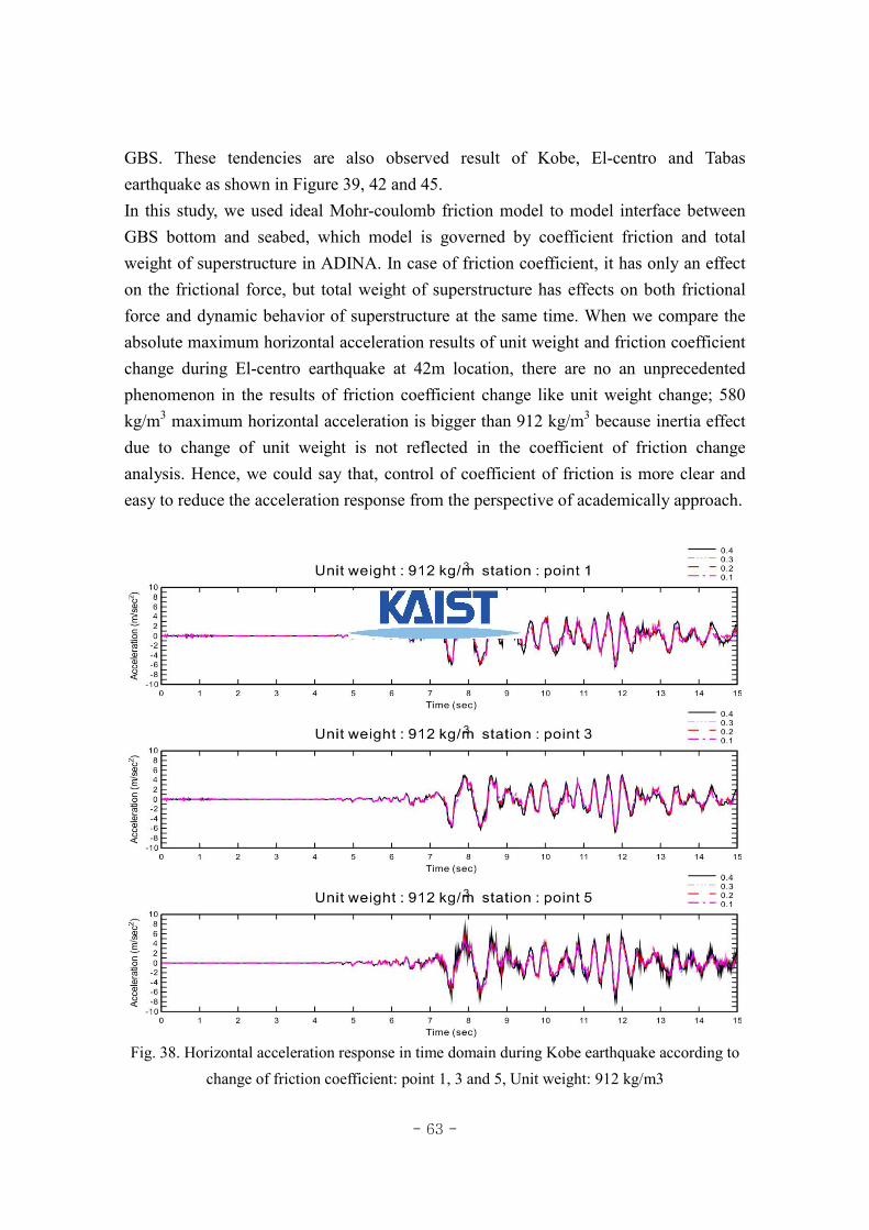
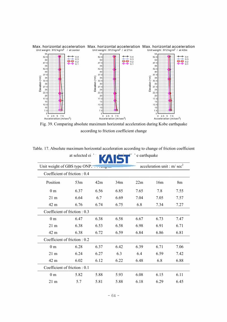
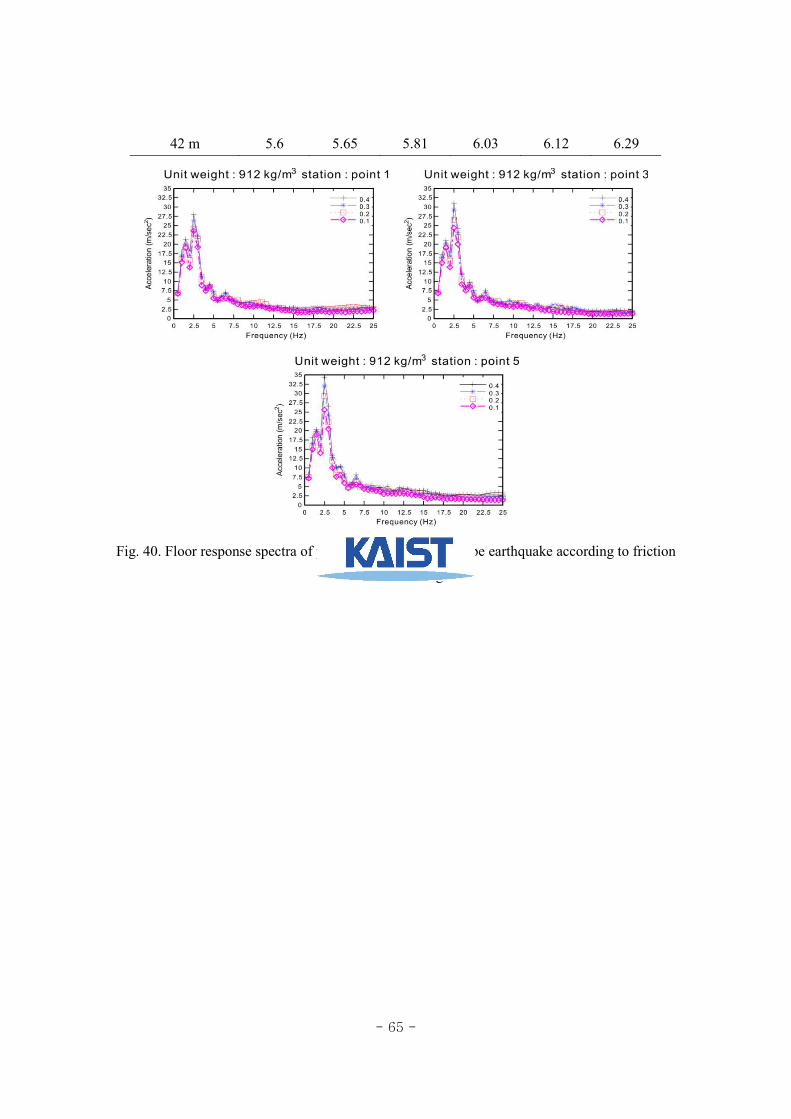
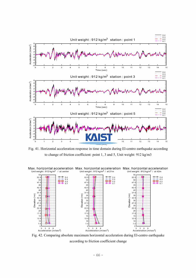
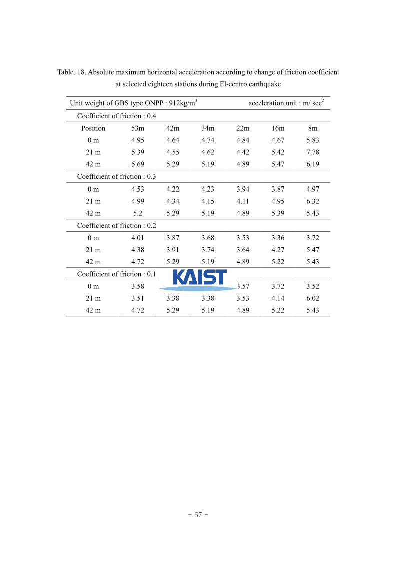
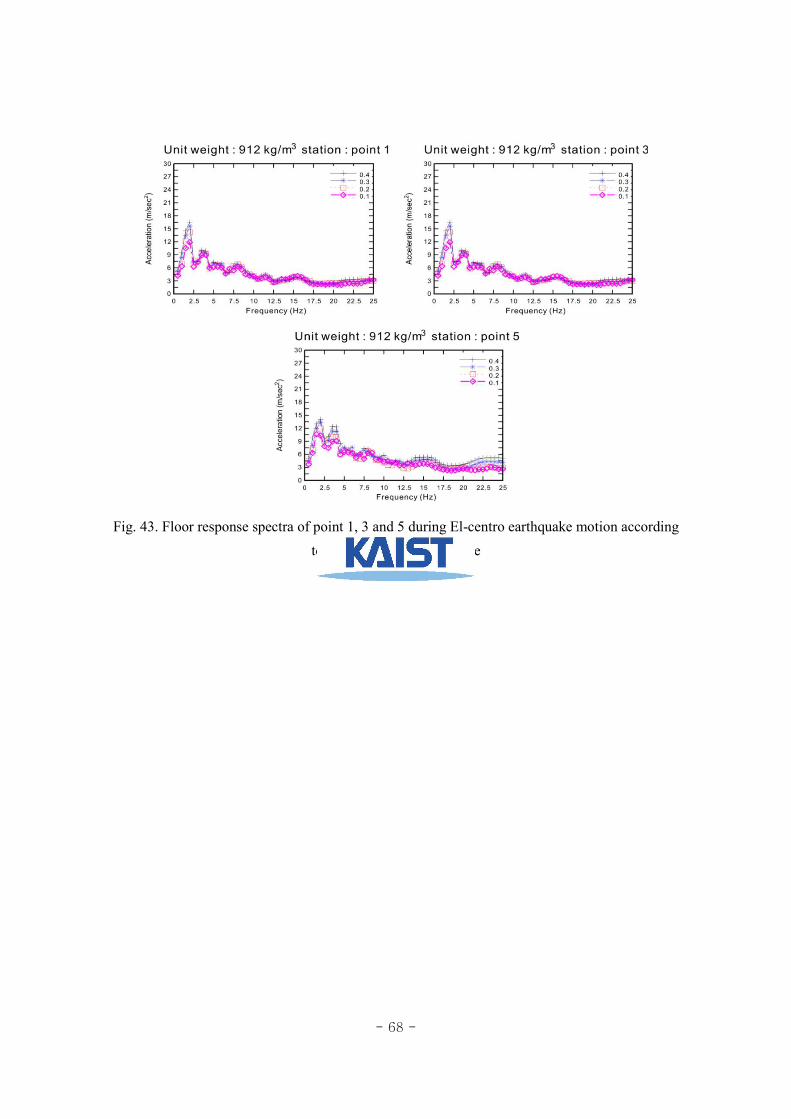
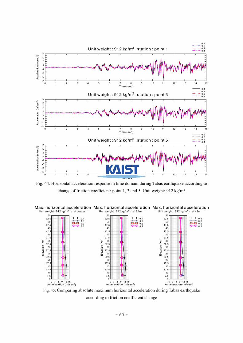
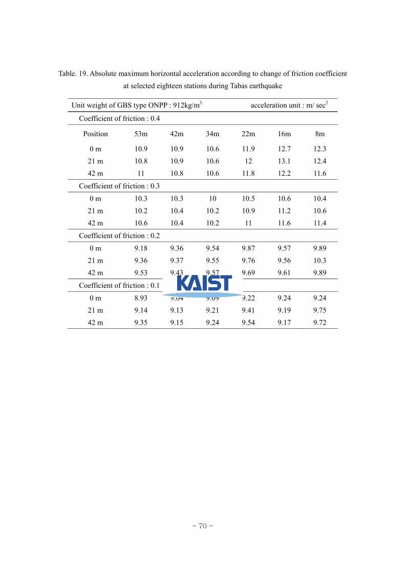
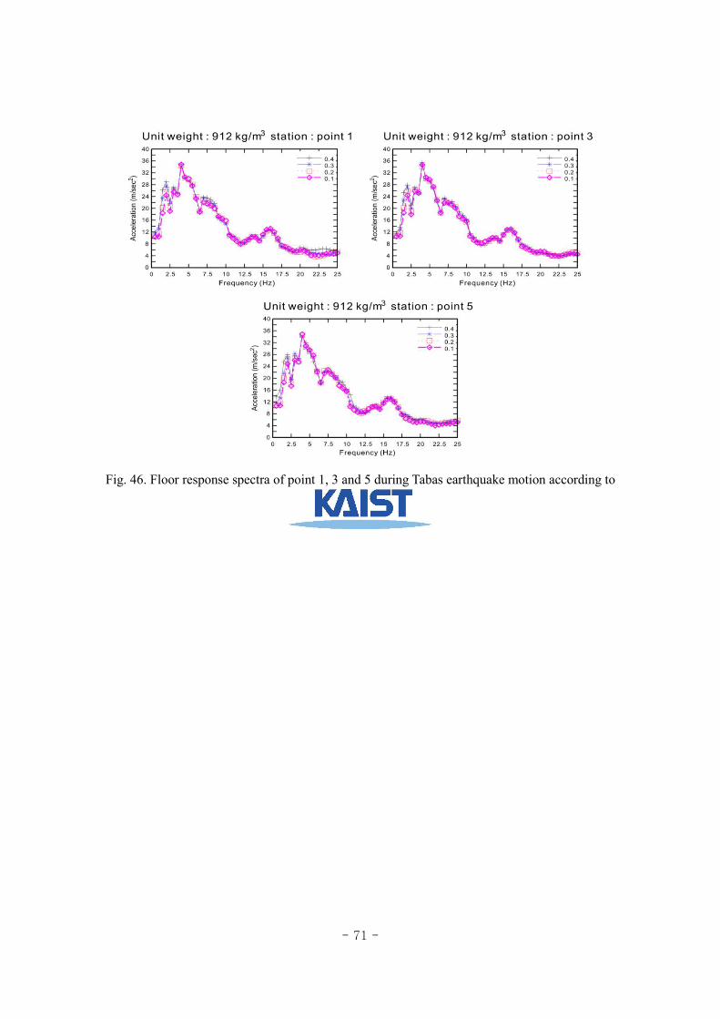
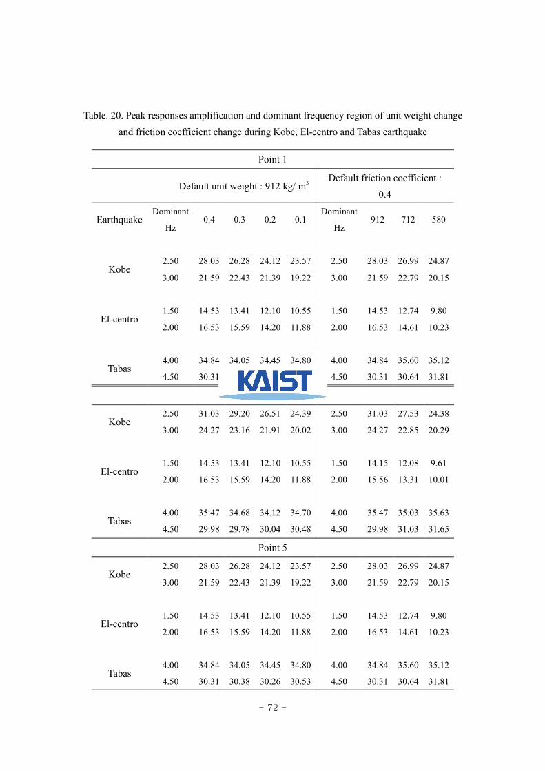
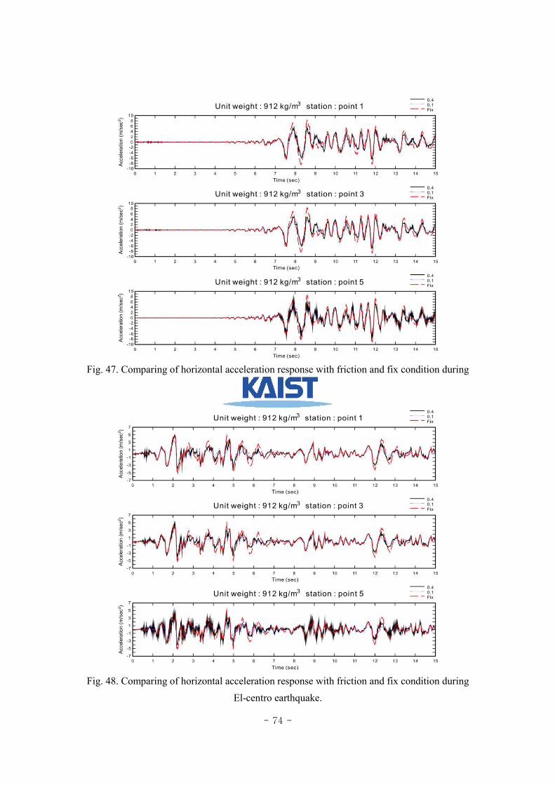
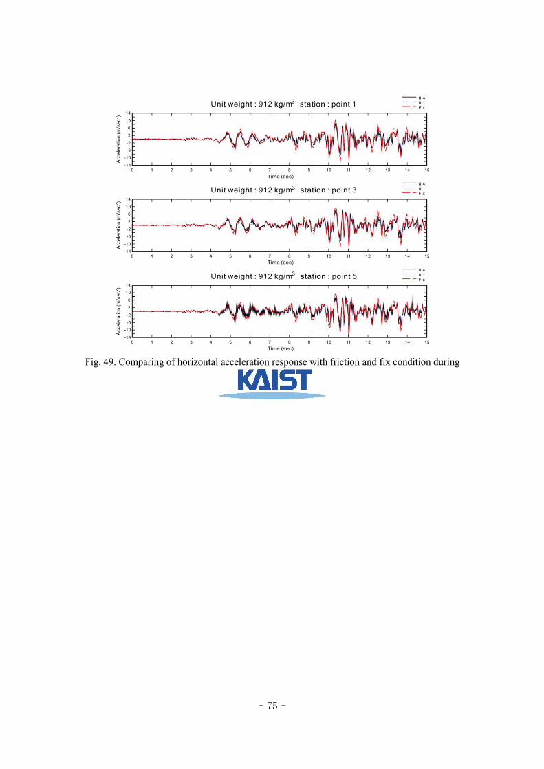


![최근국제금융시장동향 및 2012년전망 - kocham.kr · Choi Keun Hwan 1 [2011년11월 1일] 최근환[lifeiscool.choi@yahoo.co.kr] 최근국제금융시장동향 및2012년전망](https://img.pdfslide.tips/doc/110x75/5e2c8ac96cdede55e82fc4d4/oeeeoeeoeoee-e-2012ee-choi-keun-hwan-1-2011e11.jpg)


![Chol Hwan, Kang - Los acuarios de Pyongyang [R1].doc](https://img.pdfslide.tips/doc/110x75/55cf994a550346d0339c9f29/chol-hwan-kang-los-acuarios-de-pyongyang-r1doc.jpg)


![JONG HWAN KO (2019_03).pdf · [C23] Taesik Na, Burhan A. Mudassar, Priyabrata Saha, Jong Hwan Ko, and Saibal Mukhopadhyay, \Mixture of Pre-processing Experts Model for Noise Robust](https://img.pdfslide.tips/doc/110x75/5fc42b7c24897362e20252c8/jong-hwan-ko-201903pdf-c23-taesik-na-burhan-a-mudassar-priyabrata-saha.jpg)