Embed Size (px)
Citation preview
e+ ソースの現状
大森GDE 活動報告会
2008 年 6 月 23 日

そもそも ,,,
そもそもILC の e+ ソース
は難しい
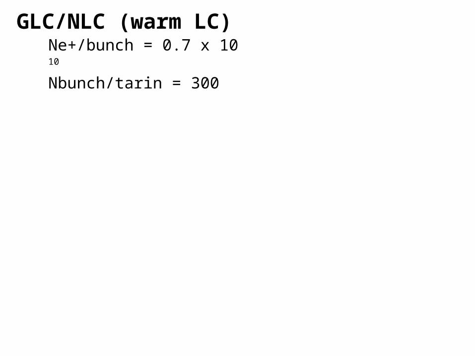
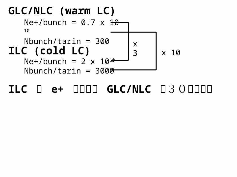
GLC/NLC (warm LC) Ne+/bunch = 0.7 x 10¹⁰
Nbunch/tarin = 300

GLC/NLC (warm LC) Ne+/bunch = 0.7 x 10¹⁰
Nbunch/tarin = 300
ILC (cold LC) Ne+/bunch = 2 x 10¹⁰
Nbunch/tarin = 3000

GLC/NLC (warm LC) Ne+/bunch = 0.7 x 10¹⁰
Nbunch/tarin = 300
ILC (cold LC) Ne+/bunch = 2 x 10¹⁰
Nbunch/tarin = 3000
x 3x 10
GLC/NLC (warm LC) Ne+/bunch = 0.7 x 10¹⁰
Nbunch/tarin = 300
ILC (cold LC) Ne+/bunch = 2 x 10¹⁰
Nbunch/tarin = 3000
x 3x 10
ILC の e+ ソースは GLC/NLC の30倍難しい

GLC/NLC (warm LC) Ne+/bunch = 0.7 x 10¹⁰
Nbunch/tarin = 300
ILC (cold LC) Ne+/bunch = 2 x 10¹⁰
Nbunch/tarin = 3000
x 3x 10
ILC の e+ ソースは GLC/NLC の30倍難しい
これはかなり乱暴なステートメントGLC/NLC: パルス長 = 1 micro sec
ILC : パルス長 = 1 m sec

GLC/NLC (warm LC) Ne+/bunch = 0.7 x 10¹⁰
Nbunch/tarin = 300
ILC (cold LC) Ne+/bunch = 2 x 10¹⁰
Nbunch/tarin = 3000
x 3x 10
ILC の e+ ソースは GLC/NLC の30倍難しい
これはかなり乱暴なステートメントGLC/NLC: パルス長 = 1 micro sec
ILC : パルス長 = 1 m sec
ILC の e+ ソースの実現 --> パルス長 1 m sec を生かす ---> 超高速 100 〜 200 m/sec で回転するターゲット

GLC/NLC (warm LC) Ne+/bunch = 0.7 x 10¹⁰
Nbunch/tarin = 300
ILC (cold LC) Ne+/bunch = 2 x 10¹⁰
Nbunch/tarin = 3000
x 3x 10
ILC の e+ ソースは GLC/NLC の30倍難しい?ターゲットの難しさを比較してみる
GLC コンベンショナル ( ドライブ beam --> e- beam) ターゲットを3つ使う設計 ILC (base line) アンジュレーター (high K) ( ドライブビーム --> ガンマ) ターゲットの熱負荷( und / conv = 1/3 by Clarke さん) ターゲット一つでかつ回転が遅いと GLC の10倍厳しい 超高速 (100 〜 200 m/sec) 回転ターゲット

GLC/NLC (warm LC) Ne+/bunch = 0.7 x 10¹⁰
Nbunch/tarin = 300
ILC (cold LC) Ne+/bunch = 2 x 10¹⁰
Nbunch/tarin = 3000
x 3x 10
ILC の e+ ソースは GLC/NLC の30倍難しい?ターゲットの難しさを比較してみる
GLC コンベンショナル ( ドライブ beam --> e- beam) ターゲットを3つ使う設計 ILC (base line) アンジュレーター (high K) ( ドライブビーム --> ガンマ) ターゲットの熱負荷( und / conv = 1/3 by Clarke さん) ターゲット一つでかつ回転が遅いと GLC の10倍厳しい 超高速 (100 〜 200 m/sec) 回転ターゲット <-- 予期せぬ問題発生 ( 後述 )
Base LineHelical Undulator based
Unpolarized Source
あまり前進していないので、昨年の報告会 (2007/10/29 by 大森 ) の復習が主です

BCD (December 2005)
Undulator は主リナックの途中 (150 GeV at Phase 1, phase 2 ??? 記述なし )
Undulator 長 最初 100 m (active length)(unpolarized) 後で 100 m 追加 (polarized 60%)
Target Ti Rotation tangential speed 100m/sec
作った e+ beam は IP を超えて反対側の端にある e+ DR へ
主リナックの終わり --> 主リナックの途中 に変更した理由はECM = 300 GeV - 500 GeV の運転に対応する為ECM < 300 GeV への対応 ( 重要 low mass Higgs, Z-pole) 記述なし、減速運転を暗黙のうちに仮定

RDR (August 2007) Undulator は主リナックの途中 ( 変更なし ) (150 GeV at Phase 1, phase 2 ??? 記述なし )
Undulator 長 最初 147 m (active length)(unpolarized)(BCD x 1.5 倍 ) 呼び値は unpolarized だが実は 30 % polarized 後で ??? m 追加 (polarized 60%) 記述なしTarget Ti( 変更なし ) Rotation tangential speed 100m/sec( 変更なし )
作った e+ beam は 中央の e+ DR へ ( トランスポートが短くなった )
主リナックの終わり --> 主リナックの途中 に変更した理由はECM = 300 GeV - 500 GeV の運転に対応する為ECM < 300 GeV への対応 ( 重要 low mass Higgs, Z-pole) 記述なし、減速運転を暗黙のうちに仮定
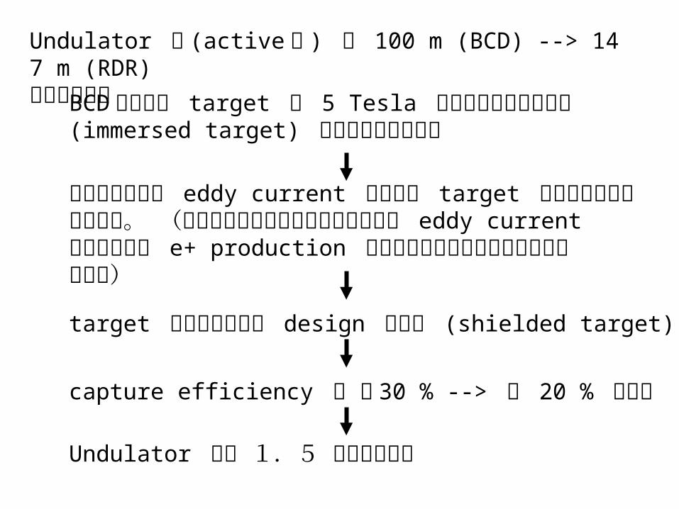
Undulator 長 (active 長 ) が 100 m (BCD) --> 147 m (RDR)と伸びた理由BCD 時点では target は 5 Tesla の磁場に浸かっている
(immersed target) と仮定されていた。
しかしそれでは eddy current のために target が回転できない事が判明。 (無理やりに回転できると仮定すると eddy currentによる発熱が e+ production による発熱の1ケタ以上多くなると判明)target 上に磁場が無い design に変更 (shielded target)
capture efficiency が 〜 30 % --> 〜 20 % に低下
Undulator 長を 1.5 倍に伸ばした

RDR (August 2007) 続き2
Undulator chicane insert 1257 m
undulator insert 200 m
offset 2.5 m
150 GeV 地点
target
500 m
400 MeV e- linac
line
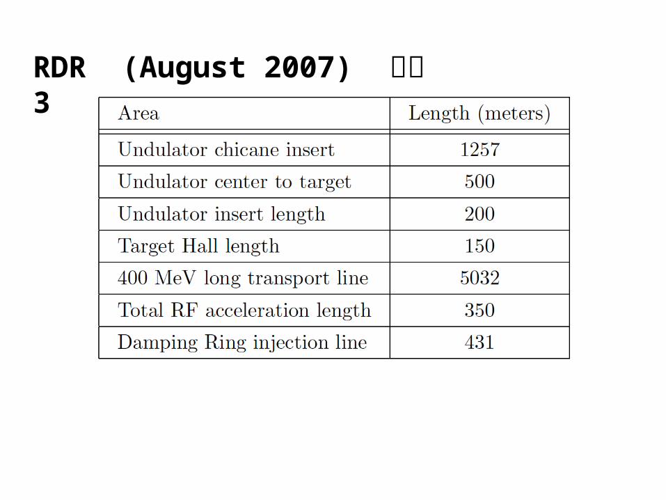
RDR (August 2007) 続き3
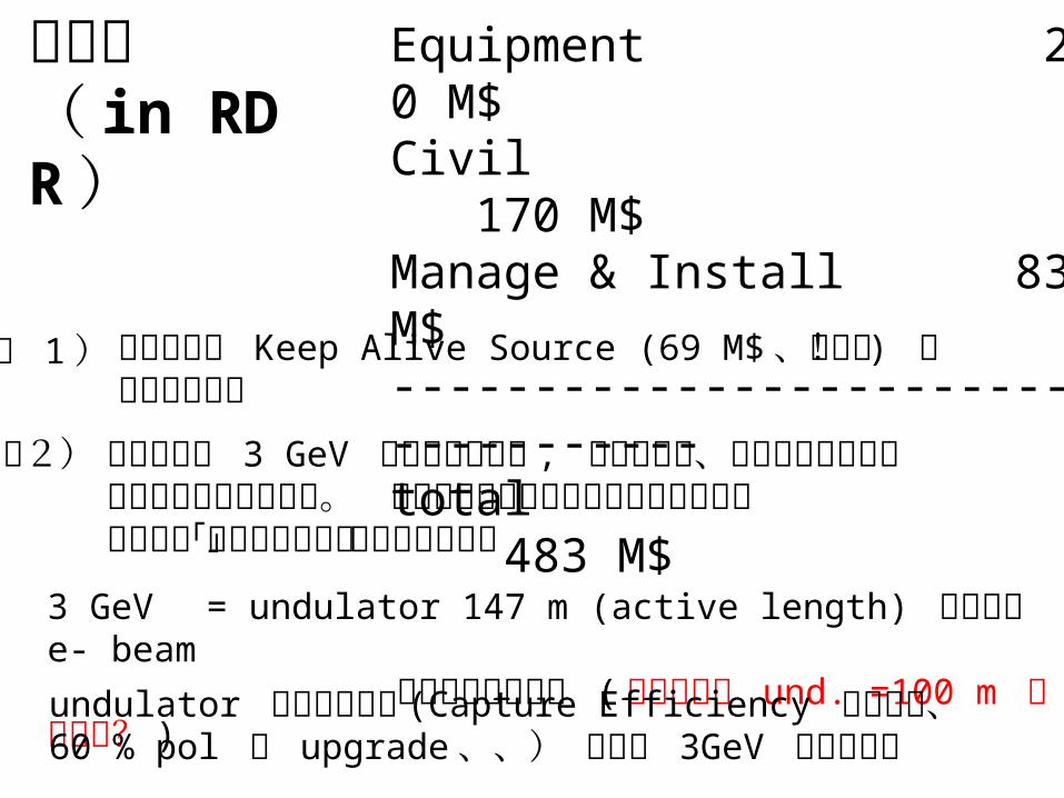
コスト( in RDR )
Equipment 230 M$Civil 170 M$Manage & Install 83 M$------------------------------------total 483 M$
この中には 3 GeV 分の主リナック , 同トンネル、同クライストロンなどは含まれていない。 主リナックのコストに含まているハズある意味「隠れたコスト」になる恐れあり3 GeV = undulator 147 m (active length) 通過時の e- beam
のエネルギーロス ( 要チェック und. =100 m での計算? )
注2)
undulator が長くなれば (Capture Efficiency がさがる、60 % pol に upgrade 、、) ロスは 3GeV 以上となる
この中には Keep Alive Source (69 M$ 、高い! ) が含まれている
注 1 )
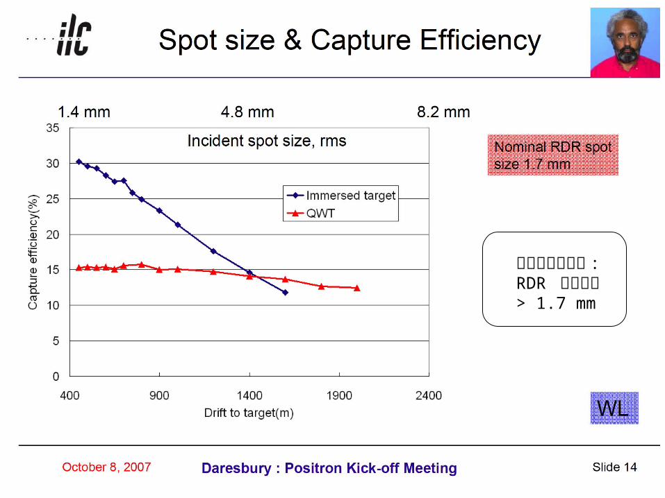
大森による注釈 :RDR での値は> 1.7 mm

Jeff Gronberg/ LLNLPosiPol2008
赤四角は大森による

Undulator --> Target 間は 500 m のままで良いのか

by Wanming & Wei

ILC のベースライン (high K undulator) はガンマ・ベースの陽電子源なのに、なぜかくもターゲット上のエネルギー deposit が厳しいのか?
1. 1st harmonic は population としては圧倒的大多数 であるが、陽電子生成 (capture されて有効利用される e+)
には、 たった5%しか寄与していない (この後2枚のスライド参照) しかし、ショックウエーブと熱は発生させる。
2.メインリナックの電子ビームを使うという制約の為に、 1 m sec の間に 3000 bunches を作る必要がある。 手持ち時間は 200 m sec - damping time 〜 10-100 m sec もあるにもかかわらず、、、、

by Wanming & Wei
大森による追記: 1st harmonic photon が 圧倒的多数 ( あたりまえだが )

by Wanming & Wei
大森による追記: 1st harmonic photon の e+ 生成 (capture されて有効利用される e+) への寄与は 5 % 程度

Undulator chicane insert 1257 m
undulator insert 200 m
off set 2.5 m
150 GeV 地点 (Ecm = 500 GeV の時 ) -> エミッタンス増加は無視できる400 GeV 地点 (Ecm = 1000 GeV の時 ) -> エミッタンス増加 = 400%

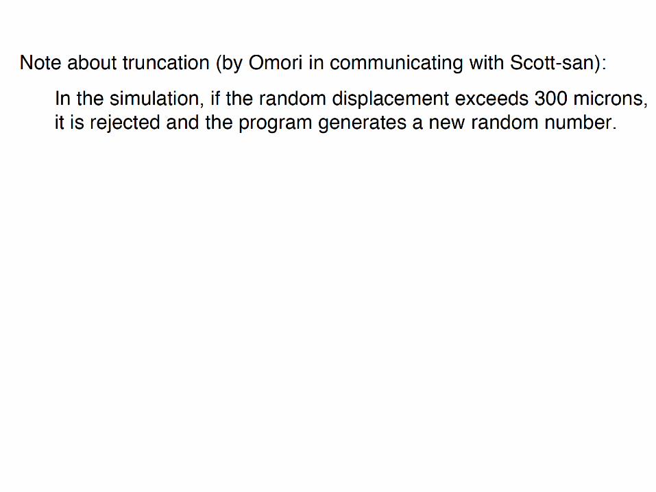

参考 Beam Dynamics グループの人たちが主リナック等で 仮定しているアライメント・エラー (rms) 。 truncation は仮定した rms の3倍でおこなっている。
「水平面内のエラー〜(3 5)− x垂直面内のエラー」と仮定
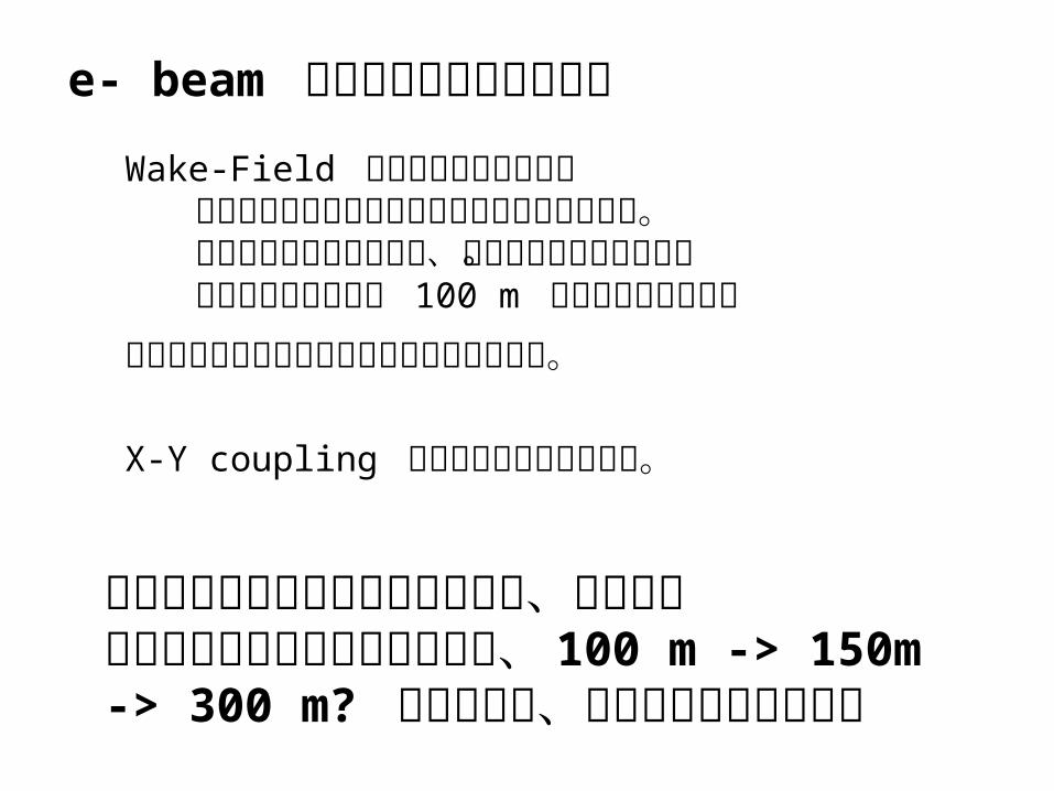
e- beam エミッタンス増大の懸念
Wake-Field の分は計算されている ただしミスアライメントの仮定が楽観的すぎる。 アンジュレーターの傾き、曲がりは入っていない。 アンジュレーター長 100 m でシミュレーションシンクロトロン放射の分は計算されていない。
X-Y coupling の分は計算されていない。
致命的ではないと思われているが、アンジュレーターの長さが増大している、 100 m -> 150m -> 300 m? こともあり、慎重なチェックが必要
N. Walker e+ KOM (2007)
赤四角は大森による


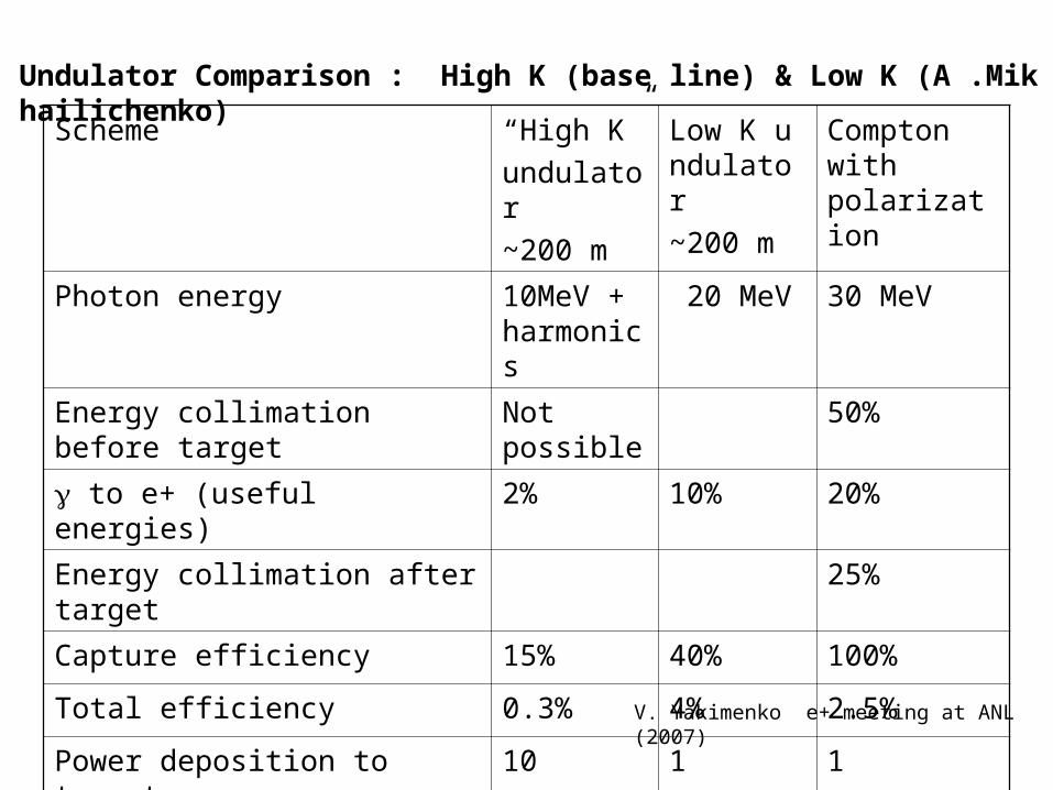
Scheme “High K”
undulator
~200 m
Low K undulator
~200 m
Compton with polarization
Photon energy 10MeV + harmonics
20 MeV 30 MeV
Energy collimation before target Not possible
50%
to e+ (useful energies) 2% 10% 20%
Energy collimation after target 25%
Capture efficiency 15% 40% 100%
Total efficiency 0.3% 4% 2.5%
Power deposition to target 10 1 1
Undulator Comparison : High K (base line) & Low K (A .Mikhailichenko)
V. Yakimenko e+ meeting at ANL (2007)

M. Ross e+ meeting Zeuthen April 2008
赤四角は大森による
Wei Gai, CCAST ILC meeting, Beijing, Nov/2007
赤四角は大森による

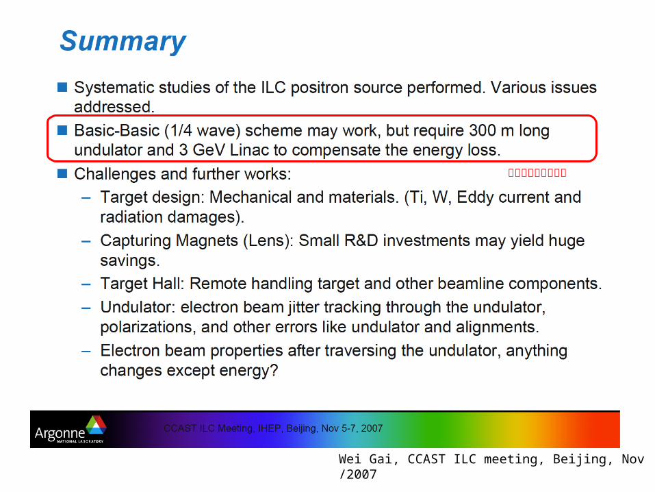
今のところ最大の問題は Ready-to-Constructに一番近く、かつコンシステントなパラメーターセット(デザイン)が存在しないこと。
・アンジュレーター長 = 300 m (RDR は 150 m)
・1/4波長マッチング (RDR はフラックスコンセントレーター )
・アンジュレーター to ターゲット = 500 m + アルファ (RDR は 500 m)
・Main Linac の energy 低下 = 6 GeV (RDR は 3 GeV) <-- これはアンジュレーター長 147 m 相当 のハズ ( この点、要チェック ) なので 300 m なら 6 GeV
大森が考えるところ (Wei さん他が言っている事とほぼ同じだ
が ) 、今一番 " もっともらしい " のは

Alternative (a)Conventional Source

Alternative (a)Conventional Source
今となっては Advanced Conventional Source
というべきか

The 300 Hz Conventional
e+ Source w/ Liquid Lead Target
Advanced e+ source
Junji Urakawa (KEK)
Present members : T. Omori (KEK), J. Urakawa (KEK), M. Kuriki (Hiroshima Univ.),T. Takahashi (Hiroshima Uni
v.), Pavel Logachev (BINP, Novosibirsk)
High possibility to make reliable target system using liquid lead target and S-band linac as
one of advanced e+ source for ILC.
J. Urakawa, GDE meeting Dubna June/2008

Question: Can Liquid Lead Target (& BN window) survive the 3000-bunch-creation in 1 m sec?
Answer: No BN window is OK against shock wave. However, BN window is broken by heat. Lead evaporate.
Solution: e+ Creation in 100 m sec --> 100 bunches/train x 300 Hz BN window is OK for 100 bunches. Lead dose not evaporate with 100 bunches. Lead move 33 mm in 3.3 msec, then heat is removed. (speed of lead = 10 m/sec, 300 Hz <--> Tt_to_t = 3.3 m sec ドライブビームは 6 GeV 程度の e- beam (主リニアックとは独立)
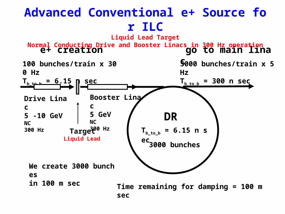
100 bunches/train x 300 HzTb_to_b = 6.15 n sec
DRTb_to_b = 6.15 n sec
3000 bunches/train x 5 HzTb_to_b = 300 n sec
e+ creation go to main linac
Time remaining for damping = 100 m sec
We create 3000 bunches in 100 m sec
Booster Linac5 GeV NC300 Hz
Drive Linac5 -10 GeV NC300 Hz
TargetLiquid Lead
Advanced Conventional e+ Source for ILCLiquid Lead Target
Normal Conducting Drive and Booster Linacs in 300 Hz operation
3000 bunches
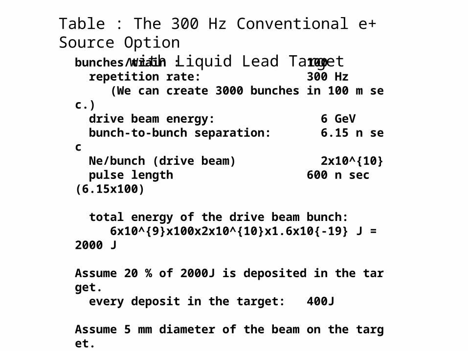
bunches/train : 100 repetition rate: 300 Hz (We can create 3000 bunches in 100 m sec.) drive beam energy: 6 GeV bunch-to-bunch separation: 6.15 n sec Ne/bunch (drive beam) 2x10^{10} pulse length 600 n sec (6.15x100)
total energy of the drive beam bunch: 6x10^{9}x100x2x10^{10}x1.6x10{-19} J = 2000 J
Assume 20 % of 2000J is deposited in the target. every deposit in the target: 400J
Assume 5 mm diameter of the beam on the target. Weight of the target : 2 g = 0.0056 Kg (2.5x2.5x3.14x28x11gx10x{-3} = 5.6 g)
delta T: delta T = 400J / (140J/K*Kg) / 0.0056 Kg = 510 K
Table : The 300 Hz Conventional e+ Source Optionwith Liquid Lead Target

The conventional e+ source with the liquid lead target seems OK for ILC. condition: We need 300 Hz operation of the drive beam and the injector.
Summary of consideration of Liquid target for ILC
Are assumptions really OK? For example "BN window is OK for 100 bunches.,,, Lead move 33 mm in 3.3 msec, then heat is removed. " <--- ?? Need the test of BN window and liquid lead target with KEKB beam. Small hall is necessary.
Mini-bunch train: 100 bunches/pulse (50 to 200 bunches/pulse)
Require about 14msec damping time (3km double ring or increase damping wigglers)

Crystal + Amorphous Hybrid Target Option

Crystal + Amorphous Hybrid Target Option
channeling gamma generation
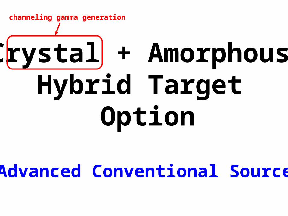
Crystal + Amorphous Hybrid Target Option
channeling gamma generation
Advanced Conventional Source

四角は大森
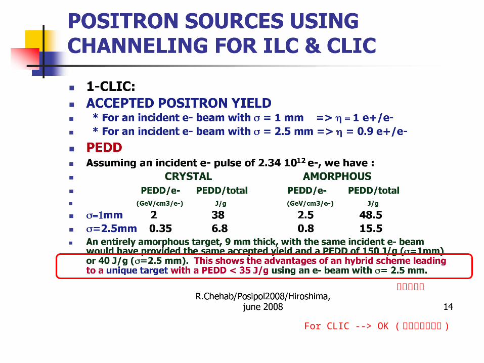
四角は大森
For CLIC --> OK ( 大森による追記 )

四角は大森
For LIC --> Not OK ( 大森による追記 )
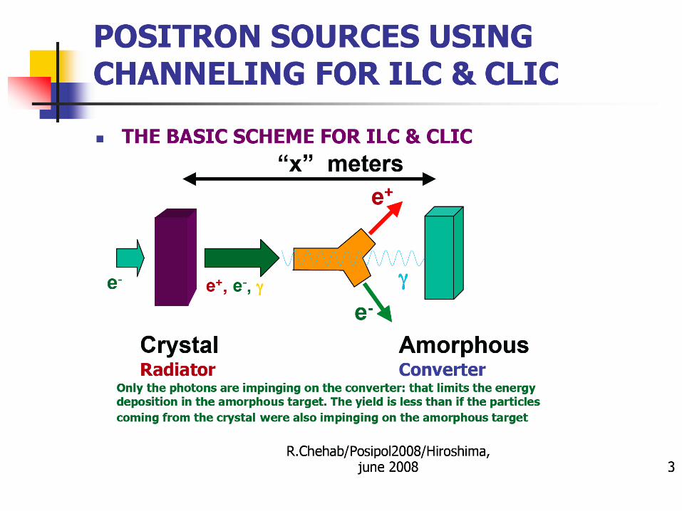
"Crystal + Amorphous" Hybrid Targetdriven by e- beam
Chehab さんの結論 (1) CLIC 用には OK (2) ILC 用には Not OK
ほんとうにそうか?ILC 用には Not OK

ほんとうにそうか?ILC 用には Not OK
よく考えると結論は ILC 用には ??? (結論ナシ ) 3000 bunches at once には Not OK

解 "100 bunches/pulse x 300 Hz" がある
0.33 J/g/bunch x 100 bunches= 33 J/g< 35 J/bunch = limit
Chehab さんの計算が正しいなら、Hybrid (= Crystal + Amorphous) Target は 100 bunches at once に耐える。

100 bunches/train x 300 HzTb_to_b = 6.15 n sec
DRTb_to_b = 6.15 n sec
3000 bunches/train x 5 HzTb_to_b = 300 n sec
e+ creation go to main linac
Time remaining for damping = 100 m sec
We create 3000 bunches in 100 m sec
Booster Linac5 GeV NC300 Hz
Drive Linac5 -10 GeV NC300 Hz
TargetCrystal/Amorphous Hybrid
Advanced Conventional e+ Source for ILCCrystal/Amorphous Hybrid Target
Normal Conducting Drive and Booster Linacs in 300 Hz operation
3000 bunches

100 bunches/train x 300 HzTb_to_b = 6.15 n sec
DRTb_to_b = 6.15 n sec
3000 bunches/train x 5 HzTb_to_b = 300 n sec
e+ creation go to main linac
Time remaining for damping = 100 m sec
We create 3000 bunches in 100 m sec
Booster Linac5 GeV NC300 Hz
Drive Linac5 -10 GeV NC300 Hz
TargetCrystal/Amorphous Hybrid
Advanced Conventional e+ Source for ILCCrystal/Amorphous Hybrid Target
Normal Conducting Drive and Booster Linacs in 300 Hz operation
Liquid Lead Target の時と同じ解!!!
3000 bunches

Posipol 2008 の場において、 300 Hz operation 解について Chehab さんに検討を依頼した。
乞うご期待!!!

Alternative (b)Laser-Compton based
Polarized e+ Source

Why Laser-Compton ?ii) Independence Undulator-base e+ : use e- main linac Problem on design, construction, commissioning, maintenance, Laser-base e+ : independent Easier construction, operation, commissioning, maintenance
v) Low energy operation Undulator-base e+ : need deceleration Laser-base e+ : no problem
i) Positron Polarization.
iii) Polarization flip @ 5Hz (for CLIC @ 50 Hz)iv) High polarization
vi) Synergy in wide area of fields/applications T. Omori Posipol 2008

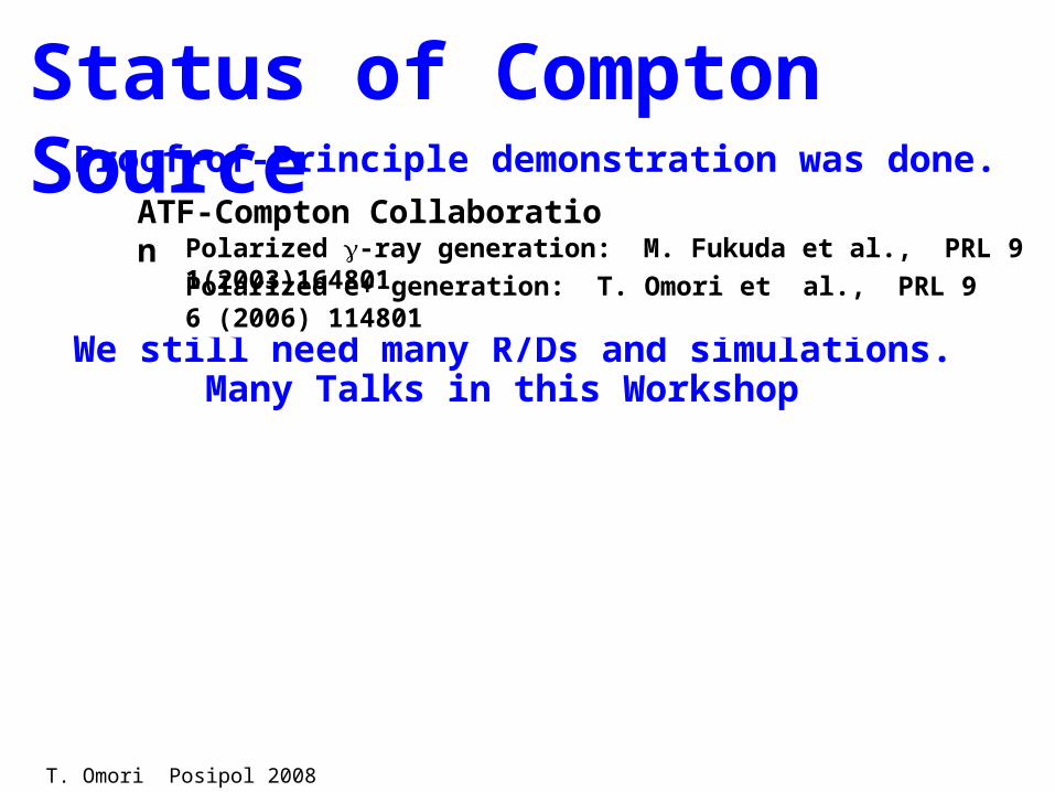
Status of Compton SourceProof-of-Principle demonstration was done.
ATF-Compton Collaboration
Polarized e+ generation: T. Omori et al., PRL 96 (2006) 114801
Polarized -ray generation: M. Fukuda et al., PRL 91(2003)164801
T. Omori Posipol 2008
Status of Compton Source
We still need many R/Ds and simulations. Many Talks in this Workshop
Proof-of-Principle demonstration was done.
ATF-Compton Collaboration
Polarized e+ generation: T. Omori et al., PRL 96 (2006) 114801Polarized -ray generation: M. Fukuda et al., PRL 91(2003)164801
T. Omori Posipol 2008

Status of Compton Source
We still need many R/Ds and simulations. Many Talks in this Workshop
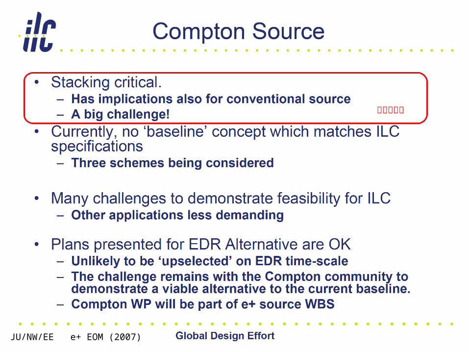
We have 3 schemes. Choice 1 : How to provide e- beam Storage Ring, ERL, Linac Choice 2 : How to provide laser beam Wave length (=1m or =10m ) staking cavity or non stacking cavity Choice 3 : e+ stacking in DR or Not
Proof-of-Principle demonstration was done.ATF-Compton Collaboration
Polarized e+ generation: T. Omori et al., PRL 96 (2006) 114801Polarized -ray generation: M. Fukuda et al., PRL 91(2003)164801
T. Omori Posipol 2008
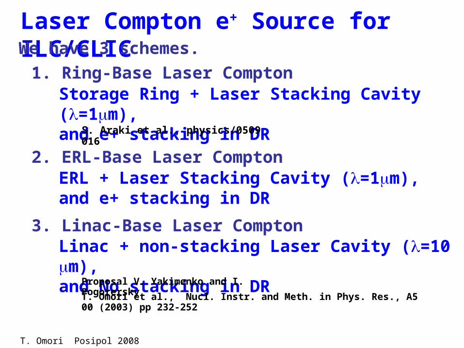
Laser Compton e+ Source for ILC/CLIC
1. Ring-Base Laser Compton
2. ERL-Base Laser Compton
3. Linac-Base Laser Compton
Storage Ring + Laser Stacking Cavity (=1m),and e+ stacking in DR
ERL + Laser Stacking Cavity (=1m),and e+ stacking in DR
Linac + non-stacking Laser Cavity (=10m),and No stacking in DR
We have 3 schemes.
T. Omori et al., Nucl. Instr. and Meth. in Phys. Res., A500 (2003) pp 232-252
Proposal V. Yakimenko and I. Pogorersky
S. Araki et al., physics/0509016
T. Omori Posipol 2008

Laser Compton e+ Source for ILC/CLIC
1. Ring-Base Laser Compton
2. ERL-Base Laser Compton
3. Linac-Base Laser Compton
Storage Ring + Laser Stacking Cavity (=1m),and e+ stacking in DR
ERL + Laser Stacking Cavity (=1m),and e+ stacking in DR
Linac + non-stacking Laser Cavity (=10m),and No stacking in DR
We have 3 schemes.
Good! But we have to choose!T. Omori et al., Nucl. Instr. and Meth. in Phys. Res., A500 (2003) pp 232-252
Proposal V. Yakimenko and I. Pogorersky
S. Araki et al., physics/0509016
T. Omori Posipol 2008
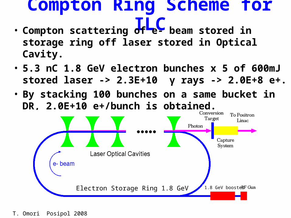
Compton Ring Scheme for ILC• Compton scattering of e- beam stored in storage
ring off laser stored in Optical Cavity.• 5.3 nC 1.8 GeV electron bunches x 5 of 600mJ
stored laser -> 2.3E+10 γ rays -> 2.0E+8 e+.• By stacking 100 bunches on a same bucket in
DR, 2.0E+10 e+/bunch is obtained.
Electron Storage Ring 1.8 GeV 1.8 GeV booster
Parameter Set is Just an Example
Will be changed by the feedback from R/Ds.
T. Omori Posipol 2008

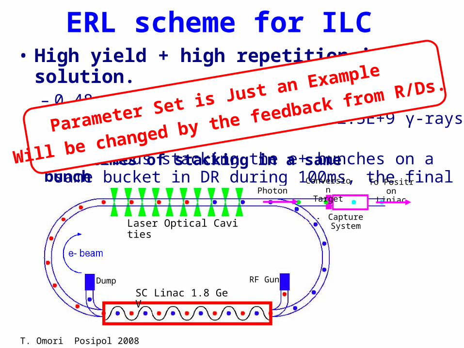
ERL scheme for ILC• High yield + high repetition in ERL solution.
– 0.48 nC 1.8 GeV bunches x 5 of 600 mJ laser, repeated by 54 MHz -> 2.5E+9 γ-rays -> 2E+7 e+.
– Continuous stacking the e+ bunches on a same bucket in DR during 100ms, the final intensity is 2E+10 e+.
SC Linac 1.8 GeV
Laser Optical Cavities
PhotonConversionTarget
CaptureSystem
To PositronLiniac
RF GunDump
1000 times of stacking in a same bunch
T. Omori Posipol 2008
ERL scheme for ILC• High yield + high repetition in ERL solution.
– 0.48 nC 1.8 GeV bunches x 5 of 600 mJ laser, repeated by 54 MHz -> 2.5E+9 γ-rays -> 2E+7 e+.
– Continuous stacking the e+ bunches on a same bucket in DR during 100ms, the final intensity is 2E+10 e+.
SC Linac 1.8 GeV
Laser Optical Cavities
PhotonConversionTarget
CaptureSystem
To PositronLiniac
RF GunDump
1000 times of stacking in a same bunch
Parameter Set is Just an Example
Will be changed by the feedback from R/Ds.
T. Omori Posipol 2008

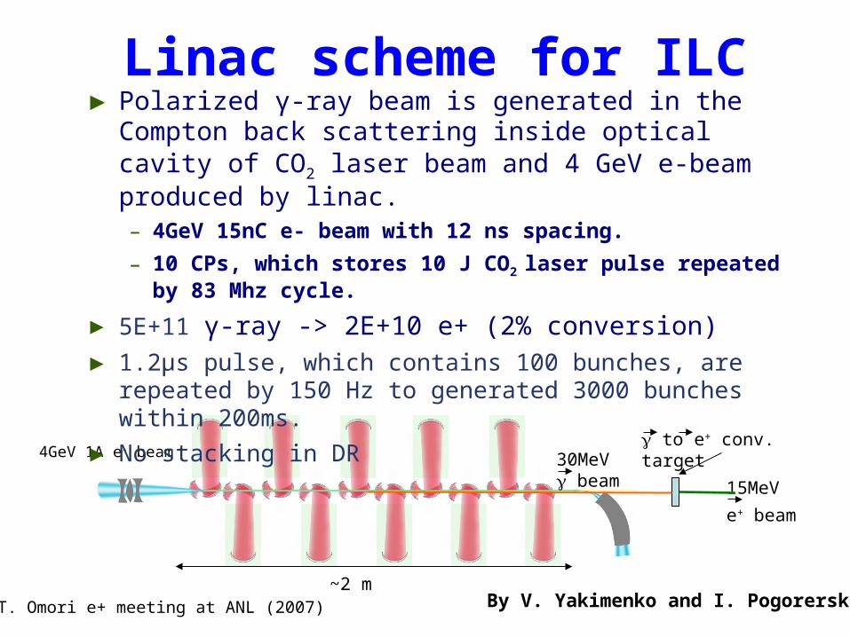
4GeV 1A e- beam 30MeV beam 15MeV
e+ beam
to e+ conv. target
~2 m
► Polarized γ-ray beam is generated in the Compton back scattering inside optical cavity of CO2 laser beam and 4 GeV e-beam produced by linac. – 4GeV 15nC e- beam with 12 ns spacing.
– 10 CPs, which stores 10 J CO2 laser pulse repeated by 83 Mhz cycle.
► 5E+11 γ-ray -> 2E+10 e+ (2% conversion) ► 1.2μs pulse, which contains 100 bunches, are repeated
by 150 Hz to generated 3000 bunches within 200ms.
► No stacking in DR
By V. Yakimenko and I. PogorerskyT. Omori e+ meeting at ANL (2007)
Linac scheme for ILC
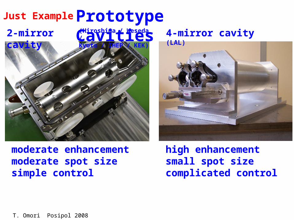
Prototype Cavities4-mirror cavity (LAL)2-mirror cavity
high enhancementsmall spot sizecomplicated control
moderate enhancementmoderate spot sizesimple control
(Hiroshima / Weseda / Kyoto / IHEP / KEK)
Just Example
T. Omori Posipol 2008

Prototype Cavities4-mirror cavity (LAL)2-mirror cavity
high enhancementsmall spot sizecomplicated control
moderate enhancementmoderate spot sizesimple control
(Hiroshima / Weseda / Kyoto / IHEP / KEK)
ATF にてガンマ線生成の実験中
Just Example
T. Omori Posipol 2008
JU/NW/EE e+ EOM (2007)
四角は大森

various scenarios
Compton sources Compton ring – CR (“pulsed”), or Compton ERL – CERL (“continuous”)
accumulation rings ILC damping ring CLIC pre-damping ring
F. Zimmermann Posipol 2008

(1) ILC-CR
F. Zimmermann Posipol 2008

cycle 1, after 1st injection cycle 1, after 5th injection cycle 1, after 10th injection
cycle 1, after 30th injection cycle 2, before 1st injection cycle 2, after 1st injection
cycle 2, after 5th injection cycle 2, after 30th injection cycle 3, before 1st injection
simulation for ILC-CR
F. Zimmermann Posipol 2008
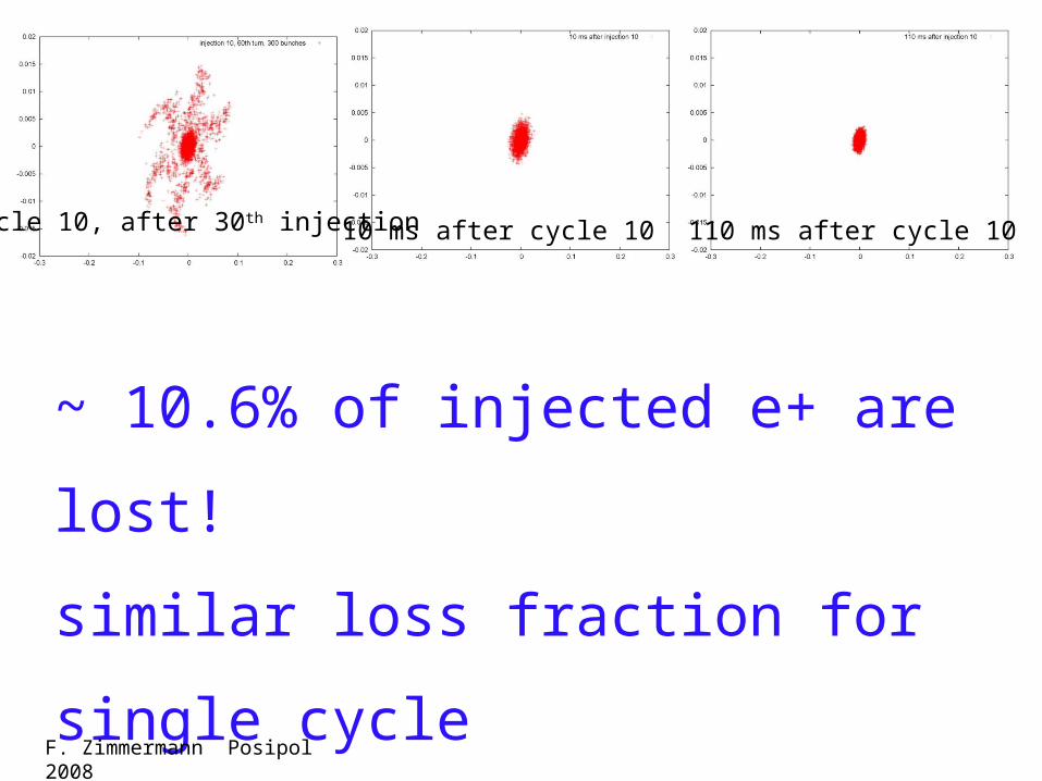
cycle 10, after 30th injection 10 ms after cycle 10 110 ms after cycle 10
~ 10.6% of injected e+ are lost!
similar loss fraction for single cycle
→ stacking efficiency ~90%
for ILC DR Compton version F. Zimmermann Posipol 2008

(2) ILC-CERL
F. Zimmermann Posipol 2008
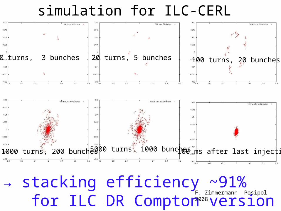
10 turns, 3 bunches 20 turns, 5 bunches 100 turns, 20 bunches
1000 turns, 200 bunches 5000 turns, 1000 bunches 100 ms after last injection
simulation for ILC-CERL
→ stacking efficiency ~91% for ILC DR Compton version
F. Zimmermann Posipol 2008

まとめ(というより大森の意見)
TD phase 1 の間に虚心坦懐に見直すべきアンジュレーター
一番もっともらしい (ready-to-construct に近い ) パラーメーターセットを作る。 Low K アンジュレーターも含めて検討するべきか?
全体 コンベンショナルも含めて、一番 ready-to-construct に近い e+ ソースを考える。 アンジュレーター以外の場合は、 1 m sec の間に 3000 bunches を作る必要は無い。 DR も含めて最適解を探るべき。
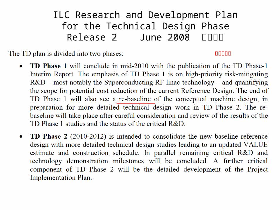
ILC Research and Development Planfor the Technical Design Phase
Release 2 June 2008 より抜粋
赤線は大森


![おもいでばこを 使いこなそう [決定版]「おもいでばこを使いこなそう(決定版)」 6 PASOCOOP おもいでばこを使いこなそう[決定版] 1 “おもいでばこ”とは?](https://img.pdfslide.tips/doc/110x75/5f0647ba7e708231d417335a/-c-oeici.jpg)