Embed Size (px)
Citation preview

NC STATE UNIVERSITY
© M. B. Steer, 1995–2008
M1 L1
1 ECE513 RF Design for Wireless
Professor Michael Steer http://www4.ncsu.edu/~mbs
MODULE 1 RF Systems LECTURE 1 Modulation Techniques Chapter 1, Sections 1.1–1.3
NC STATE UNIVERSITY
© M. B. Steer, 1995–2008
M1 L1
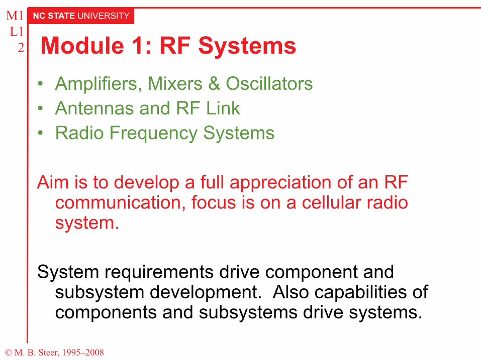
2 Module 1: RF Systems • Amplifiers, Mixers & Oscillators • Antennas and RF Link • Radio Frequency Systems
Aim is to develop a full appreciation of an RF
communication, focus is on a cellular radio system.
System requirements drive component and
subsystem development. Also capabilities of components and subsystems drive systems.
NC STATE UNIVERSITY
© M. B. Steer, 1995–2008
M1 L1
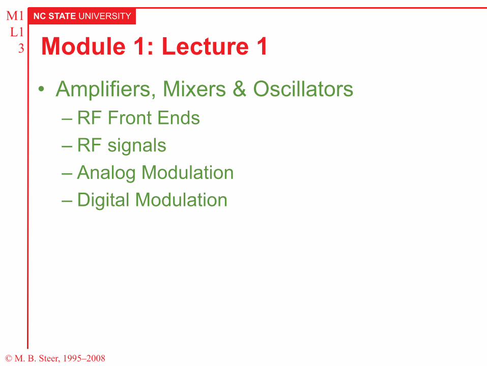
3 Module 1: Lecture 1 • Amplifiers, Mixers & Oscillators
– RF Front Ends – RF signals – Analog Modulation – Digital Modulation
NC STATE UNIVERSITY
© M. B. Steer, 1995–2008
M1 L1
4 Lecture Goal Develop an understanding of modulation techniques used in analog and digital cellular radio.
Lecture Outline • Analog Modulation: AM, FM, PM • Introduction to Digital Modulation: ASK, FSK, PSK • Advanced Modulation Concepts
– Occupied Bandwidth
• Performance of Modulation Types used in Cellular Radio – Analog FM, DQPSK, FSK, GMSK
NC STATE UNIVERSITY
© M. B. Steer, 1995–2008
M1 L1
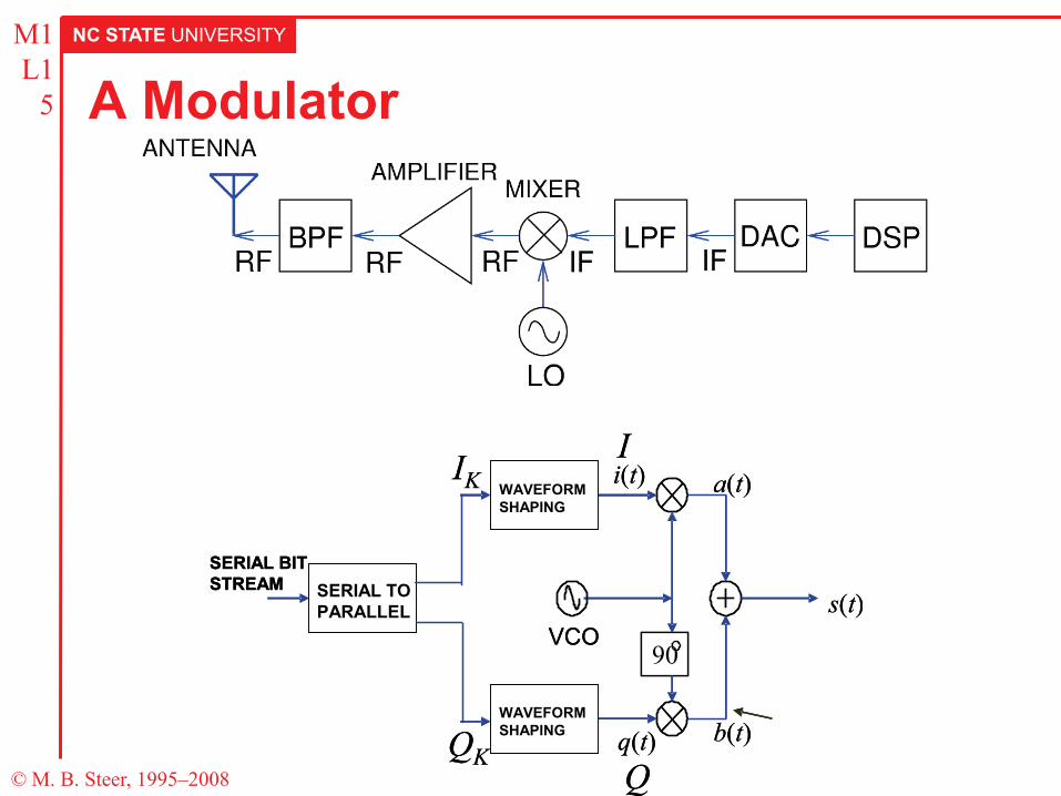
5 A Modulator
90VCO
i(t)
q(t)
a(t)
b(t)
s(t)
WAVEFORMSHAPING
WAVEFORMSHAPING
SERIAL TOPARALLEL
SERIAL BITSTREAM
IK
QK
I
Q
9090VCO
i(t)
q(t)
a(t)
b(t)
s(t)
WAVEFORMSHAPINGWAVEFORMSHAPING
WAVEFORMSHAPINGWAVEFORMSHAPING
SERIAL TOPARALLELSERIAL TOPARALLEL
SERIAL BITSTREAM
IK
QK
I
Q
NC STATE UNIVERSITY
© M. B. Steer, 1995–2008
M1 L1
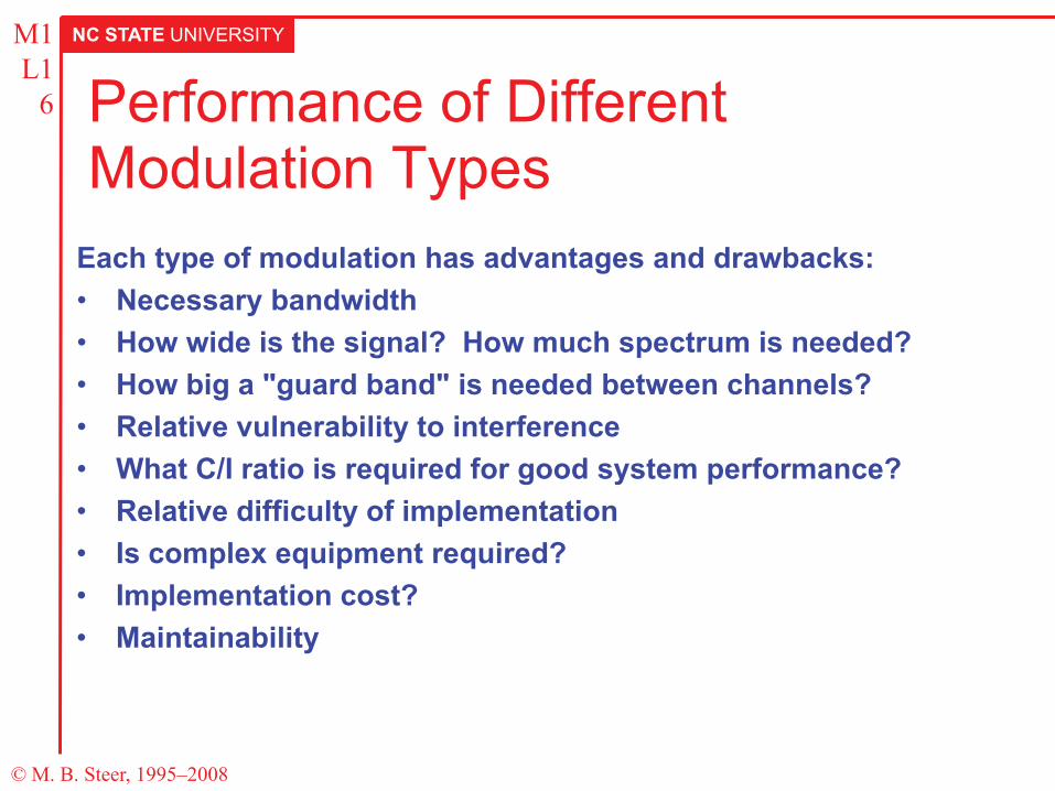
6 Performance of Different Modulation Types
Each type of modulation has advantages and drawbacks: • Necessary bandwidth • How wide is the signal? How much spectrum is needed? • How big a "guard band" is needed between channels? • Relative vulnerability to interference • What C/I ratio is required for good system performance? • Relative difficulty of implementation • Is complex equipment required? • Implementation cost? • Maintainability
NC STATE UNIVERSITY
© M. B. Steer, 1995–2008
M1 L1
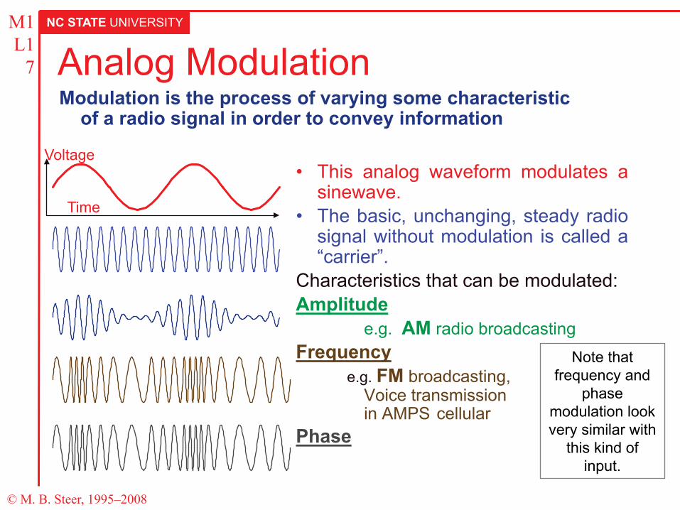
7 Analog Modulation
• This analog waveform modulates a sinewave.
• The basic, unchanging, steady radio signal without modulation is called a “carrier”.
Characteristics that can be modulated: Amplitude e.g. AM radio broadcasting Frequency
e.g. FM broadcasting, Voice transmission in AMPS cellular
Phase
Modulation is the process of varying some characteristic of a radio signal in order to convey information
Voltage
Time
Note that frequency and
phase modulation look very similar with
this kind of input.
NC STATE UNIVERSITY
© M. B. Steer, 1995–2008
M1 L1
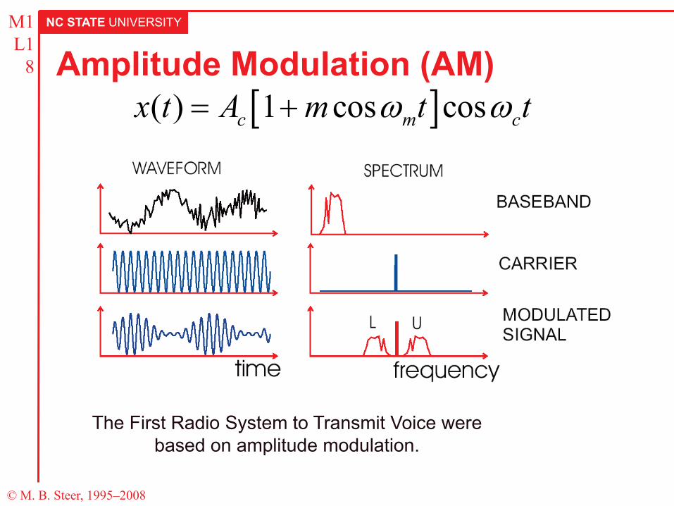
8 Amplitude Modulation (AM)
The First Radio System to Transmit Voice were based on amplitude modulation.
[ ]( ) 1 cos cosc m cx t A m t tω ω= +
NC STATE UNIVERSITY
© M. B. Steer, 1995–2008
M1 L1
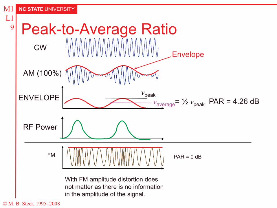
9 Peak-to-Average Ratio CW
AM (100%)
Envelope
vpeak vaverage= ½ vpeak PAR = 4.26 dB ENVELOPE
RF Power
FM
With FM amplitude distortion does not matter as there is no information in the amplitude of the signal.
PAR = 0 dB
NC STATE UNIVERSITY
© M. B. Steer, 1995–2008
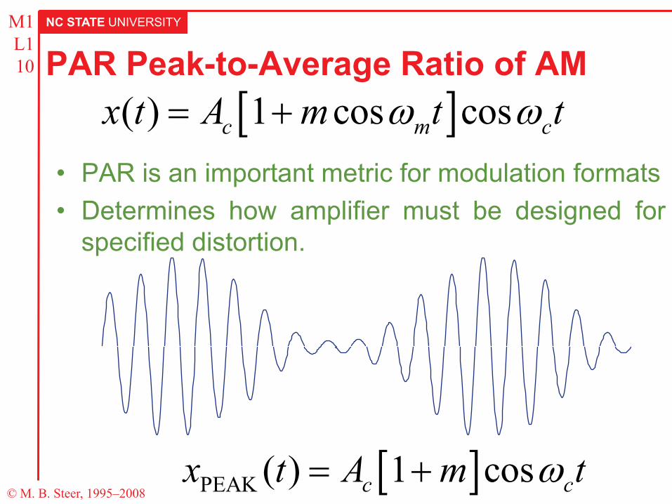
M1 L1 10 PAR Peak-to-Average Ratio of AM
• PAR is an important metric for modulation formats • Determines how amplifier must be designed for
specified distortion.
[ ]( ) 1 cos cosc m cx t A m t tω ω= +
[ ]PEAK ( ) 1 cosc cx t A m tω= +
NC STATE UNIVERSITY
© M. B. Steer, 1995–2008
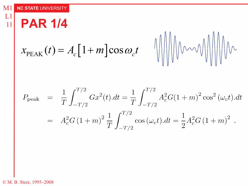
M1 L1 11 PAR 1/4
[ ]PEAK ( ) 1 cosc cx t A m tω= +
NC STATE UNIVERSITY
© M. B. Steer, 1995–2008
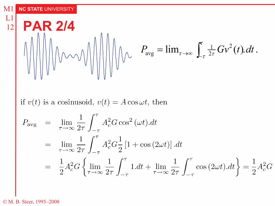
M1 L1 12 PAR 2/4
21avg 2lim ( )P Gv t dt
τ
τ ττ→∞ −= . .∫
NC STATE UNIVERSITY
© M. B. Steer, 1995–2008
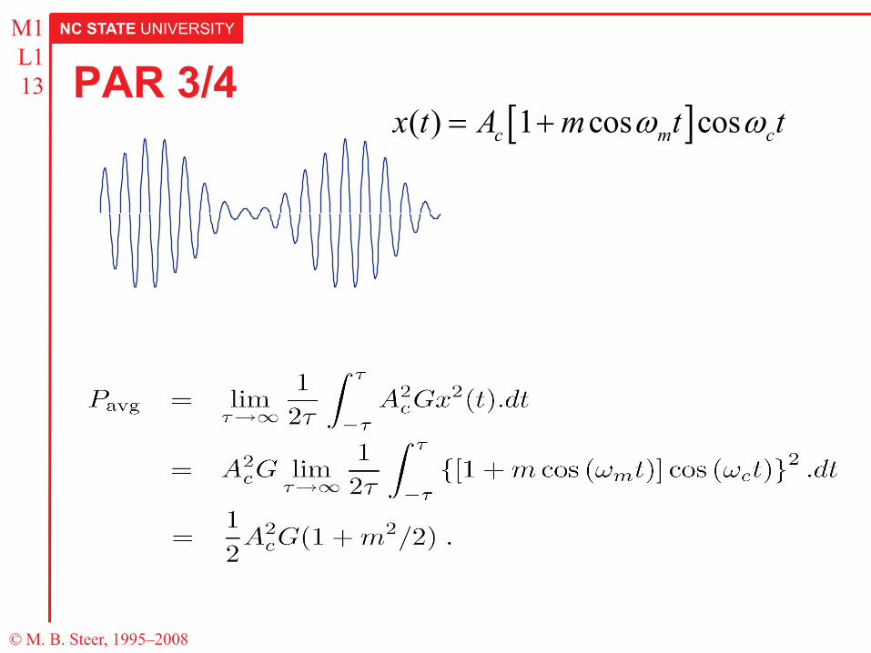
M1 L1 13 PAR 3/4
[ ]( ) 1 cos cosc m cx t A m t tω ω= +
NC STATE UNIVERSITY
© M. B. Steer, 1995–2008
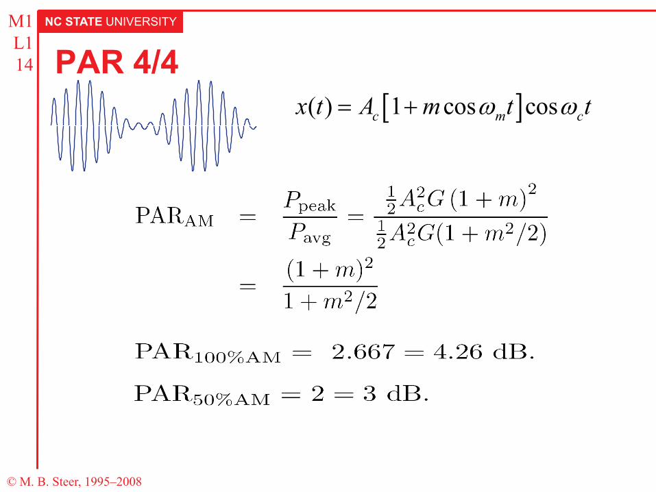
M1 L1 14 PAR 4/4
[ ]( ) 1 cos cosc m cx t A m t tω ω= +
NC STATE UNIVERSITY
© M. B. Steer, 1995–2008
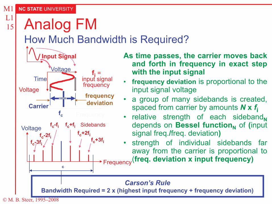
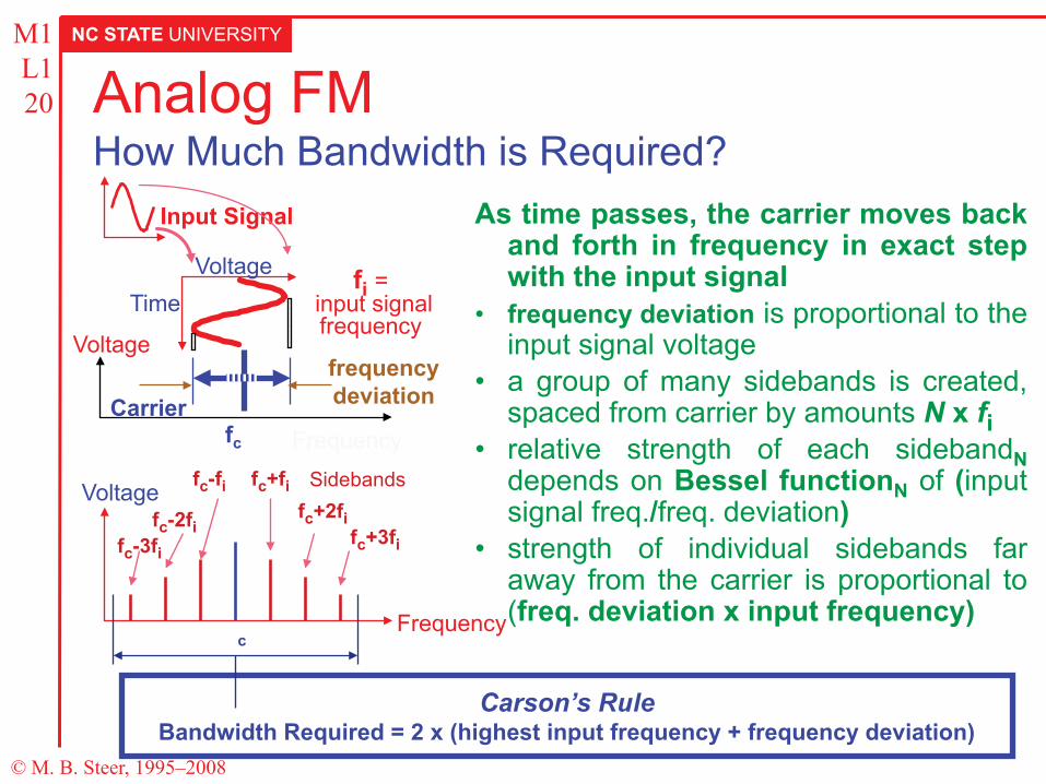
M1 L1 15 Analog FM
How Much Bandwidth is Required?
Carson’s Rule Bandwidth Required = 2 x (highest input frequency + frequency deviation)
As time passes, the carrier moves back and forth in frequency in exact step with the input signal
• frequency deviation is proportional to the input signal voltage
• a group of many sidebands is created, spaced from carrier by amounts N x fi
• relative strength of each sidebandN depends on Bessel functionN of (input signal freq./freq. deviation)
• strength of individual sidebands far away from the carrier is proportional to (freq. deviation x input frequency)
Voltage
Frequency c
Sidebands fc+fi fc+2fi
fc+3fi fc-3fi
fc-fi
fc-2fi
Voltage
Input Signal
fc
frequency deviation
Voltage Time
Carrier Frequency
fi = input signal frequency
NC STATE UNIVERSITY
© M. B. Steer, 1995–2008
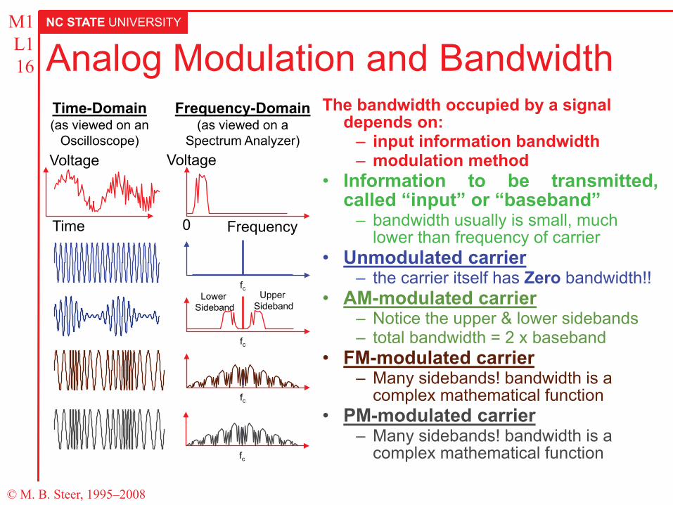
M1 L1 16 Analog Modulation and Bandwidth
The bandwidth occupied by a signal depends on:
– input information bandwidth – modulation method
• Information to be transmitted, called “input” or “baseband”
– bandwidth usually is small, much lower than frequency of carrier
• Unmodulated carrier – the carrier itself has Zero bandwidth!!
• AM-modulated carrier – Notice the upper & lower sidebands – total bandwidth = 2 x baseband
• FM-modulated carrier – Many sidebands! bandwidth is a
complex mathematical function • PM-modulated carrier
– Many sidebands! bandwidth is a complex mathematical function
Voltage
Time
Time-Domain (as viewed on an
Oscilloscope)
Frequency-Domain (as viewed on a
Spectrum Analyzer) Voltage
Frequency 0
fc
fc
Upper Sideband
Lower Sideband
fc
fc
NC STATE UNIVERSITY
© M. B. Steer, 1995–2008
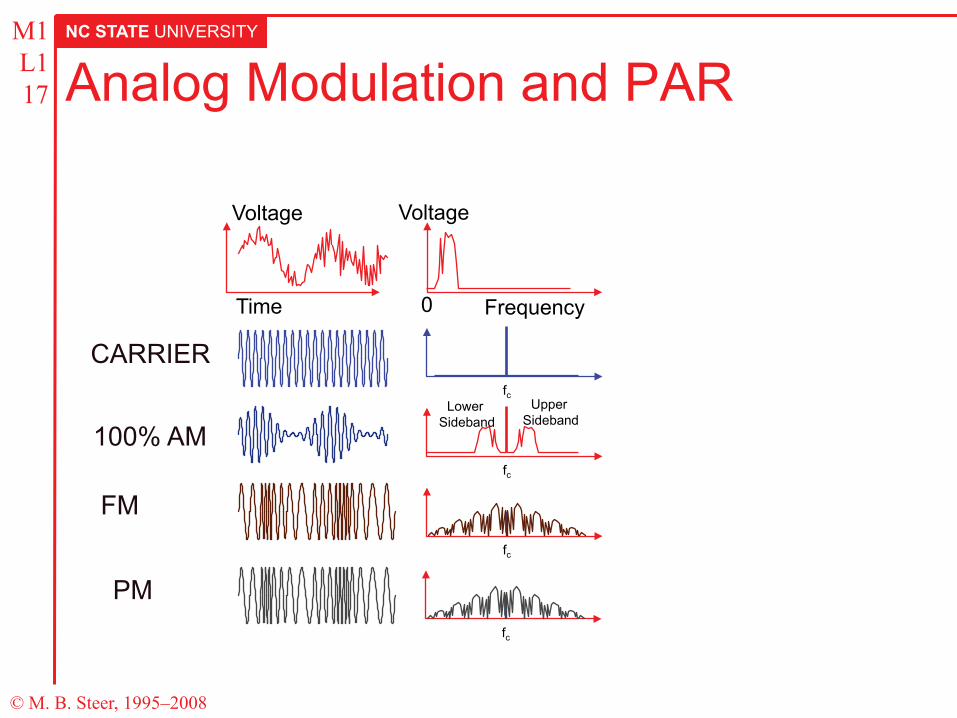
M1 L1 17 Analog Modulation and PAR
Voltage
Time
Voltage
Frequency 0
fc
fc
Upper Sideband
Lower Sideband
fc
fc
CARRIER
100% AM
FM
PM
NC STATE UNIVERSITY
© M. B. Steer, 1995–2008
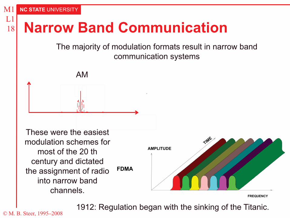
M1 L1 18 Narrow Band Communication
The majority of modulation formats result in narrow band communication systems
AM
FDMA
FREQUENCY
AMPLITUDE
These were the easiest modulation schemes for
most of the 20 th century and dictated
the assignment of radio into narrow band
channels.
1912: Regulation began with the sinking of the Titanic.
NC STATE UNIVERSITY
© M. B. Steer, 1995–2008
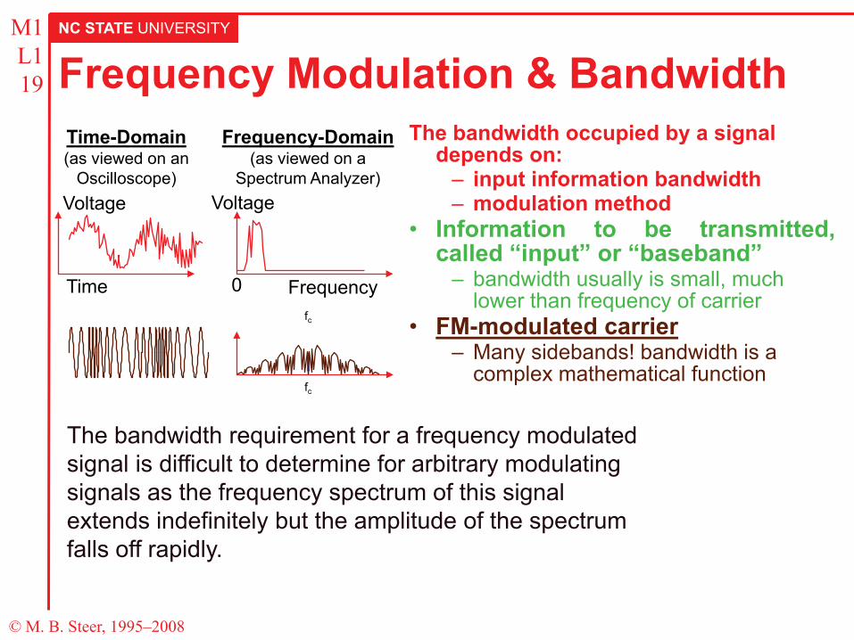
M1 L1 19 Frequency Modulation & Bandwidth
The bandwidth occupied by a signal depends on:
– input information bandwidth – modulation method
• Information to be transmitted, called “input” or “baseband”
– bandwidth usually is small, much lower than frequency of carrier
• FM-modulated carrier – Many sidebands! bandwidth is a
complex mathematical function
Voltage
Time
Time-Domain (as viewed on an
Oscilloscope)
Frequency-Domain (as viewed on a
Spectrum Analyzer) Voltage
Frequency 0 fc
fc
The bandwidth requirement for a frequency modulated signal is difficult to determine for arbitrary modulating signals as the frequency spectrum of this signal extends indefinitely but the amplitude of the spectrum falls off rapidly.
NC STATE UNIVERSITY
© M. B. Steer, 1995–2008
M1 L1 20 Analog FM
How Much Bandwidth is Required?
Carson’s Rule Bandwidth Required = 2 x (highest input frequency + frequency deviation)
As time passes, the carrier moves back and forth in frequency in exact step with the input signal
• frequency deviation is proportional to the input signal voltage
• a group of many sidebands is created, spaced from carrier by amounts N x fi
• relative strength of each sidebandN depends on Bessel functionN of (input signal freq./freq. deviation)
• strength of individual sidebands far away from the carrier is proportional to (freq. deviation x input frequency)
Voltage
Frequency c
Sidebands fc+fi fc+2fi
fc+3fi fc-3fi
fc-fi
fc-2fi
Voltage
Input Signal
fc
frequency deviation
Voltage Time
Carrier Frequency
fi = input signal frequency
NC STATE UNIVERSITY
© M. B. Steer, 1995–2008
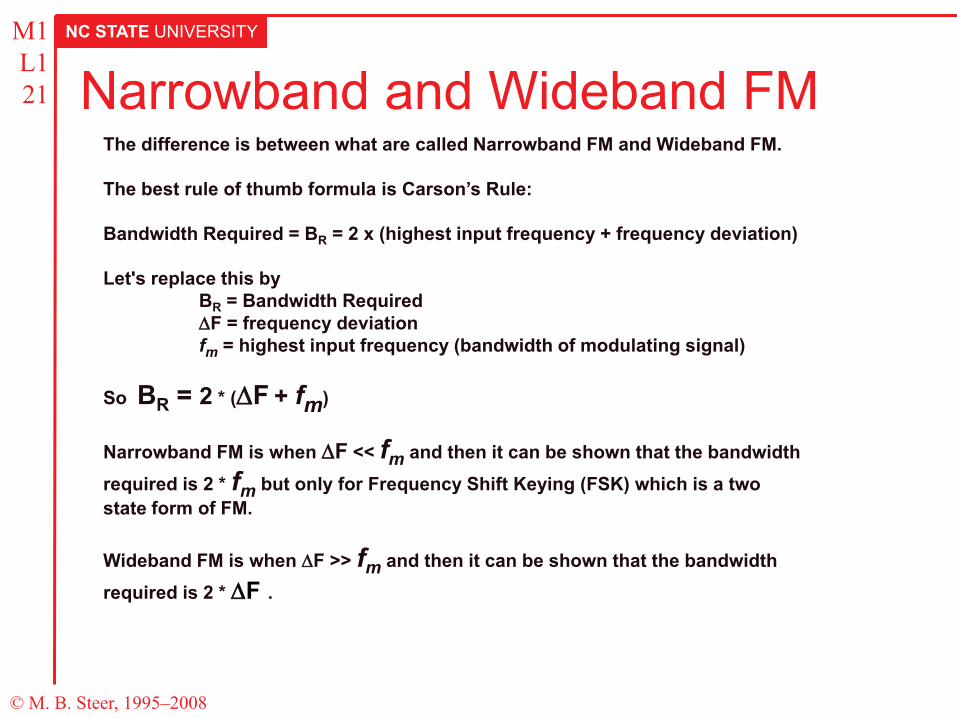
M1 L1 21 Narrowband and Wideband FM
The difference is between what are called Narrowband FM and Wideband FM. The best rule of thumb formula is Carson’s Rule: Bandwidth Required = BR = 2 x (highest input frequency + frequency deviation) Let's replace this by BR = Bandwidth Required ∆F = frequency deviation fm = highest input frequency (bandwidth of modulating signal) So BR = 2 * (∆F + fm) Narrowband FM is when ∆F << fm and then it can be shown that the bandwidth required is 2 * fm but only for Frequency Shift Keying (FSK) which is a two state form of FM. Wideband FM is when ∆F >> fm and then it can be shown that the bandwidth required is 2 * ∆F .

![Atmel AT02865: RF Layout with Microstripww1.microchip.com/downloads/en/AppNotes/Atmel-42131-RF... · 2017-01-05 · Atmel AT02865: RF Layout with Microstrip [APPLICATION NOTE] 42131B−WIRELESS−05/2013](https://img.pdfslide.tips/doc/110x75/5e2528a335871412bd6f1bd7/atmel-at02865-rf-layout-with-2017-01-05-atmel-at02865-rf-layout-with-microstrip.jpg)


![RF Module Design - [Chapter 7] Voltage-Controlled Oscillator](https://img.pdfslide.tips/doc/110x75/55cebbaebb61eb912f8b45f9/rf-module-design-chapter-7-voltage-controlled-oscillator.jpg)
![RF Circuit Design - [Ch1-1] Sinusoidal Steady-state Analysis](https://img.pdfslide.tips/doc/110x75/55d035edbb61ebcd698b4734/rf-circuit-design-ch1-1-sinusoidal-steady-state-analysis.jpg)


![Multiband Transceivers - [Chapter 4] Design Parameters of Wireless Radios](https://img.pdfslide.tips/doc/110x75/55cebbd7bb61eb8c2f8b4620/multiband-transceivers-chapter-4-design-parameters-of-wireless-radios.jpg)
![RF Module Design - [Chapter 2] Noises](https://img.pdfslide.tips/doc/110x75/55cebb8bbb61eb9d2f8b45de/rf-module-design-chapter-2-noises.jpg)


![RF Module Design - [Chapter 3] Linearity](https://img.pdfslide.tips/doc/110x75/55cebc38bb61eb872f8b467d/rf-module-design-chapter-3-linearity.jpg)
![RF Circuit Design - [Ch3-1] Microwave Network](https://img.pdfslide.tips/doc/110x75/55d03525bb61ebc6768b45ac/rf-circuit-design-ch3-1-microwave-network.jpg)
![RF Module Design - [Chapter 8] Phase-Locked Loops](https://img.pdfslide.tips/doc/110x75/55cebb77bb61eba32f8b45bd/rf-module-design-chapter-8-phase-locked-loops.jpg)
![RF Module Design - [Chapter 4] Transceiver Architecture](https://img.pdfslide.tips/doc/110x75/55ca514abb61eb59138b45c0/rf-module-design-chapter-4-transceiver-architecture.jpg)
![RF Module Design - [Chapter 5] Low Noise Amplifier](https://img.pdfslide.tips/doc/110x75/55c6d4bcbb61ebf2428b46cc/rf-module-design-chapter-5-low-noise-amplifier.jpg)