Embed Size (px)
Citation preview
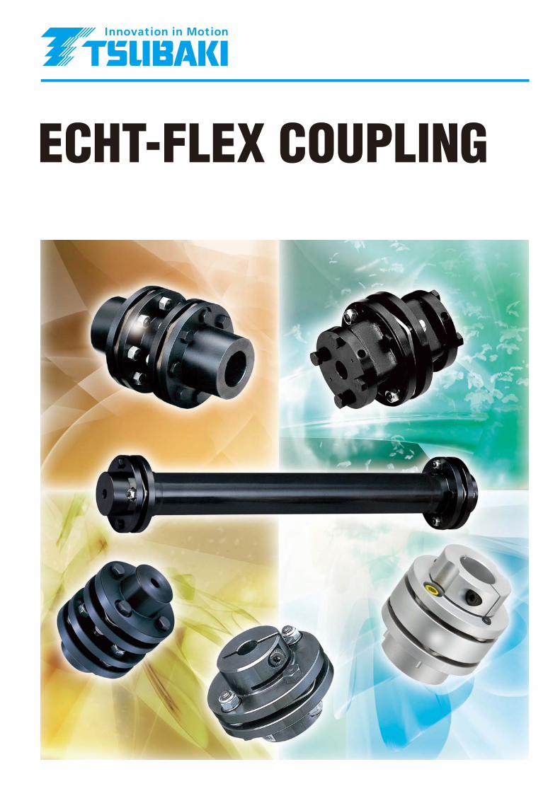
ECHT-FLEX COUPLING


20
EC
HT-
FLE
X
TRANSMISSION CAPACITY / DIMENSIONS NEF-W
Standard Hub×Standard Hub NEF□□W - N□□ X N□□ Extended-Dia. Hub×Standard Hub NEF□□W - K□□ X N□□
① Standard hub ② Reamer bolt ③ Washer A ④ Washer B⑤ Disk ⑥ U-nut ⑦ Spacer ⑧ Set screw
① Standard hub ② Extended-dia. hub ③ Reamer bolt ④ Washer A⑤ Washer B ⑥ Disk ⑦ U-nut ⑧ Spacer ⑨ Set screw
Long Hub×Standard Hub NEF□□W - L□□ X N□□ Extended-Dia. Hub×Extended-Dia. Hub NEF□□W - K□□ X K□□
① Long hub ② Standard hub ③ Reamer bolt ④ Washer A⑤ Washer B ⑥ Disk ⑦ U-nut ⑧ Spacer ⑨ Set screw
① Extended-dia. hub ② Reamer bolt ③ Washer A ④ Washer B⑤ Disk ⑥ U-nut ⑦ Spacer ⑧ Set screw
Extended-Dia. Hub×Long Hub NEF□□W - K□□ X L□□ Long Hub×Long Hub NEF□□W - L□□ X L□□
① Extended-dia. hub ② Long hub ③ Reamer bolt ④ Washer A⑤ Washer B ⑥ Disk ⑦ U-nut ⑧ Spacer ⑨ Set screw
① Long hub ② Reamer bolt ③ Washer A ④ Washer B⑤ Disk ⑥ U-nut ⑦ Spacer ⑧ Set screw
1
NEF02W - N□□ X N□□NEF Series: Spacer Type Couplings The NEF Series Spacer Type coupling incorporates two sets of
disk kits, enabling absorption of all misalignments.
This type of coupling provides the widest application range.
Note: The spacer shape is differentfrom that of other sizes. Thestandard hub and extended-diameter hub are in stock.Contact us for long hubs.

21
NEF-W
Spacer Type Unit: mm
Notes 1. See p. 12 for extended diameter and long hub dimensions. With the long hub, the overall length is extended because dimension “B” is lengthened.
2. All stocked models are manufactured with pilot bores. Models NEF04W through NEF130W have been stocked with shaft bores machined within the above standard stock bore diameter range. (New JIS key, normal type)
3. The maximum rotation speed depends on the transmission capacity of the coupling. No balance adjustment has been conducted.
4. The weight, moment of inertia and GD2 are the values at maximum bore diameter (keyway). For the extended-diameter hub and the long hub, add the individual values listed below.5. Spacer lengths other than the standard length can be manufactured. For details on the Long Spacer Type, see p. 22. 6. The allowable axial displacement is based on the assumption that the angular misalignment is “0”.7. Check the key surface pressure in accordance with your operating conditions (see p. 23). The hub material is S45C.
Increase in Weight, Moment of Inertia and GD2 perExtended-Diameter Hub / Long Hub
Model No.Extended-Dia. Hub Long Hub
Weight kg Moment ofInertia kg・m2
GD2
{kg f・cm2} Weight kg Moment ofInertia kg・m2
GD2
{kg f・cm2}
NEF02W 0.027 0.18×10⁻⁴ { 0.74} - - -
NEF04W 0.046 0.34×10⁻⁴ { 1.35} 0.056 0.12×10⁻⁴ { 0.47}
NEF10W 0.15 1.3 ×10⁻⁴ { 5.18} 0.20 0.77×10⁻⁴ { 3.08}
NEF18W 0.042 1.1 ×10⁻⁴ { 4.19} 0.14 0.67×10⁻⁴ { 2.69}
NEF25W 0.13 3.0 ×10⁻⁴ { 11.3 } 0.20 1.3 ×10⁻⁴ { 5.41}
NEF 45W 0.14 5.8 ×10⁻⁴ { 23.2 } 0.30 2.8 ×10⁻⁴ { 11.2 }
NEF80W 0.16 11 ×10-4 { 42.6 } 0.47 6.4 ×10⁻⁴ { 25.6 }
NEF130W 0.67 36 ×10-4 { 144 } 0.99 20 ×10-4 { 82.1 }
NEF210W 1.09 73 ×10-4 { 289 } 2.45 64 ×10-4 { 254 }
NEF340W 0.90 118 ×10-4 { 473 } 3.85 132 ×10-4 { 533 }
NEF540W 2.31 273 ×10-4 {1089 } 3.91 178 ×10-4 { 710 }
NEF700W 2.91 431 ×10-4 {1724 } 4.41 236 ×10-4 { 929 }
Model No.
AllowableTorque
N・m{kg f・m}
Max.Rotation
Speed
r/min
RoughBore
d
KeywayStandard
Stock BoreDia. Range
Keyway Max. Shaft Dia.φTorsional Stiffness
N・m/rad{kg f・m/rad}
Axial SpringConstant
N/mm{kg f/mm}A1 A2 A3Long
HubExtended-Dia. Hub
NEF700W 6860 {700} 3100 50 - 118 130 29.1 ×10⁵{29.7 ×10⁴} 294 {30 } 337.2 385.6 434
NEF02W 19.6{ 2} 20000 8 14-25 - 25 1.00×10⁴{ 0.10×10⁴} 34.3{ 3.5} 63 - -
NEF04W 39.2{ 4} 20000 8 11-22 23 29 1.18×10⁴{ 0.12×10⁴} 20.6{ 2.1} 86.8 101.4 116
NEF10W 98 { 10} 20000 10 12-30 32 40 3.92×10⁴{ 0.4 ×10⁴} 29.4{ 3 } 89.8 104.4 119
NEF18W 176 { 18} 18000 12 14-35 35 42 7.84×10⁴{ 0.8 ×10⁴} 63.7{ 6.5} 104.4 120.7 137
NEF25W 245 { 25} 15000 15 18-42 42 48 12.7 ×10⁴{ 1.3 ×10⁴} 78.4{ 8 } 120 136.5 153
NEF45W 441 { 45} 13000 15 25-50 50 60 21.6 ×10⁴{ 2.2 ×10⁴} 109 {11.1} 144.2 163.1 182
NEF80W 784 { 80} 12000 15 30-60 60 70 39.2 ×10⁴{ 4.0 ×10⁴} 153 {15.6} 164.6 186.8 209
NEF130W 1270 {130} 10000 25 35-70 74 80 73.5 ×10⁴{ 7.5 ×10⁴} 177 {18.1} 192.4 220.2 248
NEF210W 2060 {210} 8000 25 - 83 90 11.3 ×10⁵{11.5 ×10⁴} 225 {23 } 216 272.5 329
NEF340W 3330 {340} 7500 45 - 95 110 16.2 ×10⁵{16.5 ×10⁴} 235 {24 } 249.4 313.2 377
NEF540W 5290 {540} 3400 50 - 109 120 21.4 ×10⁵{21.8 ×10⁴} 274 {28 } 286.8 337.9 389
PCD
44
49.5
63
71
82
96
111
134
153
172
198
218
StandardHub
20
23
32
35
42
50
60
74
83
95
109
118
*1: Indicate the smaller bore diameter first.*2: Indicate the rough bore (symbol “R”) first.
NEF18W - N30J X K40EModel No.
TypeS: Single TypeW: Spacer Type
Bore Diameter(Rough bore: R)
Reference Number System (Example)
Type of HubN: Standard HubK: Extended-dia. HubL: Long HubB: Square Hub
� See p. 12.
Shaft Coupling MethodJ: Keyway of new JIS
normal typeE: Keyway of old JIS
Type 2C: Clamp (See p. 28)P2: Power-Lock (See p. 31)
� The number indicates the number of power locks.
T: Taper Shaft Bore (See p. 49)
����� ��� B BL K Dd N No Ni T T'
������� � ��� �������� ���
kg
������ �� ����� �
kg m2
GD2
{kg f cm2}� ��
� ����������� ������
NEF700W 101.6 150 276 120 146 164 146 40 -8.4 2 8.0 60 5972 10-4 {23889 }
NEF02W 20 57 21 24 24 11 2 1.6 0.45 1.66 10-4 { 6.64 }
NEF04W 25.4 40 67.5 29 25 33 25 15.5 0.9 2 1.6 1.1 5.3 10-4 { 21.4 }
NEF10W 25.4 40 81 37 37 46 37 16 1.4 2 2.0 1.4 12 10-4 { 47 }
NEF18W 28.7 45 93 39 38 48 38 23 6.7 2 2.4 2.3 25 10-4 { 100 }
NEF25W 33.5 50 104 45 47 58 47 21 4.5 2 2.8 3.0 41 10-4 { 166 }
NEF45W 41.1 60 126 51 58 69 58 23 4.1 2 3.2 6.6 110 10-4 { 440 }
NEF80W 47.8 70 143 61 71 81 71 29.5 7.3 2 3.6 10.3 200 10-4 { 800 }
NEF130W 57.2 85 168 73 92 102 92 20 -7.8 2 5.0 16.1 447 10-4 { 1787 }
NEF210W 63.5 120 194 84 103 114 103 32.5 -24 2 5.4 23.2 931 10-4 { 3722 }
NEF340W 76.2 140 214 97 118 132 118 19.5 -44.3 2 6.6 40.2 1478 10-4 { 5912 }
NEF540W 88.9 140 246 110 135 151 135 24.5 -15.6 2 7.6 55 3014 10-4 {12055 }
E F H HL J
4.9 5.5 32 45 23
6.1 7.5 34 50 36
6.6 7.5 46 66 39
8.3 9 51 66 47
11.2 9 61 78 53
11.7 11.5 71 92 62
11.7 14 84 104 69
16.8 14 106 129 78
17.0 16.5 118 147 89
21.6 16.5 137 166 97
23.9 19 156 191 109
27.2 25.5 169 209 134
mm
��������� ��� ������
deg
�� ���� ��� ������
1.8
0.3
0.5
0.55
0.6
0.7
0.8
0.9
1.0
1.2
1.3
1.4
TRANSMISSION CAPACITY / DIMENSIONS

22
EC
HT-
FLE
X
TRANSMISSION CAPACITY / DIMENSIONS NEF-W
Long Spacer Type The NEF Series Long Spacer Type of coupling enables the use of a floating shaft when there is some distance between devices. Depending on the
spacer length, the Long Spacer Type of coupling can also absorb a large amount of eccentricity. This coupling is suitable for line shaft drives to miter
gearboxes.
Formula for Torsional StiffnessCalculation of Vertical Long Spacer TypeUse the following formula to calculate the torsional
stiffness of vertical Long Spacer Type coupling.
Approx. Weight of Long Spacer Type Coupling / Moment ofInertia and GD2 Calculation Formulae
Torsional Stiffness Calculation for Vertical Long Spacer Type If dimension “J” for each coupling size exceeds the value listed in the following table when a
Long Spacer Type is installed vertically, a thrust supporter is required as shown on the right.
T×104
(J-J1)・K1+K2
N・m/rad{kgf・m/rad}Unit:
J : The dimension “J” given in the external drawing (distance between
hub end faces) in mm.
T: The allowable torque given in the transmission capacity table
in N・m{kgf・m}Substitute the constants given in the above table for J1, K1 and K2.
Use the following formula to calculate theweight of the Long Spacer Type (atmaximum bore diameter).
Unit: kg
Weight=W1(J-J1)+W2
J : Dimension “J” (distance between hub end faces) in
mm.
Substitute the constants given in the above table for J1,
W1, W2, d1, d2, G1 and G2.
Use the following formulae to calculate themoment of inertia and GD2 (at maximumbore diameter).
GD2=W1×d1(J-J1)+G1
Unit: kgf・cm2
Moment of inertia=W1×d2(J-J1)+G2
Unit: kg・cm2
* This formula applies to cases where dimension “J” exceeds “J1” (Unit: cm).
N3
N2
N1
Model No. J1 K1 K2
NEF04W 63 0.0949 32.0
NEF10W 64 0.0857 22.2
NEF18W 74 0.1152 22.5
NEF25W 89.4 0.0856 19.2
NEF45W 105.6 0.0656 20.0
NEF80W 119 0.0579 20.0
NEF130W 148 0.0436 17.3
NEF210W 161 0.0413 18.3
NEF340W 195.6 0.0434 20.6
NEF540W 225.6 0.0276 49.5
NEF700W 257.6 0.0286 47.1
NEH09W 258 0.0360 17.0
NEH14W 292 0.0560 16.3
NEH20W 330 0.0374 15.4
NEH30W 373 0.0374 14.3
NEH41W 390 0.0354 15.8
Weight Moment of Inertia, GD2
Model No. W1 W2 J1 G1 d1 G2 d2
NEF04W 0.02 1.2 6.3 23 8.8 6 2.19
NEF10W 0.03 1.5 6.4 48 15.3 12 3.83
NEF18W 0.03 2.7 7.4 105 18.6 26 4.65
NEF25W 0.04 3.5 8.9 173 28.2 43 7.05
NEF45W 0.06 6.3 10.6 459 41.1 115 10.28
NEF80W 0.09 9.6 11.9 936 56.5 234 14.13
NEF130W 0.12 15.4 14.8 1948 94.3 487 23.59
NEF340W 0.19 29.9 19.6 6475 159.1 1619 39.78
NEF540W 0.36 46.1 22.6 13185 208.4 3246 52.09
NEF700W 0.38 69.5 25.8 25423 241.9 6356 60.47
NEH09W 0.44 64.1 25.8 22311 217.5 5578 54.38
NEH14W 0.44 72.4
110.7
150.9
197.9
29.2 25117 217.5 6279 54.38
NEH20W 0.65 33 49157 311.0 12289 77.74
NEH30W 0.75 37.3 85693 407.5
461.2
21423 101.87
NEH41W 0.95 39 132760 33190 115.3
NEF210W 0.16 22.5 16.1 4006 119.2 1001 29.79
Unit: mm
Model No.
NEH14W 1767
NEH20W 1277
NEH30W 1747
NEH41W 1355
Model No. Model No. Dimension “J” Dimension “J”
NEF04W NEF130W 1910
NEF10W NEF210W 1924
NEF18W NEF340W 2143
NEF25W NEF540W 1542
NEF45W NEF700W 1463
NEF80W NEH09W 1153
Dimension “J”
319
408
1171
1429
1386
1505
�������� �� ������ ����
Thrust supporter
461.2

23
NEF-W
Notes 1. All sizes are custom-made. 2. When placing an order, specify dimension “J”. Consult with us if your required dimension is 6000 mm or greater. 3. When the Long Spacer Type is used at a high rotation speed, or if dimension “J” is extremely long, balance adjustment or a critical speed check may be required. See p. 9. 4. Contact us to vertically install a Long Spacer Type coupling. 5. The NEF10W, 18W and 25W Power-Lock Type couplings use the square hub for power lock. (See p. 12)6. Refer to the following description and check the key surface pressure in accordance with your operating conditions. The hub material is S45C.
Installation (Example) Reference Number System (Example)
Roller table
Roller Roller
Pillow block
ECHT-FLEX coupling
ECHT-FLEX coupling
Miter gearboxMitergearbox
Unit: mm
Model No.Type
(Numberof Bolts)
Allowable Torque
N・m{kg f・m}
RoughBore
d
Max.Bore Dia.(Keyway)
B Dd E H N3 A J
Allowable Misalignment
AngularMisalignmentθ(deg)
AxialDisplacement
ParallelMisalignmentε
NEF 04W 4 39.2{ 4} 8 23 25.4 29 6.1 34 32
2B+J
2 ±1.6
NEF 10W 4 98 { 10} 10 32 25.4 37 6.6 46 42 2 ±2.0
NEF 18W 4 176 { 18} 12 35 28.7 39 8.3 51 46 2 ±2.4
NEF 25W 4 245 { 25} 15 42 33.5 45 11.2 61 56 2 ±2.8
NEF 45W 4 441 { 45} 15 50 41.1 51 11.7 71 68 2 ±3.2
NEF 80W 4 784 { 80} 15 60 47.8 61 11.7 84 80 2 ±3.6
NEF130W 4 1270 { 130} 25 74 57.2 73 16.8 106 102 2 ±5.0
NEF210W 4 2060 { 210} 25 83 63.5 84 17 118 115 2 ±5.4
NEF340W 4 3330 { 340} 45 95 76.2 97 21.6 137 132 2 ±6.6
NEF540W 4 5290 { 540} 50 109 88.9 110 23.9 156 154 2 ±7.6
NEF700W 4 6860 { 700} 70 118 101.6 120 27.2 169 165.2 2 ±8.0
NEH 09W 6 8820 { 900} 70 111 110 144 19 161 159 1.4 ±3.2
NEH 14W 8 13700 { 1400} 70 111 127 155 19 161 159 1 ±2.1
NEH 20W 8 19600 { 2000} 75 133 146 178 19 193 190.7 1 ±2.4
NEH 30W 8 29400 { 3000} 75 152 165 201 21.5 218 216.3 1 ±2.8
NEH 41W 8 40200 { 4100} 120 165 171 218 24 240 232 1 ±2.8
NEH 55W 8 53900 { 5500} 130 187 225 252 29.5 272 267.4 1 ±3.6
NEH 70W 8 68600 { 7000} 150 205 247 275 31.3 297 280 1 ±3.8
NEH 90W 8 88200 { 9000} 150 231 278 304 32.0 334 323.9 1 ±4.3
NEH110W 8 108000 {11000} 190 254 305 343 32.5 364 355.6 1 ±4.8
NEH135W 8 132000 {13500} 190 263 317 350 34.0 382 381 1 ±5.0
NEH150W 8 147000 {15000} 210 275 331 368 34.5 399 381 1 ±5.6
NEH180W 8 176400 {18000} 210 289 347 380 35.5 419 406.4 1 ±5.7
K N2
67.5 27
81 36
93 40
104 50
126 60
143 70
168 92
194 103
214 120
246 134
276 145.2
276 135
276 135
308 160.7
346 186.3
375 196
445 227.4
470 230
511 273.9
556 305.6
587 331
629 331
654 344.6
N1
17
26
30
38
48
61
76
88
106
125
136
127
127
150
175
187
207
209
247
277
304
304
319
(J-
E )×
sin
1 - 2θReq
uir
ed l
ength
(Max
6000
)R
equir
ed l
ength
(Max
4000
)
*1: Indicate the smaller bore diameter first.*2: Indicate the rough bore (symbol “R”) first.
*[Reference] Key Surface Pressure Calculation
P= 2000×T(N/mm2)D×t×B
(T = Operating torque (N·m), D = Bore diameter (mm), t = Key height (mm), B = Effective key length (mm))D
B
t
NEF25W - N35JV X N40E - J1000Model No.
Spacer Type
Bore Diameter(Rough bore: R)
Dimension “J”
Type of HubN: Standard HubK: Extended-Dia. HubL: Long HubB: Square Hub
� See p. 12.
Indicates the lower-side bore diameter of the vertical Long Spacer Type coupling.
Shaft Coupling MethodJ: Keyway of new JIS normal typeE: Keyway of old JIS Type 2C: Clamp (See p. 28)P2: Power-Lock (See p. 31)T: Taper Shaft Bore (See p. 49)
J: Long SpacerJS: Long Spacer (standard
length) (See p. 24)JT: Single Plate Spacer
(See p. 25)
TRANSMISSION CAPACITY / DIMENSIONS

24
EC
HT-
FLE
X
TRANSMISSION CAPACITY / DIMENSIONS NEF-W
Long Spacer Type Couplings in StockLong spacers with specific dimensions are always in stock and available for quick delivery.JS Type is designed with balance equivalent to G6.3/1800r/min.
N
FNo
T
N3
N2
N1
J Type JS Type
φDoφPCD
NEF04WNEF10WNEF18WNEF25WNEF45WNEF80WNEF130WNEF210WNEF340W
100
○○○○
127
○○○○
140
○○○○○○○
180
○○○○○
200●●●●○○○○○
250●●●●○○○
300●●●●
350●●●●
400●●●●
450●●●●
500●●●●
600●●●●
700●●●●
800●●●●
900●●●●
1000●●●●
○:JS Type ●:J Type
200,250,300,350,400,450,500,600,700,800,900,1000
100,140200,250,300,350,400,450,500,600,700,800,900,1000
100,140200,250,300,350,400,450,500,600,700,800,900,1000
100,127,140200,250,300,350,400,450,500,600,700,800,900,1000100,127,140,180,
200,250127,140,180,200,
250127,140,180,200,
250
140,180,200
180,200
-
37
-
38
-
47
-
58
71
92
103
118
-
46
-
48
-
58
-
69
81
102
114
132
17
-
26
-
30
-
38
-
-
-
-
-
27
-
36
-
40
-
50
-
-
-
-
-
32
-
42
-
46
-
56
-
-
-
-
-
J
JS
J
JS
J
JS
J
JS
JS
JS
JS
JS
8
10
12
15
15
15
25
25
45
23
32
35
42
50
60
74
83
95
25.4
25.4
28.7
33.5
41.1
47.8
57.2
63.5
76.2
6.1
6.6
8.3
11.2
11.7
11.7
16.8
17
21.6
15.5
16
23
21
23
29.5
20
32.5
19.5
67.5
81
93
104
126
143
168
194
214
49.5
63
71
82
96
111
134
153
172
7.5
7.5
9
9
11.5
14
14
16.5
16.5
29
37
39
45
51
61
73
84
97
34
46
51
61
71
84
106
118
137
2B+J
NEF04W
NEF10W
NEF18W
NEF25W
NEF45W
NEF80W
NEF130W
NEF210W
NEF340W
dJ BA DD E F H K N 0 NN 1 N2 N3 T PCD
Model No.“J”: Distance between Hub End Faces
List of Models in Stock
Constant Size Long Spacer Type
Table of Dimensions
Model No. TypeLowerBore
Max. Shaft BoreDiameter
(Keyway)

25
NEF-W
Using the Long Spacer Type Couplings in Stock The following methods are available if the Long Spacer Type couplings in stock do not fit your equipment interface.
①When the required Long Spacer is slightly longer than theproduct in stock...
hUse the long hub on both sides.
②When the required long spacer is slightly shorter than theproduct in stock...
hExtend both shafts from the hubs.The disk’s bore diameter can be made to fit the maximum shaftdiameter of either the standard or the long hub.
Single Plate Spacer Type The NEF Series Single Plate Spacer Type reduces the distance between hub end faces (dimension “J”) and is suitable for applications where the
distance between shaft ends is short, or where the overall length must be shortened.
PCD
B BJ
E E
KdH
A T
NEF04WNEF10WNEF18WNEF25WNEF45WNEF80W
NEF130WNEF210WNEF340WNEF540WNEF700W
����� ��� ������� �����N·m{kgf·m} 39.2 { 4} 98 { 10} 176 { 18} 245 { 25} 441 { 45} 784 { 80}1270 {130}2060 {210}3330 {340}5290 {540}6860 {700}
����� ���� d 810121515152525455050
���� ���� ���� �������
23 32 35 42 50 60 74 83 95109118
PCD 49.5 63 71 82 96111134153172198218
A 79 79.6 94.3107.2128.5148.9174197.5228.8265.8309.2
B25.425.428.733.541.147.857.263.576.288.9
101.6
E 6.1 6.6 8.311.211.711.716.81721.623.927.2
H344651617184
106118137156169
J 28.2 28.8 36.9 40.2 46.3 53.3 59.6 70.5 76.4 88106
K 67.5 81 93104126143168194214246276
T15.51623212329.52032.519.524.540
����� mm
Reference Number System (Example)
*1: Indicate the smaller bore diameter first.*2: Indicate the rough bore (symbol “R”) first.
NEF25W - N35J X N40E - JT40.2Model No.
Spacer Type Bore Diameter(Rough bore: R)
Dimension “J”
Type of HubN: Standard HubK: Extended-Dia. HubL: Long HubB: Square Hub
� See p. 12.
Shaft Coupling MethodJ: Keyway of new JIS normal typeE: Keyway of old JIS Type 2C: Clamp (See p. 28)P2: Power-Lock (See p. 31)T: Taper Shaft Bore (See p. 49)
JT : Single Plate Spacer
TRANSMISSION CAPACITY / DIMENSIONS

26
EC
HT-
FLE
X
TRANSMISSION CAPACITY / DIMENSIONS NEF
Standard Hub×Standard Hub NEF□□S - N□□ X N□□
① Standard hub ② Reamer bolt ③ Washer A ④ Washer B⑤ Disk ⑥ U-nut ⑦ Spacer
Extended-Dia. Hub×Standard Hub NEF□□S - K□□ X N□□
① Standard hub ② Extended-dia. hub ③ Reamer bolt ④ Washer A⑤ Washer B ⑥ Disk ⑦ U-nut ⑧ Set screw
Long Hub×Standard Hub NEF□□S - L□□ X N□□
① Long hub ② Standard hub ③ Reamer bolt ④ Washer A⑤ Washer B ⑥ Disk ⑦ U-nut ⑧ Set screw
Extended-Dia. Hub×Extended-Dia. Hub NEF□□S - K□□ X K□□
① Extended-dia. hub ② Reamer bolt ③ Washer A ④ Washer B⑤ Disk ⑥ U-nut ⑦ Set screw
Extended-Dia. Hub×Long Hub NEF□□S - K□□ X L□□
① Extended-dia. hub ② Long hub ③ Reamer bolt ④ Washer A⑤ Washer B ⑥ Disk ⑦ U-nut ⑧ Set screw
Long Hub×Long Hub NEF□□S - L□□ X L□□
① Long hub ② Reamer bolt ③ Washer A ④ Washer B⑤ Disk ⑥ U-nut ⑦ Set screw
NEF Series: Single Type Couplings The NEF Series Single Type employs a single disk set, enabling absorption of angular eccentricity only. This type cannot absorb parallel
misalignment, so it is recommended only for applications that enable precision centering of the servo motor for NC machining centers, NC wood
machining tools, etc.
Under general centering conditions, use of the Spacer Type is recommended.

27
NEF
Notes 1. See p. 12 for extended diameter and long hub dimensions. With the long hub, the overall length is extended because dimension “B” is lengthened.
2. All stocked models are manufactured with pilot bores. Models NEF04W through NEF130W have been stocked with shaft bores machined within the above standard stock bore diameter range. (New JIS key, normal type)
3. The maximum rotation speed depends on the transmission capacity of the coupling. No balance adjustment has been conducted.
4. The weight, moment of inertia and GD2 are the values at maximum bore diameter (keyway). For the extended-diameter hub and the long hub, add the individual values listed below.5. The allowable axial displacement is based on the assumption that the angular misalignment is “0”.6. Check the key surface pressure in accordance with your operating conditions (see p. 23). The hub material is S45C.
Reference Number System (Example)
Single Unit: mm
Model No.
AllowableTorque
N・m{kg f・m}
Max. RotationSpeed
r/min
RoughBore
d
StandardStock BoreDia. Range
Keyway Max. Shaft Dia.φTorsional Stiffness
N・m/rad{kg f・m/rad}
Axial SpringConstant
N/mm{kg f/mm}A1 A2Standard
HubExtended-Dia. Hub
NEF700S 6860{700} 3100 50 - 118 130 58.8 ×10⁵{60 ×104} 588 {60 } 230.4 278.8
NEF02S 19.6{ 2} 20000 8 14~25 20 25 1.96×10⁴{ 0.2 ×10⁴} 68.6{ 7.0} 44.9 -
NEF04S 39.2{ 4} 20000 8 11~22 23 29 2.45×10⁴{ 0.25×10⁴} 40.2{ 4.1} 56.9 71.5
NEF10S 98 { 10} 20000 10 12~30 32 40 8.82×10⁴{ 0.9 ×10⁴} 58.8{ 6 } 57.4 72
NEF18S 176 { 18} 18000 12 14~35 35 42 15.7 ×10⁴{ 1.6 ×10⁴} 127 {13 } 65.7 82
NEF25S 245 { 25} 15000 15 18~42 42 48 25.5 ×10⁴{ 2.6 ×10⁴} 157 {16 } 78.2 94.7
NEF45S 441 { 45} 13000 15 25~50 50 60 44.1 ×10⁴{ 4.5 ×10⁴} 219 {22.3} 93.9 112.8
NEF80S 784 { 80} 12000 15 30~60 60 70 78.4 ×10⁴{ 8 ×10⁴} 307 {31.3} 107.3 129.5
NEF130S 1270{130} 10000 25 35~70 74 80 14.7 ×10⁵{15 ×104} 355 {36.2} 131.2 159
NEF210S 2060{210} 8000 25 - 83 90 22.5 ×10⁵{23 ×104} 441 {45 } 144 200.5
NEF340S 3330{340} 7500 45 - 95 110 32.3 ×10⁵{33 ×104} 470 {48 } 174 237.8
NEF540S 5290{540} 3400 50 - 109 120 43.1 ×10⁵{44 ×104} 549 {56 } 201.7 252.8
LongHub
-
23
32
35
42
50
60
74
83
95
109
118
*1: Indicate the smaller bore diameter first.*2: Indicate the rough bore (symbol “R”) first.
NEF18S - N30J X K40EModel No.
Single Type
Bore Diameter(Rough bore: R)Type of Hub
N: Standard HubK: Extended-Dia. HubL: Long HubB: Square Hub
� See p. 12.
Shaft Coupling MethodJ: Keyway of new JIS normal typeE: Keyway of old JIS Type 2C: Clamp (See p. 28)P2: Power-Lock (See p. 31)T: Taper Shaft Bore (See p. 49)
����� ��� A3 B BL E H HL K T
������� � ��� �������� ���
kg
������ �� ����� �
kg m2
GD2
{kg f cm2} ������
� ��� ������
deg
� ��� ����������
������
NEF700S 327.2 101.6 150 27.2 169 209 276 40 1 4.0 37 3250 10 4 { 13000 }
NEF02S 20 4.9 32 45 57 11 1 0.8 0.33 1.23 10 4 { 4.9}
NEF04S 86.1 25.4 40 6.1 34 50 67.5 15.5 1 0.8 0.6 2 10 4 { 8 }
NEF10S 86.6 25.4 40 6.6 46 66 81 16 1 1.0 0.8 6 10 4 { 25 }
NEF18S 98.3 28.7 45 8.3 51 66 93 23 1 1.2 1.3 13 10 4 { 53 }
NEF25S 111.2 33.5 50 11.2 61 78 104 21 1 1.4 1.8 22 10 4 { 89 }
NEF45S 131.7 41.1 60 11.7 71 92 126 23 1 1.6 4.3 56 10 4 { 224 }
NEF80S 151.7 47.8 70 11.7 84 104 143 29.5 1 1.8 6.9 110 10 4 { 440 }
NEF130S 186.8 57.2 85 16.8 106 129 168 20 1 2.5 11.5 270 10 4 { 1080 }
NEF210S 257 63.5 120 17.0 118 147 194 32.5 1 2.7 16.4 520 10 4 { 2080 }
NEF340S 301.6 76.2 140 21.6 137 166 214 19.5 1 3.3 28.0 880 10 4 { 3520 }
NEF540S 303.9 88.9 140 23.9 156 191 246 24.5 1 3.8 33 1750 10 4 { 7000 }
TRANSMISSION CAPACITY / DIMENSIONS

28
EC
HT-
FLE
X
TRANSMISSION CAPACITY / DIMENSIONS NEF CLAMP
NEF Clamp Method: Spacer Type Couplings The NEF Clamp Method enables friction coupling to a shaft, with one bolt tightened in each hub.
Compared to the Power-Lock Method (see p. 26) that also employs friction coupling, these couplings can reduce axial dimension, saving installation space.
The Spacer Type can absorb all types of misalignment, while the Single Type coupling can handle all misalignments except parallel misalignment.
Spacer Type Unit: mm
Model No.Allowable Torque
N・m{kg f・m}
Max. RotationSpeed
r/minStandard Stock Bore Diameter
BoreDiameter
Torsional Stiffness
N・m/rad {kg f・m/rad}
Axial Spring Constant
N/mm {kg f/mm}A B
NEF02W 19.6{ 2} 20000 !0, !2, !5, !8, 19, 20, 22, 24, 25 8~25 1.00×10⁴ {0.10×10⁴} 34.3 { 3.5} 63.0 20
NEF04W 39.2{ 4} 20000 !2, !4, !5, !6, !7, 19, 20, 22, 24, 25 10~26 1.18×10⁴ {0.12×10⁴} 20.6 { 2.1} 86.8 25.4
NEF10W 98 {10} 20000 !5, !8, @0, @2, ¤4, ¤5, ¤8, ‹0, ‹5 10~35 3.92×10⁴ {0.4 ×10⁴} 29.4 { 3 } 89.8 25.4
NEF18W 176 {18} 18000 !9, @2, @5, ¤88, ‹0, ‹2, ‹5 14~35 7.84×10⁴ {0.8 ×10⁴} 63.7 { 6.5} 104.4 28.7
NEF25W 245 {25} 15000 @5, #0, ‹2, ‹5, ‹8, ›0, ›2 25~42 12.7 ×10⁴ {1.3 ×10⁴} 78.4 { 8 } 120 33.5
NEF45W 441 {45} 13000 #0, #8, $0, $2, 45, 50, 55 25~55 21.6 ×10⁴ {2.2 ×10⁴} 109 {11.1} 144.2 41.1
Notes 1. The maximum rotation speed depends on the transmission capacity of the coupling. No balance adjustment has been conducted.
2. The circled standard stock bore diameters are for the standard hubs, the diameters in squares are for the square hub, and unmarked diameters are for the extended-diameter hubs.3. The weight, moment of inertia and GD2 are the values at maximum bore diameter for the round hub. Values in parentheses for the NEF02/04/45 apply to the extended-diameter hub. Values in
parentheses for the NEF10/18/25 apply to the square hub. 4. The allowable axial displacement is based on the assumption that the angular misalignment is “0”.5. To prevent the clamp bolt from loosening, the square hub type uses a U-nut, while other types use a NYLOCK bolt.
Model No. E H HL J K U T Weight
kg
Moment of Inertia
kg・cm2
GD2
{kg f・cm2}
Allowable Misalignment
NEF02W 4.9 32 45 23 57 - 11 0.45(0.46) 1.68( 1.90) 6.72( 7.61) 0.3 ±1.6
NEF04W 6.1 34 50 36 67.5 - 15.5 1.28(1.29) 5.2 ( 5.7 ) 20.9 ( 22.7 ) 0.5 ±1.6
NEF10W 6.6 46 - 39 81 66 16 1.52(1.35) 11.7 ( 11.0 ) 46.7 ( 44.0 ) 0.55 ±2.0
NEF18W 8.3 51 - 47 93 68 23 2.45(2.24) 24.8 ( 23.6 ) 99.1 ( 94.3 ) 0.6 ±2.4
NEF25W 11.2 61 - 53 104 78.3 19 3.3 (3.0 ) 40.8 ( 38.5 ) 163 (154 ) 0.7 ±2.8
NEF45W 11.7 71 92 62 126 - 23 6.9 (7.0 ) 95.8 (104 ) 383 (416 ) 0.8 ±3.2
ParallelMisalignment
AxialDisplacement
HS AngularMisalignment
deg- 2
- 2
47 2
49 2
60 2
- 2
������ ���
������ ��� � ���
������ ������������� ��� ��������� ������������� ���
������������������ ��� � ��� ������������ ��� � ���

29
TRANSMISSION CAPACITY / DIMENSIONS NEF CLAMP
Single Type
Reference Number System (Example)
Unit: mm
Model No. E H HL HS K U T Weight
kg
Moment of Inertia
kg・cm2
GD2
kg f・cm2
Allowable Misalignment
NEF02S 4.9 32 45 - 57 - 11 0.33(0.39) 1.23( 1.56) 4.9 ( 6.24) 1 ±0.8
NEF04S 6.1 34 50 - 67.5 - 15.5 0.78(0.79) 2.78( 3.23) 11.1 ( 12.9) 1 ±0.8
NEF10S 6.6 46 - 47 81 66 16 0.92(0.80) 6.43( 5.85) 25.7 ( 23.4) 1 ±1.0
NEF18S 8.3 51 - 49 93 68 23 1.45(1.24) 13.5 ( 12.2) 54.1 ( 48.8) 1 ±1.2
NEF25S 11.2 61 - 60 104 78.3 19 2.1 (1.8 ) 23 ( 20.9) 92 ( 83.4) 1 ±1.4
NEF45S 11.7 71 92 - 126 - 23 4.6 (4.7 ) 57.5 ( 65.8) 230 ( 263) 1 ±1.6
AngularMisalignment
degAxial
Displacement
Model No.Allowable Torque
N・m{kg f・m}
Max. RotationSpeed
r/minStandard Stock Bore Diameter
BoreDiameter
Torsional Stiffness
N・m/rad {kg f・m/rad}
Axial Spring Constant
N/mm {kg f/mm}A B
NEF02S 19.6{ 2} 20000 !0, !2, !5, !8, 19, 20, 22, 24, 25 8~25 1.96×10⁴ {0.2 ×10⁴} 68.6{ 7.0} 44.9 20
NEF04S 39.2{ 4} 20000 !2, !4, !5, !6, !7, 19, 20, 22, 24, 25 10~26 2.45×10⁴ {0.25×10⁴} 40.2{ 4.1} 56.9 25.4
NEF10S 98 {10} 20000 !5, !8, @0, @2, ¤4, ¤5, ¤8, ‹0, ‹5 10~35 8.82×10⁴ {0.9 ×10⁴} 58.8{ 6 } 57.4 25.4
NEF18S 176 {18} 18000 !9, @2, @5, ¤88, ‹0, ‹2, ‹5 14~35 15.7 ×10⁴ {1.6 ×10⁴} 127 {13 } 65.7 28.7
NEF25S 245 {25} 15000 @5, #0, ‹2, ‹5, ‹8, ›0, ›2 25~42 25.5 ×10⁴ {2.6 ×10⁴} 157 {16 } 78.2 33.5
NEF45S 441 {45} 13000 #0, #8, $0, $2, 45, 50, 55 25~55 44.1 ×10⁴ {4.5 ×10⁴} 219 {22.3} 93.9 41.1
NEF Clamp Method: Single Type Couplings
Notes 1. The maximum rotation speed depends on the transmission capacity of the coupling. No balance adjustment has been conducted.
2. The circled standard stock bore diameters are for the standard hubs, the diameters in squares are for the square hub, and unmarked diameters are for the extended-diameter hubs.3. The weight, moment of inertia and GD2 are the values at maximum bore diameter for the round hub. Values in parentheses for the NEF02/04/45 apply to the extended-diameter hub. Values in
parentheses for the NEF10/18/25 apply to the square hub. 4. The allowable axial displacement is based on the assumption that the angular misalignment is “0”.5. To prevent the clamp bolt from loosening, the square hub type uses a U-nut, while other types use a NYLOCK bolt.
Single Type
����������������������� ������� ����������� ����������������� ����������������� ����������������� ��� ����� ����� �������������� ����� ���
*1: Indicate the smaller bore diameter first.*2: Indicate the rough bore (symbol “R”) first.
NEF18W - N25C X B30CModel No.
Bore Diameter(Rough bore: R)Type of Hub
N: Standard HubK: Extended-Dia. HubL: Long HubB: Square Hub
� See p. 12.
Shaft Coupling MethodJ: Keyway of new JIS normal type (See p. 20)C: ClampP2: Power-Lock (See p. 31)
� The number indicates the number of Power-Locks.
T: Taper Shaft Bore (See p. 49)
TypeS: Single TypeW: Spacer Type

30
EC
HT-
FLE
X
30
NEF CLAMP
NEF Clamp MethodClamp Transmission TorqueWhen coupling to a shaft, the clamp bolt should be tightened using a torque wrench to the appropriate torque listed below. Depending on the bolt size
and bore diameter, the clamp transmission torque may be less than the allowable torque of the coupling. In this case, the clamp transmission torque
represents the coupling transmission torque, so take caution in selecting the torque.
Clamp Shaft Bore Diameter and Torque
● Recommended shaft bore tolerance of clamp hub = h7
*Note: For φ35 bore diameters, the recommended shaft bore tolerance is (+0.010 to 0) or (+0.010 to -0.015).
35
M5
10 11 20 22 24 25 28 30 32
M4 M4 M4 M4 M4 M4
4.02{0.41}
18.6{1.90}
M4 M4 M4 M4
M6 M6 M6 M6 M6 M6 M6
Bore Diameterφ mmModel No.
NEF02
NEF04
NEF10
12 14 15 16 17 18 19
Bolt Size M4 M4 M4 M4 M4 M4 M4
Tightening Torque
N-m {kgf-m}
Transmission Torque
N-m {kgf-m}
Bolt Size M4 M4 M4 M4 M4 M4 M4
Tightening Torque
N-m {kgf-m}
Transmission Torque
N-m {kgf-m}
Bolt Size M6 M6 M6 M6 M6
Tightening Torque
N-m {kgf-m}
Transmission Torque
N-m {kgf-m}
4.02{0.41}
4.02{0.41}
4.02{0.41}
4.02{0.41}
4.02{0.41}
4.02{0.41}
4.02{0.41}
4.02{0.41}
4.02{0.41}
4.02{0.41}
4.02{0.41}
4.02{0.41}
19.6{2.00}
19.6{2.00}
19.6{2.00}
19.6{2.00}
19.6{2.00}
19.6{2.00}
19.6{2.00}
19.6{2.00}
19.6{2.00}
19.6{2.00}
19.6{2.00}
19.6{2.00}
4.02{0.41}
4.02{0.41}
4.02{0.41}
4.02{0.41}
4.02{0.41}
4.02{0.41}
4.02{0.41}
4.02{0.41}
4.02{0.41}
4.02{0.41}
4.02{0.41}
17.6{1.8}
30.1{3.07}
34.3{3.5}
37.2{3.8}
39.2{4.0}
39.2{4.0}
39.2{4.0}
39.2{4.0}
39.2{4.0}
39.2{4.0}
39.2{4.0}
13.7{1.40}
13.7{1.40}
13.7{1.40}
13.7{1.40}
13.7{1.40}
13.7{1.40}
13.7{1.40}
13.7{1.40}
13.7{1.40}
13.7{1.40}
13.7{1.40}
13.7{1.40}
8.33{0.85}
85{8.68}
94{9.60}
98{10.0}
98{10.0}
98{10.0}
98{10.0}
98{10.0}
98{10.0}
98{10.0}
98{10.0}
98{10.0}
98{10.0}
98{10.0}
15 16 28 30 32 35 38 40 42
M6 M6 M6 M6 M6 M6
13.7{1.40}
68{6.97}
M8 M8 M8 M8 M6 M6 M6
M8 M8 M8 M8 M8 M8
Bore Diameterφ mmModel No.
NEF18
NEF25
NEF45
17 18 19 20 22 24 25
Bolt Size M6 M6 M6 M6 M6 M6 M6
Tightening Torque
N-m {kgf-m}
Transmission Torque
N-m {kgf-m}
Bolt Size M8
Tightening Torque
N-m {kgf-m}
Transmission Torque
N-m {kgf-m}
Bolt Size
Tightening Torque
N-m {kgf-m}
Transmission Torque
N-m {kgf-m}
13.7{1.40}
13.7{1.40}
13.7{1.40}
13.7{1.40}
13.7{1.40}
13.7{1.40}
13.7{1.40}
13.7{1.40}
13.7{1.40}
13.7{1.40}
13.7{1.40}
13.7{1.40}
83{8.45}
90{9.18}
100{10.2}
109{11.1}
113{11.5}
126{12.9}
136{13.9}
143{14.6}
176{18.0}
176{18.0}
176{18.0}
176{18.0}
34.3{3.50}
34.3{3.50}
34.3{3.50}
34.3{3.50}
34.3{3.50}
13.7{1.40}
13.7{1.40}
13.7{1.40}
245{25.0}
245{25.0}
245{25.0}
245{25.0}
245{25.0}
230{23.5}
245{25.0}
245{25.0}
34.3{3.50}
34.3{3.50}
34.3{3.50}
34.3{3.50}
34.3{3.50}
34.3{3.50}
363{37.0}
372{38.0}
393{40.1}
416{42.4}
429{43.8}
440{44.9}
45 48 50 52 55
M8 M8 M8 M8 M8
34.3{3.50}
34.3{3.50}
34.3{3.50}
34.3{3.50}
34.3{3.50}
441{45.0}
441{45.0}
441{45.0}
441{45.0}
441{45.0}
Boldface numbers indicate products in stock.
TRANSMISSION CAPACITY / DIMENSIONS

31
TRANSMISSION CAPACITY / DIMENSIONS NEF POWER-LOCK
Single-Side Power-Lock: Single Type Couplings NEF POWER-LOCK Series couplings offer machined shaft bores and incorporate a Power-Lock (friction coupling tool) and pressure flange set on
one side, with the other side used for the keyway shaft bore. The Spacer Type can absorb all types of misalignment, while the single type coupling
can handle all misalignments except for parallel misalignment.
Long Hub Type (Refer to the table above for transmission capacity and maximum shaft diameter.)
� �φ� � �� ����
������ �������������������� �������� ���� !
��� ���� "���#� �������� � ��������� ����
L-hub2 - φQ x R, Drilled
C FF B
A
B’E V
G H KD2
D1
2 - φQ x R, Drilled2 - φQ x R, Drilled
Unit: mm
Notes 1. * Both the hub and the pressure flange have machined shaft bores for double Power-Locks within the standard stock shaft diameter range. Select a Power-Lock shaft diameter from the table on p. 36.2. * The maximum shaft diameter includes a margin for mounting the Power-Lock. 3. The maximum rotation speed depends on the transmission capacity of the coupling.
No balance adjustment has been conducted. 4. The weight, moment of inertia and GD2 are the values at maximum bore diameter.5. The allowable axial displacement is based on the assumption that the angular misalignment is “0”.6. NEF45 or larger sizes can be also manufactured with a Power-Lock. Contact for drawings.
Model No.Allowable Torque
N・m {kg f・m}
TorsionalStiffness
r/min
RoughBore
*Standard Stock
Shaft Dia.
*Max. Shaft Dia.Torsional Stiffness
N・m/rad {kg f・m/rad}
Axial SpringConstant
N/mm {kg f/mm}A B C Power-
LockKeyway
NEF25S 245 {25} 15000 15 18-42 42 42 25.5 ×10⁴ {2.6 ×10⁴} 157 {16 } 93.2 33.5 12
NEF04S 39.2 { 4} 20000 8 10-22 22 23 2.45×10⁴ {0.25×10⁴} 40.2 { 4.1} 67.9 25.4 8
NEF10S 98 {10} 20000 10 14-35 35 32 8.8 ×10⁴ {0.9 ×10⁴} 58.8 { 6.0} 70.4 25.4 10
NEF18S 176 {18} 18000 12 14-35 35 35 15.7 ×10⁴ {1.6 ×10⁴} 127 {13 } 78.7 28.7 10
Model No. K Q R U Allowable Misalignment
Weight
kg
Moment ofInertia
kg・cm2
GD2
{kg f・cm2}Angular
Misalignment
deg
(Note) AxialDisplacement
NEF25S 104 8 13 78.3 1 ±1.4 2.2 26 {104 }
NEF04S 67.5 5 10 - 1 ±0.8 0.76 2.85 { 11.4}
NEF10S 81 7 10 66 1 ±1.0 0.95 7.38 { 29.5}
NEF18S 93 7 10 68 1 ±1.2 1.5 14.5 { 57.8}
F E G H L M N
3 6.1 52 34 40 M6×22r 4
3 6.6 66 46 54 M6×22r 4
3 8.3 66 51 54 M6×22r 4
3 11.2 78 61 64 M8×28r 4
Model No. A B C E F B' H φ16 1/10 Taper Shaft Bore Long Hub
Rough Bore Dia.φ
G K D1 D2 V T W
NEF10S-L 85 25.4 10 6.6 3 40 46 30 66 81
NEF04S-L 82.5 25.4 8 6.1 3 40 3416
2610.5 9.4
+0.20 5E9
+0.050+0.020 8
52 67.5
Single Type NEF04S
Long Hub Type NEF10S-LTaper shaft bore
Single Type NEF10S, NEF18S, NEF25S
Long Hub Type NEF04S-LTaper shaft bore

32
EC
HT-
FLE
X
NEF POWER-LOCK
Single-Side Power-Lock: Spacer Type Couplings
Spacer Type with Single-Side Power-Lock
Notes 1. * Both the hub and the pressure flange have machined shaft bores for double Power-Locks within the standard stock shaft diameter range. Select a Power-Lock shaft diameter from the table on p. 36.2. * The maximum shaft diameter includes a margin for mounting the Power-Lock. 3. The maximum rotation speed depends on the transmission capacity of the coupling.
No balance adjustment has been conducted. 4. The weight, moment of inertia and GD2 are the values at maximum bore diameter.5. The allowable axial displacement is based on the assumption that the angular misalignment is “0”.6. NEF45 or larger sizes can be also manufactured with a Power-Lock. Contact for drawings.
Reference Number System (Example)
Model No.Allowable Torque
N・m {kg f・m}
Max. RotationSpeed
r/min
RoughBore
*Standard Stock
Shaft Dia.
*Max. Shaft Dia.Torsional Stiffness
N・m/rad {kg f・m/rad}
Axial SpringConstant
N/mm {kg f/mm}A B C Power-
LockKeyway
NEF25W 245 {25} 15000 15 18-42 42 42 12.7 ×10⁴ {1.3 ×10⁴} 78.4 {8 } 135 33.5 12
NEF04W 39.2 { 4} 20000 8 10-22 22 23 1.18×10⁴ {0.12×10⁴} 20.6 {2.1} 97.8 25.4 8
NEF10W 98 {10} 20000 10 14-35 35 32 3.92×10⁴ {0.4 ×10⁴} 29.4 {3 } 102.8 25.4 10
NEF18W 176 {18} 18000 12 14-35 35 35 7.84×10⁴ {0.8 ×10⁴} 63.7 {6.5} 117.4 28.7 10
Model No. K Q R U Allowable Misalignment
Weight
kg
Momentof Inertia
kg・cm2
GD2
{kg f・cm2}Angular
Misalignment
degParallel
Misalignment
NEF25W 104 8 13 78.3 2 0.7 3.4 44 {178 }
NEF04W 67.5 4 7 - 2 0.5 1.2 6.2 { 24.9}
NEF10W 81 7 10 66 2 0.55 1.6 13 { 52 }
NEF18W 93 7 10 68 2 0.6 2.5 26 {103 }
F E G H L M N
3 6.1 52 34 40 M6×22r 4
3 6.6 66 46 54 M6×22r 4
3 8.3 66 51 54 M6×22r 4
3 11.2 78 61 64 M8×28r 4
J
36
39
47
53
� �φ� � �� ����
������ �������������������� �������� ���� ���� !���
���� "#�����$������� � ��������� ����
����������� � �
� �
� �
� �
� �
�
Spacer TypeNEF10W, NEF18W, NEF25W
Spacer Type NEF04W
(Note) AxialDisplacement
±1.6
±2.0
±2.4
±2.8
*1: Indicate the smaller bore diameter first.*2: Indicate the rough bore (symbol “R”) first.
NEF10W - L16T X B30P2Model No.
Bore Diameter(Rough bore: R)Type of Hub
N: Standard HubK: Extended-Dia. HubL: Long HubB: Square Hub
� See p. 12.
Shaft Coupling MethodJ: Keyway of new JIS normal type (See p. 20)C: Clamp (See p. 28)P2: Power-Lock
� The number indicates the number of power locks.
T: Taper Shaft Bore (See p. 49)
TypeS: Single TypeW: Spacer Type
TRANSMISSION CAPACITY / DIMENSIONS

33
NEF POWER-LOCK
Dual-Side Power-Lock: Single Type couplings● The dual-side Power-Lock couplings in the NEF POWER LOCK Series offer machined shaft bores and incorporate Power-Locks (friction
coupling tools) and pressure flange sets on both sides, with shaft bores machined.
● This type of coupling is suitable for applications using servo motors.
●We maintain large stocks of products with a machined shaft bore. The Spacer Type can absorb all types of misalignment, while the single
type coupling can handle all misalignments except for parallel misalignment.
Unit: mm
Notes 1. * Both the hub and the pressure flange have machined shaft bores for double Power-Lockswithin the standard stock shaft diameter range. Select a Power-Lock shaft diameter fromthe table on p. 36.
2. * The maximum shaft diameter includes a margin for mounting the Power-Lock. 3. The maximum rotation speed depends on the transmission capacity of the coupling.
No balance adjustment has been conducted.
4. The weight, moment of inertia and GD2 are the values at maximum bore diameter.5. The allowable axial displacement is based on the assumption that the angular
misalignment is “0”.6. NEF45 or larger sizes can be also manufactured with a Power-Lock. Contact for drawings.
Reference Number System (Example)
����������� �� ��
� �
�
�
�
�
��
���
��
� ��� �
����� ��� ������ �� ����� !�!
��" #��� � $����
!
NEF10S,NEF18S,NEF25S
% �φ& ' () ��**��
+,- �� �-#
(� $�� #�*�
��"
. ���� �
. ���� �
��-�
/�����0��"
/����-�� �* 1�
/����-�� #�*�
NEF04S
2 - φQ x R, Drilled
Model No.Allowable Torque
N・m {kg f・m}
Max. RotationSpeed
r/min*Standard Stock
Shaft Dia.*Max.
Shaft Dia.
Torsional Stiffness
N・m/rad {kg f・m/rad}A B C DD
NEF25S 245 {25} 15000 18-42 42 25.5 ×10⁴ {2.6 ×10⁴} 157 {16 } 108.2 33.5 12 45
NEF04S 39.2 { 4} 20000 10-22 22 2.45×10⁴ {0.25×10⁴} 40.2 { 4.1} 75.9 25.4 8 29
NEF10S 98 {10} 20000 14-35 35 8.8 ×10⁴ {0.9 ×10⁴} 58.8 { 6.0} 83.4 25.4 10 37
NEF18S 176 {18} 18000 14-35 35 15.7 ×10⁴ {1.6 ×10⁴} 127 {13 } 91.7 28.7 10 39
Model No. N Q R
NEF25S 4 8 13
NEF04S 4 5 10
NEF10S 4 7 10
NEF18S 4 7 10
F E G H K L
3 6.1 52 - 67.5 40
3 6.6 66 47 81 54
3 8.3 66 49 93 54
3 11.2 78 60 104 64
M
M6×22r
M6×22r
M6×22r
M8×28r
Axial Spring Constant
N/mm {kg f/mm}
U
Allowable MisalignmentWeight
kg
Moment ofInertia
kg・cm2
GD2
{kg f・cm2}Angular
Misalignment
deg
(Note) AxialDisplacement
- 1 ±0.8 0.9 3.0 { 11.9}
66 1 ±1.0 1.2 8.25 { 33 }
68 1 ±1.2 1.7 14.8 { 59 }
78.3 1 ±1.4 2.7 28.8 {115 }
Single Type
*1: Indicate the smaller bore diameter first.*2: Indicate the rough bore (symbol “R”) first.
NEF18S - B30P2 X B35P2Model No.
Bore Diameter(Rough bore: R)Type of Hub
N: Standard HubK: Extended-Dia. HubL: Long HubB: Square Hub
� See p. 12.
Shaft Coupling MethodJ: Keyway of new JIS normal type (See p. 26)C: Clamp (See p. 28)P2: Power-Lock
� The number indicates the number of power locks.
T: Taper Shaft Bore (See p. 49)
TypeS: Single TypeW: Spacer Type
TRANSMISSION CAPACITY / DIMENSIONS

34
EC
HT-
FLE
X
NEF POWER-LOCK
� �φ� � �� ���� ������ ������
���������
����� ���
�����
����
!���� "
���
!���� #
���$� ���
������ ���
C BE E
J BF A
L L
CF
Unit: mm
Notes 1. * Both the hub and the pressure flange have machined shaft bores for double Power-Locks within the standard stock shaft diameter range. Select a Power-Lock shaft diameter from the table on p. 36.2. * The maximum shaft diameter includes a margin for mounting the Power-Lock. 3. The maximum rotation speed depends on the transmission capacity of the coupling.
No balance adjustment has been conducted. 4. The weight, moment of inertia and GD2 are the values at maximum bore diameter.5. The allowable axial displacement is based on the assumption that the angular misalignment is “0”.6. NEF45 or larger sizes can be also manufactured with a Power-Lock. Contact for drawings.
Model No.Allowable Torque
N・m {kg f・m}
Max.Rotation
Speed
r/min
RoughBore
*Standard Stock
Shaft Dia.*Max.
Shaft Dia.
Torsional Stiffness
N・m/rad {kg f・m/rad}A
*DD F
NEF25W 245 {25} 15000 15 18-42 42 12.7 ×10⁴ {1.3 ×10⁴} 150 45 3
NEF04W 39.2 { 4} 20000 8 10-22 22 1.18×10⁴ {0.12×10⁴} 108.8 29 3
NEF10W 98 {10} 20000 10 14-35 35 3.92×10⁴ {0.4 ×10⁴} 115.8 37 3
NEF18W 176 {18} 18000 12 14-35 35 7.84×10⁴ {0.8 ×10⁴} 130.4 39 3
Model No. L R UAllowable Misalignment
Weight
kg
Momentof Inertia
kg・cm2
GD2
{kg f・cm2}Angular
Misalignment
deg
(Note) AxialDisplacement
NEF25W 64 13 78.3 0.7 2 ±2.8 3.9 47 {189 }
NEF04W 40 7 - 0.5 2 ±1.6 1.4 7.1 { 28.3}
NEF10W 54 10 66 0.55 2 ±2.0 7.9 14 { 58 }
NEF18W 54 10 68 0.6 2 ±2.4 2.7 27 {109 }
J E G H M N Q
36 6.1 52 - M6×22r 4 4
39 6.6 66 47 M6×22r 4 7
47 8.3 66 49 M6×22r 4 7
53 11.2 78 60 M8×28r 4 8
K
67.5
81
93
104
Axial SpringConstant
N/mm {kg f/mm}B C
20.6 {2.1} 25.4 8
29.4 {3 } 25.4 10
63.7 {6.5} 28.7 10
78.4 {8 } 33.5 12
ParallelMisalignment
Dual-Side Power-Lock: Spacer Type Couplings
Spacer Type NEF04W
Spacer Type NEF10W, NEF18W, NEF25W
TRANSMISSION CAPACITY / DIMENSIONS

35
NEF POWER-LOCK
Pressure Flange Set with Rough Bore
This pressure flange mounts a Power-Lock to asquare hub (see p. 12) and is convenient for servomotor or ball screw applications.The pressure flange set is comprised of special pressure flanges (2 pieces)
and pressure bolts (8 pieces).
Use the pressure flange set together with the square hub.
(For NEF04, use the extended-diameter hub.)
The pressure bolts are specially designed to provide a tensile strength of
10.9.
Power-Locks for NEF45 or larger sizes can be also machined. The extended-diameter hub isused for these sizes.
Unit: mm
Notes 1. All models are in stock.2. The weight, moment of inertia and GD2 are the values for one set, including the pressure flanges (maximum bore diameter) and pressure bolts. 3. For recommended machining dimensions, see p. 48.
Note: (10.9) indicates the bolt strength rating.
Model No. A B C
Rough Bore Dia.
G L N M Q R di
NEF25 -F 18 6 12 18.2 47.8 78 64 4 9 8 13
NEF04 -F 14 6 8 10.1 25.8 52 40 4 6.5 5 10
NEF10 -F16 6 10 13.0 39.8 66 54 4 6.6 7 10
NEF18 -F
doCompatible Shaft Dia.
Bolt Size/QuantityWeight
kg
Moment ofInertia
kg・cm2
GD2
{kg f・cm2}
10-22 M6 x 22r (10.9), 4 pcs. 0.14 0.48 { 1.9}
14-35 M6 x 22r (10.9), 8 pcs. 0.40 2.75 {11 }
18-42 M8 x 28r (10.9), 8 pcs. 0.80 8.25 {33 }
Unit: mm
Model No. A B C
Finished Bore Dia.
G L N M Q R di
NEF210 -F 29 9 20 147 127 4 11 14 20
NEF 45 -F 23 8 15See the “RecommendedShaft Bore Machining
Methods” table on p. 48.
92 78 4 9 10 15NEF 80 -F 24 104 88 4 11 12 15NEF130 -F
doCompatible Shaft Dia.
Pressure Bolt
18-50 M 8×28r(10.9) 420-60 M10×35r(10.9) 4
35-85 M12×45r(10.9) 4
Reference Number System (Example)
Pressure Flange Dimensions for NEF45 or Larger Sizes
For the relationship between the transmission torque for the Power-Lock Type couplings and each shaftbore diameter, see p. 36. In addition to the EL Series Power-Lock Type couplings, other Power-Lock Types can be alsomanufactured. Contact us for details.
Size (Note) Quantity
8 16
27 9 18 129 112 4 11 12 15 28-75 M10×40r(10.9) 4
*1: Indicate the smaller bore diameter first.*2: Indicate the rough bore (symbol “R”) first.
NEF45W - K45P2 X K50P2Model No.
TypeS: Single TypeW: Spacer Type Bore Diameter
(Rough bore: R)Type of HubN: Standard HubK: Extended-Dia. HubL: Long HubB: Square Hub
� See p. 12.
Shaft Coupling MethodJ: Keyway of new JIS normal type (See p. 20)C: Clamp (See p. 28)P2: Power-Lock
� The number indicates the number of power locks.
T: Taper Shaft Bore (See p. 49)
TRANSMISSION CAPACITY / DIMENSIONS

36
EC
HT-
FLE
X
NEF POWER-LOCK
Combinations with Power-Lock The following table lists the transmission torque of a single Power-Lock.
To use double or triple Power-Locks, multiply the transmission torque by the following factor:
Transmission torque of double Power-Locks = Transmission torque of a single Power-Lock x 1.55
Transmission torque of triple Power-Locks = Transmission torque of a single Power-Lock x 1.85
The tightening torque for pressure bolts is constant, regardless of the number of bolts.
The values in the table below apply to Power-Locks with a pressurized inner ring. Contact us to use a Power-Lock with a pressurized outer ring.
Note: Triple Power-Locks cannot be used for the following models and shaft diameter ranges.
φ22-35
Model No. NEF04 NEF10 NEF18
Shaft Dia. Range φ14-22 φ14-35
* Values in for the NEF10, 18, 25 indicateshaft bore diameters in stock.For these sizes, use double Power-Locks.
* For NEF10, 18, 25, use the square hub. Forother sizes, use the extended-diameter hub.
● Recommended Shaft Diameter Tolerance of Power-Lock(φ10-φ38)h6(φ40- )h8
256{ 26.1}
NEF210
217{ 22.2}230{ 23.5}
312{ 31.8}344{ 35.1}363{ 37.0}419{ 42.7}459{ 46.8}566{ 57.7}552{ 56.4}652{ 66.5}734{ 74.8 }791{ 80.7 }917{ 93.6 }
1550{ 158 }
Shaf
tDia
. N・m{kgf・m} Power-Lock Transmission Torque N・m
{kgf・m}NEF04M6
NEF10M6
NEF18M6
NEF25M8
NEF45M8
NEF80M10
NEF130M10
NEF210M12
Q’ty NEF04 NEF10 NEF18 NEF25 NEF45 NEF80 NEF130
10 3.97{ 0.40}
1 9.33{ 0.95}
12 4.44{ 0.45}
1 14.7{ 1.5}
13 4.80{ 0.49}
1 17.6{ 1.8}
14 7.74{ 0.79}
7.74{ 0.79}
7.74{ 0.79}
1 30.4{ 3.1}
30.4{ 3.1}
30.4{ 3.1}
15 8.72{ 0.89}
8.72{ 0.89}
8.72{ 0.89}
1 34.3{ 3.5}
35.3{ 3.6}
35.3{ 3.6}
16 9.02{ 0.92}
9.02{ 0.92}
9.02{ 0.92}
1 39.2{ 4.0}
40.2{ 4.1}
40.2{ 4.1}
17 9.21{ 0.94}
9.21{ 0.94}
9.21{ 0.94}
1 45.1{ 4.6}
45.1{ 4.6}
45.1{ 4.6}
18 9.51{ 0.97}
9.51{ 0.97}
9.51{ 0.97}
12.9{ 1.32}
12.9{ 1.32}
1 50.0{ 5.1}
51.0{ 5.2}
51.0{ 5.2}
51.0{ 5.2}
50.0{ 5.1}
19 10.9{ 1.11}
10.9{ 1.11}
10.9{ 1.11}
14.8{ 1.51}
14.8{ 1.5 }
1 55.9{ 5.7}
56.8{ 5.8}
56.8{ 5.8}
56.8{ 5.8}
55.9{ 5.7}
20 11.1{ 1.13}
11.1{ 1.13}
11.1{ 1.13}
15.1{ 1.54}
15.1{ 1.54}
18.7{ 1.91}
1 61.7{ 6.3}
62.7{ 6.4}
62.7{ 6.4}
62.7{ 6.4}
61.7{ 6.3}
62.7{ 6.4}
22 9.70{ 0.99}
11.1{ 1.13}
11.1{ 1.13}
15.1{ 1.54}
15.1{ 1.54}
18.6{ 1.90}
1 63.7{ 6.5}
75.5{ 7.7}
75.5{ 7.7}
75.5{ 7.7}
75.5{ 7.7}
75.5{ 7.7}
24 11.7{ 1.19}
11.7{ 1.19}
15.9{ 1.62}
15.9{ 1.62}
19.7{ 2.01}
1 90.2{ 9.2}
90.2{ 9.2}
90.2{ 9.2}
90.2{ 9.2}
90.2{ 9.2}
25 12.4{ 1.27}
12.4{ 1.27}
17.0{ 1.73}
17.0{ 1.73}
21.0{ 2.14}
1 98.0{ 10.0}
98.0{ 10.0}
98.0{ 10.0}
97.0{ 9.9}
98.0{ 10.0}
28 12.9{ 1.32}
12.9{ 1.32}
17.6{ 1.80}
17.5{ 1.79}
21.8{ 2.22}
21.8{ 2.22}
1 123{ 12.5}
123{ 12.5}
123{ 12.5}
123{ 12.5}
123{12.5}
123{ 12.5}
30 13.0{ 1.33}
13.7{ 1.40}
19.1{11.95}
19.1{ 1.95}
23.6{ 2.41}
23.6{ 2.41}
1 129{ 13.2}
137{ 14.0}
141{ 14.4}
140{ 14.3}
141{ 14.4}
141{ 14.4}
32 12.2{ 1.24}
13.7{ 1.40}
19.6{ 2.00}
19.9{ 2.03}
24.7{ 2.52}
24.7{ 2.52}
1 128{ 13.1}
148{ 15.1}
161{ 16.4}
160{ 16.3}
161{ 16.4}
161{ 16.4}
35 10.5{ 1.07}
12.4{ 1.27}
24.9{ 2.54}
24.8{ 2.53}
30.8{ 3.14}
30.8{ 3.14}
36.5{ 3.73}
1 109{ 11.1}
136{ 13.9}
218{ 22.2}
217{ 22.1}
217{ 22.2}
217{ 22.2}
36 26.0{ 2.65}
26.0{ 2.65}
32.2{ 3.28}
32.2{ 3.28}
38.2{ 3.90}
1 230{ 23.5}
230{ 23.5}
230{ 23.5}
230{ 23.5}
38 25.9{ 2.64}
27.0{ 2.75}
33.4{ 3.41}
33.4{ 3.41}
39.7{ 4.05}
1 244{ 24.9}
256{ 26.1}
256{ 26.1}
256{ 26.1}
40 27.9{ 2.85}
28.8{ 2.94}
36.0{ 3.68}
36.0{ 3.68}
46.5{ 4.75}
1 269{ 27.4}
279{ 28.5}
282{ 28.8}
284{ 29.0}
42 24.9{ 2.54}
31.3{ 3.19}
38.6{ 3.94}
38.0{ 3.88}
49.5{ 5.05}
1 236{ 24.1}
316{ 32.3}
314{ 32.0}
308{ 31.4}
45 34.3{ 3.50}
42.4{ 4.33}
40.6{ 4.15}
54.5{ 5.56}
1 327{ 33.3}
326{ 33.3}
307{ 31.3}
48 34.3{ 3.50}
45.6{ 4.66}
42.7{ 4.36}
57.0{ 5.82}
1 356{ 36.4}
392{ 40.0}
359{ 36.6}
50 34.3{ 3.50}
48.1{ 4.90}
44.2{ 4.51}
58.8{ 6.00}
1 376{ 38.4}
441{ 45.0}
396{ 40.4}
55 55.0{ 5.61}
48.1{ 4.91}
63.3{ 6.45}
1 589{ 60.1}
499{ 50.9}
56 59.0{ 6.02}
49.9{ 5.10}
65.2{ 6.65}
1 607{ 61.9}
487{ 49.7}
60 62.6{ 6.39}
53.6{ 5.47}
69.2{ 7.06}
1 714{ 72.9}
586{ 59.8}
63 56.7{ 5.78}
72.4{ 7.39}
1 669{ 68.3}
65 58.8{ 6.00}
74.7{ 7.62}
1 729{ 74.4}
70 67.1{ 6.84}
82.4{ 8.41}
1 879{ 89.7}
85 116{ 11.8}
1
Pressure Bolt Tightening Torque
75 67.6{ 6.90}
89.6{ 9.15}
1 924{ 94.3}
1060{ 109 }
80 104{ 10.6}
1 1240{ 126 }
TRANSMISSION CAPACITY / DIMENSIONS

37
TRANSMISSION CAPACITY / DIMENSIONS NEH
NEH Series: Large-Size Spacer Type Couplings NEH Series large-size Spacer Type couplings can be used for applications up to176400 N·m {18000 kgf·m}.
Note: The disk set is comprised of a disk, bush and collar. (See p. 5) Unit: mm
Notes 1. All sizes are custom-made. 2. The maximum rotation speed depends on the transmission capacity of the coupling.
No balance adjustment has been conducted. Contact us to adjust the balance for couplings at a high rotation speed.3. The weight, moment of inertia and GD2 are the values at maximum bore diameter (keyway). 4. Spacer lengths other than the standard length can be also manufactured. For details on the long spacer type, see p. 22. 5. The allowable axial displacement is based on the assumption that the angular misalignment is “0”.6. Check the key surface pressure in accordance with your operating conditions (see p. 23). The hub material is S45C.
��� ������ ��� ������ ������ ���� ��� ����� ������
�����
No
�
!�� " # ����
���� ��� ��������
No
�
Ni
��� ����� ��� ������� ����� ���� �� ���� �����
��� ��
!�� " # ��� �
���� ��� ����� �
Model No.Type
(Number of Bolts)
Allowable Torque
N・m{kg f・m}
Max. RotationSpeed
r/min
Rough Bore
d
Max. Shaft Dia.φTorsional Stiffness
N・m/rad{kg f・m/rad}Axial Spring ConstantN/mm{kg f/mm}Keyed Bore
NEH180W C (8) 176400{18000} 2400 210 289 12.2×10⁹{12.4×10⁶} 2666{272}
NEH 09W B (6) 8820{ 900} 5000 70 111 51.9×10⁵{ 5.3×10⁵} 627{ 64}
NEH 14W C (8) 13700{ 1400} 4700 70 111 84.3×10⁵{ 8.6×10⁵} 1380{141}
NEH 20W C (8) 19600{ 2000} 4300 75 133 12.7×10⁶{ 1.3×10⁶} 1370{140}
NEH 30W C (8) 29400{ 3000} 3900 75 152 20.6×10⁶{ 2.1×10⁶} 1700{183}
NEH 41W C (8) 40200{ 4100} 3700 120 165 25.5×10⁶{ 2.6×10⁶} 1880{192}
NEH 55W C (8) 53900{ 5500} 3600 130 187 35.3×10⁶{ 3.6×10⁶} 2087{213}
NEH 70W C (8) 68600{ 7000} 3400 150 205 44.7×10⁶{ 4.6×10⁶} 1920{196}
NEH 90W C (8) 88200{ 9000} 3100 150 231 58.2×10⁶{ 5.9×10⁶} 2078{212}
NEH110W C (8) 107800{11000} 2900 190 254 73.8×10⁶{ 7.5×10⁶} 2038{208}
NEH135W C (8) 132300{13500} 2700 190 263 94.6×10⁶{ 9.7×10⁶} 2254{230}
NEH150W C (8) 147000{15000} 2500 210 275 10.0×10⁷{10.2×10⁶} 2450{250}
Model No. PCD A B E K DD Ni NO
Allowable MisalignmentWeight
kg
Moment ofInertia
kg cm2
GD2
{kg f cm2}AxialDisplacement
NEH180W 533 1050 347 35.5 654 380 340 390 1 5.7 954 506000 {2023000}
NEH 09W 215 375 110 19.0 276 144 138 156 1.4 3.2 55 5000 { 20000}
NEH 14W 215 409 127 19.0 276 155 132 156 1 2.1 61 5500 { 22000}
NEH 20W 247 463 146 19.0 308 178 160 186 1 2.4 85 10300 { 41000}
NEH 30W 279 517 165 21.5 346 201 180 210 1 2.8 125 18500 { 74000}
NEH 41W 304 566 171 24.0 375 218 198 230 1 2.8 172 29300 { 117000}
NEH 55W 355 720 225 29.5 445 252 228 260 1 3.6 293 64800 { 259000}
NEH 70W 381 768 247 31.3 470 275 249 285 1 3.8 344 90800 { 363000}
NEH 90W 419 843 278 32.0 511 304 280 320 1 4.3 456 144000 { 574000}
NEH110W 457 902 305 32.5 556 343 296 340 1 4.8 575 215000 { 859000}
NEH135W 482 945 317 34.0 587 350 312 360 1 5.0 696 290000 {1159000}
NEH150W 508 1005 331 34.5 629 368 325 375 1 5.6 826 390000 {1559000}
F H J
18 161 155
20 161 155
23 193 171
25.5 218 187
28 240 224
35 272 270
35 297 274
39 334 287
42 364 292
47 382 311
49 399 343
53 419 356
ParallelMisalignment
AngularMisalignment
deg
2.8
1.1
1.1
1.3
1.4
1.7
2.0
2.1
2.2
2.2
2.4
2.6

38
EC
HT-
FLE
X
Single-Side Adaptor Hub Type (A-Hub Type) / Unit Spacer Type (U-Type) Couplings The NEH Series Adaptor Hub Type coupling provides a larger bore diameter than the standard hub. With the Unit Spacer Type, the spacer unit can
be mounted or removed without the need to disassemble the disk connecting section.
Unit: mm
Reference Number System (Example)
����� �� ����
�� ��� ���
�� ��
���
� �
��
��
��
Model No.Allowable Torque
N・m {kg f・m}
Max. RotationSpeed
r/min
Standard Hub Adaptor HubTorsional Stiffness
N・m/rad {kgf・m/rad}
Axial Spring Constant
N/mm {kg f/mm}A A1 B B1 E H H1Rough
Bore
Max. Shaft Dia.
φD
RoughBore
Max. Shaft Dia.
φD1
NEH09W(U) 8820 { 900} 5000 70 111 50 158 5.19×10⁶ {5.3×10⁵} 627 { 64} 435 535 110 152 19 161 228
NEH14W(U) 13700 {1400} 4700 70 111 55 158 8.43×10⁶ {8.6×10⁵} 1380 {141} 452 531 127 150 19 161 228
NEH20W(U) 19600 {2000} 4300 75 133 65 182 1.27×10⁷ {1.3×10⁶} 1370 {140} 491 565 146 151 19 193 264
NEH30W(U) 29400 {3000} 3900 75 152 75 206 2.06×10⁷ {2.1×10⁶} 1790 {183} 577.5 680 165 200 21.5 218 300
NEH41W(U) 40200 {4100} 3700 120 165 80 224 2.55×10⁷ {2.6×10⁶} 1880 {192} 653 790 171 230 24 240 324
Notes 1. All sizes are custom-made. 2. When placing an order, contact for drawings.
Model No. S S1
Allowable Misalignment Weight
kg
Moment of Inertia
kg・m2
GD2
{kg f・m2}AngularMisalignment
deg
ParallelMisalignment
AxialDisplacement A U A U A U
NEH41W(U) 28 53 1 1.7 ±2.8 248 325 5.05 7.2 {20.2} {28.8}
J K K1 N N1
224 375 422 252 330
NEH09W(U) 155 276 297 173 231 18 38 1.4 1.1 ±3.2 81 108 0.85 1.2 { 3.4} { 4.8}
NEH14W(U) 155 276 297 175 231 20 38 1 1.1 ±2.1 88 115 0.93 1.3 { 3.7} { 5.2}
NEH20W(U) 171 308 334 194 263 23 46 1 1.3 ±2.4 120 155 1.68 2.33 { 6.7} { 9.3}
NEH30W(U) 187 346 374
K2
438
313
313
344
384 212.5 280 25.5 46.5 1 1.4 ±2.8 177 230 3.05 4.23 {12.2} {16.9}
*1: Indicate the smaller bore diameter first.*2: Indicate the rough bore (symbol “R”) first.*3: Unit Spacer Type (U-type) couplings cannot be combined with the adaptor hub (A-hub) type.
NEH
NEH14W - N100J X A120JModel No.
Bore Diameter(Rough bore: R)Type of Hub
N: Standard HubA: Adaptor Hub L: Long HubU: Unit Hub
Shaft Coupling MethodJ: Keyway of new JIS normal typeType
W: Spacer TypeU: Unit Spacer Type
TRANSMISSION CAPACITY / DIMENSIONS

3939
NEF-GTRANSMISSION CAPACITY / DIMENSIONSNEF Series: Gear Coupling (G-Type) Compatible Couplings Through a reduction in the hub face distances (dimension “D”), the NEF-G Series G-Type coupling provides the same overall length and hub length
as standard gear couplings. This makes the G-Type completely interchangeable with the standard gear couplings. Also, because there is no
lubrication or man-hour costs involved, G-type couplings are ideal for TPM.
Unit: mm
Notes 1. All sizes are custom-made. 2. When placing an order, contact for drawings. (With the NEF45G/80G/130G/210G/540G/700G, the reamer bolts protrude from the hub end faces.)
Reference Number System (Example)
��� �
���� � ���
���� �� � �
�����
����
����� �
���� �� � �
����� �
�����
Model No.Allowable Torque
N・m {kg f・m}
Max. RotationSpeed
r/min
Max. Shaft Dia.
D A B H J K
Equivalent Gear Coupling
JISModel
Max. Shaft
Dia.φ
Torque
N・m {kg f・m}
NEH 41G 40200 {4100} 2500 149 376 180 213 16 462 355 160 24500 {2500}
NEF 45G 441 { 45} 5000 32 88 40 47 8 161 100 25 196 { 20}
NEF 80G 784 { 80} 5000 40 98 45 57 8 184 112 32 392 { 40}
NEF130G 1270 { 130} 5000 48 108 50 69 8 207 125 40 784 { 80}
NEF210G 2060 { 210} 5000 55 134 63 80 8 245 140 50 1230 { 125}
NEF340G 3330 { 340} 5000 65 170 80 93 10 264 160 63 1760 { 180}
NEF540G 5290 { 540} 3400 75 190 90 106 10 306 180 71 2450 { 250}
NEF700G 6860 { 700} 3100 80 210 100 116 10 342 200 80 3480 { 355}
NEH 09G 8820 { 900} 3500 95 236 112 140 12 334 224 90 4900 { 500}
NEH 14G 13700 {1400} 3500 105 262 125 147 12 334 250 100 6960 { 710}
NEH 20G 19600 {2000} 3000 120 294 140 171 14 378 280 125 11000 {1120}
NEH 30G 29400 {3000} 2800 136 334 160 197 14 416 315 140 15700 {1600}
NEF45G - GR X G30JModel No.
Bore Diameter(Rough bore: R)
Type of HubG: Hub for G-Type
Shaft Coupling MethodJ: Keyway of new JIS normal typeG-Type

40
EC
HT-
FLE
X
OTHER TYPES OF COUPLINGS●Environmentally Resistant (Electroless Nickel-Plated / Stainless Steel Type)The disk on these couplings is made of stainless steel. Other parts, however, can be plated with electroless nickel, or made of stainless steel, for rust-
proof application, as required. Contact for drawings.
●Various Power-Lock TypesThe EL Series Power-Lock and pressure flange come standard as part of the Power-Lock specifications. Power-Locks are available for other types of
couplings also.
① The SL Series Power-Lock enables clampingfrom outside of the hub.
② The AS Series Power-Lock can reduce the axialdimension.
③ The TF Series Power-Lock can connect largershaft diameters.
In addition to the above, other types of Power-Locks are also available. Contact for drawings.
●Single-Hub Insertion Type / Dual-Hub Insertion TypeSpacer Type couplings are suitable for applications where a shorter overall coupling length is desired.
●Long Spacer High-Speed TypeWhen using a Long Spacer Type coupling at high rotation speeds, it is usually necessary to consider the critical rotation speed in order to avoid a
resonance point. (See p. 9)
To avoid the critical rotation speed range, a larger size coupling may be selected. However, if the selection of a larger size is not an option, couplings
with an increased spacer weight can be manufactured as shown below.
① Single-Hub Insertion TypeWith one hub mounted inside, the axial dimension can be reduced.
② Dual-Hub Insertion TypeWith both hubs mounted inside, the axial dimension can be reduced evenfurther.

4141
INSTALLATIONCentering Adjustment① Single and Spacer Type CouplingsThe more accurate the initial centering of the coupling, the less stress it will experience during operation. Wear of the shaft bearing, depressions in the mounting surface,
changes in conditions affected by temperature and vibration can reduce the life of the coupling and your equipment. Center accurately and conduct periodic adjustment
according to the following procedure.
������� �������
����� ���� ������ ���� ����� ���� ������ ������ ��� ��� �� �� ����
�� ���� ��� ����� � � � �
��� ���� �� �����
���� �� ���� ��� ������� ���� ������ ������� ��������� �������� ��������� �� �� ����� ��� !
�������
���������
The allowable angular misalignment, parallel misalignment and hub face distance misalignment all act in correlation to each other. When one increases, the others decrease.
These factors must, therefore, be considered together. Perform the initial centering adjustment carefully so that the following recommended value is not exceeded.
Model No.Angular Misalignment Parallel
Misalignmentε(mm)
Hub Face DistanceMisalignment
E(mm)θa
(deg)Dial ReadingT.I.R.mm
NEF 04 W 0.5° 0.58 L×0.43×10-2 6.1±0.25NEF 10 W 0.5° 0.71 L×0.43×10-2 6.6±0.25NEF 18 W 0.5° 0.81 L×0.43×10-2 8.3±0.25NEF 25 W 0.5° 0.91 L×0.43×10-2 11.2±0.25NEF 45 W 0.5° 1.10 L×0.43×10-2 11.7±0.25NEF 80 W 0.5° 1.25 L×0.43×10-2 11.7±0.25NEF 130 W 0.5° 1.46 L×0.43×10-2 16.8±0.25NEF 210 W 0.5° 1.69 L×0.43×10-2 17.0±0.25NEF 340 W 0.5° 1.86 L×0.43×10-2 21.6±0.25NEF 540 W 0.5° 2.14 L×0.43×10-2 23.9±0.25NEF 700 W 0.5° 2.41 L×0.43×10-2 27.2±0.25NEH 09 W 0.35° 1.68 L×0.31×10-2 19.0±0.25NEH 14 W 0.25° 1.20 L×0.22×10-2 19.0±0.25NEH 20 W 0.25° 1.34 L×0.22×10-2 19.0±0.25NEH 30 W 0.25° 1.50 L×0.22×10-2 21.5±0.25NEH 41 W 0.25° 1.64 L×0.22×10-2 24.0±0.25NEH 55 W 0.25° 1.94 L×0.22×10-2 29.5±0.25NEH 70 W 0.25° 2.05 L×0.22×10-2 31.3±0.25NEH 90 W 0.25° 2.23 L×0.22×10-2 32.0±0.25NEH 110 W 0.25° 2.43 L×0.22×10-2 32.5±0.25NEH135 W 0.25° 2.56 L×0.22×10-2 34.0±0.25NEH150 W 0.25° 2.74 L×0.22×10-2 34.5±0.25NEH180 W 0.25° 2.85 L×0.22×10-2 35.5±0.25
Table 1 Recommended Centering Value (Single Type Coupling) ② Long Spacer Type
Table 2 Recommended Centering Value (Long Spacer Types)
Flange-to-flange dimensionsAllowable parallel misalignment
L: Disk center distance = J - E
E: Hub face distanceJ: Flange face distance
Model No.Angular Misalignment Hub Face
Distance Misalignment
E(mm)1/2θa(deg)
Dial ReadingT.I.R.mm
Sin
gle
Typ
e
NEF 02 0.25° 0.25NEF 04 0.25° 0.29NEF 10 0.25° 0.35NEF 18 0.25° 0.40NEF 25 0.25° 0.45NEF 45 0.25° 0.55NEF 80 0.25° 0.62NEF 130 0.25° 0.73NEF 210 0.25° 0.84NEF 340 0.25° 0.93NEF 540 0.25° 1.07NEF 700 0.25° 1.20
ParallelMisalignmentε(mm)
*E
rror
sca
nnot
beab
sorb
ed.
4.9±0.256.1±0.256.6±0.258.3±0.25
11.2±0.2511.7±0.2511.7±0.2516.8±0.2517.0±0.2521.6±0.2523.9±0.2527.2±0.25
Recommended Centering Value (Spacer Type Coupling)
Model No.Angular Misalignment Hub Face
Distance Misalignment
E(mm)θa
(deg)Dial ReadingT.I.R.mm
Spa
cer
Typ
e
NEF 02 W 0.5° 0.50NEF 04 W 0.5° 0.58NEF 10 W 0.5° 0.71NEF 18 W 0.5° 0.81NEF 25 W 0.5° 0.91NEF 45 W 0.5° 1.10NEF 80 W 0.5° 1.25NEF 130 W 0.5° 1.46NEF 210 W 0.5° 1.69NEF 340 W 0.5° 1.86NEF 540 W 0.5° 2.14NEF 700 W 0.5° 2.41NEH 09 W 0.35° 1.68NEH 14 W 0.25° 1.20NEH 20 W 0.25° 1.34NEH 30 W 0.25° 1.50NEH 41 W 0.25° 1.64NEH 55 W 0.25° 1.94NEH 70 W 0.25° 2.05NEH 90 W 0.25° 2.23NEH110 W 0.25° 2.43NEH135 W 0.25° 2.56
NEH180 W 0.25° 2.85
ParallelMisalignmentε(mm)
4.9±0.256.1±0.256.6±0.258.3±0.25
11.2±0.2511.7±0.2511.7±0.2516.8±0.2517.0±0.2521.6±0.2523.9±0.2527.2±0.2519.0±0.2519.0±0.2519.0±0.2521.5±0.2524.0±0.2529.5±0.2531.3±0.2532.0±0.2532.5±0.2534.0±0.25
35.5±0.25NEH150 W 0.25° 2.74 34.5±0.25
0.075 0.130.140.170.180.220.250.270.310.330.370.460.300.300.330.360.430.500.510.550.550.600.650.70
* The Single Type Coupling cannot absorb parallel misalignment, so theparallel misalignment should be set to within 0.02 mm during centeringadjustment.

42
EC
HT-
FLE
X
Gear Coupling Compatible Type
��� � ��� �� ���
������� ���������� ������� ����������
Model No.Angular Misalignment Parallel
Misalignmentε(mm)
Hub Face Distance Misalignment
E(mm)θ°(deg)
Dial ReadingT.I.R.mm
NEF45G 0.5° 1.05 0.20 61.4±0.50NEF80G 0.5° 1.20 0.23 68.4±0.50NEF130G 0.5° 1.45 0.25 78.6±0.50NEF210G 0.5° 1.65 0.30 88.0±0.50NEF340G 0.5° 1.85 0.30 97.2±0.50NEF540G 0.5° 2.15 0.38 112.8±0.50NEF700G 0.5° 2.40 0.45 136.4±0.50NEH09G 0.35° 1.68 0.25 109.0±0.50NEH14G 0.25° 1.20 0.18 107.0±0.50NEH20G 0.25° 1.35 0.20 121.6±0.50NEH30G 0.25° 1.50 0.23 128.0±0.50NEH41G 0.25° 1.63 0.25 143.0±0.50
Table 3 Recommended Centering Value (Gear Coupling Compatible Type)
E
������
����
����
��������� �
������
����
����
�����
���� �
���������� ������ �������� ����������� ��� ������� ����������� ��� �� ������ ���� ��������
������ �� ��������� �����
������ �� ������� �����������
������ �� ������� �����������
�������������������
���������������� ���!������"�#������"�������!$$
�������������������
��������������������!������"�#������"�������!$$
�������������������� �����
① Adjusting the hub-to-hub dimension “E”
For both the Spacer Type and Single Type couplings, measure
dimension “E” at four places (at 90°angles), and adjust the hub position
so that the average value of dimension “E” is within ±0.25 mm.
When a stepped shaft is used for both the drive and driven shafts, the
margin for adjustment may be limited. In this case, give consideration in
advance so that dimension “E” can be adjusted.
② Adjusting the angular misalignment (θ°)
a) With a dial gauge fixed to one of the hubs as shown above, rotatethe hub to find the minimum indication on the dial gauge, and setthat to “0”.
b) Rotate the hub with the dial gauge 360°, and read the value for theangular misalignment.
c) Move the equipment with a shim until the reading on the dial gauge iswithin the recommended angular misalignment range specified in Table 1.
a) With a dial gauge fixed to the hub flange as shown above, rotatethe hub to find the minimum indication on the dial gauge, and setthat to “0”.
b) Rotate the hub with the dial gauge 360°, and read the value for theparallel misalignment.
c) The reading on the dial gauge around the periphery of the hubflange may fluctuate markedly at the hub’s drilled bore. This isbecause the flange is displaced toward the periphery whilemachining the drilled bore. When reading the dial gauge, disregardthe values at such locations.
d) Move the equipment with a shim until the reading on the dial gauge iswithin twice the recommended parallel misalignment “ε ” rangespecified in Table 1.
e) If the equipment is moved for the purpose of parallel misalignmentadjustment, perform the angular misalignment adjustmentprocedure once again.
④Repeat the above adjustment procedures until all of thecoupling’s displacement values are acceptable.
⑤Tighten all U-nuts with the torque specified in Table 4 (p. 43).EMER-FLEX couplings transmit torque via the friction forcethat is generated between the disk and washer through theU-nut tightening force. Be sure to follow the tightening torquespecified in Table 4 (p. 43).
③ Adjusting the parallel misalignment “ε” (mm)

43
INSTALLATION1. Reamer Bolt Tightening Torque ECHT-FLEX couplings transmit torque via the friction force between the reamer bolt and the U-nut. Tighten the reamer bolts and U-nuts securely
with the specified torque.
However, NES Series couplings are delivered as a completed assembly; never loosen the hexagon socket head bolt that fastens the disk.
4.90 { 0.5 } M 5
8.82 { 0.9 } M 6
8.82 { 0.9 } M 6
21.6 { 2.2 } M 8
21.6 { 2.2 } M 8
41.2 { 4.2 } M10
78.4 { 8.0 } M12
78.4 { 8.0 } M12
177 { 18.1 } M16
177 { 18.1 } M16
470 { 48.0 } M20
657 { 67.0 } M24
470 { 48.0 } M20
NEH 14 568 { 58.0 } M22
784 { 80.0 } M24
1170 {119.0 } M27
1590 {162.0 } M30
2254 {230 } M36
2548 {260 } M36
3234 {330 } M39
3920 {400 } M42
4900 {500 } M45
5488 {560 } M48
6860 {700 } M52
N・ m {kg f・ m}
NEF 02
NEF 04
NEF 10
NEF 18
NEF 25
NEF 45
NEF 80
NEF130
NEF210
NEF340
NEF540
NEF700
NEH 09
NEH 20
NEH 30
NEH 41
NEH 55
NEH 70
NEH 90
NEH110
NEH135
NEH150
NEH180
����� ������� ���
���������� ������ ���� ��� ����
����� � � ��� �� ������� � �����
M 6
NEF 80G 78.4 { 8.0 } M 8
78.4 { 8.0 } M 8
177 { 18.1 } M10
177 { 18.1 } M10
470 { 48.0 } M12
657 { 67.0 } M12
470 { 48.0 } M12
568 { 58.0 } M12
784 { 80.0 } M16
1170 { 119.0 } M16
1590 { 162.0 } M20
���� ����� �������� ���
N・ m {kg f・ m}
NEF 45G 41.2 { 4.2 }
NEF130G
NEF210G
NEF340G
NEF540G
NEF700G
NEH 09G
NEH 14G
NEH 20G
NEH 30G
NEH 41G
N・ m {kg f・ m}
M10 8.82 { 0.9 }
M12 21.6 { 2.2 }
M12 21.6 { 2.2 }
M16 41.2 { 4.2 }
M16 41.2 { 4.2 }
M20 78.4 { 8.0 }
M24 78.4 { 8.0 }
M20 78.4 { 8.0 }
M22 78.4 { 8.0 }
M24 177 { 18.1 }
M27 177 { 18.1 }
M30 470 { 48.0 }
������ ��� ������������ ���������� ����� mm
��� ��
���� ���� ������������ �����
���� ���� ������������ �������� �� ���� ���� ��� ��� �� ���� ���� ���
M8M6M5 M10 M12 M16 M20 M22 M24 M27 M30���
13S 108 17 19 24 30 32 36 41 46
2. Tightening the Reamer Bolt When tightening the reamer bolts, be careful not to apply an axial force to the coupling hub.
If an axial force is applied to the hub, the disk may warp and become fixed in that warped state. Tighten the reamer bolts securely with the torque
specified in the table above.
● Pressure Bolt Tightening Torque
The pressure bolt tightening torque varies depending on the coupling model number and the Power-Lock size
(shaft diameter). Tighten the pressure bolt with the proper torque listed in the “Combinations with Power-
Lock” table on p. 36.
● The U-nut is made of metal. It can be mounted and dismounted up to 20 times.
If you will need to mount and dismount the U-nut more than 20 times, keep a spare U-nut on hand.
3. Anti-Rotation Hole With the Power-Lock type coupling, anti-rotation holes are provided in the pressure flange, allowing the pressure bolt and reamer bolt to be easily
tightened. The bolts can be easily mounted using an anti-rotation bar.
4. Removing the Coupling The Spacer Type coupling can be removed from the shaft without running the drive or driven equipment. This feature considerably simplifies
centering adjustment when re-mounting the coupling.
<Removal Procedure>
1. Loosen all reamer bolts and remove the disks and spacers. (Fig. 1)
2. Loosen the set bolt that fastens the hub, and then slide the hub off to remove it. (Fig. 2)
3. To re-mount the coupling, perform the above steps in reverse order. After both hubs are
mounted to the shaft, it is recommended that you check the centering level to verify the
mounting state.
5. Inspection After operating the equipment for one or two hours, check the angular misalignment and the parallel misalignment once again. At this time, re-tighten
the bolts and nuts with the torque specified in the table above.
Once the equipment has been in operation for 6 months or one year, check the U-nuts for looseness. It is recommended that you mark the reamer
bolts and U-nuts at the time of installation so that you can check for looseness later on. Be sure to check for any abnormalities in other components as
well.
Pressure Flange
Anti-Rotation Bar
Fig. 1
Hub
Fig. 2

44
EC
HT-
FLE
X
Installing NES Series couplings1. Installing the Coupling Read the instruction manual carefully to understand the proper method of handling couplings. Since NES Series EMER-FLEX couplings are
delivered as a completed assembly (finished bore), the coupling can be directly mounted to your equipment. Mount the coupling to the shaft
according to the following procedure.
When mounting the coupling, be careful not to apply excess force to the coupling, and be sure not to drop the coupling. Never loosen the hexagon
socket head bolt that fastens the disk.
2. Mounting the Coupling to a Shaft ① Use a cloth to wipe any dust and oil completely off the surface of the target shaft and the coupling mounting surface.
② Perform the shaft centering adjustment procedure and mount the coupling to the shaft.
The allowable angular misalignment, allowable parallel misalignment and allowable axial displacement all act in correlation to each other. When
one increases, the others decrease. These factors must, therefore, be considered together. Perform the centering adjustment while referring to the
following instructions.
<When Using the Spacer Type>
Convert the parallel misalignment into an angular misalignment (Graph 1).
Apply the total of the converted value and angular misalignment to the angular misalignment shown in Graph 2.
Adjust the centering condition so that the misalignment does not exceed the range specified for each size.
<When Using the Single Type>The capacity of the Single Type Coupling to absorb a parallel misalignment is extremely small. Therefore, the centering adjustment should be
conducted mainly to correct any angular misalignment and axial displacement.
Graph 3 shows the correlation between the coupling’s allowable angular
misalignment and allowable axial displacement.
Adjust the centering condition so that the misalignment does not exceed the
range specified for each size.
③ Make sure that the mounted coupling can be moved in the rotating and axial
directions with only a light force when the clamp bolt is loosened. If the coupling
cannot be moved smoothly, re-adjust the centering condition in Step ②.
④ Tighten the clamp bolt with the torque specified in Table 5.
Then, insert the shaft all the way until it reaches the clamp hub end face.
����� ��� ��� ��� ���� ���������� ������ N・m {kgf・m}NES07NES15NES20NES30NES50NES70NES100NES250NES800NES1300NES2000NES3000
M2M2M2.5M2.5M3M3M4M4M6M6M8M8
0.500.501.01.01.91.93.83.8
12123030
{0.05}{0.05}{0.10}{0.10}{0.19}{0.19}{0.39}{0.39}{1.22}{1.22}{3.1}{3.1}
Table 5
0
0.4
0.8
1.2
1.6
2.00 0.2 0.4 0.6 0.8
NES30W, NES50W(Low Inertia Hub)
NES50W(Straight Hub)、NES70WNES100W
NES250WNES800W
NES20WNES15W
NES07W
NES1300WNES2000WNES3000W
Parallel misalignment (mm)
(Graph 1) Spacer Type
Ang
ular
Mis
alig
nmen
t
Angularmisalignment
Parallelmisalignment
Axialdisplacement
2.0
1.6
1.2
0.8
0.4
00 0.4 0.8 1.2 1.6 2.0
NES50W(Straight Hub)
NES50W(Low Inertia Hub)
NES30W
NES20WNES15W
NES07W
NES100WNES70W
NES250WNES800W
NES1300WNES2000W
NES3000W
Axial Displacement (mm)
(Graph 2) Spacer Type
Ang
ular
Mis
alig
nmen
t
1.0
0.8
0.6
0.4
0.2
00 0.2 0.4 0.6 0.8 1.0
NES30S
NES20SNES15S
NES07S
NES50S
NES100SNES70S
NES250SNES800S
NES1300SNES2000S
NES3000S
Axial Displacement (mm)
(Graph 3) Single Type
Ang
ular
Mis
alig
nmen
t

45
BORE SPECIFICATIONS
Spacer Type(Standard Hub×Standard Hub)NEF□□W-N□□×N□□ Single Type(Standard Hub×Standard Hub)NEF□□S-N□□×N□□
Spacer Type(Extended-Dia. Hub×Extended-Dia. Hub)NEF□□W-K□□×K□□ Single Type(Extended-Dia. Hub×Extended-Dia. Hub)NEF□□S-K□□×K□□
Spacer Type(Extended-Dia. Hub×Standard Hub)NEF□□W-K□□×N□□ Single Type(Extended-Dia. Hub×Standard Hub)NEF□□S-K□□×N□□
Long Spacer Type (Standard Length) NEF-W-JS
Spacer Type NEH□□W-N□□×N□□
Long Spacer Type NEF-W-J
Single Plate Spacer Type NEF-W-JT
NEF Series
NEH Series
Spacer Type Single Type
[General Matching of the Keyway Angles]
���� ������ ���� ����� � ������� �� ���� �� �� ������ � �� �� ��� ��� ���� ��� �� ������� �� ����� ������
��� ������ ����� �������� �� ��� ��� ����� ��! "�� #���� ��#�
��� ������ ����� �� �� �� ��� ��! ��� ��#�� ��! #���� ��#�� ��! "�� #���� ��#� $� ������ ��� �%� &
��! ��� '�� � #���� ��#�
���� ������ � �� ��� �� �� ������ ����� � ��(����� #����� �#���� �� )�� ��� ������ ���� �#�* ���� #����
���� ������ � � �� �� ��� ������ ���� �#�� �� ��+��� ���� ��������� � ,-.�
���� ���� �������� � ��(���� � �� ��� ������ ������ �� '����/"��� ��#� � ������������

46
EC
HT-
FLE
X
Dimension “F”
Model No. NEF02 NEF04 NEF10 NEF18 NEF25 NEF45 NEF80 NEF130 NEF210 NEF340 NEF540 NEF700
Dimension “F” 5 8 8 10 12 15 18 20 20 25 30 35
Set Screw Size
Model No.
Standard Shaft Bore Diameter
9-20 22 24-29 30 32-38 40 42-48 50 52
NEF02 M4×4
NEF04 M4×4 M4×4
NEF10 M4×4 M6×6 M6×6 M4×4 M4×4
NEF18 M4×4 M6×6 M6×6 M6×6 M4×4
NEF25 M5×5 M5×5 M6×6 M6×6 M8×8 M6×6 *1
NEF45 M5×5 M5×5 M6×6 M6×6 M8×8 M8×8 M8×8 M6×6
NEF80 M6×6 M6×6 M6×6 M6×6 M8×8 M8×8 M10×10 M10×10 M10×10
NEF130 M8×8 M8×8 M8×8 M8×8 M10×10 M10×10 M12×12
NEF210 M10×10 M10×10 M10×10 M10×10 M10×10 M10×10 M12×12
NEF340 M12×12 M12×12 M12×12
NEF540 M12×12
NEF700 M12×12
Model No.
Standard Shaft Bore Diameter
55-57 60 63-70 71-75 80 85-90 95-100 105-110 112-115
NEF80 M8×8 M6×6
NEF130 M12×12 M12×12 M12×12 M10×10
NEF210 M12×12 M12×12 M16×16 M16×16 M12×12
NEF340 M12×12 M12×12 M16×16 M16×16 M16×16 M16×16 M12×12
NEF540 M12×12 M12×12 M16×16 M16×16 M16×16 M20×20 M20×20 M16×16
NEF700 M12×12 M12×12 M16×16 M16×16 M16×16 M20×20 M20×20 M20×20 M16×16
* For set screws, tap holes are provided in two places: on the keyway and at a position 90° clockwise from the keyway tap hole.
* During shipment, two set screws are provided for each shaft bore.
*1 φ42:M5×5, φ43-48:M8×8
Unit: mm
Unit: mm
Unit: mm

47
BORE SPECIFICATIONS
���
�����
���
�����
2. Centering AdjustmentBefore machining shaft bores, perform the centering adjustment as
shown below:
Hub
3. Shaft Bore MachiningFor the machining of shaft bores in the hub and the pressure flange,
refer to the recommended machining dimensions specified on p. 44.
When machining bores for Power-Lock type couplings, conform to
the machining dimensions as shown below.
Rough Bore Dimension Unit: mm
Shaft Dia.d
NominalKey Size
Shaft×Heightb × (h)
KeywayDepth
Shaftt1
Hubt2
Above 8, up to 10 3× 3 1.8 1.4
Above 10, up to 12 4× 4 2.5 1.8
Above 12, up to 17 5× 5 3.0 2.3
Above 17, up to 22 6× 6 3.5 2.8
Above 20, up to 25 ( 7× 7) 4.0 3.0
Above 22, up to 30 8× 7 4.0 3.3
Above 30, up to 38 10× 8 5.0 3.3
Above 38, up to 44 12× 8 5.0 3.3
Above 44, up to 50 14× 9 5.5 3.8
Above 50, up to 55 (15×10) 5.0 5.0
Above 50, up to 58 16×10 6.0 4.3
Above 58, up to 65 18×11 7.0 4.4
Above 65, up to 75 20×12 7.5 4.9
Above 75, up to 85 22×14 9.0 5.4
Above 80, up to 90 (24×16) 8.0 8.0
Above 85, up to 95 25×14 9.0 5.4
Above 95, up to 110 28×16 10.0 6.4
Above 110, up to 130 32×18 11.0 7.4
Above 125, up to 140 (35×22) 11.0 11.0
Above 130, up to 150 36×20 12.0 8.4
Above 140, up to 160 (38×24) 12.0 12.0
Above 150, up to 170 40×22 13.0 9.4
Above 160, up to 180 (42×26) 13.0 13.0
Above 170, up to 200 45×25 15.0 10.4
Above 200, up to 230 50×28 17.0 11.4
Shaft Dia. Bore Dia.
Size ToleranceTransition
FitInterference
Fit
12
j6
H7
M7
1416181920222425283032
k6
35384042
N7
45485055
m6566063
Shaft Dia. Bore Dia.
Size ToleranceTransition
FitInterference
Fit
65
m6 H7
N770717580859095
100 110 120 125 130 140 150 160
P7
170 180 190 200 210 220
Keyway Dimension TableNew JIS (JIS B1301-1996)
Shaft Bore Machining / Keyway Dimensions1. Tolerance for Shaft and Bore
t�
Shaft Diameter and Recommended Shaft Bore Tolerance
Old JIS (JIS B1301-1959)
For normal use, transition fit isrecommended. For high-speedrotation that requires caution inregards to the dynamic balance, aninterference fit is recommended. Keyway
For the extended-diameter hub,the keyway should be machinedat the following position.
Shaft Dia.d
NominalKey Size
Shaft×Heightb×(t2+t1)
KeywayDepth
Shaftt1
Hubt2
10 or more, up to 13 4× 4 2.5 1.5
Above 13, up to 20 5× 5 3.0 2.0
Above 20, up to 30 7× 7 4.0 3.0
Above 30, up to 40 10× 8 4.5 3.5
Above 40, up to 50 12× 8 4.5 3.5
Above 50, up to 60 15×10 5 5
Above 60, up to 70 18×12 6 6
Above 70, up to 80 20×13 7 6
Above 80, up to 95 24×16 8 8
Above 95, up to 110 28×18 9 9
Above 110, up to 125 32×20 10 10
Above 125, up to 140 35×22 11 11
Above 140, up to 160 38×24 12 12
Above 160, up to 180 42×26 13 13
Above 180, up to 200 45×28 14 14
Above 200, up to 224 50×31.5 16 15.5
With the square hub for the NEF10, 18, 25, perform the centeringadjustment on the flange periphery. The reading on the dial gauge mayfluctuate markedly on the drilled bore in the hub. This is because theflange is displaced toward the periphery during machining of thedrilled bore. When reading the dial gauge, disregard the values at suchlocations.
Standard Hub Square Hub
Chuck
PressureFlange
Model No.Hub (Rough Bore)
d Pressure Flange
di do8 - -
NEF 04 8 10.1 14.9NEF 10 10 13 39.8NEF 18 12 13 39.8NEF 25 15 18.2 44.8NEF 45 15 - -NEF 80 15 - -NEF130 25 - -NEF210 25 - -NEF340 45 - -NEF540 50 - -NEF700 50 - -NEH 09 W 50 - -NEH 14 W 55 - -NEH 20 W 65 - -NEH 30 W 75 - -NEH 41 W 80 - -
NEF 02

48
EC
HT-
FLE
X
Shaft Dia. Power-Lock Size
Hub Pressure Flange
Shaft Bore Diameter Axial Dimension(A) Pressure Flange Inside/Outside Diameters
φD1 φD2No. of Power-Locks
d1 d01 2 3
10 PL010 × 013E 10H7 +0.0150 13H7 +0.018
0 7.5 12 16.5 10.1 12.9
12 PL012 × 015E 12H7 +0.0180 15H7 +0.018
0 7.5 12 16.5 12.1 14.9
13 PL013 × 016E 13H7 +0.0180 16H7 +0.018
0 7.5 11 16.5 13.1 15.9
14 PL014 × 018E 14H7 +0.0180 18H7 +0.018
0 9.3 15.6 21.9 14.1 17.9
15 PL015 × 019E 15H7 +0.0180 19H7 +0.021
0 9.3 15.6 21.9 15.1 18.9
16 PL016 × 020E 16H7 +0.0180 20H7 +0.021
0 9.3 15.6 21.9 16.1 19.9
17 PL017 × 021E 17H7 +0.0180 21H7 +0.021
0 9.3 15.6 21.9 17.1 20.9
18 PL018 × 022E 18H7 +0.0180 22H7 +0.021
0 9.3 15.6 21.9 18.1 21.9
19 PL019 × 024E 19H7 +0.0210 24H7 +0.021
0 9.3 15.6 21.9 19.2 23.8
20 PL020 × 025E 20H7 +0.0210 25H7 +0.021
0 9.3 15.6 21.9 20.2 24.8
22 PL022 × 026E 22H7 +0.0210 26H7 +0.021
0 9.3 15.6 21.9 22.2 25.8
24 PL024 × 028E 24H7 +0.0210 28H7 +0.021
0 9.3 15.6 21.9 24.2 27.8
25 PL025 × 030E 25H7 +0.0210 30H7 +0.021
0 9.3 15.6 21.9 25.2 29.8
28 PL028 × 032E 28H7 +0.0210 32H7 +0.025
0 9.3 15.6 21.9 28.2 31.8
30 PL030 × 035E 30H7 +0.0210 35H7 +0.025
0 9.3 15.6 21.9 30.2 34.8
32 PL032 × 036E 32H7 +0.0250 36H7 +0.025
0 9.3 15.6 21.9 32.2 35.8
35 PL035 × 040E 35 +0.030+0.010 40H7 +0.025
0 10 17 24 35.2 39.8
36 PL036 × 042E 36H7 +0.0250 42H7 +0.025
0 10 17 24 36.2 41.8
38 PL038 × 044E 38H7 +0.0250 44H7 +0.025
0 10 17 24 38.2 43.8
40 PL040 × 045E 40H7 +0.0250 45H7 +0.025
0 11 19 27 40.2 44.8
42 PL042 × 048E 42H7 +0.0250 48H7 +0.025
0 11 19 27 42.2 47.8
45 PL045 × 052E 45H8 +0.0390 52H8 +0.046
0 13 23 33 45.2 51.8
48 PL048 × 055E 48H8 +0.0390 55H8 +0.046
0 13 23 33 48.2 54.8
50 PL050 × 057E 50H8 +0.0390 57H8 +0.046
0 13 23 33 50.2 56.8
55 PL055 × 062E 55H8 +0.0460 62H8 +0.046
0 13 23 33 55.2 61.8
56 PL056 × 064E 56H8 +0.0460 64H8 +0.046
0 15 27 39 56.2 63.8
60 PL060 × 068E 60H8 +0.0460 68H8 +0.046
0 15 27 39 60.2 67.8
63 PL063 × 071E 63H8 +0.0460 71H8 +0.046
0 15 27 39 63.2 70.8
65 PL065 × 073E 65H8 +0.0460 73H8 +0.046
0 15 27 39 65.2 72.8
70 PL070 × 079E 70H8 +0.0460 79H8 +0.046
0 17 31 45 70.3 78.7
71 PL071 × 080E 71H8 +0.0460 80H8 +0.046
0 17 31 45 71.3 79.7
1. Recommended Shaft Bore Machining Dimensions for Power-Lock Type Couplings
PressureFlange
Chuck
+0.1 0
+0.1 0
0-0.1
Hub Pressure Flange

49
2. Recommended Taper Shaft Bore Machining DimensionsFor the machining of bores for servo motor taper shafts, the following dimensions are recommended.
���������� ��
���������� ��
����� ����� �����
����
�����
���
NEF04 Standard Hub
��� ����� ��� ���� � � �� �������� ��� �� ��� � � ���� �� ��� �
��� �� ������ � ������� ������
���������� �� �� ���� ������ �� �� �� �� ��� �� ����� φ�� � �φ !�
� �� � �� ��� "����#$��% �� �� �����
����� ����� ���
� �� ����
����������� ���������� ��� �� � �� ��� ����
NEF10 Standard Hub
���� �� �� �� ��� � ��� �� ���� ���
��� ����� ���� ��� ����� ����� ����� ��� ��
�������� ���� ��� ��� ��� ���� �� �� ���
�� ���� ����� ��� ������ �� ����!��!�
"�#��$%��&� �� �� !����� �� ��� ��'���
Shaft Dia. No. of Power-Locks
����������� ������ ��� � ����� ���� ����
����� ����� �����
NEF04 Standard Hub
��� ����� ��� ���� � � ���� � ������� ��� �� �� � ����
��� ���� �� ��������� ����������� ��� �� ��� �� �� ����� � �� ���
����� ����� ���
�� �������� ���������� ��� �� ���� ��� ����
NEF04 Long Hub and NEF10 Long Hub
Contact us for machining bores other than the taper shaft bores listed above.
����� ����� ���
� ����� ���
����������
������ ����� ��� ���������� ������
(Example installation)
BORE SPECIFICATIONS

Safety Instructions
Note : Failure take heed of information labeled “CAUTION” may also lead to serious accidents depending on the situation.
WARNING
CAUTION
Death or serious injury may result from misusing the product without following the directions given under this sign.
Minor or moderate injury, as well as damage to the product may result from misusing the product without following the directions given under this sign.
(General) ● Install a safety cover and prevent access to any rotating parts: otherwise injury may occur. Set a safety mechanism to stop the
rotating parts when the cover is lifted. ● Transporting, installing, operating, maintaining or inspecting must be carried out by skilled and professional engineers to avoid
mis-handling and hazardous situations. ● When coupling is used with vehicles that carry human, use a device to protect the vehicle: otherwise, accidents and damage
may occur. ● When the coupling is used for an elevator, install a safety device on the elevator in order to prevent it from falling, which can
cause damage and accidents resulting in death or injury. (Unpacking upon delivery) ● If delivered in a wooden case, unpack with care. Sharp nails may cause injury. (Additional machining) ● Never modify the coupling; the quality or function of the product may decrease and break or damage the machine or injure the
operator. (Transportation) ● Never step under the product when it is being elevated for transportation: otherwise, either the poduct or load may fall, causing
accidents resulting in death or injury. (Installation) ● Wear appropriate clothing and safety gear (safety goggles, gloves, shoes, etc.). ● Make sure the power is switched off, and the machine is completely stopped before installing. Take caution so that the power
does not reconnect accidentally. ● Make sure to tighten and apply sufficient amount of anti-loosening agent to the hexagonal socket head cap screws. (Operation) ● Avoid contact with any rotating parts ( coupling, shaft, etc. ) during operations. Rotating parts can catch approaching objects
and cause serious injuries. (Maintenance and inspection) ● Avoid contact with any rotating parts ( coupling, shaft, etc. ) during maintenance and inspection. Rotating parts can catch
approaching objects and cause serious injuries. ● Make sure the power is switched off, and the machine is completely stopped before carrying out maintenance and inspection.
Take caution so that the power does not reconnect accidentally. Make sure the driving and driven equipment are also completely stopped.
WARNING
(General) ● Do not use coupling beyond its capacity as specified in the drawing. Exceeding its capacity can break the machine and cause
injuries. ● Do not use damaged couplings. They can break your equipment and cause injuries. (Transportation) ● Pay extra attention so that the equipment will not fall or rollover during transportations. (Installation) ● Do not touch the edge and inner diameter of any part with bare hands to avoid possible injury. ● Make sure to align the drive and driven shafts as instructed in the manual when installing the coupling. (Operation) ● Do not touch the coupling during operations to avoid injuries. ● Immediately stop the machine upon any sign of abnormal operation. (Maintenance and inspection) ● Wear appropriate clothing and safety gear (safety goggles, gloves, shoes, etc.). ● Clean the surrounding area and maintain a clutter-free space to avoid secondary accidents. ● Comply with Ordinance on Labor Safety and Hygiene 2-1-1 general standards. ● Conduct periodic inspections to make sure that the drive and driven shafts are aligned as described in the manual, and that the
rubber and plastic parts are not worn or deformed. (Environment) ● Coupling scraps should be disposed as general waste by skilled professionals. ● This coupling meets RoHS (Restriction of Certain Hazardous Substances) standards and contains no hazardous chemicals.
CAUTION

Note: In accordance with the policy of TSUBAKI EMERSON CO., to constantly improve its products, the specifications in this catalog are subject to change without notice.TSUBAKI EMERSON CO. holds copyright on this catalog. All rights reserved.
Catalog No. 985K526 ©2011/3 TSUBAKI EMERSON CO. Printed in Japan K 1,000
Distributed by:
Tsubaki Emerson Co.: hereinafter referred to as “Seller”Customer: hereinafter referred to as “Buyer”Goods sold or supplied by Seller to Buyer: hereinafter referred to as “Goods”1. Warranty period without charge
18 months effective the date of shipment or 12 months effective the first useof Goods, including installation of Goods to Buyer’s equipment or machines- whichever comes first.
2. Warranty coverageShould any damage or problem with the Goods arise within the warrantyperiod, given that the Goods were operated and maintained under instructionsprovided in the manual, Seller would repair and replace at no charge once theGoods are returned to Seller. The following are excluded from the warranty.1) Any costs related to removing Goods from the Buyer’s equipment or
machines to repair or replace parts.2) Costs to transport Buyer’s equipment or machines to the Buyer’s repair
shop. 3) Costs to reimburse any profit loss due to any repair or damage and conse-
quential losses caused by the Buyer. 3. Warranty with charge
Seller will charge any investigation and repair of Goods caused by:1) Improper installation by failing to follow the instruction manual.2) Insufficient maintenance or improper operation by the Buyer.3) Incorrect installation of Goods to other equipment or machines.4) Any modifications or alterations of Goods by the Buyer.
5) Any repair by engineers other than the Seller or those designated by theSeller.
6) Operation in an inappropriate environment not specified in the manual.7) Force Majeure or forces beyond the Seller’s control such as natural disas-
ters and injustice done by a third party.8) Secondary damage or problem incurred by the Buyer’s equipment or
machines.9) Defected parts supplied, or specified by the Buyer.10) Incorrect wiring or parameter setting by the Buyer.11) The end of life cycle of the Goods under normal usage.12) Loss or damage not liable to the Seller.
4. Dispatch ServiceService to dispatch a Seller’s engineer to investigate, adjust or trial testSeller’s Goods is at the Buyer’s expense.
5. Disclaimer1) In our constant efforts to improve, Tsubaki Emerson may change the con-
tents of this document without notice.2) Considerable effort has been made to ensure that the contents of this doc-
ument are free from errors. However, Tsubaki Emerson makes no war-ranties with respect to the accuracy of information described herein. Inthe mean time, we would appreciate comments or reports on any inaccu-racies or omissions found in this document to help us make timelyamendments as necessary. Your cooperation is greatly appreciated.
Warranty
ASIA and OSEANIA
1-1, Kotari-Kuresumi, Nagaokakyo,Kyoto 617-0833, Japanhttp://www.tsubaki-emerson.co.jp/
Phone : +81-75-957-3131Facsimile : +81-75-957-3122
TSUBAKIMOTO SINGAPORE PTE. LTD.INDIA LIAISON OFFICESuite No. 312, 39/12, Haddows RoadNungambakkamChennai - 600006, IndiaPhone : +91-44-28303112Facsimile : +91-44-28303102
TSUBAKIMOTO (THAILAND) CO., LTD.999/9 The Offices at Centralworld10th Floor, No.1001, Rama 1 RoadPathumwan, Bangkok 10330 ThailandPhone : +66-2-264-5354/5/6Facsimile : +66-2-251-3912
TSUBAKI AUSTRALIA PTY. LTD.Unit E, 95-101 Silverwater RoadSilverwater, N.S.W. 2128AustraliaPhone : +61-2-9704-2500Facsimile : +61-2-9704-2550
TSUBAKIMOTO SINGAPORE PTE. LTD.25 Gul LaneJurongSingapore 629419Phone : +65-6861-0422/3/4Facsimile : +65-6861-7035
EUROPETSUBAKIMOTO EUROPE B.V.Aventurijn 1200, 3316 LB DordrechtThe NetherlandsPhone : +31-78-6204000Facsimile : +31-78-6204001
NORTH and SOUTH AMERICAU.S. TSUBAKI, INC.301 E. Marquardt DriveWheeling, IL 60090-6497U.S.A.Phone : +1-847-459-9500Facsimile : +1-847-459-9515
TSUBAKI of CANADA LIMITED1630 Drew RoadMississauga, Ontario, L5S 1J6CanadaPhone : +1-905-676-0400Facsimile : +1-905-676-0904
TSUBAKIMOTO U.K. LTD.Osier Drive, Sherwood ParkAnnesley, NottinghamNG15 0DX U.K.Phone : +44-1623-688-700Facsimile : +44-1623-688-789
TAIWAN TSUBAKIMOTO CO.No.33, Lane 17, Zihciang North RoadGueishan Township, Taoyuan CountyTaiwanPhone : +886-33-293827/8/9Facsimile : +886-33-293065
KOREA CONVEYOR IND.CO., LTD.72-5 Onsoo-DongKuro-Ku, SeoulKoreaPhone : +82-2-2619-4711Facsimile : +82-2-2619-0819
TSUBAKI EMERSON MACHINERY (SHANGHAI) CO., LTD.The 4th Building, No.1588 Gao Tai Rd.Jiading Industry Zone, Shanghai, China 201821Phone : 021-6916-9305/021-6916-9306Facsimile : 021-6916-9308
TSUBAKI BRASILREPRESENTACAO COMERCIAL LTDA.R. Pamplona, 1018 - CJ. 73/74Jd. Paulista - 01405-001Sao Paulo - S.P. BrazilPhone : +55-11-3253-5656Facsimile : +55-11-3253-3384
Global Associated Partners: