Embed Size (px)
Citation preview
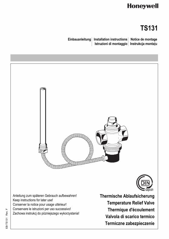
TS131Einbauanleitung Installation instructions Notice de montage
Istruzioni di montaggio Instrukcja monta|u
Anleitung zum späteren Gebrauch aufbewahren!Keep instructions for later use!Conserver la notice pour usage ultérieur!Conservare le istruzioni per uso successivo!Zachowa instrukcj do pózniejszego wykorzystania!
Thermische AblaufsicherungTemperature Relief ValveThermique d'écoulement
Valvola di scarico termicoTermiczne zabezpieczenie
EB-
TS13
1 R
ev. F

Honeywell GmbH 2 MU1H-1543GE23 R0913
D
1. Sicherheitshinweise1. Beachten Sie die Einbauanleitung.2. Benutzen Sie das Gerät
• bestimmungsgemäß• in einwandfreiem Zustand• sicherheits- und gefahrenbewusst.
3. Beachten Sie, dass das Gerät ausschließlich für den in dieser Einbauanleitung genannten Verwendungsbereich bestimmt ist. Eine andere oder darüber hinausgehende Benutzung gilt als nicht bestimmungsgemäß.
4. Beachten Sie, dass alle Montage-, Inbetriebnahme, Wartungs- und Justagearbeiten nur durch autorisierte Fachkräfte ausgeführt werden dürfen.
5. Lassen Sie Störungen, welche die Sicherheit beeinträch-tigen können, sofort beseitigen.
2. FunktionsbeschreibungDie thermische Ablaufsicherung wird von der Vorlauftempe-ratur des Wärmeerzeugers gesteuert. Sie besteht aus einem federbelasteten Ventil und einem Temperaturfühler, der auf ein Balgsystem wirkt. Erreicht die Vorlauftemperatur im Heiz-kessel die jeweilige Öffnungstemperatur (siehe Varianten) wird die Kraft im Balgsystem größer als die Federkraft des Ventiles, und das Ventil öffnet.Bei Installation vor dem Heizkessel in den Kaltwasserzu-lauf des im Heizkessel integrierten Wärmetauschers:Die thermische Ablaufsicherung verschließt damit die Zulei-tung zum Wärmetauscher, der Wärmetauscher selbst ist im normalen Betrieb trocken. Bei Öffnen der thermischen Ablaufsicherung wird der Wärmetauscher gefüllt und über die Wärmetauscherflächen die überschüssige Heizwärme aus dem Heizwasser frei in den Ablauf geleitet. Bei Installation hinter dem Heizkessel am Warmwasser-abgang: Die thermische Ablaufsicherung verschließt damit die Ablauf-leitung. Bei Öffnen der thermischen Ablaufsicherung wird das erwärmte Trinkwasser aus dem Wassererwärmer abgeführt und durch kaltes aus dem Netz ersetzt. Dieses kann nun die überschüssige Wärme aus dem Wassererwärmer aufnehmen und eine Überhitzung verhindern.
3. VerwendungFeststoff-/Wechselbrandkessel mit eingebautem Wasserer-wärmer oder Kühlschlange in geschlossenen Heizungsan-lagen nach EN 12828
4. Technische Daten
5. LieferumfangDie thermische Ablaufsicherung besteht aus:• Gehäuse mit Innengewinde• Haube• Ventilkegel mit Formdichtung• Feder• Externer Doppeltemperaturfühler mit Kapillarrohr• Tauchhülse G 1/2" (ISO 228)6. Varianten
7. Montage7.1. Einbauhinweise• Der Einbau des Ventiles und des Fühlers ist sorgfältig
vorzunehmen, damit Beschädigungen des Kapillarrohres vermieden werden
• Die Mündung der Ausblaseleitung muss frei und beobachtbar sein
• Personen dürfen beim Abblasen der Armatur nicht gefährdet werden
• Es ist eine ausreichend bemessene Ablaufleitung vorzu-sehen
7.2. Montageanleitung1. Thermische Ablaufsicherung entsprechend dem
Einbauschema einbauen• Durchflussrichtung ist durch Pfeil gekennzeichnet
2. Wärmefühler bis zum Anschlag in das Tauchrohr einschieben und mit der Rundkopfschraube gegen Herausziehen sichern
1 Sicherheitswärmetauscher2 Kaltwasserzulauf3 Ablauf4 min. DN20 (3/4")
Leistungen der Heizungsanlagen
max. 100 kW
Öffnungstemperatur siehe VariantenUmgebungstemperatur max. 70 °CLeistung 2800 kg/h Wasser bei einem Druck-
abfall von Δp=1 bar (Eingangsdruck 5bar; Ausgangsdruck 4bar) (1 Fühler)
Anschlussgröße Rp 3/4" (DIN EN 10226)Betriebsdruck max. 5 bar
TS131-3/4A = Öffnungstemperatur 95 °CKapillarrohr mit Schutzrohr 1300 mm bauteilgeprüft
TS131-3/4B = Öffnungstemperatur 95 °CKapillarrohr mit Schutzrohr 4000 mm
TS131-3/4ZAx = Öffnungstemperatur x = 50 °C / 100 °C oder 110 °CKapillarrohr mit Schutzrohr 1300 mm bauteilgeprüft
kvs-Wert Δp = 1 bar3 m3/h bei 2 unversehrten Fühlersystemen2,1 m3/h bei einem Fühlersystem
Achtung!Der Einbau der thermischen Ablaufsicherung ersetzt nicht das Membran-Sicherheitsventil in der Kalt-wasser-Zuführungsleitung zum Wassererwärmer.

MU1H-1543GE23 R0913 3 Honeywell GmbH
D
8. Inbetriebnahme
9. Instandhaltung
9.1. Inspektion und Wartung
1. Prüfen ob Wasser aus dem Gehäuse austritt• tritt Wasser aus müssen die Dichtungen (Kolbenfüh-
rung komplett) ersetzt oder das Gerät gegebenfalls ausgetauscht werden
2. Kontrollkappe betätigen und prüfen ob zunächst Wasser abläuft und das Ventil anschließend wieder schließt• tritt kein Wasser aus oder schließt das Ventil nicht muss
das Gerät gegebenfalls ausgetauscht werden9.2. Reinigung
10. Entsorgung• Gehäuse, Haube und Tauchhülse aus Messing• Temperaturfühler aus Kupfer• Kapillarrohr aus Kupfer• Ventilkegel aus Messing• Dichtungen aus heißwasserbeständigem Elastomer
11. Ersatzteile
Bei Inbetriebnahme der Heizungsanlage muss der Ersteller der Anlage die einwandfreie Funktion der ther-mischen Ablaufsicherung überprüfen.
Wir empfehlen einen Wartungsvertrag mit einem Instal-lationsunternehmen abzuschließen
• Entsprechend den Forderungen der DIN EN 12828 ist der Betreiber der Anlage verpflichtet, die thermi-sche Ablaufsicherung mindestens einmal jährlich durch einen Fachkundigen auf ihre Funktionsbereit-schaft prüfen zu lassen.
• Durchführung durch ein Installationsunternehmen
• Durchführung durch ein Installationsunternehmen• Durchführung durch den BetreiberZum Reinigen der Kunststoffteile keine lösungsmittel- und alkoholhaltige Reinigungsmittel benutzen!Es dürfen keine Reinigungsmittel in die Umwelt oder Kanalisation gelangen!
Die örtlichen Vorschriften zur ordnungsgemäßen Abfallverwertung bzw. Beseitigung beachten!
TS131K-3/4S Kolbenführung komplett für TS131Passend nur für Fertigungscharge ab 1141 (Jahr 2011, KW 41)
TS131TWG-3/4 Temperaturweggeber für TS131Öffnungstemperatur 95°CVariante A = Kapillarrohr mit Schutzrohr 1300 mmVariante B = Kapillarrohr mit Schutzrohr 4000 mmVariante ZAx = Öffnungstemperatur je nach Variante (x= 50°C oder100°C ), Kapillarrohr mit Schutzrohr 1300 mm
TS131IP-3/4 Tauchrohr für TS131
Honeywell GmbH 4 MU1H-1543GE23 R0913
GB
1. Safety Guidelines1. Follow the installation instructions.2. Use the appliance
• according to its intended use• in good condition• with due regard to safety and risk of danger.
3. Note that the appliance is exclusively for use in the appli-cations detailed in these installation instructions. Any other use will not be considered to comply with require-ments and would invalidate the warranty.
4. Please take note that any assembly, commissioning, servicing and adjustment work may only be carried out by authorized persons.
5. Immediately rectify any malfunctions which may influence safety.
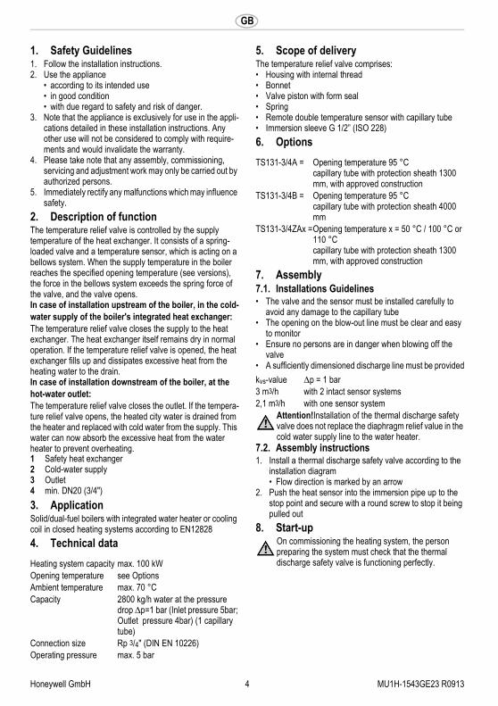
2. Description of functionThe temperature relief valve is controlled by the supply temperature of the heat exchanger. It consists of a spring-loaded valve and a temperature sensor, which is acting on a bellows system. When the supply temperature in the boiler reaches the specified opening temperature (see versions), the force in the bellows system exceeds the spring force of the valve, and the valve opens.In case of installation upstream of the boiler, in the cold-water supply of the boiler's integrated heat exchanger:The temperature relief valve closes the supply to the heat exchanger. The heat exchanger itself remains dry in normal operation. If the temperature relief valve is opened, the heat exchanger fills up and dissipates excessive heat from the heating water to the drain. In case of installation downstream of the boiler, at the hot-water outlet: The temperature relief valve closes the outlet. If the tempera-ture relief valve opens, the heated city water is drained from the heater and replaced with cold water from the supply. This water can now absorb the excessive heat from the water heater to prevent overheating.
3. ApplicationSolid/dual-fuel boilers with integrated water heater or cooling coil in closed heating systems according to EN128284. Technical data
5. Scope of deliveryThe temperature relief valve comprises:• Housing with internal thread• Bonnet• Valve piston with form seal• Spring• Remote double temperature sensor with capillary tube• Immersion sleeve G 1/2” (ISO 228)6. Options
7. Assembly7.1. Installations Guidelines• The valve and the sensor must be installed carefully to
avoid any damage to the capillary tube• The opening on the blow-out line must be clear and easy
to monitor• Ensure no persons are in danger when blowing off the
valve• A sufficiently dimensioned discharge line must be provided
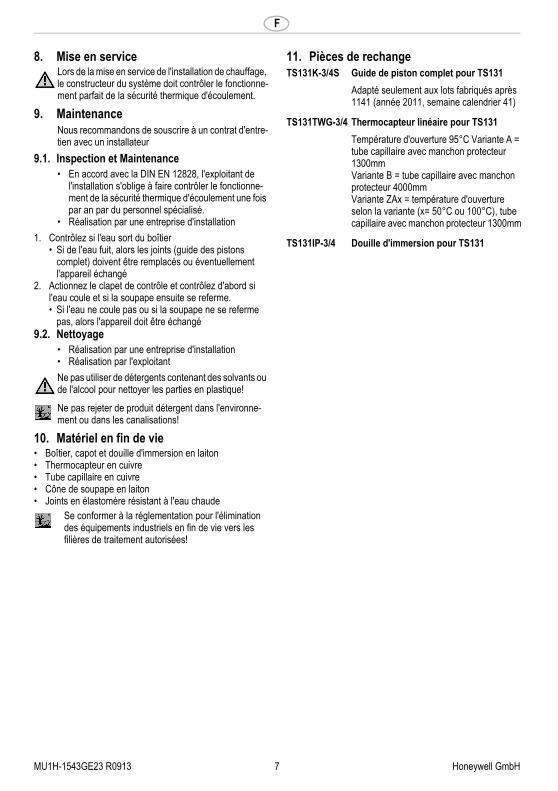
7.2. Assembly instructions1. Install a thermal discharge safety valve according to the
installation diagram• Flow direction is marked by an arrow
2. Push the heat sensor into the immersion pipe up to the stop point and secure with a round screw to stop it being pulled out
8. Start-up
1 Safety heat exchanger2 Cold-water supply3 Outlet4 min. DN20 (3/4")
Heating system capacity max. 100 kWOpening temperature see OptionsAmbient temperature max. 70 °CCapacity 2800 kg/h water at the pressure
drop Δp=1 bar (Inlet pressure 5bar; Outlet pressure 4bar) (1 capillary tube)
Connection size Rp 3/4" (DIN EN 10226)Operating pressure max. 5 bar
TS131-3/4A = Opening temperature 95 °Ccapillary tube with protection sheath 1300 mm, with approved construction
TS131-3/4B = Opening temperature 95 °Ccapillary tube with protection sheath 4000 mm
TS131-3/4ZAx =Opening temperature x = 50 °C / 100 °C or 110 °Ccapillary tube with protection sheath 1300 mm, with approved construction
kvs-value Δp = 1 bar3 m3/h with 2 intact sensor systems2,1 m3/h with one sensor system
Attention!Installation of the thermal discharge safety valve does not replace the diaphragm relief value in the cold water supply line to the water heater.
On commissioning the heating system, the person preparing the system must check that the thermal discharge safety valve is functioning perfectly.

MU1H-1543GE23 R0913 5 Honeywell GmbH
GB
9. Maintenance
9.1. Inspection and Maintenance
1. Check whether water is escaping from the housing• if water is escaping, the seals (piston guide complete)
must be replaced or if necessary the unit must be replaced
2. Operate the check valve and first check if water is running off, then close the valve again• if no water is escaping or the valve does not close, the
unit may have to be replaced9.2. Cleaning
10. Disposal• Brass housing, bonnet and immersion pocket• Copper temperature sensor• Copper capillary tube• Brass valve piston• Hot-water-resistant elastomer seals
11. Spare parts
We recommend a planned maintenance contract with an installation company
• According to the requirements of DIN EN 12828, the system operator is obliged to have the thermal discharge safety valve checked by a professional at least once a year to ensure its functioning capacity.
• To be carried out by an installation company
• To be carried out by an installation company• To be carried out by the operatorDo not use any cleaning agents containing solvents or alcohol to clean the plastic parts!Detergents must not be allowed to enter the environ-ment or the sewerage system!
Observe the local requirements regarding correct waste recycling/disposal!
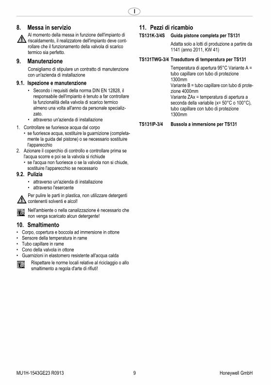
TS131K-3/4S Piston guide, complete, for TS131Only suitable for batches 1141 and up (2011, calendar week 41 and later)
TS131TWG-3/4 Thermal expansion element for TS131Opening temperature: 95° Type A = capillary with protection sleeve, 1300 mmType B = capillary with protection sheath 4000 mmType ZAx = opening temperature according to type (x = 50°C or 100°C ), capillary with protection sheath, 1300mm
TS131IP-3/4 Immersion sleeve for TS131

Honeywell GmbH 6 MU1H-1543GE23 R0913
F
1. Consignes de sécurité1. Suivre les indications de la notice de montage.2. En ce qui concerne l'utilisation de l'appareil
• Utiliser cet appareil conformément aux données du constructeur
• Maintenir l'appareil en parfait état• Respectez les consignes de sécurité
3. Il faut noter que cet équipement ne peut être mis en oeuvre que pour les conditions d'utilisation mentionnées dans cette notice. Toute autre utilisation, ou le non respect des conditions normales d'utilisation, serait consi-dérée comme non conforme.
4. Observer que tous les travaux de montage, de mise en service, d'entretien et de réglage ne pourront être effec-tués que par des spécialistes agréés.
5. Prendre des mesures immédiates en cas d'anomalies mettant en cause la sécurité.
2. Description fonctionelleLa sécurité thermique d'écoulement est pilotée par la tempé-rature de l'aller de la chaudière. Le dispositif comporte une soupape à ressort et une sonde de température qui agit sur un système de soufflet. Lorsque la température de l'aller atteint dans la chaudière la température d'ouverture corres-pondante (voir les variantes), la force du système de soufflet devient supérieure à l'élasticité de la soupape, par consé-quent la soupape s'ouvre.En cas d'installation en amont de la chaudière, dans l'arrivée d'eau froide de l'échangeur de chaleur intégré à la chaudière :La sécurité thermique d'écoulement obture ainsi la conduite d'arrivée de l'échangeur de chaleur, qui est sec en fonction-nement normal. L'ouverture de la sécurité thermique d'écou-lement provoque le remplissage de l'échangeur de chaleur, dont les surfaces dirigent ensuite la chaleur excédentaire que transporte l'eau de chauffage dans l'écoulement. En cas d'installation en aval de la chaudière, sur la sortie d'eau chaude : La sécurité thermique d'écoulement obture la conduite d'écoulement. L'ouverture de la sécurité d'écoulement provoque l'évacuation de l'eau potable chauffée hors du chauffe-eau, puis elle est remplacée par de l'eau froide issue du circuit. Cette eau peut alors prendre en charge la chaleur excédentaire provenant du chauffe-eau et empêcher ainsi une surchauffe.
3. Mise en oeuvreChaudière à combustible solide/chaudière mixte à chauffe-eau intégré ou serpentin de refroidissement dans des systèmes de chauffage fermés selon EN12828
4. Caractéristiques techniques
5. Contenu de la livraisonLa sécurité thermique d'écoulement se compose de :• Boîtier avec filetage intérieur• Capot• Cône de soupape avec joint• Ressort• Thermocapteur double externe avec tube capillaire• Douille d'immersion G 1/2" (ISO 228)6. Variantes
7. Montage7.1. Dispositions à prendre• Le montage de la soupape et du capteur doit être effectué
prudemment afin de ne pas endommager le tube capil-laire.
• L'embouchure de la conduite de sortie doit être libre et observable
• Les personnes ne doivent pas être mises en danger par le crachement de la robinetterie
• Il convient de prévoir une conduite d'écoulement suffisante
7.2. Instructions de montage1. Montez la sécurité thermique d'écoulement, selon le plan
de montage• La direction du courant est marquée par une flèche
2. Glissez les thermocapteur dans la douille d'immersion jusqu'à la butée et sécurisez avec une vis à tête ronde
1 Échangeur de chaleur de sécurité2 Arrivée d'eau froide3 Évacuation4 min. DN20 (3/4")
Puissances de l'installa-tion de chauffage
max. 100 kW
Température d'ouverturevoir VariantesTempérature ambiante max. 70 °CDébit 2800 kg/h d’eau pour une perte de
charge Δp=1 bar (Pression d’entrée 5bar; Pression de sortie 4bar) (1 tube capillaire)
Dimensions de raccordement
Rp 3/4" (DIN EN 10226)
Pression de service max. 5 bar
TS131-3/4A = Température d'ouverture 95º CTube capillaire avec protection 1300 mm testé
TS131-3/4B = Température d'ouverture 95º CTube capillaire avec protection 4000 mm
TS131-3/4ZAx =Température d'ouverture x = 50 °C / 100 °C ou 110 °CTube capillaire avec protection 1300 mm testé
Valeur du kvs Δp = 1 bar3 m3/h avec 2 systèmes intacts de capteurs2,1 m3/h avec un système de capteurs
Attention !Le montage de la sécurité thermique d'écoulement ne remplace pas la soupape de sécurité à membrane dans la conduite d'alimentation d'eau froide vers le chauffe-eau.
MU1H-1543GE23 R0913 7 Honeywell GmbH
F
8. Mise en service
9. Maintenance
9.1. Inspection et Maintenance
1. Contrôlez si l'eau sort du boîtier• Si de l'eau fuit, alors les joints (guide des pistons
complet) doivent être remplacés ou éventuellement l'appareil échangé
2. Actionnez le clapet de contrôle et contrôlez d'abord si l'eau coule et si la soupape ensuite se referme.• Si l'eau ne coule pas ou si la soupape ne se referme
pas, alors l'appareil doit être échangé9.2. Nettoyage
10. Matériel en fin de vie• Boîtier, capot et douille d'immersion en laiton• Thermocapteur en cuivre• Tube capillaire en cuivre• Cône de soupape en laiton• Joints en élastomère résistant à l'eau chaude
11. Pièces de rechangeLors de la mise en service de l'installation de chauffage, le constructeur du système doit contrôler le fonctionne-ment parfait de la sécurité thermique d'écoulement.
Nous recommandons de souscrire à un contrat d'entre-tien avec un installateur
• En accord avec la DIN EN 12828, l'exploitant de l'installation s'oblige à faire contrôler le fonctionne-ment de la sécurité thermique d'écoulement une fois par an par du personnel spécialisé.
• Réalisation par une entreprise d'installation
• Réalisation par une entreprise d'installation• Réalisation par l'exploitantNe pas utiliser de détergents contenant des solvants ou de l'alcool pour nettoyer les parties en plastique!
Ne pas rejeter de produit détergent dans l'environne-ment ou dans les canalisations!
Se conformer à la réglementation pour l'élimination des équipements industriels en fin de vie vers les filières de traitement autorisées!
TS131K-3/4S Guide de piston complet pour TS131Adapté seulement aux lots fabriqués après 1141 (année 2011, semaine calendrier 41)
TS131TWG-3/4 Thermocapteur linéaire pour TS131Température d'ouverture 95°C Variante A = tube capillaire avec manchon protecteur 1300mmVariante B = tube capillaire avec manchon protecteur 4000mmVariante ZAx = température d'ouverture selon la variante (x= 50°C ou 100°C), tube capillaire avec manchon protecteur 1300mm
TS131IP-3/4 Douille d'immersion pour TS131

Honeywell GmbH 8 MU1H-1543GE23 R0913
I
1. Avvertenze di sicurezza1. Rispettare le istruzioni di montaggio.2. Utilizzare l'apparecchio
- secondo la destinazione d'uso- solo se integro- in modo sicuro e consapevoli dei pericoli connessi
3. Si prega di considerare che l'apparecchio è realizzato esclusivamente per il settore d'impiego riportato nelle presenti istruzioni d'uso. Un uso differente o diverso da quello previsto è da considerarsi improprio.
4. Osservare che tutti i lavori di montaggio, di messa in funzione, di manutenzione e di regolazione devono essere eseguiti soltanto da tecnici specializzati e autoriz-zati.
5. I guasti che potrebbero compromettere la sicurezza devono essere risolti immediatamente.
2. Descrizione del funzionamentoLa valvola di scarico termico è comandata dalla temperatura di mandata del generatore di calore ed è formata da una valvola caricata a molla e da un sensore termico che agisce su un sistema a soffietto. Quando la temperatura di mandata nella caldaia raggiunge la corretta temperatura di apertura (vedere varianti) la forza nel sistema a soffietto supera quella della molla della valvola, la quale si apre.Installazione davanti alla caldaia nel tubo di mandata dell'acqua fredda dello scambiatore di calore integrato nella caldaia:la valvola di scarico termico chiude l'alimentazione dello scambiatore di calore, il quale in normali condizioni d'eser-cizio è asciutto. Aprendo la valvola di scarico termico, lo scambiatore di calore si riempie e il calore in eccesso viene condotto con l'acqua di riscaldamento allo scarico tramite le superfici dello scambiatore di calore. Installazione davanti alla caldaia all'uscita dell'acqua calda: la valvola di scarico termico chiude la linea di scarico. Aprendo la valvola di scarico termico l’acqua potabile riscal-data viene fatta defluire dallo scaldacqua e sostituita da acqua fredda della rete. Questa può quindi assorbire il calore in eccesso prodotto dallo scaldacqua ed evitare un surris-caldamento.
3. UsoCaldaia a combustibili solidi / per due combustibili con scal-dacqua integrato o serpentina refrigerante in impianti di riscaldamento chiusi in conformità alla normativa europea EN12828
4. Dati tecnici
5. FornituraLa valvola di scarico termico è composta da:• Corpo con filettatura interna• Copertura• Cono della valvola con guarnizione sagomata• Molla• Doppio sensore di temperatura esterno con tubo capillare• Bussola a immersione G1/2" (ISO 228)6. Varianti
7. Montaggio7.1. Istruzioni di installazione• Il montaggio della valvola e del sensore deve essere
eseguito con attenzione per evitare danni al tubo capillare• La bocca del tubo di scarico deve essere libera e visibile• Non mettere in pericolo le persone durante lo scarico della
valvola• Prevedere un tubo di scarico della misura adeguata
7.2. Istruzioni di montaggio1. Montare la valvola di scarico termico secondo lo schema
di montaggio • La direzione di flusso è indicata dalla freccia
2. Inserire il termorivelatore nel tubo ad immersione fino all'arresto e assicurarlo con la vite a testa tonda in modo che non esca
1 Scambiatore di calore di sicurezza2 Tubo di mandata acqua fredda3 Scarico4 min. DN20 (3/4")
Prestazioni degli impi-anti di riscaldamento
max. 100 kW
Temperatura di aperturavedi VariantiTemperatura ambiente max. 70 °CPrestazione 2800 kg/h di acqua con una caduta
di pressione Δp=1 bar (pressione in ingresso 5 bar; pressione in uscita 4 bar) (1 sensore)
Dimensioni attacchi Rp 3/4" (DIN EN 10226)Pressione di esercizio max. 5 bar
TS131-3/4A = Temperatura di apertura 95°CTubo capillare con guaina protettiva da 1300 mm, con struttura controllata
TS131-3/4B = Temperatura di apertura 95°CTubo capillare con guaina protettiva da 4000 mm
TS131-3/4ZAx = Temperatura di apertura x = 50 °C / 100 °C o 110 °CTubo capillare con guaina protettiva da 1300 mm, con struttura controllata
kvsValore Δp = 1 bar3 m3/h con due sistemi di sensori integri2,1 m3/h con un sistema di sensori
Attenzione!Il montaggio della valvola di scarico termico non sostituisce la valvola di sicurezza a memb-rana nella condotta di alimentazione dell'acqua fredda verso il generatore dell'acqua.
MU1H-1543GE23 R0913 9 Honeywell GmbH
I
8. Messa in servizio
9. Manutenzione
9.1. Ispezione e manutenzione
1. Controllare se fuoriesce acqua dal corpo• se fuoriesce acqua, sostituire la guarnizione (completa-
mente la guida del pistone) o se necessario sostituire l'apparecchio
2. Azionare il coperchio di controllo e controllare prima se l'acqua scorre e poi se la valvola si richiude• se l'acqua non fuoriesce o se la valvola non si chiude,
sostituire l'apparecchio se necessario9.2. Pulizia
10. Smaltimento• Corpo, copertura e boccola ad immersione in ottone• Sensore della temperatura in rame• Tubo capillare in rame• Cono della valvola in ottone• Guarnizioni in elastomero resistente all'acqua calda
11. Pezzi di ricambioAl momento della messa in funzione dell'impianto di riscaldamento, il realizzatore dell'impianto deve cont-rollare che il funzionamento della valvola di scarico termico sia perfetto.
Consigliamo di stipulare un contratto di manutenzione con un'azienda di installazione
• Secondo i requisiti della norma DIN EN 12828, il responsabile dell'impianto è tenuto a far controllare la funzionalità della valvola di scarico termico almeno una volta all'anno da personale specializ-zato.
• attraverso un'azienda di installazione
• attraverso un'azienda di installazione• attraverso l'esercentePer pulire le parti in plastica, non utilizzare detergenti contenenti solventi e alcol!Nell'ambiente o nella canalizzazione è necessario che non venga scaricato alcun detergente!
Rispettare le norme locali relative al riciclaggio o allo smaltimento a regola d'arte di rifiuti!
TS131K-3/4S Guida pistone completa per TS131Adatta solo a lotti di produzione a partire da 1141 (anno 2011, KW 41)
TS131TWG-3/4 Trasduttore di temperatura per TS131Temperatura di apertura 95°C Variante A = tubo capillare con tubo di protezione 1300mmVariante B = tubo capillare con tubo di prote-zione 4000mmVariante ZAx = temperatura di apertura a seconda della variabile (x= 50°C o 100°C), tubo capillare con tubo di protezione 1300mm
TS131IP-3/4 Bussola a immersione per TS131
Honeywell GmbH 10 MU1H-1543GE23 R0913
PL
1. Wskazówki bezpieczeDstwa1. Przestrzegaę instrukcji montażu.2. Proszę użytkowaę urządzenie
• zgodnie z jego przeznaczeniem• w nienagannym stanie• ze świadomością bezpieczeństwa i zagrożeń
3. Proszę uwzględnię, że urządzenie przeznaczony jest wyłącznie dla zakresu zastosowania określonego w niniejszej instrukcji montażu. Każde inne lub wykraczające poza to użytkowanie uznawane jest jako niezgodne z przeznaczeniem.
4. Proszę uwzględnię, że wszystkie prace montażowe mogą byę wykonywane tylko przez autoryzowany personel fachowy.
5. Wszystkie usterki, które mogą naruszyę bezpiec zeństwo należy natychmiast usunąę.
2. Opis funkcjiTemperatura dopływu w generatorze ciepła reguluje termiczne zabezpieczenie odpływu. Termiczne zabezpieczenie składa się ze sprężynowego zaworu oraz czujnika temperatury oddziaływującego na system mieszkowy. Przy odpowiedniej wartości temperatury otwarcia w dopływie kotla grzewczego (patrz warianty), wartość siły w systemie mieszkowym osiąga wyższy poziom aniżeli siła sprężyny zaworu. Zawór otwiera się.Podczas instalacji przed kotłem grzewczym przy dopływie zimnej wody zainstalowanego w kotle wymiennika ciepła:Termiczne zabezpieczenie odpływu zamyka przewód wymiennika ciepła. W normalnym trybie pracy wymiennik ciepła pozostaje suchy. Podczas otwierania termicznego zabezpieczenia odpływu następuje napełnienie wymiennika ciepła. Jednocześnie nadmiar ciepła podgrzanej wody zostaje odprowadzona przez wymiennik ciepła do odpływu. Podczas instalacji za kotem grzewczym przy ujciu ciepej wody: Termiczne zabezpieczenie odpywu zamyka przewód odpywu. Podczas otwierania termicznego zabezpieczenia odpywu, podgrzana woda pitna zostaje odprowadzona z podgrzewacza wody a nastpnie wymieniona na zimn wod z sieci. Zimna woda jest w stanie wchon nadmiar ciepa z podgrzewacza wody i w ten sposób zapobiec jego przegrzaniu.
3. ZastosowanieKoty na paliwa stae / koty do zmiennego spalania z wbudowanym podgrzewaczem wody lub wownic chodzc w zamknitych instalacjach grzewczych skonstruowanych zgodnie z norm EN12828
4. Dane techniczne
5. Zakres dostawyZabezpieczenie termiczne składa się:• Korpus z gwintem wewnętrznym• Osłona• Grzybek zaworu z profilowanym uszczelnieniem • Sprężyna• Zewnętrzny podwójny czujnik temperatury z rurką kapi
larną• Tulejka zanurzeniowa G 1/2" (ISO 228)6. Warianty
7. Montaż7.1. Montaż• Montaż zaworu oraz czujnikanależy przeprowadzić w
staranny sposób, tak by nie uszkodzić rurki kapi larnej• Wylot przewodu wydmuchowego nie może być zatkany
i musi być widoczny• Wydmuchiwanie armatury nie może stanowić
zagrożenia dla osób• Należy zastosować przewód odprowadzający od
odpowiednich wymiarach
7.2. Instrukcja montażu1. Zainstalowa termiczne zabezpieczenie odpywu
zgodnie ze wskazówkami na schemacie instalacyjnym• Kierunek przepływu oznaczono strzałką
2. Czujnik termiczny wsunąć do oporu w rurkę zanurzeniową zabezpieczyć przed wyciagnięciem śrubą
1 Zabezpieczenie wymiennika ciepła2 Dopyw zimnej wody3 Odpyw4 min. DN20 (3/4")
Moc instalacji grzewczej
max. 100 kW
Temperatura otwarcia widział WariantyTemperatura otoczenia max. 70 °CPrzepływ 2800 kg/h wody przy spadku ciśni
enia Δp=1 bar (Ciśnienie wejściowe 5 bar; Ciśnienie wyjściowe 4 bar) (1 rurka kapilarna).
Rozmiar przyłącza Rp 3/4" (DIN EN 10226)Ciśnienie robocze max. 5 bar
TS131-3/4A = Temperatura otwarcia 95 °CRurka kapilarna z rurką ochronną 1300 mm certyfikowana
TS131-3/4B = Temperatura otwarcia 95 °CRurka kapilarna z rurką ochronną 4000 mm
TS131-3/4ZAx =Temperatura otwarcia x = 50 °C / 100 °C / 110 °CRurka kapilarna z rurką ochronną 1300 mm certyfikowana
Wartośę kvs Δp = 1 bar3 m3/h przy 2 sprawnych systemach czujników2,1 m3/h przy jednym systemie czujników
Uwaga!Montaż zabezpieczenia termicznego nie zastępuje przeponowego zaworu bezpiec zeństwa w układzie doprowadzającym wodę zimną do podgrzewacza wody.

MU1H-1543GE23 R0913 11 Honeywell GmbH
PL
8. Uruchomienie
9. Utrzymywanie w dobrym stanie
9.1. Inspekcja i Konserwacja
1. Należy sprawdzić, czy z korpusu nie wycieka woda• w przypadku wycieku wody należy wymienić uszc
zelnienia (zespół tłoka - komplet) lub w razie potrzeby całe urządzenie
2. Uruchomić pokrywę kontrolną i sprawdzić czy odpływa woda a zawór następnie ponownie zamyka• jeżeli nie wypływa woda lub zawór nie zamyka
urządzenie należy wymienić9.2. Czyszczenie
10. Usuwanie• Korpus, osłona i tulejka zanurzeniowa z mosiądzu• Czujnik temperatury z miedzi• Rurka kapilarna z miedzi• Grzybek zaworu z mosiądzu• Uszczelnienia z odpornych na działanie gorącej wody
elastomerów
11. Części zamiennePrzed oddaniem instalacji do użytku wykwalifi kowany instalator powinien sprawdzić popraw ność działania zabezpieczenia termicznego.
Zalecamy zawarcie umowy konserwacyjnej z odpowiednią firmą instalacyjną
• Zgodnie z wymogami normy DIN EN 12828 użytkujący instalację ma obowiązek zlecić wykwalifikowanemu instalatorowi przynajm niej raz w roku kontrolę poprawności działania zabezpieczenia termicznego.
• Kontrole powinna przeprowadzię firma instala cyjna
• Kontrole powinna przeprowadzię firma instala cyjna
• Przeprowadzane przez użytkującegoDo czyszczenia czÍúci z tworzywa sztucznego nie uřywaĘ úrodkŰw do czyszczenia, zawierajĽcych rozpuszczalniki i alkohol!Żadne środki czyszczące nie powinny dostaę się do środowiska naturalnego lub kanalizacji!
Należy stosowaę się do miejscowych przepisów dotyczących prawidłowego wykorzystania odpadów wzgl. ich usuwania!
TS131K-3/4S Kompletne prowadzenie toka dostosowane do TS131Jedynie do serii produkcyjnej od 1141 (rok produkcji 2011, 41. tydzie kalendarzowy)
TS131TWG-3/4 Termostat dostosowany do TS131Temperatura podczas otwierania 95C Wariant A = rurka kapilarna z rurk ochronn 1300mmWariant B = rurka kapilarna z rurk ochronn 4000mmWariant ZAx = temperatura podczas otwierania uzaleniona od wariantu (x= 50°C lub 100°C), rurka kapilarna z rurk ochronn 1300mm
TS131IP-3/4 Tulejka zanurzeniowa do TS131

Automation and Control Solutions
Honeywell GmbHHardhofweg74821 MOSBACHGERMANYPhone: (49) 6261 810Fax: (49) 6261 81309http://ecc.emea.honeywell.com
Manufactured for and on behalf of the Environmental and Combustion Controls Division of Honeywell Technologies Sàrl, Z.A. La Pièce 16, 1180 Rolle, Switzerland by its Authorised Represen-tative Honeywell GmbH
EN0H-1543GE23 R0913Subject to change© 2013 Honeywell GmbH

MU1H-1543GE23 R0913 Honeywell GmbH
2.
3
1
2
4
3
4
TS131K-3/4S TS131TWG-3/4 TS131IP-3/4AS
11.

MU1H-1543GE23 R0913 Honeywell GmbH
D1. Sicherheitshinweise ........................... 21. Funktionsbeschreibung ..................... 22. Verwendung ....................................... 23. Technische Daten .............................. 24. Lieferumfang ...................................... 25. Varianten ............................................ 26. Montage ............................................. 27. Inbetriebnahme .................................. 38. Instandhaltung ................................... 39. Entsorgung ......................................... 310. Ersatzteile .......................................... 3
GB1. Safety Guidelines ............................... 411. Description of function ...................... 412. Application ......................................... 413. Technical data ................................... 414. Scope of delivery ............................... 415. Options ............................................... 416. Assembly ............................................ 417. Start-up .............................................. 418. Maintenance ...................................... 519. Disposal ............................................. 520. Spare Parts ........................................ 5
F1. Consignes de sécurité ....................... 621. Description fonctionelle .................... 622. Mise en oeuvre .................................. 623. Caractéristiques ................................ 624. Contenu de la livraison ...................... 625. Variantes ............................................ 626. Montage ............................................. 627. Mise en service .................................. 728. Maintenance ...................................... 729. Matériel en fin de vie ......................... 730. Pièces de rechange ........................... 7
I1. Avvertenze di sicurezza .................... 831. Descrizione del funzionamento ........ 832. Uso ..................................................... 833. Dati tecnici ......................................... 834. Fornitura ............................................. 835. Varianti ............................................... 836. Montaggio .......................................... 837. Messa in servizio ............................... 938. Manutenzione .................................... 939. Smaltimento ....................................... 940. Ricambi .............................................. 9
PL1. Wskazówki bezpieczeDstwa .....................102. Opis funkcji .................................................103. Zastosowanie .............................................104. Dane techniczne .........................................105. Zakres dostawy ..........................................106. Warianty ......................................................107. Montaż .........................................................108. Uruchomienie .............................................119. Utrzymywanie w dobrym stanie ................1110. Usuwanie ....................................................1111. Części zamienne ........................................11