Embed Size (px)
Citation preview
820
EMOD Motoren GmbH
Elektromotorenfabrik Zur Kuppe 1 36364 Bad Salzschlirf DeutschlandFon: +49 6648 51-0 Fax: +49 6648 51-143 [email protected] www.emod-motoren.de
Single-phase motors Degree of protection IP 55
Einphasenmotoren IP 55
2
Allgemeine technische Erläuterungen
Leistungstabellen Typ EHB
Leistungstabellen Typ EAZR
Maßtabellen Typ EHB / EAZR
Klemmkasten-Maße
Lieferbare Flansche
Katalog 820 / Ausgabe 2018Inhaltsverzeichnis
4 –15
16
17
18 – 20
21
22
Seite
Lieferbedingungen
Unseren Lieferungen und Leistungen liegen unsere Verkaufs- und Lieferbedingungen sowie die allgemeinen Lieferbedingungen für Erzeugnisse und Leistungen der Elektroindustrie zugrunde.
Änderungen der in der Liste angegebenen technischen Daten sowie Maße und Gewichte bleiben vorbehalten.
Reklamationen können nur innerhalb 8 Tagen nach Empfang der Ware berücksichtigt werden.
Preise
Unsere Preise gelten ab Werk, ausschließlich Verpackung, zuzüglich der gesetzlich vorgeschriebenen Mehrwertsteuer.
Verpackung wird nicht zurückgenommen.
Preisänderungen bleiben vorbehalten. Der Berechnung werden jeweils die am Tage der Lieferung gültigen Preise zugrunde gelegt.
Kupferzuschläge
Kupferpreis lt. DEL-Notiz€ / 100 kg
Kupferzuschlag%
231,– bis 281,– 1,20 %
282,– bis 332,– 2,50 %
333,– bis 383,– 3,50 %
384,– bis 435,– 4,50 %
436,– bis 486,– 5,50 %
487,– bis 537,– 6,50 %
538,– bis 588,– 7,50 %
589,– bis 639,– 8,50 %
640,– bis 690,– 9,50 %
3
4 –15
16
17
18 – 20
21
22
General technical information
Rated output EHB
Rated output EAZR
Dimension sheets EHB / EAZR
Terminal box dimensions
Available flanges
Page
Catalogue 820 / Edition 2018Contents
Copper surcharge
Copper price€ / 100 kg
Price increase%
231.– to 281.– 1.20 %
282.– to 332.– 2.50 %
333.– to 383.– 3.50 %
384.– to 435.– 4.50 %
436.– to 486.– 5.50 %
487.– to 537.– 6.50 %
538.– to 588.– 7.50 %
589.– to 639.– 8.50 %
640.– to 690.– 9.50 %
Conditions of sale and delivery
Our supplies and services are subject to our own conditions of sale and delivery and the general conditions of supply and delivery for the products and services of the electrical industry.
The technical data, dimensions and weights given in this catalogue are subject to change without notice.
Any claims must be made within 8 days of the receipt of goods.
Prices
The prices quoted are ex-works, not including packing, plus value added tax at the current rate.
Packing materials are non-returnable.
The right is reserved to modify prices at any time. The prices charged are those ruling on the day of despatch.
4
Allgemeine technische Erläuterungen
Kondenswasserablauflöcher
Die katalogmäßigen Motoren in der Schutzart IP 55 haben keine Kondenswasserablauflöcher.
Bei Aufstellung im Freien, extremen klimatischen Verhältnissen oder Aussetzbetrieb sind die Motoren durch Kondensatbildung gefährdet.
Auf besonderen Wunsch können Kondenswasserablauf löcher an der tiefsten Stelle des Motors angebracht werden.
Bei Lieferung der Motoren sind diese mit Verschlussstopfen versehen.
Die Lage der Löcher richtet sich nach Einbaulage des Motors und muss bei der Bestellung genau angegeben werden.
Bei Flanschmotoren mit Wellenende nach oben können auf Wunsch Wasserablauföffnungen in den Flanschhals einge-bracht werden.
Kühlung und Belüftung
Die Motoren haben Eigenventilatoren, die unab hängig von der Drehrichtung des Motors kühlen (Kühlart IC 411 nach DIN EN 60034-6).
Bei Aufstellung der Motoren ist darauf zu achten, dass ein Mindest-abstand von Lüfterhaube zu Wand eingehalten wird um die Luft-zuführung zu gewährleisten (siehe vorher Maß l von Lüfterhaube zu Schutzdach).
Stillstandsheizung
Bei Motoren, die starken Temperaturschwankungen oder extremen klimatischen Verhältnissen ausgesetzt sind, ist die Motorwicklung durch Kondensatbildung oder Betauung gefährdet. Als Option kann eine eingebaute Stillstandsheizung die Motor-wicklung nach dem Abschalten erwärmen und einen Feuchtig-keitsniederschlag im Motorinneren verhindern.
Normen und Vorschriften
Die Motoren entsprechen den einschlägigen Normen und Vorschriften. Insbesondere werden folgende erwähnt:
Titel DIN EN / IEC
Drehende elektrische Maschinen. Bemessung und Betriebsverhalten
60034 -1
Einteilung der Schutzarten 60034 -5
Einteilung der Kühlverfahren (IC Code) 60034 -6
Bezeichnung für Bauform und Aufstellung (IM-Code)
60034 -7
Anschlussbezeichnung und Drehsinn 60034 -8
Schutzarten
Alle Motoren und Anschlusskästen sind in der Schutz art IP 55 nach DIN EN 60034-5 ausgeführt.
Die Motoren sind entsprechend der Norm für die Aufstellung in staubiger und feuchter Umgebung geeignet.
Bei Aufstellung im Freien sind die Motoren vor intensiver Sonnen-einstrahlung zu schützen.
Motoren mit Wellenende nach oben müssen vom An wender vor Eindringen von Wasser entlang der Welle geschützt werden.
Für besondere Anwendungsfälle kann auf Wunsch die Schutzart der Motoren durch Zusatzmaßnahmen erhöht werden (IP W55).
Während des Betriebes darf die Stillstandsheizung nicht einge-schaltet werden.
Baugröße Heizleistung Anschlussspannung
W V V
63 – 80 25 230 110
90 – 112 50 230 110
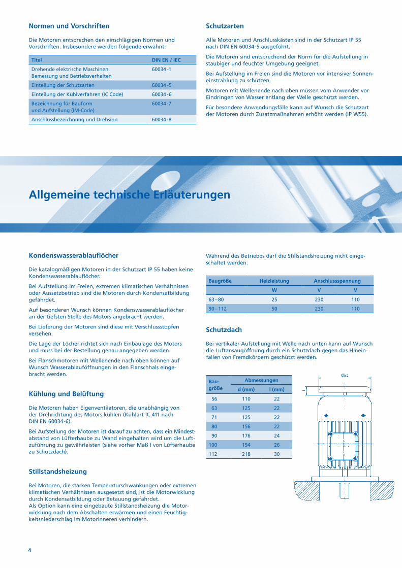
Schutzdach
Bei vertikaler Aufstellung mit Welle nach unten kann auf Wunsch die Luftansaugöffnung durch ein Schutzdach gegen das Hinein-fallen von Fremdkörpern geschützt werden.
Bau- größe
Abmessungen
d (mm) l (mm)
56 110 22
63 125 22
71 125 22
80 156 22
90 176 24
100 194 26
112 218 30
5
General technical information
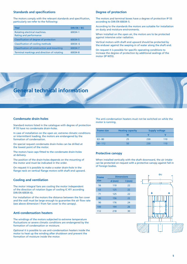
Condensate drain-holes
Standard motors listed in the catalogue with degree of protection IP 55 have no condensate drain-holes.
In case of installation on the open air, extreme climatic conditions or intermittent loading, the motors are endangered by the formation of condensation.
On special request condensate drain-holes can be drilled at the lowest point of the motor.
The motors have caps fitted to the condensate drain-holes at delivery.
The position of the drain-holes depends on the mounting of the motor and must be indicated in the order.
On request it is possible to make a water drain-hole in the flange neck on vertical flange motors with shaft end upward.
Cooling and ventilation
The motor integral fans are cooling the motor independent of the direction of rotation (type of cooling IC 411 according DIN EN 60034-6).
For installation of the motors the distance between the fan cover and the wall must be large enough to guarantee the air flow rate (see above dimension l from fan cover to the canopy).
Anti-condensation heaters
The windings of the motors subjected to extreme temperature fluctuations or severe climatic conditions are endangered by the formation of condensation or moisture.
Optional it is possible to use anti-condensation heaters inside the motor to heat up the winding after shutdown and prevent the formation of moisture inside the motor.
Standards and specifications
The motors comply with the relevant standards and specification, particularly we refer to the following:
Titel DIN EN / IEC
Rotating electrical machines. Rating and performance
60034-1
Classification of degree of protection 60034-5
Classification of cooling methods 60034 -6
Classification of construction and mounting 60034-7
Terminal markings and direction of rotating 60034-8
Degree of protection
The motors and terminal boxes have a degree of protection IP 55 according to DIN EN 60034-5.
According to the standards the motors are suitable for installation on dusty and moisture environments.
When installed on the open air, the motors are to be protected against intensive solar radiation.
Vertical motors with shaft end upward should be protected by the enduser against the seeping-in of water along the shaft end.
On request it is possible for specific operating conditions to increase the degree of protection by additional sealings of the motor (IP W55).
The anti-condensation heaters must not be switched on while the motor is running.
Frame size Heating capacity Supply voltage
W V V
63 – 80 25 230 110
90 – 112 50 230 110
Protective canopy
When installed vertically with the shaft downward, the air intake can be protected on request with a protective canopy against fall-in of foreign bodies.
Frame size
Dimensions
d (mm) l (mm)
56 110 22
63 125 22
71 125 22
80 156 22
90 176 24
100 194 26
112 218 30
6
Allgemeine technische Erläuterungen
Bremsmotoren
Die in der Liste angegebenen Einphasenmotoren können durch Anbau einer Federkraftbremse zu Bremsmotoren erweitert werden.
Die angebaute Einscheiben-Federkraftbremse ist eine Sicherheits-bremse, die durch Federkraft bei abgeschalteter Spannung bremst.
Die Gleichstrom-Bremsspule wird über einem im Klemmkasten eingebauten Gleichrichter gespeist.
Der Motor darf nur in Verbindung mit der Gleichstrombremse eingeschaltet werden.
Alle weiteren technischen Angaben zu Bremsen siehe Haupt-katalog 821, jeweils gültige Version.
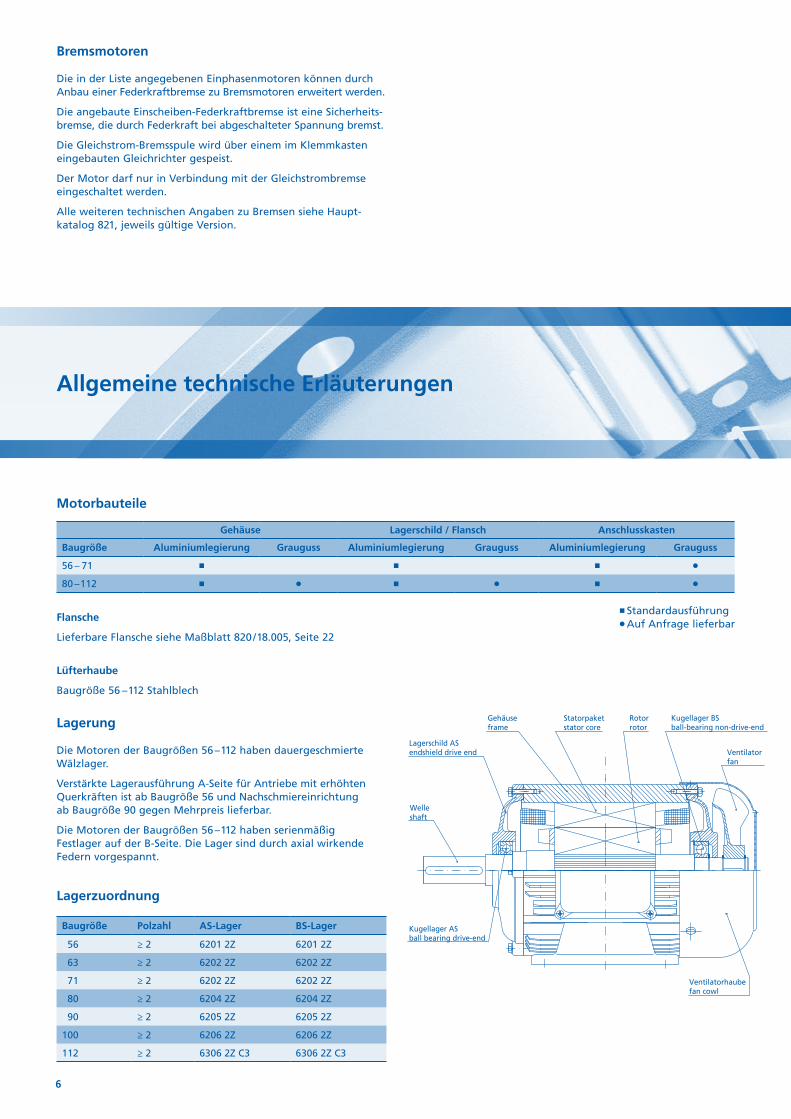
Motorbauteile
Gehäuse Lagerschild / Flansch Anschlusskasten
Baugröße Aluminiumlegierung Grauguss Aluminiumlegierung Grauguss Aluminiumlegierung Grauguss
56 – 71 P
80 – 112 P P P
Standardausführung P Auf Anfrage lieferbar
Flansche
Lieferbare Flansche siehe Maßblatt 820 / 18.005, Seite 22
Lüfterhaube
Baugröße 56 – 112 Stahlblech
Lagerung
Die Motoren der Baugrößen 56 – 112 haben dauergeschmierte Wälzlager.
Verstärkte Lagerausführung A-Seite für Antriebe mit erhöhten Querkräften ist ab Baugröße 56 und Nachschmier einrichtung ab Baugröße 90 gegen Mehrpreis lieferbar.
Die Motoren der Baugrößen 56 – 112 haben serienmäßig Fest lager auf der B-Seite. Die Lager sind durch axial wirkende Federn vorgespannt.
Lagerzuordnung
Baugröße Polzahl AS-Lager BS-Lager
56 ≥ 2 6201 2Z 6201 2Z
63 ≥ 2 6202 2Z 6202 2Z
71 ≥ 2 6202 2Z 6202 2Z
80 ≥ 2 6204 2Z 6204 2Z
90 ≥ 2 6205 2Z 6205 2Z
100 ≥ 2 6206 2Z 6206 2Z
112 ≥ 2 6306 2Z C3 6306 2Z C3
Lagerschild ASendshield drive end
Welleshaft
Gehäuseframe
Statorpaketstator core
Rotorrotor
Kugellager BSball-bearing non-drive-end
Ventilatorfan
Ventilatorhaubefan cowl
Kugellager ASball bearing drive-end
Klemmenkastenrahmenterminal box frame
Klemmenkastendeckelterminal box cover
Kondensatorcapacitor
7
General technical information
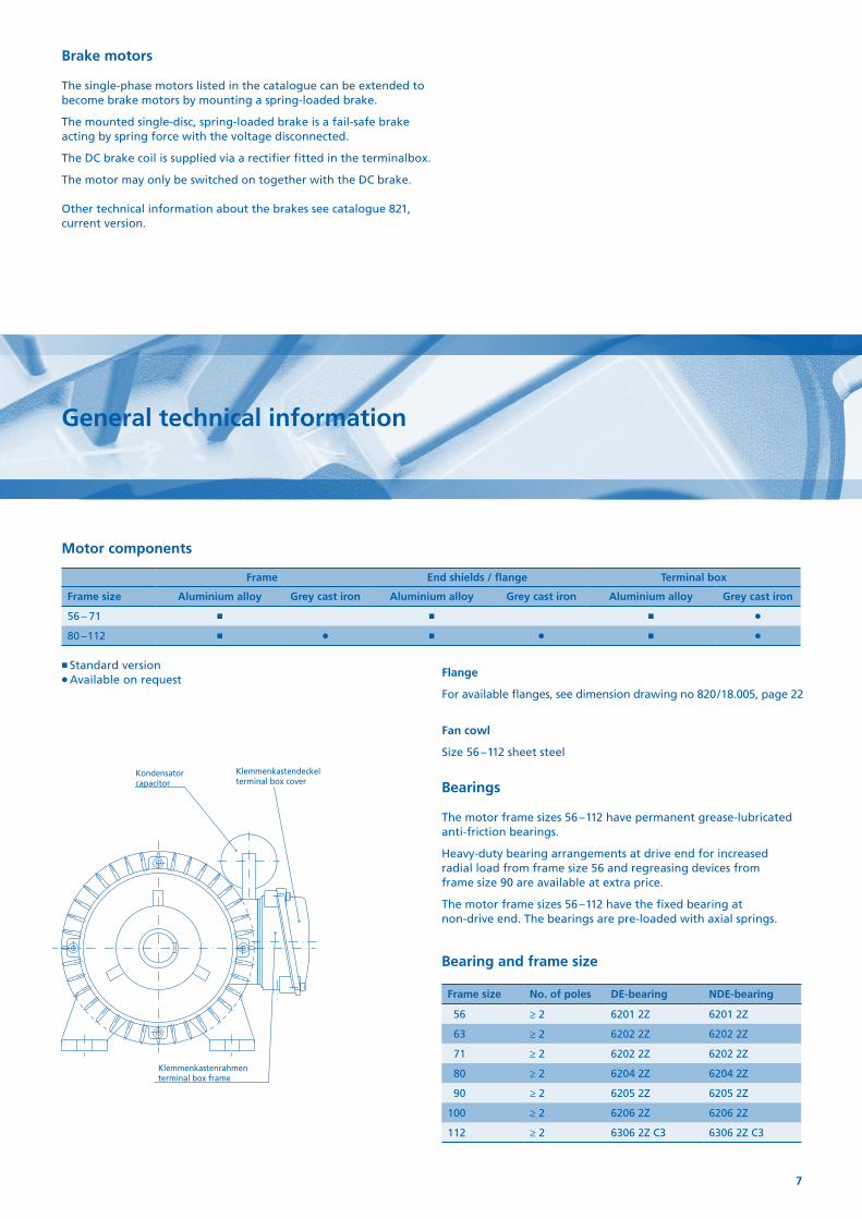
Brake motors
The single-phase motors listed in the catalogue can be extended to become brake motors by mounting a spring-loaded brake.
The mounted single-disc, spring-loaded brake is a fail-safe brake acting by spring force with the voltage disconnected.
The DC brake coil is supplied via a rectifier fitted in the terminalbox.
The motor may only be switched on together with the DC brake. Other technical information about the brakes see catalogue 821, current version.
Motor components
Frame End shields / flange Terminal box
Frame size Aluminium alloy Grey cast iron Aluminium alloy Grey cast iron Aluminium alloy Grey cast iron
56 – 71 P
80 – 112 P P P
Standard version P Available on request
Flange
For available flanges, see dimension drawing no 820 / 18.005, page 22
Fan cowl
Size 56 – 112 sheet steel
Lagerschild ASendshield drive end
Welleshaft
Gehäuseframe
Statorpaketstator core
Rotorrotor
Kugellager BSball-bearing non-drive-end
Ventilatorfan
Ventilatorhaubefan cowl
Kugellager ASball bearing drive-end
Klemmenkastenrahmenterminal box frame
Klemmenkastendeckelterminal box cover
Kondensatorcapacitor Bearings
The motor frame sizes 56 – 112 have permanent grease-lubricated anti-friction bearings.
Heavy-duty bearing arrangements at drive end for increased radial load from frame size 56 and regreasing devices from frame size 90 are available at extra price.
The motor frame sizes 56 – 112 have the fixed bearing at non-drive end. The bearings are pre-loaded with axial springs.
Bearing and frame size
Frame size No. of poles DE-bearing NDE-bearing
56 ≥ 2 6201 2Z 6201 2Z
63 ≥ 2 6202 2Z 6202 2Z
71 ≥ 2 6202 2Z 6202 2Z
80 ≥ 2 6204 2Z 6204 2Z
90 ≥ 2 6205 2Z 6205 2Z
100 ≥ 2 6206 2Z 6206 2Z
112 ≥ 2 6306 2Z C3 6306 2Z C3
8
Allgemeine technische Erläuterungen
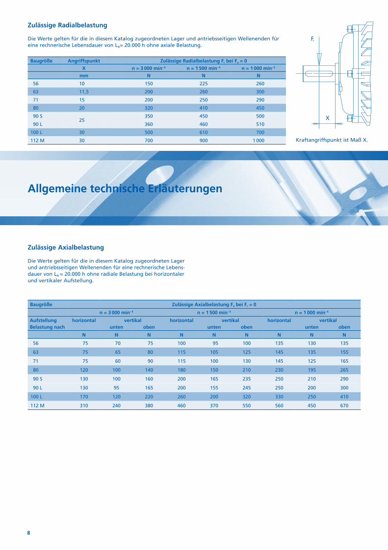
Zulässige Radialbelastung
Die Werte gelten für die in diesem Katalog zugeordneten Lager und antriebsseitigen Wellenenden für eine rechnerische Lebensdauer von Lh= 20.000 h ohne axiale Belastung.
Baugröße Angriffspunkt Zulässige Radialbelastung Fr bei Fa = 0
X n = 3 000 min−1 n = 1 500 min−1 n = 1 000 min−1
mm N N N
56 10 150 225 260
63 11,5 200 260 300
71 15 200 250 290
80 20 320 410 450
90 S25
350 450 500
90 L 360 460 510
100 L 30 500 610 700
112 M 30 700 900 1 000
Baugröße Zulässige Axialbelastung Fa bei Fr = 0
n = 3 000 min−1 n = 1 500 min−1 n = 1 000 min−1
Aufstellung horizontal vertikal horizontal vertikal horizontal vertikalBelastung nach unten oben unten oben unten oben
N N N N N N N N N
56 75 70 75 100 95 100 135 130 135
63 75 65 80 115 105 125 145 135 155
71 75 60 90 115 100 130 145 125 165
80 120 100 140 180 150 210 230 195 265
90 S 130 100 160 200 165 235 250 210 290
90 L 130 95 165 200 155 245 250 200 300
100 L 170 120 220 260 200 320 330 250 410
112 M 310 240 380 460 370 550 560 450 670
Zulässige Axialbelastung
Die Werte gelten für die in diesem Katalog zugeord neten Lager und antriebsseitigen Wellenenden für eine rechnerische Lebens-dauer von Lh = 20.000 h ohne radiale Belastung bei horizontaler und vertikaler Aufstellung.
Fr
X
Kraftangriffspunkt ist Maß X.
9
General technical information
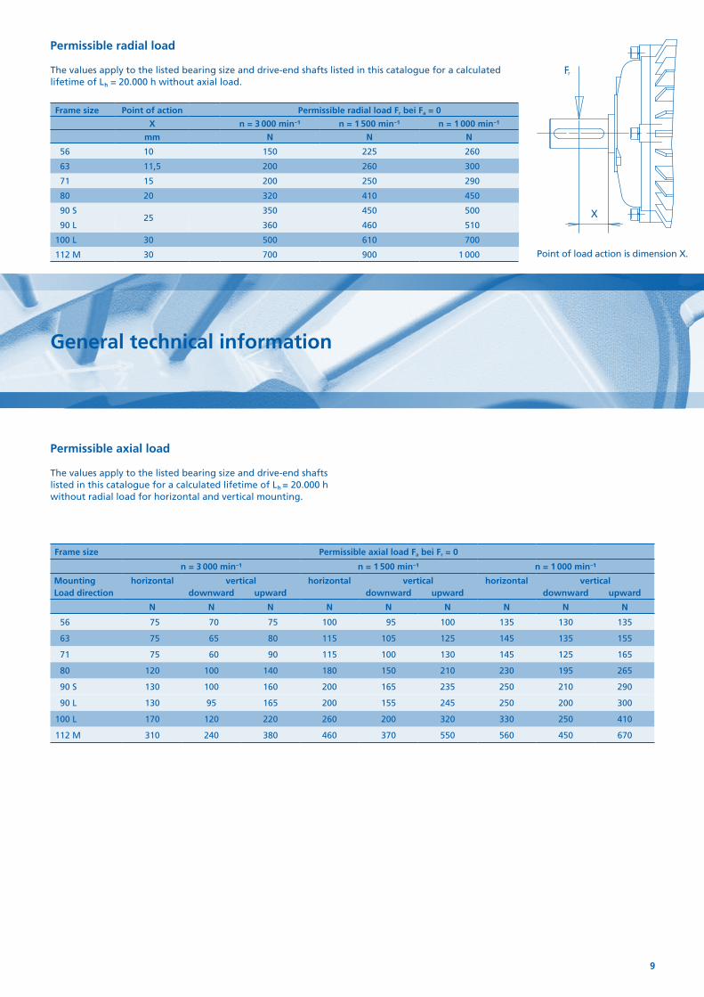
Permissible radial load
The values apply to the listed bearing size and drive-end shafts listed in this catalogue for a calculated lifetime of Lh = 20.000 h without axial load.
Frame size Point of action Permissible radial load Fr bei Fa = 0
X n = 3 000 min−1 n = 1 500 min−1 n = 1 000 min−1
mm N N N
56 10 150 225 260
63 11,5 200 260 300
71 15 200 250 290
80 20 320 410 450
90 S25
350 450 500
90 L 360 460 510
100 L 30 500 610 700
112 M 30 700 900 1 000
Frame size Permissible axial load Fa bei Fr = 0
n = 3 000 min−1 n = 1 500 min−1 n = 1 000 min−1
Mounting horizontal vertical horizontal vertical horizontal verticalLoad direction downward upward downward upward downward upward
N N N N N N N N N
56 75 70 75 100 95 100 135 130 135
63 75 65 80 115 105 125 145 135 155
71 75 60 90 115 100 130 145 125 165
80 120 100 140 180 150 210 230 195 265
90 S 130 100 160 200 165 235 250 210 290
90 L 130 95 165 200 155 245 250 200 300
100 L 170 120 220 260 200 320 330 250 410
112 M 310 240 380 460 370 550 560 450 670
Permissible axial load
The values apply to the listed bearing size and drive-end shafts listed in this catalogue for a calculated lifetime of Lh = 20.000 h without radial load for horizontal and vertical mounting.
Fr
X
Point of load action is dimension X.
10
Allgemeine technische Erläuterungen
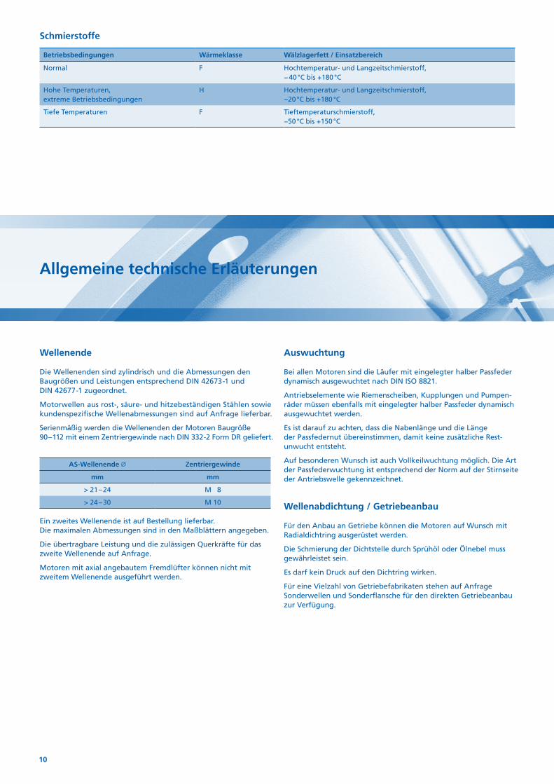
Schmierstoffe
Betriebs bedingungen Wärmeklasse Wälzlagerfett / Einsatzbereich
Normal F Hochtemperatur- und Langzeitschmierstoff, − 40 °C bis +180 °C
Hohe Temperaturen, extreme Betriebs bedingungen
H Hochtemperatur- und Langzeitschmierstoff, −20 °C bis +180 °C
Tiefe Temperaturen F Tieftemperaturschmierstoff, −50 °C bis +150 °C
Wellenende
Die Wellenenden sind zylindrisch und die Abmessungen den Baugrößen und Leistungen entsprechend DIN 42673-1 und DIN 42677-1 zugeordnet.
Motorwellen aus rost-, säure- und hitzebeständigen Stählen sowie kundenspezifische Wellenabmessungen sind auf Anfrage lieferbar.
Serienmäßig werden die Wellenenden der Motoren Baugröße 90 – 112 mit einem Zentriergewinde nach DIN 332-2 Form DR geliefert.
AS-Wellenende Zentriergewinde
mm mm
> 21 – 24 M 8
> 24 – 30 M 10
Ein zweites Wellenende ist auf Bestellung lieferbar. Die maximalen Abmessungen sind in den Maßblättern angegeben.
Die übertragbare Leistung und die zulässigen Querkräfte für das zweite Wellenende auf Anfrage.
Motoren mit axial angebautem Fremdlüfter können nicht mit zweitem Wellenende ausgeführt werden.
Auswuchtung
Bei allen Motoren sind die Läufer mit eingelegter halber Passfeder dynamisch ausgewuchtet nach DIN ISO 8821.
Antriebselemente wie Riemenscheiben, Kupplungen und Pumpen-räder müssen ebenfalls mit eingelegter halber Passfeder dynamisch ausgewuchtet werden.
Es ist darauf zu achten, dass die Nabenlänge und die Länge der Passfedernut übereinstimmen, damit keine zusätzliche Rest-unwucht entsteht.
Auf besonderen Wunsch ist auch Vollkeilwuchtung möglich. Die Art der Passfederwuchtung ist entsprechend der Norm auf der Stirnseite der Antriebswelle gekennzeichnet.
Wellenabdichtung / Getriebeanbau
Für den Anbau an Getriebe können die Motoren auf Wunsch mit Radialdichtring ausgerüstet werden.
Die Schmierung der Dichtstelle durch Sprühöl oder Ölnebel muss gewährleistet sein.
Es darf kein Druck auf den Dichtring wirken.
Für eine Vielzahl von Getriebefabrikaten stehen auf Anfrage Sonderwellen und Sonderflansche für den direkten Getriebeanbau zur Verfügung.
11
General technical information
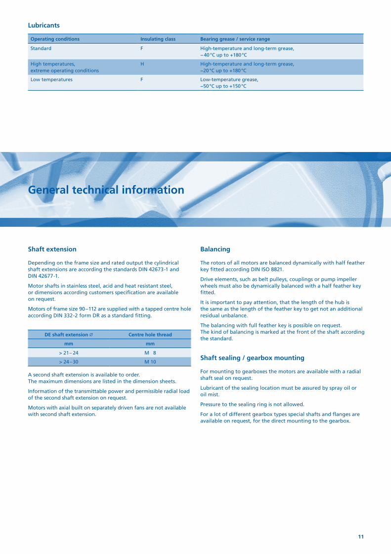
Shaft extension
Depending on the frame size and rated output the cylindrical shaft extensions are according the standards DIN 42673-1 and DIN 42677-1.
Motor shafts in stainless steel, acid and heat resistant steel, or dimensions according customers specification are available on request.
Motors of frame size 90 – 112 are supplied with a tapped centre hole according DIN 332-2 form DR as a standard fitting.
DE shaft extension Centre hole thread
mm mm
> 21 – 24 M 8
> 24 – 30 M 10
A second shaft extension is available to order. The maximum dimensions are listed in the dimension sheets.
Information of the transmittable power and permissible radial load of the second shaft extension on request.
Motors with axial built on separately driven fans are not available with second shaft extension.
Balancing
The rotors of all motors are balanced dynamically with half feather key fitted according DIN ISO 8821.
Drive elements, such as belt pulleys, couplings or pump impeller wheels must also be dynamically balanced with a half feather key fitted.
It is important to pay attention, that the length of the hub is the same as the length of the feather key to get not an additional residual unbalance.
The balancing with full feather key is possible on request. The kind of balancing is marked at the front of the shaft according the standard.
Shaft sealing / gearbox mounting
For mounting to gearboxes the motors are available with a radial shaft seal on request.
Lubricant of the sealing location must be assured by spray oil or oil mist.
Pressure to the sealing ring is not allowed.
For a lot of different gearbox types special shafts and flanges are available on request, for the direct mounting to the gearbox.
Lubricants
Operating conditions Insulating class Bearing grease / service range
Standard F High-temperature and long-term grease, − 40 °C up to +180 °C
High temperatures, extreme operating conditions
H High-temperature and long-term grease, −20 °C up to +180 °C
Low temperatures F Low-temperature grease, −50 °C up to +150 °C
12
Allgemeine technische Erläuterungen
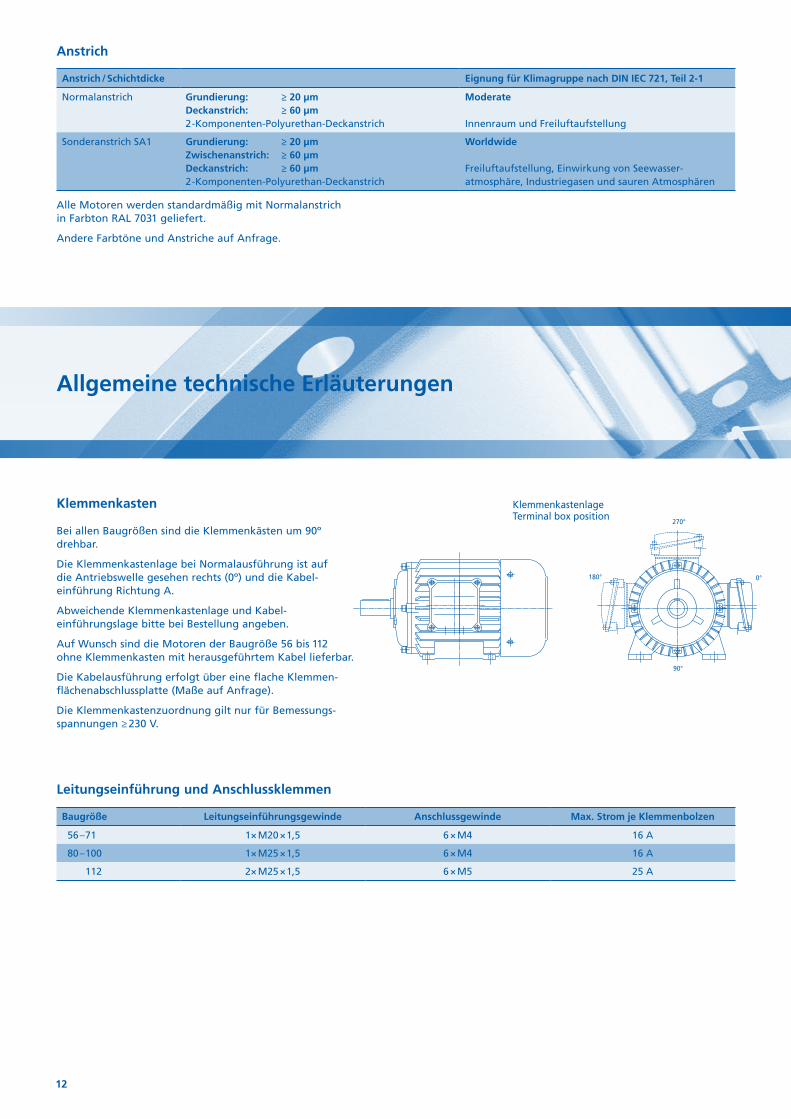
Klemmenkasten
Bei allen Baugrößen sind die Klemmenkästen um 90º drehbar.
Die Klemmenkastenlage bei Normalausführung ist auf die Antriebswelle gesehen rechts (0º) und die Kabel-einführung Richtung A.
Abweichende Klemmenkastenlage und Kabel-einführungslage bitte bei Bestellung angeben.
Auf Wunsch sind die Motoren der Baugröße 56 bis 112 ohne Klemmenkasten mit herausgeführtem Kabel lieferbar.
Die Kabelausführung erfolgt über eine flache Klemmen-flächen abschlussplatte (Maße auf Anfrage).
Die Klemmenkastenzuordnung gilt nur für Bemessungs-spannungen ≥ 230 V.
90°
0°
270°
180°
KlemmenkastenlageTerminal box position
Leitungseinführung und Anschlussklemmen
Baugröße Leitungseinführungsgewinde Anschlussgewinde Max. Strom je Klemmenbolzen
56 – 71 1× M20 × 1,5 6 × M4 16 A
80 – 100 1× M25 × 1,5 6 × M4 16 A
112 2× M25 × 1,5 6 × M5 25 A
Alle Motoren werden standardmäßig mit Normalanstrich in Farbton RAL 7031 geliefert.
Andere Farbtöne und Anstriche auf Anfrage.
Anstrich
Anstrich / Schichtdicke Eignung für Klimagruppe nach DIN IEC 721, Teil 2-1
Normalanstrich Grundierung: ≥ 20 µmDeckanstrich: ≥ 60 µm 2-Komponenten-Polyurethan-Deckanstrich
Moderate Innenraum und Freiluftaufstellung
Sonderanstrich SA1 Grundierung: ≥ 20 µmZwischenanstrich: ≥ 60 µmDeckanstrich: ≥ 60 µm 2-Komponenten-Polyurethan-Deckanstrich
Worldwide Freiluftaufstellung, Einwirkung von Seewasser-atmosphäre, Industriegasen und sauren Atmosphären
13
General technical information
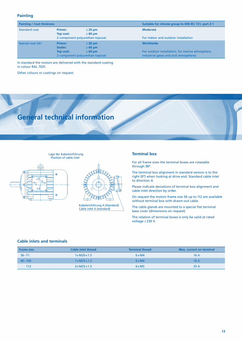
Terminal box
For all frame sizes the terminal boxes are rotatable through 90º.
The terminal box alignment in standard version is to the right (0º) when looking at drive end. Standard cable inlet to direction A.
Please indicate deviations of terminal box alignment and cable inlet direction by order.
On request the motors frame size 56 up to 112 are available without terminal box with drawn-out cable.
The cable glands are mounted to a special flat terminal base cover (dimensions on request)
The relation of terminal boxes is only be valid at rated voltage ≥ 230 V.
A
DC
B
Lage der KabeleinführungPosition of cable inlet
Kabeleinführung A (Standard)Cable inlet A (standard)
Cable inlets and terminals
Frame size Cable inlet thread Terminal thread Max. current on terminal
56 – 71 1× M20 × 1.5 6 × M4 16 A
80 – 100 1× M25 × 1.5 6 × M4 16 A
112 2× M25 × 1.5 6 × M5 25 A
In standard the motors are delivered with the standard coating in colour RAL 7031.
Other colours or coatings on request.
Painting
Painting / Coat thickness Suitable for climate group to DIN IEC 721, part 2-1
Standard coat Primer: ≥ 20 µmTop coat: ≥ 60 µm 2-component polyurethan topcoat
Moderate For indoor and outdoor installation
Special coat SA1 Primer: ≥ 20 µmSealer: ≥ 60 µmTop coat: ≥ 60 µm 2-component polyurethan topcoat
Worldwide For outdoor installation, for marine atmosphere, industrial gases and acid atmospheres
14
Allgemeine technische Erläuterungen
Elektrische Ausführung
Die in den Auswahltabellen angegebenen Bemessungsleistungen und Betriebswerte gelten für die Betriebsart S1 nach DIN EN 60034-1 bei einer Bemessungsfrequenz von 50 Hz, einer Kühlmitteltemperatur von max. 40 °C und einer Aufstellungshöhe bis 1 000 m über NN.
Die Betriebsdaten gelten mit den Toleranzen nach DIN EN 60034-1 für die angegebene Bemessungsspannung.
Motor-Typ
Die Einphasenmotoren sind, bedingt durch unterschiedliche Anlaufmomente, den jeweiligen Betriebsverhältnissen anzupassen.
• EHBEinphasenmotoren mit Arbeits- und Hilfswicklung, mit Betriebs-kondensator. Für Leicht bzw. Leeranlauf.
MA / MN ca. 0,3 – 0,7
• EAZREinphasenmotoren mit Arbeits- und Hilfswicklung, mit Betriebs- und Anlaufkondensator.
Anlaufkondensator wird nach erfolgtem Hochlauf durch ein zeitabhängiges Relais abgeschaltet. Anlaufzeit ist einstellbar.
MA / MN ca. 1,5 – 2,0
Motorschutz
Bei stromabhängigem Motorschutz muss der Schutzschalter auf den am Leistungsschild angegebenen Nennstrom eingestellt werden.
Bei Schalthäufigkeit, Kurzzeitbetrieb, Kühlmittelausfall oder großen Temperaturschwankungen ist der Motorschutz nur mit direkter Temperaturüberwachung sicher wirksam. Hierzu bieten sich auf Wunsch folgende Möglichkeiten an:
• Temperaturschalter als Öffner
Bei Erreichen der Grenztemperatur öffnet dieser selbsttätig den Hilfsstromkreis und schaltet erst nach wesentlicher Temperatur-änderung wieder ein. Schaltleistung: bei Wechselspannung 250 V 1,6 A.
• Kaltleiterschutz
Die eingebauten Kaltleiter werden in Verbindung mit einem Auslösegerät betrieben. Bei Erreichen der Grenztemperatur ändert der Kaltleiterfühler sprunghaft seinen Widerstand. In Verbindung mit dem Auslösegerät wird diese Wirkung zur Überwachung der Motortemperatur ausgenutzt. Das im Gerät eingebaute Relais verfügt über einen Umschaltkontakt, dessen Öffner und Schließer für die Steuerung benutzt werden können. Vorteil: Schutzeinrichtung überwacht sich selbst; geringe Schalt-toleranz; schnelles Wiedereinschalten des Antriebes.
• Messung der Wicklungs- oder Lagertemperatur
Durch den Einbau von Platin-Temperaturfühlern PT 100 oder PT 1000 sind die Temperaturen in der Motorwicklung oder an der Lagerung direkt messbar.
Die Anschlüsse der Temperaturüberwachung sind standardmäßig auf eine Klemmenleiste im Hauptklemmenkasten geführt.
Auf Wunsch kann ein separater Klemmenkasten für die Zusatz-einrichtungen angebracht werden.
Kondensatoren
Betriebskondensatoren sind hochwertige Folien-Kondensatoren. Anlaufkondensatoren sind Elektrolytkondensatoren.
Spannung und Frequenz
230 V 50 Hz Einphasennetz.
Andere Spannungen und Frequenzen sind gegen Mehrpreis lieferbar. Die Maßblätter haben Gültigkeit für 230 V 50 Hz.
Jede Spannungs- bzw. Frequenzänderung kann eine Änderung der Kondensatoren und damit des Maßblattes zur Folge haben.
Ständerwicklung
In der Normalausführung sind die Motoren in Wärmeklasse „F“ ausgeführt. Die Isolierung der Motoren ist tropenfest. Verstärkter Tropen- und Feuchtschutz ist gegen Mehrpreis lieferbar.
Für erhöhte Kühlmitteltemperaturen* oder Wärmebeanspruchung ist ein Isolationssystem der Wärmeklasse „H“ lieferbar.
* ggf. werden die Kondensatoren lose mit geliefert.
15
General technical information
Electrical design
The rated output and data listed in this catalogue apply to continuous operating S1 according to DIN EN 60034-1 at rated frequency 50 Hz, at an ambient temperature of 40 °C and at a site altitude from up to 1 000 m above sea level.
The rated data with the tolerances according to DIN EN 60034-1 apply to the listed rated voltage.
Motor-Type
Depending on their different starting torques single phase motors are to be adapt to the working conditions.
• EHBSingle phase motor with main and auxiliary winding, capacitor run. Light or no load starting.
MA / MN ca. 0.3 – 0.7
• EAZRSingle phase motor with main and auxiliary winding, capacitor start and capacitor run.
Starting capacitor is cut off by a time operated relay. Startup time is adjustable.
MA / MN ca. 1.5 – 2.0
Capacitors
Running capacitor are high-quality sheet capacitor. Starting capacitor are electrolytic capacitor.
Voltage and frequency
230 V 50 Hz.
Other voltages and frequency are avail able at extra price. The dimension sheets are designed for 230 V 50 Hz.
Every variation in voltage or frequency may cause the variation of the capacitor and the dimension sheet.
Stator winding
In standard version the winding is designed in insulating class “F”. The insulating of the motors is tropic-proof. Increased tropic- and moisture-proof insulating is available at extra price.
An isolation system of insulating class “H“ is available for increased ambient temperature *.
* if necessary the capacitors will be delivered loosen.
Motor protection
For current-sensitive motor protection, the protective switch has to be set to the rated current given on the name plate.
This motor protection is inadequate for high number of opera-tions, short-time operation, coolant breakdown or for fluctuations in coolant temperature. In this case motors should be protected by direct temperature protection (extra price):
• Thermal protector switch
When reaching the limiting temperature, the switch opens the control circuit. The NC-switch closes the circuit when the temper-ature decreases essential. Contact rating: 1.6 Amps for 250 VAC.
• Thermistor protection
The embedded temperature sensors are able to work only in conjunction with a tripping unit. When reaching the limiting temperature, the thermistor changes its resistance almost instan-taneously. This action is utilized in conjunction with the tripping unit to monitor motor temperature. The relay incorporated in the device has a change-over contact, in which the contacts can be used for the control system. Advantages: the protection system is self-monitoring; low switching tolerance; quick reconnection of the drive.
• Measuring of winding or bearing temperatures
The temperature of the motor winding or bearings can be directly measured by incorporated temperature sensors PT 100 or PT 1000.
In standard the connection of the temperature protection is with a terminal block inside the main terminal box.
On request the connection in a separate mounted terminal box is possible.
16
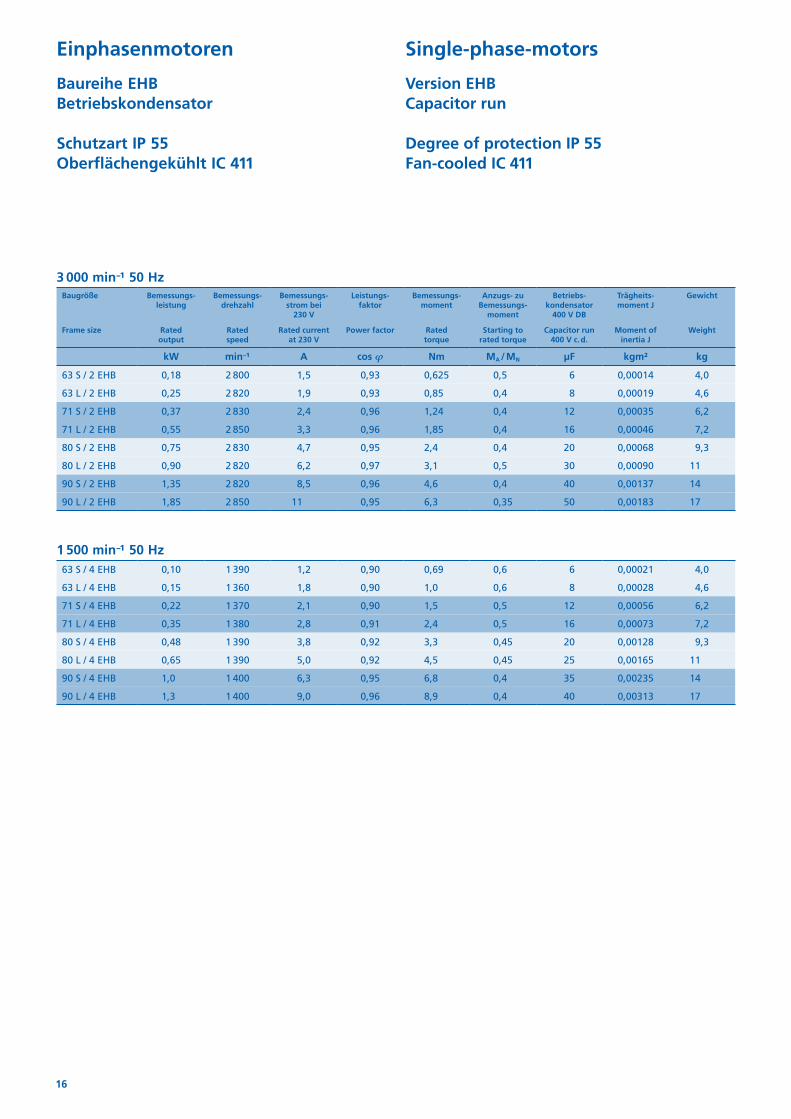
Einphasenmotoren
Baureihe EHB Betriebskondensator
Schutzart IP 55 Oberflächengekühlt IC 411
Single-phase-motors
Version EHB Capacitor run
Degree of protection IP 55 Fan-cooled IC 411
3 000 min−1 50 Hz Baugröße Bemessungs-
leistungBemessungs-
drehzahlBemessungs-
strom bei 230 V
Leistungs-faktor
Bemessungs-moment
Anzugs- zu Bemessungs-
moment
Betriebs-kondensator
400 V DB
Trägheits -moment J
Gewicht
Frame size Rated output
Rated speed
Rated current at 230 V
Power factor Rated torque
Starting to rated torque
Capacitor run 400 V c. d.
Moment of inertia J
Weight
kW min−¹ A cos 𝝋 Nm MA / MN μF kgm² kg
63 S / 2 EHB 0,18 2 800 1,5 0,93 0,625 0,5 6 0,00014 4,0
63 L / 2 EHB 0,25 2 820 1,9 0,93 0,85 0,4 8 0,00019 4,6
71 S / 2 EHB 0,37 2 830 2,4 0,96 1,24 0,4 12 0,00035 6,2
71 L / 2 EHB 0,55 2 850 3,3 0,96 1,85 0,4 16 0,00046 7,2
80 S / 2 EHB 0,75 2 830 4,7 0,95 2,4 0,4 20 0,00068 9,3
80 L / 2 EHB 0,90 2 820 6,2 0,97 3,1 0,5 30 0,00090 11
90 S / 2 EHB 1,35 2 820 8,5 0,96 4,6 0,4 40 0,00137 14
90 L / 2 EHB 1,85 2 850 11 0,95 6,3 0,35 50 0,00183 17
1 500 min−1 50 Hz63 S / 4 EHB 0,10 1 390 1,2 0,90 0,69 0,6 6 0,00021 4,0
63 L / 4 EHB 0,15 1 360 1,8 0,90 1,0 0,6 8 0,00028 4,6
71 S / 4 EHB 0,22 1 370 2,1 0,90 1,5 0,5 12 0,00056 6,2
71 L / 4 EHB 0,35 1 380 2,8 0,91 2,4 0,5 16 0,00073 7,2
80 S / 4 EHB 0,48 1 390 3,8 0,92 3,3 0,45 20 0,00128 9,3
80 L / 4 EHB 0,65 1 390 5,0 0,92 4,5 0,45 25 0,00165 11
90 S / 4 EHB 1,0 1 400 6,3 0,95 6,8 0,4 35 0,00235 14
90 L / 4 EHB 1,3 1 400 9,0 0,96 8,9 0,4 40 0,00313 17
17
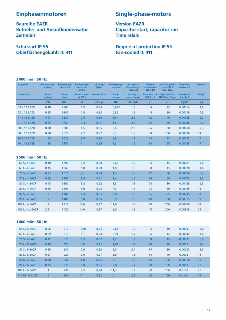
Einphasenmotoren
Baureihe EAZR Betriebs- und Anlaufkondensator Zeitrelais
Schutzart IP 55 Oberflächengekühlt IC 411
Single-phase-motors
Version EAZR Capacitor start, capacitor run Time relais
Degree of protection IP 55 Fan-cooled IC 411
3 000 min−1 50 Hz Baugröße Bemessungs-
leistungBemessungs-
drehzahlBemessungs-
strom bei 230 V
Leistungs-faktor
Bemessungs-moment
Anzugs- zu Bemessungs-
moment
Betriebs-kondensator
400 V DB
Anlaufkonden-sator 280 V max. 3sec.
Trägheits -moment J
Gewicht
Frame size Rated output
Rated speed
Rated current at 230 V
Power factor Rated torque
Starting to rated torque
Capacitor run 400 V c. d.
Capacitor start 280 V max 3 sec.
Moment of inertia J
Weight
kW min−¹ A cos 𝝋 Nm MA / MN μF μF kgm² kg
63 S / 2 EAZR 0,18 2 800 1,5 0,93 0,625 1,8 6 25 0,00014 4,0
63 L / 2 EAZR 0,25 2 800 1,9 0,93 0,85 1,8 8 30 0,00019 4,6
71 S / 2 EAZR 0,37 2 830 2,4 0,96 1,0 2,2 12 40 0,00035 6,2
71 L / 2 EAZR 0,55 2 850 3,3 0,91 1,5 2,2 16 40 0,00046 7,2
80 S / 2 EAZR 0,70 2 800 4,5 0,95 2,4 2,0 25 80 0,00068 9,3
80 L / 2 EAZR 0,90 2 820 6,2 0,97 3,1 1,9 30 100 0,00090 11
90 S / 2 EAZR 1,35 2 820 8,5 0,90 4,6 1,7 40 125 0,00137 14
90 L / 2 EAZR 1,85 2 850 11 0,96 6,3 1,5 50 125 0,00183 17
1 500 min−1 50 Hz 63 S / 4 EAZR 0,10 1 390 1,2 0,90 0,69 1,9 6 15 0,00021 4,0
63 L / 4 EAZR 0,15 1 360 1,8 0,90 1,0 1,8 8 15 0,00028 4,6
71 S / 4 EAZR 0,22 1 370 2,1 0,90 1,5 1,8 12 30 0,00056 6,2
71 L / 4 EAZR 0,35 1 360 2,8 0,91 2,4 1,6 16 50 0,00073 7,2
80 S / 4 EAZR 0,48 1 390 3,8 0,92 3,3 1,6 20 80 0,00128 9,3
80 L / 4 EAZR 0,65 1 390 5,0 0,92 4,5 1,6 25 80 0,00165 11
90 S / 4 EAZR 1,0 1 400 6,3 0,95 6,8 1,5 35 125 0,00235 14
90 L / 4 EAZR 1,3 1 400 9,0 0,96 8,9 1,5 40 160 0,00313 17
100 L / 4 EAZR 1,8 1 410 11,0 0,97 12,0 1,5 40 200 0,00450 22
100 L / 4 a EAZR 2,2 1 420 14,0 0,97 15,0 1,5 45 200 0,00600 25
1 000 min−1 50 Hz
63 S / 6 EAZR 0,06 910 0,95 0,95 0,63 1,7 5 10 0,00031 4,0
63 L / 6 EAZR 0,09 910 1,1 0,94 0,94 1,7 6 12 0,00042 4,6
71 S / 6 EAZR 0,12 920 1,3 0,92 1,25 1,7 8 15 0,00091 6,2
71 L / 6 EAZR 0,18 920 1,8 0,92 1,87 1,7 10 20 0,0012 7,2
80 S / 6 EAZR 0,25 930 2,0 0,92 2,5 2,0 10 30 0,00022 9,3
80 L / 6 EAZR 0,37 930 3,0 0,97 3,8 1,8 14 40 0,0028 11
90 S / 6 EAZR 0,50 930 4,0 0,85 5,1 1,9 14 60 0,00370 14
90 L / 6 EAZR 0,75 920 5,0 0,95 7,8 1,7 20 100 0,0050 17
100 L / 6 EAZR 1,1 930 7,5 0,94 11,3 1,8 30 160 0,0100 25
112 M / 6 EAZR 1,5 950 11 0,92 15 2,2 50 160 0,0180 31
18
u
d
s4
w1
l
q
k1/k1B
l1
u1
sb
c
g
0°
270°
180°
h
rr
r
f
d1 t 1
p
s5
k /kB
a w2/w2BOption Klemmenkasten oben (270°)option terminal-box on top (270°)
Option Klemmenkasten links (180°)option terminal-box left (180°)
e
t
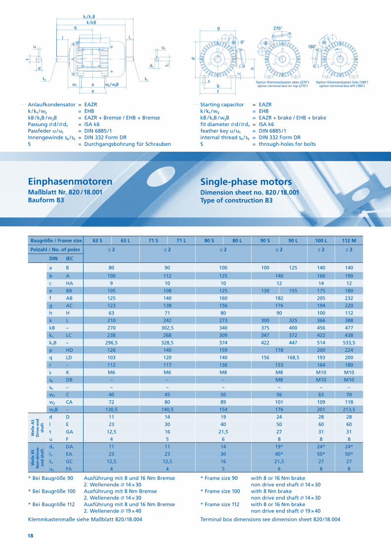
Einphasenmotoren Maßblatt Nr. 820 / 18.001 Bauform B3
Single-phase motorsDimension sheet no. 820 / 18.001 Type of construction B3
Baugröße / Frame size 63 S 63 L 71 S 71 L 80 S 80 L 90 S 90 L 100 L 112 M
Polzahl / No. of poles ≥ 2 ≥ 2 ≥ 2 ≥ 2 ≥ 2 ≥ 2
DIN IEC
a B 80 90 100 100 125 140 140
b A 100 112 125 140 160 190
c HA 9 10 10 12 14 12
e BB 105 108 125 130 155 175 180
f AB 125 140 160 182 205 232
g AC 123 138 156 176 194 220
h H 63 71 80 90 100 112
k L 210 242 273 300 325 366 388
kB – 270 302,5 340 375 400 456 477
k1 LC 238 268 309 347 372 422 438
k1B – 296,5 328,5 374 422 447 514 533,5
p HD 126 140 159 178 200 224
q LD 103 120 140 156 168,5 193 200
r – 112 117 136 153 164 180
s K M6 M6 M8 M8 M10 M10
s4 DB – – – M8 M10 M10
s5 – – – – – – –
w1 C 40 45 50 56 63 70
w2 CA 72 80 89 101 109 118
w2B – 130,5 140,5 154 176 201 213,5
Wel
le A
S D
rive
-en
d
shaf
t
d D 11 14 19 24 28 28
l E 23 30 40 50 60 60
t GA 12,5 16 21,5 27 31 31
u F 4 5 6 8 8 8
Wel
le B
SN
on
-dri
vve-
en
d s
haf
t d1 DA 11 11 14 19* 24* 24*
l1 EA 23 23 30 40* 50* 50*
t1 GC 12,5 12,5 16 21,5 27 27
u1 FA 4 4 5 6 8 8
Anlaufkondensator = EAZR k / k1 / w2 = EHB kB / k1B / w2B = EAZR + Bremse / EHB + Bremse Passung d / d1 = ISA k6 Passfeder u / u1 = DIN 6885 / 1 Innengewinde s4 / s5 = DIN 332 Form DR S = Durchgangsbohrung für Schrauben
Starting capacitor = EAZR k / k1 / w2 = EHB kB / k1B / w2B = EAZR + brake / EHB + brake fit diameter d / d1 = ISA k6 feather key u / u1 = DIN 6885 / 1 internal thread s4 / s5 = DIN 332 Form DR S = through-holes for bolts
* Bei Baugröße 90 Ausführung mit 8 und 16 Nm Bremse 2. Wellenende 14 × 30
* Bei Baugröße 100 Ausführung mit 8 Nm Bremse 2. Wellenende 14 × 30
* Bei Baugröße 112 Ausführung mit 8 und 16 Nm Bremse 2. Wellenende 19 × 40
Klemmkastenmaße siehe Maßblatt 820 / 18.004
* Frame size 90 with 8 or 16 Nm brake non drive end shaft 14 × 30
* Frame size 100 with 8 Nm brake non drive end shaft 14 × 30
* Frame size 112 with 8 or 16 Nm brake non drive end shaft 19 × 40
Terminal box dimensions see dimension sheet 820 / 18.004
19
s4
d
t
u l
a 1 b 1
i2 c1
s5
d1
u1
s2
4x90°
45°
g
e1
r
l1
k1/k1B
k/kBq
f1
t 1
s4
d
t
u l
a 1 b 1i2 c1
s5
d1
u1
s2
4x90°
45°
g
e1
r
l1
k1/k1B
k/kBq
f1
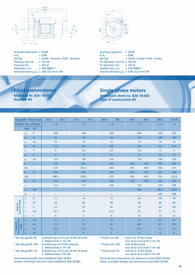
t 1Einphasenmotoren Maßblatt Nr. 820 / 18.002 Bauform B5
Single-phase motorsDimension sheet no. 820 / 18.002 Type of construction B5
Baugröße / Frame size 63 S 63 L 71 S 71 L 80 S 80 L 90 S 90 L 100 L 112 M
Polzahl / No. of poles ≥ 2 ≥ 2 ≥ 2 ≥ 2 ≥ 2 ≥ 2
DIN IEC
a1 P 140 160 200 200 250 250
b1 N 95 110 130 130 180 180
c1 LA 10 10 12 12 16 16
e1 M 115 130 165 165 215 215
f1 T 3 3,5 3,5 3,5 4 4
s2 S 9 9 11 11 14 14
g AC 123 138 156 176 194 220
k L 210 242 273 300 325 366 382
kB – 270 302,5 340 375 400 456 477
k1 LC 238 268 309 347 372 422 438
k1B – 296,5 328,5 374 422 447 514 533,5
q LD 103 120 140 156 168,5 193 200
r – 112 117 136 153 164 180
s4 DB – – – M 8 M10 M10
s5 – – – – – M 8 M 8
Wel
le A
S D
rive
-en
d s
haf
t
d D 11 14 19 24 28 28
i2 LE 23 30 40 50 60 60
l E 23 30 40 50 60 60
t GA 12,5 16 21,5 27 31 31
u F 4 5 6 8 8 8
Wel
le B
SN
on
-dri
vve-
end
sh
aft
d1 DA 11 11 14 19* 24* 24*
l1 EA 23 23 30 40* 50* 50*
t1 GC 12,5 12,5 16 21,5 27 27
u1 FA 4 4 5 6 8 8
Anlaufkondensator = EAZR k / k1 = EHB kB / k1B = EAZR + Bremse / EHB + Bremse Passung d / d1 = ISA k6 Passung b1 = ISA j6 Passfeder u / u1 = DIN 6885 / 1 Innengewinde s4 / s5 = DIN 332 Form DR
Starting capacitor = EAZR k / k1 = EHB kB / k1B = EAZR + brake / EHB + brake fit diameter d / d1 = ISA k6 fit diameter b1 = ISA j6 feather key u / u1 = DIN 6885 / 1 internal thread s4 / s5 = DIN 332 Form DR
* Bei Baugröße 90 Ausführung mit 8 und 16 Nm Bremse 2. Wellenende 14 × 30
* Bei Baugröße 100 Ausführung mit 8 Nm Bremse 2. Wellenende 14 × 30
* Bei Baugröße 112 Ausführung mit 8 und 16 Nm Bremse 2. Wellenende 19 × 40
Klemmkastenmaße siehe Maßblatt 820 / 18.004 Andere lieferbare Flansche siehe Maßblatt 820 / 18.005
* Frame size 90 with 8 or 16 Nm brake non drive end shaft 14 × 30
* Frame size 100 with 8 Nm brake non drive end shaft 14 × 30
* Frame size 112 with 8 or 16 Nm brake non drive end shaft 19 × 40
Terminal box dimensions see dimension sheet 820 / 18.004 Other available flanges see dimension sheet 820 / 18.005
20
k1/k1B
l1
u1
4x90°
45°
g
r
d1
s2
e1
s5
t 1
k /kBq
c1
u
d
s4 f1
i2
b 1a 1t
l
k1/k1B
l1
u1
4x90°
45°
g
r
d1
s2
e1
s5
t 1
k /kBq
c1
u
d
s4 f1
i2
b 1a 1t
l
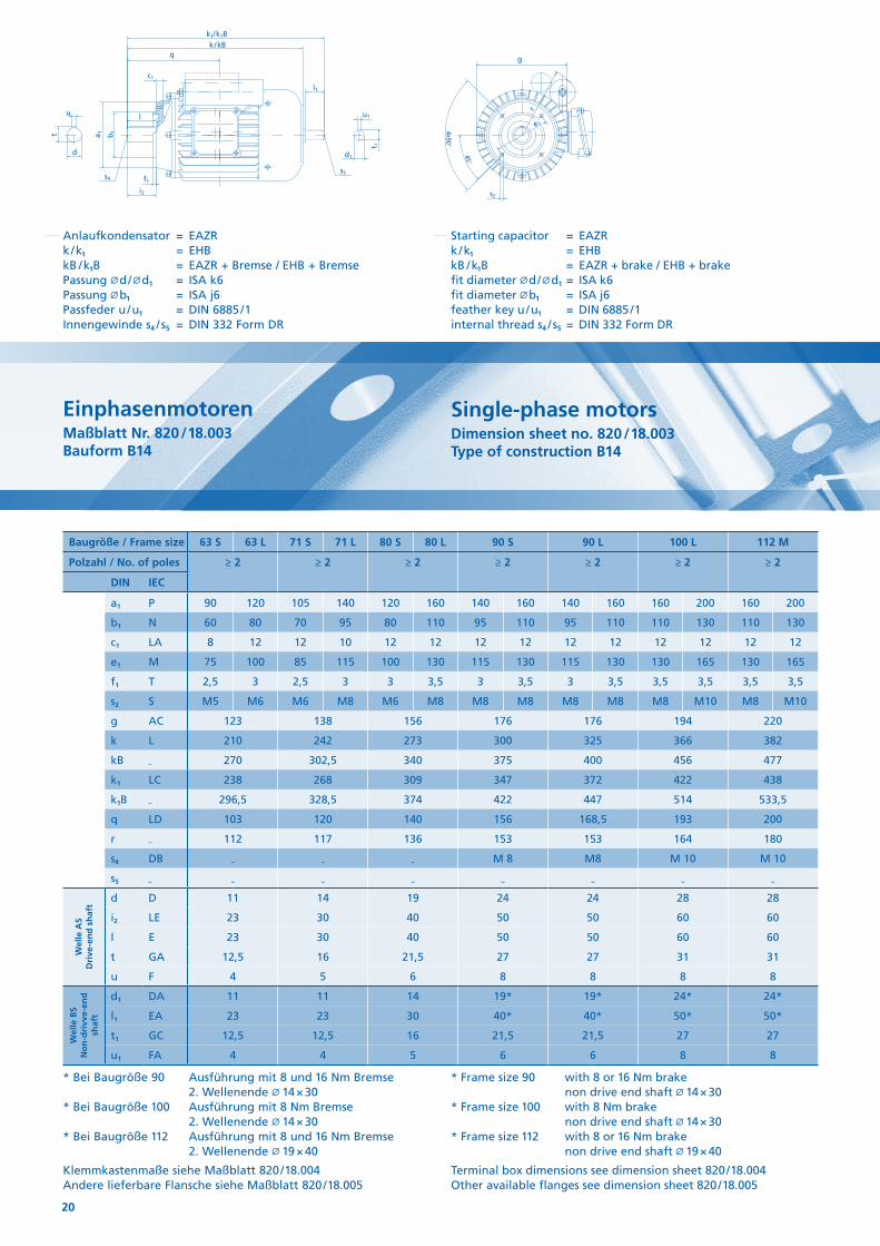
Einphasenmotoren Maßblatt Nr. 820 / 18.003 Bauform B14
Single-phase motorsDimension sheet no. 820 / 18.003 Type of construction B14
Baugröße / Frame size 63 S 63 L 71 S 71 L 80 S 80 L 90 S 90 L 100 L 112 M
Polzahl / No. of poles ≥ 2 ≥ 2 ≥ 2 ≥ 2 ≥ 2 ≥ 2 ≥ 2
DIN IEC
a1 P 90 120 105 140 120 160 140 160 140 160 160 200 160 200
b1 N 60 80 70 95 80 110 95 110 95 110 110 130 110 130
c1 LA 8 12 12 10 12 12 12 12 12 12 12 12 12 12
e1 M 75 100 85 115 100 130 115 130 115 130 130 165 130 165
f1 T 2,5 3 2,5 3 3 3,5 3 3,5 3 3,5 3,5 3,5 3,5 3,5
s2 S M5 M6 M6 M8 M6 M8 M8 M8 M8 M8 M8 M10 M8 M10
g AC 123 138 156 176 176 194 220
k L 210 242 273 300 325 366 382
kB – 270 302,5 340 375 400 456 477
k1 LC 238 268 309 347 372 422 438
k1B – 296,5 328,5 374 422 447 514 533,5
q LD 103 120 140 156 168,5 193 200
r – 112 117 136 153 153 164 180
s4 DB – – – M 8 M8 M 10 M 10
s5 – – – – – – – –
Wel
le A
S D
rive
-en
d s
haf
t
d D 11 14 19 24 24 28 28
i2 LE 23 30 40 50 50 60 60
l E 23 30 40 50 50 60 60
t GA 12,5 16 21,5 27 27 31 31
u F 4 5 6 8 8 8 8
Wel
le B
SN
on
-dri
vve-
end
sh
aft
d1 DA 11 11 14 19* 19* 24* 24*
l1 EA 23 23 30 40* 40* 50* 50*
t1 GC 12,5 12,5 16 21,5 21,5 27 27
u1 FA 4 4 5 6 6 8 8
Anlaufkondensator = EAZR k / k1 = EHB kB / k1B = EAZR + Bremse / EHB + Bremse Passung d / d1 = ISA k6 Passung b1 = ISA j6 Passfeder u / u1 = DIN 6885 / 1 Innengewinde s4 / s5 = DIN 332 Form DR
Starting capacitor = EAZR k / k1 = EHB kB / k1B = EAZR + brake / EHB + brake fit diameter d / d1 = ISA k6 fit diameter b1 = ISA j6 feather key u / u1 = DIN 6885 / 1 internal thread s4 / s5 = DIN 332 Form DR
* Bei Baugröße 90 Ausführung mit 8 und 16 Nm Bremse 2. Wellenende 14 × 30
* Bei Baugröße 100 Ausführung mit 8 Nm Bremse 2. Wellenende 14 × 30
* Bei Baugröße 112 Ausführung mit 8 und 16 Nm Bremse 2. Wellenende 19 × 40
Klemmkastenmaße siehe Maßblatt 820 / 18.004 Andere lieferbare Flansche siehe Maßblatt 820 / 18.005
* Frame size 90 with 8 or 16 Nm brake non drive end shaft 14 × 30
* Frame size 100 with 8 Nm brake non drive end shaft 14 × 30
* Frame size 112 with 8 or 16 Nm brake non drive end shaft 19 × 40
Terminal box dimensions see dimension sheet 820 / 18.004 Other available flanges see dimension sheet 820 / 18.005
21
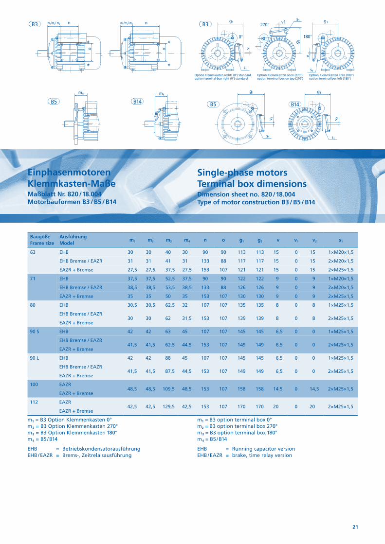
Einphasenmotoren Klemmkasten-Maße Maßblatt Nr. 820 / 18.004 Motorbauformen B3 / B5 / B14
Single-phase motors Terminal box dimensionsDimension sheet no. 820 / 18.004 Type of motor construction B3 / B5 / B14
Baugöße Frame size
Ausführung Model
m1 m2 m3 m4 n o g1 g2 v v1 v2 s1
63 EHB 30 30 40 30 90 90 113 113 15 0 15 1×M20×1,5
EHB Bremse / EAZR 31 31 41 31 133 88 117 117 15 0 15 2×M20×1,5
EAZR + Bremse 27,5 27,5 37,5 27,5 153 107 121 121 15 0 15 2×M25×1,5
71 EHB 37,5 37,5 52,5 37,5 90 90 122 122 9 0 9 1×M20×1,5
EHB Bremse / EAZR 38,5 38,5 53,5 38,5 133 88 126 126 9 0 9 2×M20×1,5
EAZR + Bremse 35 35 50 35 153 107 130 130 9 0 9 2×M25×1,5
80 EHB 30,5 30,5 62,5 32 107 107 135 135 8 0 8 1×M25×1,5
EHB Bremse / EAZR
EAZR + Bremse30 30 62 31,5 153 107 139 139 8 0 8 2×M25×1,5
90 S EHB 42 42 63 45 107 107 145 145 6,5 0 0 1×M25×1,5
EHB Bremse / EAZR
EAZR + Bremse41,5 41,5 62,5 44,5 153 107 149 149 6,5 0 0 2×M25×1,5
90 L EHB 42 42 88 45 107 107 145 145 6,5 0 0 1×M25×1,5
EHB Bremse / EAZR
EAZR + Bremse41,5 41,5 87,5 44,5 153 107 149 149 6,5 0 0 2×M25×1,5
100 EAZR
EAZR + Bremse48,5 48,5 109,5 48,5 153 107 158 158 14,5 0 14,5 2×M25×1,5
112 EAZR
EAZR + Bremse42,5 42,5 129,5 42,5 153 107 170 170 20 0 20 2×M25×1,5
m1 = B3 Option Klemmenkasten 0° m2 = B3 Option Klemmenkasten 270° m3 = B3 Option Klemmenkasten 180° m4 = B5 / B14
EHB = Betriebskondensatorausführung EHB / EAZR = Brems-, Zeitrelaisausführung
m1 = B3 option terminal box 0° m2 = B3 option terminal box 270° m3 = B3 option terminal box 180° m4 = B5 / B14
EHB = Running capacitor version EHB / EAZR = brake, time relay version
g 2
v1
v
o o
g1 g1
g1 g1
0° 180°
270°
v
v 2 v 2
s1 s1
s1
Option Klemmkasten oben (270°)option terminal-box on top (270°)
Option Klemmkasten links (180°)option terminal-box left (180°)
Option Klemmkasten rechts (0°) Standardoption terminal-box right (0°) standard
s1
m4m4
nnm1/m2/ m3 m1/m2/ m3
s1
B5
B3 B3
B5 B14 B14
22
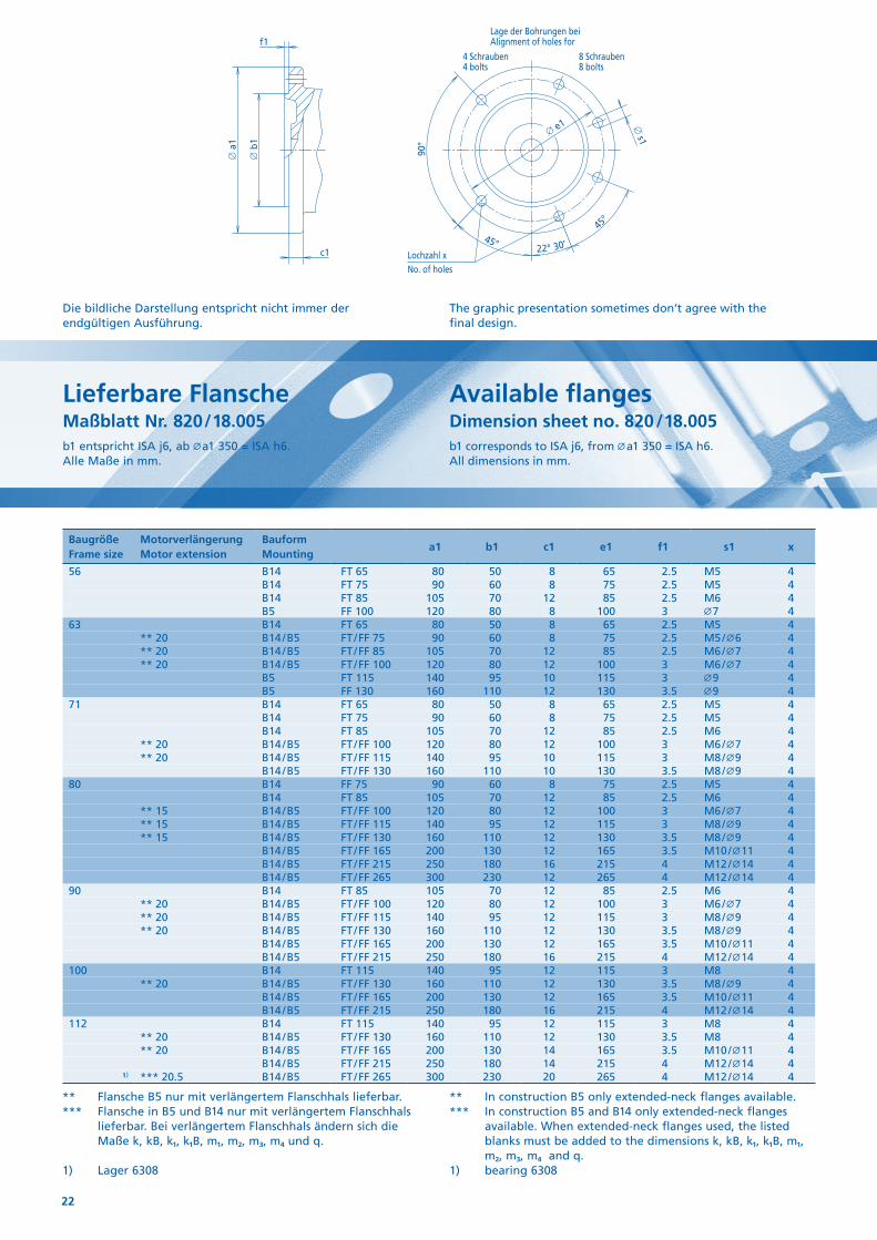
Die bildliche Darstellung entspricht nicht immer der endgültigen Ausführung.
The graphic presentation sometimes don’t agree with the final design.
Lieferbare FlanscheMaßblatt Nr. 820 / 18.005b1 entspricht ISA j6, ab a1 350 = ISA h6. Alle Maße in mm.
Available flangesDimension sheet no. 820 / 18.005b1 corresponds to ISA j6, from a1 350 = ISA h6. All dimensions in mm.
∅ e1
22° 30’45°
45°
No. of holes
Lage der Bohrungen beiAlignment of holes for
8 Schrauben8 bolts
4 Schrauben4 bolts
f1
∅ a
1
∅ b
1c1
90°
∅ s1
Lochzahl x
** Flansche B5 nur mit verlängertem Flanschhals lieferbar.*** Flansche in B5 und B14 nur mit verlängertem Flanschhals
lieferbar. Bei verlängertem Flanschhals ändern sich die Maße k, kB, k1, k1B, m1, m2, m3, m4 und q.
1) Lager 6308
** In construction B5 only extended-neck flanges available.*** In construction B5 and B14 only extended-neck flanges
available. When extended-neck flanges used, the listed blanks must be added to the dimensions k, kB, k1, k1B, m1, m2, m3, m4 and q.
1) bearing 6308
Baugröße Frame size
Motorverlängerung Motor extension
Bauform Mounting
a1 b1 c1 e1 f1 s1 x
56 B14 FT 65 80 50 8 65 2.5 M5 4B14 FT 75 90 60 8 75 2.5 M5 4B14 FT 85 105 70 12 85 2.5 M6 4B5 FF 100 120 80 8 100 3 7 4
63 B14 FT 65 80 50 8 65 2.5 M5 4** 20 B14 / B5 FT / FF 75 90 60 8 75 2.5 M5 / 6 4** 20 B14 / B5 FT / FF 85 105 70 12 85 2.5 M6 / 7 4** 20 B14 / B5 FT / FF 100 120 80 12 100 3 M6 / 7 4
B5 FT 115 140 95 10 115 3 9 4B5 FF 130 160 110 12 130 3.5 9 4
71 B14 FT 65 80 50 8 65 2.5 M5 4B14 FT 75 90 60 8 75 2.5 M5 4B14 FT 85 105 70 12 85 2.5 M6 4
** 20 B14 / B5 FT / FF 100 120 80 12 100 3 M6 / 7 4** 20 B14 / B5 FT / FF 115 140 95 10 115 3 M8 / 9 4
B14 / B5 FT / FF 130 160 110 10 130 3.5 M8 / 9 480 B14 FF 75 90 60 8 75 2.5 M5 4
B14 FT 85 105 70 12 85 2.5 M6 4** 15 B14 / B5 FT / FF 100 120 80 12 100 3 M6 / 7 4** 15 B14 / B5 FT / FF 115 140 95 12 115 3 M8 / 9 4** 15 B14 / B5 FT / FF 130 160 110 12 130 3.5 M8 / 9 4
B14 / B5 FT / FF 165 200 130 12 165 3.5 M10 / 11 4B14 / B5 FT / FF 215 250 180 16 215 4 M12 / 14 4B14 / B5 FT / FF 265 300 230 12 265 4 M12 / 14 4
90 B14 FT 85 105 70 12 85 2.5 M6 4** 20 B14 / B5 FT / FF 100 120 80 12 100 3 M6 / 7 4** 20 B14 / B5 FT / FF 115 140 95 12 115 3 M8 / 9 4** 20 B14 / B5 FT / FF 130 160 110 12 130 3.5 M8 / 9 4
B14 / B5 FT / FF 165 200 130 12 165 3.5 M10 / 11 4B14 / B5 FT / FF 215 250 180 16 215 4 M12 / 14 4
100 B14 FT 115 140 95 12 115 3 M8 4** 20 B14 / B5 FT / FF 130 160 110 12 130 3.5 M8 / 9 4
B14 / B5 FT / FF 165 200 130 12 165 3.5 M10 / 11 4B14 / B5 FT / FF 215 250 180 16 215 4 M12 / 14 4
112 B14 FT 115 140 95 12 115 3 M8 4** 20 B14 / B5 FT / FF 130 160 110 12 130 3.5 M8 4** 20 B14 / B5 FT / FF 165 200 130 14 165 3.5 M10 / 11 4
B14 / B5 FT / FF 215 250 180 14 215 4 M12 / 14 41) *** 20.5 B14 / B5 FT / FF 265 300 230 20 265 4 M12 / 14 4
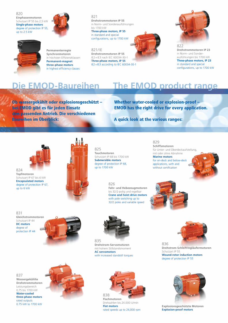
Die EMOD-Baureihen
820EinphasenmotorenSchutzart IP 55 bis 2,5 kWSingle-phase motorsdegree of protection IP 55, up to 2.5 kW
821Drehstrommotoren IP 55in Norm- und Sonderausführungen bis 1700 kWThree-phase motors, IP 55in standard and special configurations, up to 1700 kW
821 / IEDrehstrommotoren IP 55IE2 + IE3 nach IEC 60034-30-1 Three-phase motors, IP 55IE2 + IE3 according to IEC 60034-30-1
822 Drehstrommotoren IP 23in Norm- und Sonder-ausführungen bis 1700 kWThree-phase motors, IP 23in standard and special configurations, up to 1700 kW
824 TopfmotorenSchutzart IP 67 bis 6 kWEncapsulated motorsdegree of protection IP 67, up to 6 kW
825 TauchmotorenSchutzart IP 68 bis 1700 kWSubmersible motorsdegree of protection IP 68, up to 1700 kW
826Fahr- und Hebezeugmotorenbis 32/2-polig und regelbarCrane and hoist drive motorswith pole switching up to 32/2 poles and variable speed
829Schiffsmotorenfür Unter- und Oberdeckaufstellung, mit oder ohne AbnahmeMarine motorsfor on-deck and below-deck applications, with and without certification
831GleichstrommotorenSchutzart IP 44DC motorsdegree of protection IP 44
835Drehstrom-Servomotorenmit hohem StillstandsmomentAC servomotorswith increased standstill torques
836Drehstrom-SchleifringläufermotorenSchutzart IP 55Wound-rotor induction motorsdegree of protection IP 55
Explosionsgeschützte MotorenExplosion-proof motors
837Wassergekühlte Drehstrommotoren Leistungsbereich 0,75 bis 1700 kWWater-cooled three-phase motorsrated outputs 0.75 kW to 1700 kW
838 FlachmotorenDrehzahlen bis 24.000 U/minFlat motorsrated speeds up to 24,000 rpm
PermanenterregteSynchronmotorenin höchsten EffizienzklassenPermanent-magnetthree-phase motorsin highest efficiency classes
The EMOD product range
Ob wassergekühlt oder explosionsgeschützt – bei EMOD gibt es für jeden Einsatz den passenden Antrieb. Die verschiedenen Baureihen im Überblick:
Whether water-cooled or explosion-proof –EMOD has the right drive for every application. A quick look at the various ranges:
© c
re ar
t.de