Embed Size (px)
Citation preview

Electric Circuits 5
Advanced Circuit Analysis
Advanced Circuit AnalysisQuestion 1
Because 1A = 1000mA
i. 5 mA = 0.005 Aii. 150 mA = 0.15 Aiii.0.3 A = 300 mAiv. 0.042 A = 42 mA
??
??
??
??
Advanced Circuit AnalysisQuestion 2
Because 1k = 1000
i. 3.5k = 3500 ii. 25000 = 25 kiii.0.45k = 450 iv. 22 = 0.22 k
??
??
??
??
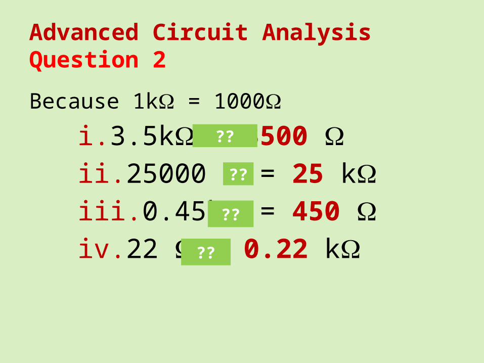
Advanced Circuit Analysis
3. If the current through the circuit opposite is 600mA, what is the EMF of the battery?
V = ? I = 600mA = 0.6A R = 20
V = IRV = 0.6 20V = 12V
V
I R
P = VI = I2R = =

Advanced Circuit Analysis
4. What power is being dissipated in the resistor opposite?
P = ? V = 6V R = 10P = P = P = 3.6W

Advanced Circuit Analysis
5. What is the resistance of a globe rated at 200mW when it is being driven by a 60V battery?
R = ? P = 200mW = 0.2W V = 6V
P = R = R = R = 180

Advanced Circuit Analysis
6. What is the power (in mW) being used by an LED that has 0.70V across it and a current of 5.0mA flowing through it?
P = ? V = 0.70V I = 5.0mA = 0.005A
P = VIP = 0.7 0.05P = 0.035WP = 35mW
Advanced Circuit Analysis
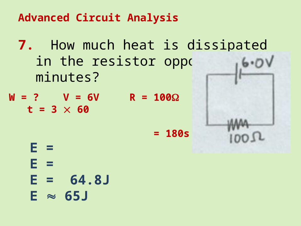
7. How much heat is dissipated in the resistor opposite in 3 minutes?
W = ? V = 6V R = 100 t = 3 60 = 180s
E = E = E = 64.8JE 65J
Advanced Circuit Analysis
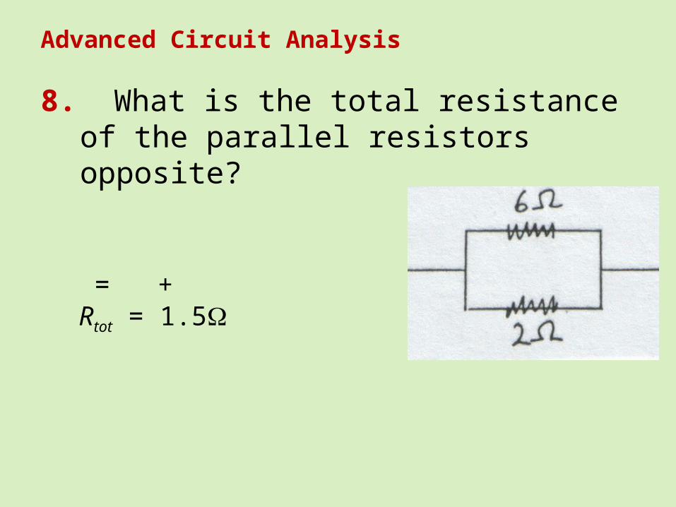
8. What is the total resistance of the parallel resistors opposite?
= + Rtot = 1.5
Advanced Circuit Analysis
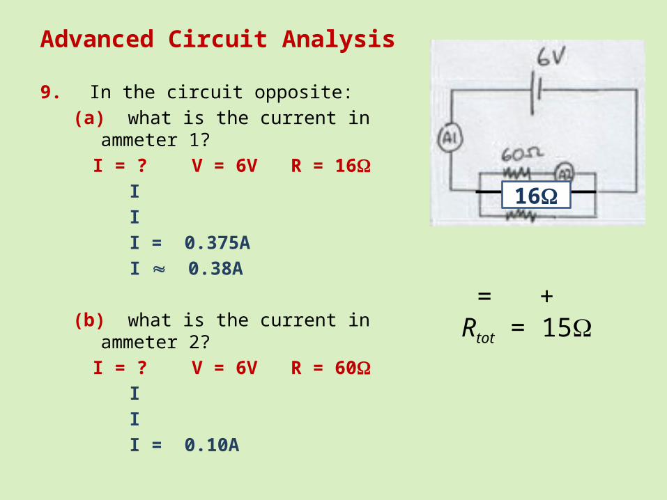
9. In the circuit opposite:(a) what is the current in ammeter 1?
I = ? V = 6V R = 16I
I
I = 0.375A
I 0.38A
(b) what is the current in ammeter 2?I = ? V = 6V R = 60
I
I
I = 0.10A
= + Rtot = 15
16

Advanced Circuit Analysis
10. Assuming the battery opposite is ideal? (a) What is the total resistance of the circuit?
Rtot = 2 + 4
Rtot = 6
= + Rtot = 4
4

Advanced Circuit Analysis
10. Assuming the battery opposite is ideal? (b) What current will flow?
I = ? V = 12V R = 6I
I
I = 2.0A
4
Advanced Circuit Analysis
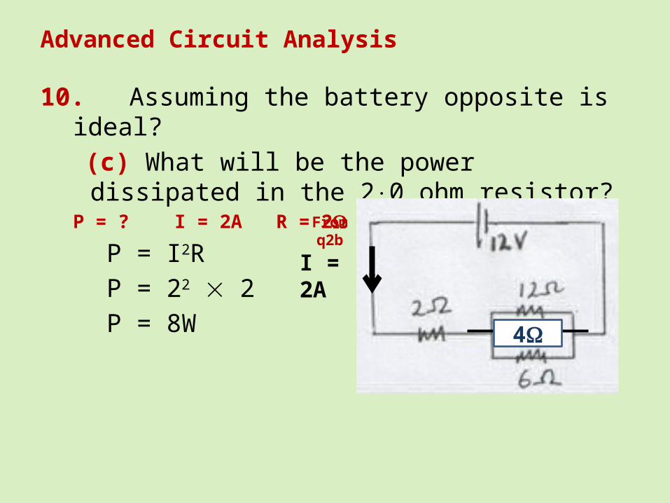
10. Assuming the battery opposite is ideal? (c) What will be the power dissipated in the
20 ohm resistor?P = ? I = 2A R = 2
P = I2RP = 22 2P = 8W 4
From q2b
I = 2A

Advanced Circuit Analysis
10. Assuming the battery opposite is ideal? (d) What will be the power drain on the
battery?P = ? I = 2A V = 12V
P = VIP = 12 2P = 24W 4
I = 2A
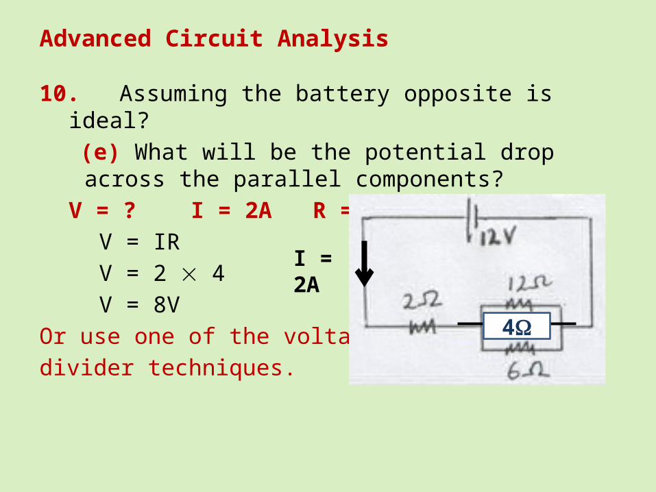
Advanced Circuit Analysis
10. Assuming the battery opposite is ideal? (e) What will be the potential drop across the
parallel components?V = ? I = 2A R = 4V
V = IRV = 2 4V = 8V
Or use one of the voltagedivider techniques.
4
I = 2A

Advanced Circuit Analysis
10. Assuming the battery opposite is ideal? (f) What current will flow through the 60 ohm resistor? Method 1 using Vparallel
I = ? V = 8V R = 6I
I
I = 1.333A
Method 2 –I divider formula
2
4
I = 2A From q8f8V
Method 3 – Ratios I6 : I12
: since I 12:6 2:1So I6 will be 2 part out of 1 of Itot
2 3 1 = 1.333 A

Advanced Circuit Analysis
11. What is Vout?
Method 1 – Every reliable formulaVout
= ? Vin = 16V RD = 6000 Ω Rout= 2000Ω
4.0V
Method 2 – Formula in your headRout is of the total resistance so
4.0V
Method 3 – RatiosRout : RD
2:2 1:3So Vout will be 1 part out of 4 of Vin
16 4 1 = 4.0V
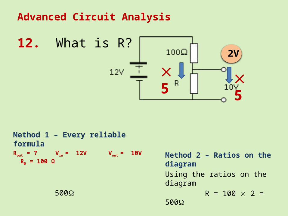
Advanced Circuit Analysis
12. What is R?
Method 1 – Every reliable formulaRout = ? Vin
= 12V Vout = 10V RD = 100 Ω
500
Method 2 – Ratios on the diagram
Using the ratios on the diagram R = 100 2 = 500
2V
55

Advanced Circuit Analysis
13. What is R?
Method 1 – Every reliable formulaRD = ? Vin
= 30V Vout = 5.0V Rout = 2000 Ω
10000
10k
Method 2 – Ratios on the diagram
Using the ratios on the diagram R = 2k 5 = 10k
25V
55
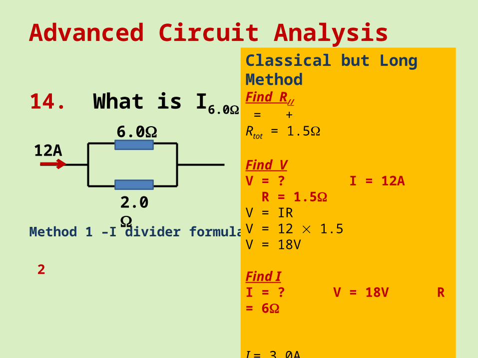
Advanced Circuit Analysis
14. What is I6.0?
Method 1 –I divider formula
2
2.0
6.012A
Classical but Long MethodFind R//
= + Rtot = 1.5
Find VV = ? I = 12A R = 1.5V = IRV = 12 1.5V = 18V
Find II = ? V = 18V R = 6 I = 3.0A

Circuit Design
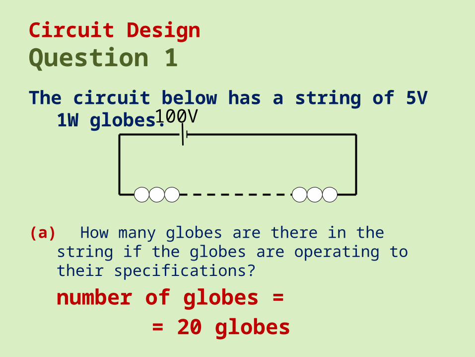
Circuit DesignQuestion 1The circuit below has a string of 5V 1W globes.
(a) How many globes are there in the string if the globes are operating to their specifications?
number of globes = = 20 globes
100V

Circuit DesignQuestion 1The circuit below has a string of 5V 1W globes.
(b) What is the current flowing in the circuit?
circuit current = current on 1 globe
100V
I = ?
V = 5V
P = 1W
P = VI
I
I
I = 0.20A

Circuit DesignQuestion 2
The circuit for a small set of Christmas tree lights is shown below.
The voltage supply (shown as a DC battery) is 240V. The complete circuit is designed to consume a total of 160W. Which of the following best describes the correct labelling for the lights in the circuit?
A. 20W; 30VB. 20W; 240VC. 160W; 30VD. 30W; 20V
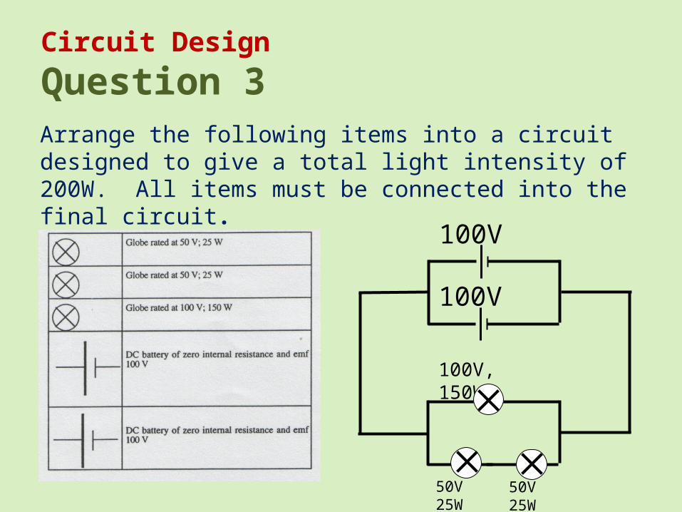
Circuit Design
Question 3Arrange the following items into a circuit designed to give a total light intensity of 200W. All items must be connected into the final circuit.
100V
100V
50V 25W
100V, 150W
50V 25W

Circuit DesignQuestion 4(b) How much current will be flowing through each battery?
100V
100V
50V 25W
100V, 150W
50V 25W
Find I in 150W Globe
I = ?
V = 100V
P = 150WP = VI
I
I
I = 1.5A
Find I in 25W Globe
I = ?
V = 50V
P = 25WP = VI
I
I
I = .5A
Total Current = 1.5 + 0.5 = 2.0ASo current through each battery will be 1.0A
1.5A
0.5A2.0A
2.0A
1.0A
1.0A

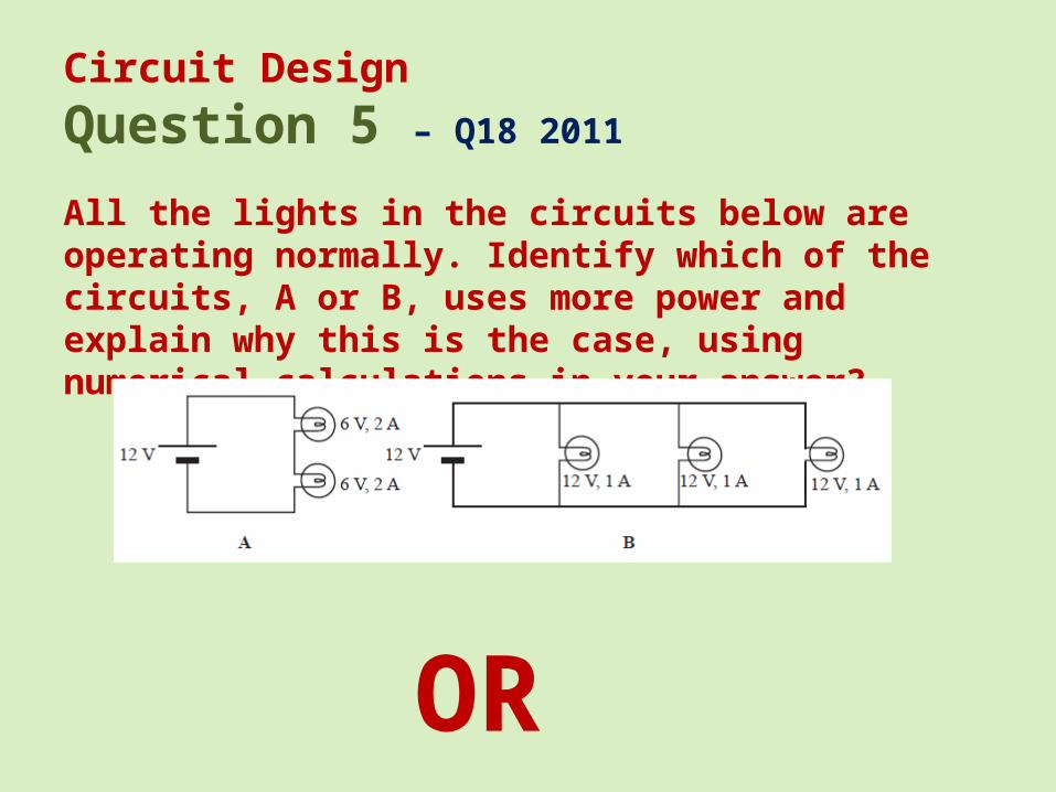
Circuit DesignQuestion 5 – Q18 2011
All the lights in the circuits below are operating normally. Identify which of the circuits, A or B, uses more power and explain why this is the case, using numerical calculations in your answer?
P = VI
P = 12 × 2
P= 24W
P = ?
V = 12V
I = 2.0A
P = VI
P = 12 × 3
P= 36W
P = ?
V = 12V
I = 3.0A
Circuit B uses more power
In Circuit A In Circuit B
Examiners CommentSeries and parallel circuits continue to cause difficulties for some students. Many were unable to work out how much current was flowing in each circuit. It was common for circuit A to have 4 A and circuit B to have 1 A. Other students tried unsuccessfully to obtain the total effective resistance of the circuits
55%
Circuit DesignQuestion 5 – Q18 2011
All the lights in the circuits below are operating normally. Identify which of the circuits, A or B, uses more power and explain why this is the case, using numerical calculations in your answer?
OR

Circuit DesignQuestion 5 – Q18 2011
All the lights in the circuits below are operating normally. Identify which of the circuits, A or B, uses more power and explain why this is the case, using numerical calculations in your answer?
Pglobe = VI
P = 6 × 2
P= 12W
Pglobe = ?
V = 6V
I = 2.0A
Pglobe = VI
P = 12 × 1
P= 12W
Pglobe = ?
V = 12V
I = 1.0A
Ptotal = 2 × 12 = 24W
55%
Ptotal = 3 × 12 = 36W
Examiners CommentSeries and parallel circuits continue to cause difficulties for some students. Many were unable to work out how much current was flowing in each circuit. It was common for circuit A to have 4 A and circuit B to have 1 A. Other students tried unsuccessfully to obtain the total effective resistance of the circuits
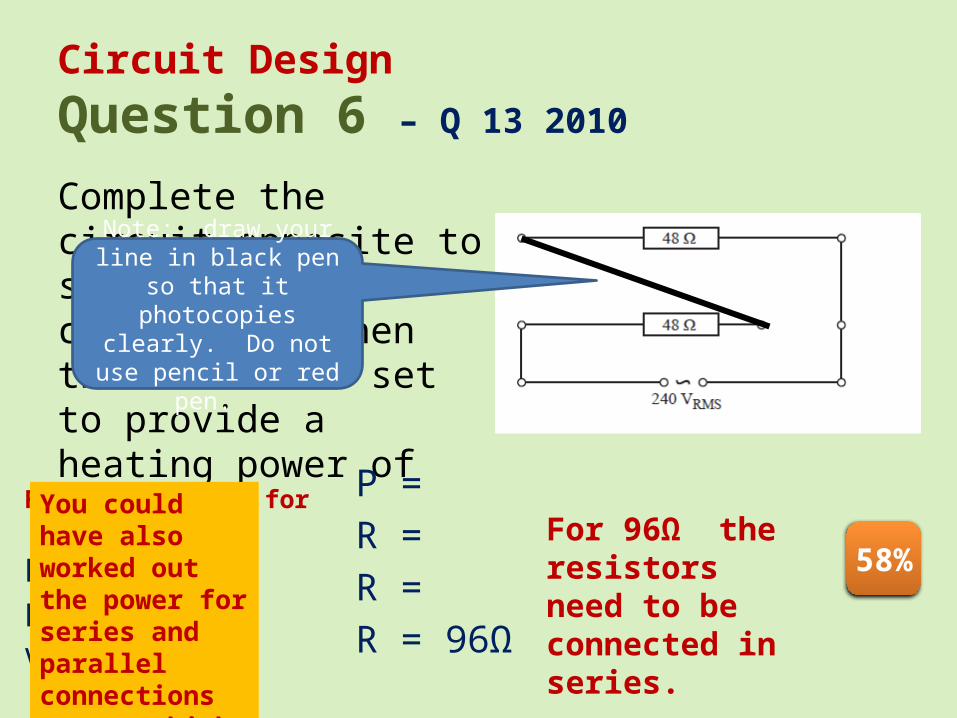
Circuit DesignQuestion 6 – Q 13 2010
Complete the circuit opposite to show the connections when the heater is set to provide a heating power of 600 W.
Find R required for 600W
R = ?
P = 600
V = 240VRMS
P =
R =
R =
R = 96Ω
For 96Ω the resistors need to be connected in series.
Note: draw your line in black pen so that it
photocopies clearly. Do not use pencil or red pen.
58%
You could have also worked out the power for series and parallel connections to see which gives 600W


![Circuit Network Analysis - [Chapter4] Laplace Transform](https://img.pdfslide.tips/doc/110x75/55ca3f16bb61eb15518b4621/circuit-network-analysis-chapter4-laplace-transform.jpg)


![Circuit Network Analysis - [Chapter2] Sinusoidal Steady-state Analysis](https://img.pdfslide.tips/doc/110x75/55d03589bb61ebd3698b46c3/circuit-network-analysis-chapter2-sinusoidal-steady-state-analysis.jpg)