Embed Size (px)
Citation preview
www.epcos.com
EPCOS Product Profile 2018
EMC FiltersEMV-Filter

2 © EPCOS AG 2017
3© EPCOS AG 2017
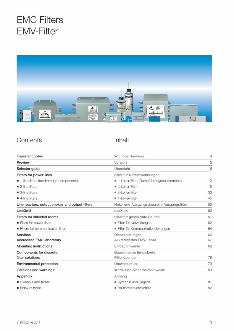
EMC FiltersEMV-Filter
Contents
Important notes 4
Preview 5
Selector guide 6
Filters for power lines
�� 1-line filters (feedthrough components) 12
�� 2-line filters 15
�� 3-line filters 32
�� 4-line filters 45
Line reactors, output chokes and output filters 50
LeaXield 60
Filters for shielded rooms 61
�� Filtes for power lines 62
�� Filters for communication lines 64
Services 66 Accredited EMC laboratory 67
Mounting instructions 69
Components for discrete filter solutions 76
Environmental protection 79
Cautions and warnings 80
Appendix
�� Symbols and terms 81
�� Index of types 82
Inhalt
Wichtige Hinweise
Vorwort
Übersicht
Filter für Netzanwendungen
�� 1-Leiter-Filter (Durchführungsbauelemente)
�� 2-Leiter-Filter
�� 3-Leiter-Filter
�� 4-Leiter-Filter
Netz- und Ausgangsdrosseln, Ausgangsfilter
LeaXield
Filter für geschirmte Räume
�� Filter für Netzleitungen
�� Filter für Kommunikationsleitungen
Dienstleistungen Akkreditiertes EMV-Labor
Einbauhinweise
Bauelemente für diskrete Filterlösungen
Umweltschutz
Warn- und Sicherheitshinweise
Anhang
�� Symbole und Begriffe
�� Bauformenverzeichnis
4 © EPCOS AG 2017Please read Important notes on page 4 and Cautions and warnings on page 80.Bitte beachten Sie die Seite 4 Wichtige Hinweise sowie die Warn- und Sicherheitshinweise auf Seite 80.
Important NotesWichtige Hinweise
The following applies to all products named in this publication:
1. Some parts of this publication contain statements about the suitability of our products for certain areas of application. These statements are based on our knowledge of typical requirements that are often placed on our products in the areas of application concerned. We nevertheless expressly point out that such statements cannot be regarded as binding state-ments about the suitability of our products for a particular customer application. As a rule, EPCOS is either unfamiliar with individual customer applications or less familiar with them than the customers themselves. For these reasons, it is always ultimately incumbent on the customer to check and decide whether an EPCOS product with the properties described in the product specification is suitable for use in a particular customer application.
2. We also point out that in individual cases, a malfunction of electronic components or failure before the end of their usual service life cannot be completely ruled out in the current state of the art, even if they are operated as specified. In customer applications requiring a very high level of operational safety and especially in customer applications in which the malfunction or failure of an electronic component could endanger human life or health (e.g. in accident prevention or lifesaving systems), it must therefore be ensured by means of suitable design of the customer application or other action taken by the customer (e.g. installation of protective circuitry or redun-dancy) that no injury or damage is sustained by third parties in the event of malfunction or failure of an electronic component.
3. The warnings, cautions and product-specific notes must be observed.
4. In order to satisfy certain technical requirements, some of the products described in this publication may contain substances subject to restric-tions in certain jurisdictions (e.g. because they are classed as hazard-ous). Useful information on this will be found in our Material Data Sheets on the Internet (www.epcos.com/material). Should you have any more detailed questions, please contact our sales offices.
5. We constantly strive to improve our products. Consequently, the products described in this publication may change from time to time. The same is true of the corresponding product specifications. Please check therefore to what extent product descriptions and specifications contained in this publication are still applicable before or when you place an order. We also reserve the right to discontinue production and delivery of products. Consequently, we cannot guarantee that all products named in this publica-tion will always be available. The aforementioned does not apply in the case of individual agreements deviating from the foregoing for customer-specific products.
6. Unless otherwise agreed in individual contracts, all orders are subject to the current version of the “General Terms of Delivery for Products and Services in the Electrical Industry” published by the German Electrical and Electronics Industry Association (ZVEI).
7. The trade names EPCOS, Alu-X, CeraDiode, CeraLink, CeraPad, CeraPlas, CSMP, CSSP, CTVS, DeltaCap, DigiSiMic, DSSP, ExoCore, FilterCap, FormFit, LeaXield, MiniBlue, MiniCell, MKD, MKK, MotorCap, PCC, Phase-Cap, PhaseCube, PhaseMod, PhiCap, PQSine, SIFERRIT, SIFI, SIKOREL, SilverCap, SIMDAD, SiMic, SIMID, SineFormer, SIOV, SIP5D, SIP5K, TFAP, ThermoFuse, WindCap are trademarks registered or pending in Europe and in other countries. Further information will be found on the Internet at www.epcos.com/trademarks.
Für alle in dieser Publikation genannten Produkte gilt:
1. Diese Publikation enthält an einigen Stellen Aussagen über die Eignung unserer Produkte für bestimmte Anwendungsgebiete. Diese Aussagen basieren auf unserer Kenntnis von typischen Anforderungen, die auf den ge-nannten Anwendungsgebieten häufig an unsere Produkte gestellt werden. Wir weisen aber ausdrücklich darauf hin, dass derartige Aussagen nicht als verbindliche Aussagen zur Eignung unserer Produkte für eine be-stimmte Kundenanwendung zu werten sind. In aller Regel kennt EPCOS die einzelne Kundenanwendung entweder nicht oder ist mit der Anwendung und ihren Anforderungen weniger vertraut als der Kunde selbst. Es obliegt deshalb letztlich immer dem Kunden, zu prüfen und zu entscheiden, ob ein EPCOS-Produkt mit seinen in der Produktspezifikation beschriebenen Eigen-schaften für den Einsatz in der jeweiligen individuellen Kundenanwendung geeignet ist.
2. Außerdem weisen wir darauf hin, dass nach dem derzeitigen Stand der Technik selbst bei spezifikationsgemäßem Betrieb in Einzelfällen eine Fehlfunktion elektronischer Bauelemente oder ein Ausfall vor Ende ihrer üblichen Lebensdauer nicht vollständig auszuschließen ist. Bei Kunden-anwendungen, welche ein sehr hohes Maß an Betriebssicherheit erfordern und insbesondere bei Kundenanwendungen, bei denen eine Fehlfunktion oder ein Ausfall eines elektronischen Bauelementes zu einer Gefährdung von Gesundheit oder Leben von Menschen führen könnte (z. B. unfallverhütende oder lebensschützende Systeme), muss deshalb durch geeignete Konstruk-tion der Kundenanwendung oder durch sonstige kundenseitige Maßnahmen (z. B. durch Einbau von Schutzschaltungen oder Redundanzen) dafür ge-sorgt werden, dass auch bei Fehlfunktion oder Ausfall eines elektronischen Bauelementes keine Verletzung von Rechtsgütern Dritter eintritt.
3. Warn- und Sicherheitshinweise sowie produktspezifischen Anmerkun-gen sind unbedingt zu beachten.
4. Um bestimmten technischen Anforderungen gerecht zu werden, kön-nen einige der in dieser Publikation aufgeführten Produkte Substan-zen enthalten, die nach länderspezifischen Regelungen Restriktionen unterliegen (z. B. weil sie als gefährlich eingestuft werden). Nützliche Informationen dazu enthalten unsere Materialdatenblätter im Internet (www.epcos.de/material). Bei weitergehenden Fragen wenden Sie sich bitte an unsere Vertriebsbüros.
5. Wir bemühen uns laufend, unsere Produkte zu verbessern. Infolge dessen ändern sich die in dieser Publikation beschriebenen Produkte von Zeit zu Zeit. Gleiches gilt auch für die entsprechenden Produktspezifikationen. Vergewissern Sie sich deshalb vor oder bei Ihrer Bestellung, inwieweit die in der vorliegenden Publikation angegebenen Produktbeschreibungen und Produktspezifikationen noch gelten. Im übrigen behalten wir uns vor, die Produktion und Lieferung von Produkten einzustellen. Eine Gewähr für die dauerhafte Verfügbarkeit aller in dieser Publikation genannten Produkte können wir deshalb nicht übernehmen. Die vorstehenden Regelungen gelten nicht, sofern in Hinblick auf kundenspezifische Bauteile abweichende Verein-barungen getroffen werden.
6. Außer in Fällen, in denen abweichende individualvertragliche Vereinbarungen getroffen werden, gelten für Bestellungen die jeweils aktuell vom Zent-ralverband Elektrotechnik- und Elektronikindustrie e.V. (ZVEI) herausge-gebenen „Allgemeinen Lieferbedingungen für Erzeugnisse und Leistun-gen der Elektroindustrie“.
7. Die Bezeichnungen EPCOS, Alu-X, CeraDiode, CeraLink, CeraPad, CeraPlas, CSMP, CSSP, CTVS, DeltaCap, DigiSiMic, DSSP, ExoCore, FilterCap, FormFit, LeaXield, MiniBlue, MiniCell, MKD, MKK, MotorCap, PCC, Phase-Cap, PhaseCube, PhaseMod, PhiCap, PQSine, SIFERRIT, SIFI, SIKOREL, SilverCap, SIMDAD, SiMic, SIMID, SineFormer, SIOV, SIP5D, SIP5K, TFAP, ThermoFuse, WindCap sind in Europa und in anderen Ländern registrierte oder zum Schutz angemeldete Marken. Weitere Informationen hierzu finden Sie im Internet unter www.epcos.de/trademarks.
5© EPCOS AG 2017Please read Important notes on page 4 and Cautions and warnings on page 80.
Bitte beachten Sie die Seite 4 Wichtige Hinweise sowie die Warn- und Sicherheitshinweise auf Seite 80.
PreviewVorwort
Electromagnetic compatibility is indispensable in today‘s products, and EMC components are the key to ensuring it. This publication is intended to help you choose the right solutions, and presents our broad selection of chokes and filters for power line applications. We produce these com-ponents in Szombathely (Hungary) and Hongqi (China).
When it comes to EMC, think EPCOS. Because EPCOSoffers you the world‘s biggest selection of EMC compo-nents, from arresters through chokes, filters and capaci-tors to varistors.
Our applications engineers develop individual EMC solu-tions for our customers, and support them with measure-ments – including on-site. Our test engineers conduct measurements and tests to international EMC standards in our own accredited laboratory in Regensburg, Germany. Tests from this laboratory can be used for the CE confor-mity declaration.
EPCOS is an EMC solution provider, supporting our cus-tomers throughout the entire product development cycle – from the design phase up to volume production. We offer solutions and make recommendations for optimization. In brief, EMC from a single source!
Let our creativity and competence contribute to your suc-cess.
Wenn es darum geht, die elektromagnetische Verträglichkeit (EMV) sicherzustellen, sind EMV-Bauelemente unverzicht-bare Schlüsselprodukte. Diese Broschüre hilft Ihnen bei der Wahl der passenden EMV-Filter bzw. EMV-Drosseln. Wir fertigen diese Bauelemente in Szombathely (Ungarn) und Hongqi (China).
In Sachen EMV sind Sie bei EPCOS immer an der richtigen Adresse. EPCOS bietet das weltweit größte Spektrum an EMV-Bauelementen: Von Ableitern über Drosseln, Filtern und Kondensatoren bis hin zu Varistoren. Darüber hinaus entwickeln unsere Applikationsingenieure für unsere Kun-den auch individuelle EMV-Lösungen und unterstützen mit Messungen – auch vor Ort. Außerdem führen unsere Mess-ingenieure in einem eigenen, akkreditierten EMV-Labor in Regensburg protokollierte Messungen und Prüfungen nach internationalen EMV-Normen durch. Prüfberichte unseres Labors können für die CE-Konformitätserklärung herange-zogen werden.
Wir verstehen uns als EMV-Solution-Provider und unterstüt-zen Sie von Beginn an im gesamten Entwicklungszyklus Ihres Gerätes von der Konzeptionsphase bis zur Serien-fertigung. Wir bieten Ihnen Lösungen an und erarbeiten Optimierungsvorschläge, kurz: EMV aus einer Hand!
Nutzen deshalb auch Sie unsere Kreativität und jahrzehnte-lange Kompetenz für Ihren Erfolg.
6 © EPCOS AG 2017Please read Important notes on page 4 and Cautions and warnings on page 80.Bitte beachten Sie die Seite 4 Wichtige Hinweise sowie die Warn- und Sicherheitshinweise auf Seite 80.
Selector GuideÜbersicht
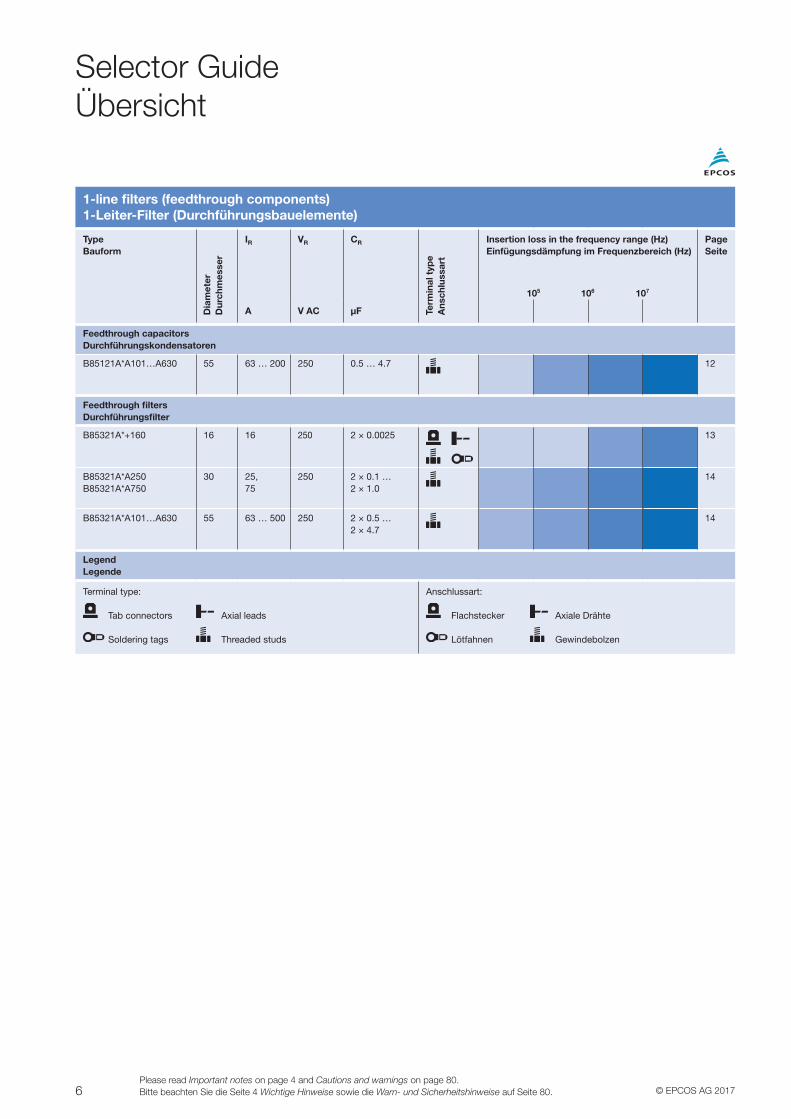
1-line filters (feedthrough components)1-Leiter-Filter (Durchführungsbauelemente)
TypeBauform
Dia
met
erD
urch
mes
ser
IR VR CR
Term
inal
typ
eA
nsch
luss
art
Insertion loss in the frequency range (Hz)Einfügungsdämpfung im Frequenzbereich (Hz)
PageSeite
A V AC µF
Feedthrough capacitorsDurchführungskondensatoren
B85121A*A101…A630 55 63 … 200 250 0.5 … 4.7 12
Feedthrough filtersDurchführungsfilter
B85321A*+160 16 16 250 2 × 0.0025
13
B85321A*A250B85321A*A750
30 25,75
250 2 × 0.1 …2 × 1.0
14
B85321A*A101…A630 55 63 … 500 250 2 × 0.5 …2 × 4.7
14
LegendLegende
Terminal type:
Tab connectors Axial leads
Soldering tags Threaded studs
Anschlussart:
Flachstecker Axiale Drähte
Lötfahnen Gewindebolzen
105 106 107
7© EPCOS AG 2017Please read Important notes on page 4 and Cautions and warnings on page 80.
Bitte beachten Sie die Seite 4 Wichtige Hinweise sowie die Warn- und Sicherheitshinweise auf Seite 80.
Selector GuideÜbersicht
2-line filters2-Leiter-Filter
TypeBauform
IR VR
Line
co
nnec
tio
nN
etza
rt
Des
ign
Bau
art
Term
inal
typ
eA
nsch
luss
art
Insertion loss in the frequency range (Hz)Einfügungsdämpfung im Frequenzbereich (Hz)
PageSeite
A V
General applications, IEC inlet filtersAllgemeine Anwendungen, IEC-Steckerfilter
B84771 1 … 20 250 AC/DC TT/TN C 15, 16
B84773 1 … 10 250 AC/DC TT/TN C 17
B84776 1 … 10 250 AC/DC TT/TN C 18
B84103 1 … 6 250 AC/DC TT/TN C 19
General applications, SIFI seriesAllgemeine Anwendungen, Baureihe SIFI
B84111F 2 … 36 250 AC/DC TT/TN C 20
B84112G 21
B84113H 22
B84111A 1 … 20 250 AC/DC TT/TN C 23
B84115E 25
General applications, PCB mountingAllgemeine Anwendungen, Leiterplattenbestückung
B84110A 0.5 … 6 250 AC/DC TT/TN P 26
B84110B 1.4 250 AC/DC TT/TN P 26
Converters and power electronicsUmrichter und Leistungselektronik
B84142A*R000 10 … 60 250 AC/DC TT/TN C 27
B84142A*G075 60 250 AC/DC TT/TN C 27
B84142A*166 10 … 30 250 AC/DC TT/TN C 28
B84142B*R000 8 … 25 250 AC/DC TT/TN C 27
B84142A*R122 8 … 180 300 AC/DC TT/TN C 29
B84142A*R123 12 … 100 520 AC/DC TT/TN C 29
B84742A*R190 25 … 130 500 AC1000 DC
TT/TN C 30
B84142A/C/J*S081 180 … 1600
1000 V DC1500 V DC
– C 31
LegendLegende
Design:C = Compact filter P = PCB filter
Terminal type:
Tab connectors IEC connectors Litz wires
Pins Threaded studs
Busbars Terminal blocks
Bauart:C = Kompaktfilter P = Leiterplattenfilter
Anschlussart:
Flachstecker IEC-Stecker Litzen
Stifte Gewindebolzen
Stromschienen Reihenklemmen
105 106 107
NEW
NEW
NEW
NEW
NEW
NEW
8 © EPCOS AG 2017Please read Important notes on page 4 and Cautions and warnings on page 80.Bitte beachten Sie die Seite 4 Wichtige Hinweise sowie die Warn- und Sicherheitshinweise auf Seite 80.
Selector GuideÜbersicht
3-line filters3-Leiter-Filter
TypeBauform
IR VR
Line
co
nnec
tio
nN
etza
rt
Des
ign
Bau
art
Term
inal
typ
eA
nsch
luss
art
Motor leadlength1)
Motorleitg.-Länge1)
Class Class
Insertion loss in the frequency range (Hz)Einfügungsdämpfung im Frequenzbereich (Hz)
PageSeite
A V C2 (m) C1 (m)
B84143A*166 10 … 35
520 AC TT/TN C
25 10 32
B84143A*R107 10 … 100
520 AC TT/TN C 25 10 33
B84143A*R105 8 … 150
520 AC TT/TN B 40 20 34
B84243A 3 … 306
305/530 AC
TT/TN B 50 25 35
B84143A*R000 8 … 180
480 AC TT/TN C 50 25 36
B84143B*R000 8 … 80
440 AC TT/TN C 100 50 37
B84143G*R110 8 … 220
520 AC TT/TN B
25 25 38
B84143B*R110 8 … 200
520 AC TT/TN B
50 25 39
B84143D*R127 16 … 200
530 AC TT/TN B 300 100 …200
40
B84143*R410 35 … 230
520 AC TT/TN B 100 50 41
B84143B*S080 180 … 1600
520 AC TT/TN C 25 10 42
B84143B*S081 760 AC TT/TN
B84143B*S020 150 … 2500
530 AC TT/TN C 50 20 43
B84143B*S021 760 AC TT/TN
B84143B*S024 690 AC IT 44
B84143A*R021 25 … 180
760 AC TT/TN C 50 25 44
LegendLegende
Design:C = Compact filter B = Book-size filter
Terminal type:
Litz wires Terminal blocks
Busbars Tab connector
Bauart:C = Kompaktfilter B = Buchfilter
Anschlussart:
Litzen Reihenklemmen
Stromschienen Flachstecker
1) Motor-lead lengths for observing the limits to DIN EN 61800-3 (2004) + A1 (2012) Typical values. These specifications are designed as a qualitative help in selecting the right filter. The maximum motor cable length depends on several factors, including the pulse frequency, the interference level of the converter and the capacitance of the motor cable: it may in an individual case diverge both upwards and downwards from the specified values. Observance of the limits must always be verified by relevant measurements. On this point, see also “Services” and “EMC laboratory”, page 66ff.
1) Motorleitungslängen zur Einhaltung der Grenzwerte nach DIN EN 61800-3 (2004) + A1 (2012) Typische Werte. Die vorliegenden Angaben sollen eine qualitative Hilfe in der Filterauswahl darstellen. Die maximale Motorleitungslänge hängt unter anderem von der Taktfrequenz, dem Störpegel des Umrichters und der Kapazität der Motorleitung ab und kann im Einzelfall von den genannten Werten sowohl nach oben als auch nach unten abweichen. Die Einhaltung der Grenzwerte ist immer durch entsprechende Messungen zu verifizieren. Siehe hierzu auch „Dienstleistungen“ und „EMV-Labor“, Seite 66ff.
105 106 107
NEW
NEW
9© EPCOS AG 2017Please read Important notes on page 4 and Cautions and warnings on page 80.
Bitte beachten Sie die Seite 4 Wichtige Hinweise sowie die Warn- und Sicherheitshinweise auf Seite 80.
4-line and customer-specific filters4-Leiter- und kundenspezifische Filter
TypeBauform
IR VR
Num
ber
of
lines
Anz
ahl d
er L
eite
r
Line
co
nnec
tio
nN
etza
rt
Des
ign
Bau
art
Term
inal
typ
eA
nsch
luss
art
Insertion loss in the frequency range (Hz)Einfügungsdämpfung im Frequenzbereich (Hz)
PageSeite
A V
4-line filters4-Leiter-Filter
B84144A*R120 8 … 200 520 AC 3 + N TT/TN C
45
B84144A*R140 8 … 200 520 AC 3 + N TT/TN C
46
B84144B*S120/S121 250 … 600 530 AC 3 + N TT/TN C 47
B84144A*R000 16 … 180 440 AC 3 + N TT/TN C 48
B84108 10, 20 440 AC 3 + N TT/TN C 49
B84131 6 … 125 440 AC 3 + N TT/TN C
49
LegendLegende
Design:C = Compact filter
Terminal type:
Tab connectors Terminal blocks
Threaded studs Busbars
Bauart:C = Kompaktfilter
Anschlussart:
Flachstecker Reihenklemmen
Gewindebolzen Stromschienen
105 106 107
Selector GuideÜbersicht
NEW
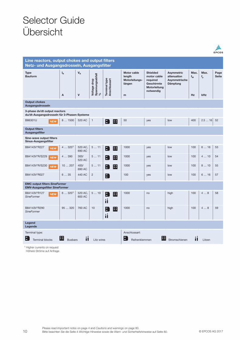
Line reactors, output chokes and output filtersNetz- und Ausgangsdrosseln, Ausgangsfilter
TypeBauform
IR VR
Volt
age
dro
pS
pann
ungs
abfa
ll% Te
rmin
al t
ype
Ans
chlu
ssar
t
Motor cable lengthMotorleitungs- längen
Shielded motor cable requiredGeschirmte Motorleitung notwendig
Asymmetric attenuationAsymmetrische Dämpfung
Max.fM
Max.fp
PageSeite
A V m Hz kHz
Line reactors and output chokesNetzdrosseln und Ausgangsdrosseln
Line reactorsNetzdrosseln
B86305L 4 … 390 520 AC 5
– – low – – 50
B86306A 14 … 418 520 AC 51
LegendLegende
Terminal type:
Terminal blocks Busbars
Anschlussart:
Reihenklemmen Stromschienen
NEW
NEW
10 © EPCOS AG 2017Please read Important notes on page 4 and Cautions and warnings on page 80.Bitte beachten Sie die Seite 4 Wichtige Hinweise sowie die Warn- und Sicherheitshinweise auf Seite 80.
Selector GuideÜbersicht
Line reactors, output chokes and output filtersNetz- und Ausgangsdrosseln, Ausgangsfilter
TypeBauform
IR VR
Volt
age
dro
pS
pan
nung
sab
fall
% Term
inal
typ
eA
nsch
luss
art
Motor cable lengthMotorleitungs- längen
Shielded motor cable requiredGeschirmte Motorleitung notwendig
Asymmetric attenuationAsymmetrische Dämpfung
Max.fM
Max.fp
PageSeite
A V m Hz kHz
Output chokesAusgangsdrosseln
3-phase dv/dt output reactorsdu/dt-Ausgangsdrosseln für 3-Phasen-Systeme
B86301U 8 … 1500 520 AC 1
50 yes low 400 2.5 … 16 52
Output filtersAusgangsfilter
Sine-wave output filtersSinus-Ausgangsfilter
B84143V*R227 4 … 3201) 520 AC, 690 AC
5 … 11
1000 yes low 100 6 … 16 53
B84143V*R/S229 4 … 390 300/ 520 AC
5 … 11
1000 yes low 100 4 … 10 54
B84143V*R/S230 10 … 207 400/ 690 AC
5 … 11
1000 yes low 100 8 … 10 55
B84143V*R027 6 … 35 440 AC 2 100 yes low 100 6 … 16 57
EMC output filters SineFormerEMV-Ausgangsfilter SineFormer
B84143V*R127SineFormer
6 … 3201) 520 AC, 600 AC
5 … 10
1000 no high 100 4 … 8 58
B84143V*R290SineFormer
95 … 320 760 AC 10
1000 no high 100 4 … 8 59
LegendLegende
Terminal type:
Terminal blocks Busbars Litz wires
Anschlussart:
Reihenklemmen Stromschienen Litzen
1) Higher currents on request Höhere Ströme auf Anfrage
NEW
NEW
NEW
NEW
NEW
11© EPCOS AG 2017Please read Important notes on page 4 and Cautions and warnings on page 80.
Bitte beachten Sie die Seite 4 Wichtige Hinweise sowie die Warn- und Sicherheitshinweise auf Seite 80.
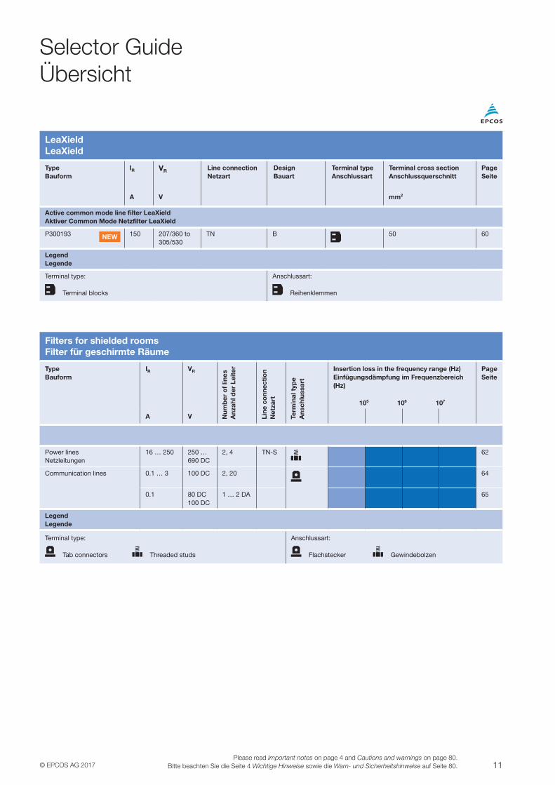
LeaXieldLeaXield
TypeBauform
IR VR Line connectionNetzart
DesignBauart
Terminal typeAnschlussart
Terminal cross sectionAnschlussquerschnitt
PageSeite
A V mm2
Active common mode line filter LeaXieldAktiver Common Mode Netzfilter LeaXield
P300193 150 207/360 to 305/530
TN B 50 60
LegendLegende
Terminal type:
Terminal blocks
Anschlussart:
Reihenklemmen
NEW
Filters for shielded roomsFilter für geschirmte Räume
TypeBauform
IR VR
Num
ber
of
lines
Anz
ahl d
er L
eite
r
Line
co
nnec
tio
nN
etza
rt
Term
inal
typ
eA
nsch
luss
art
Insertion loss in the frequency range (Hz)Einfügungsdämpfung im Frequenzbereich (Hz)
PageSeite
A V
Power lines Netzleitungen
16 … 250 250 …690 DC
2, 4 TN-S 62
Communication lines 0.1 … 3 100 DC 2, 20 64
0.1 80 DC100 DC
1 … 2 DA 65
LegendLegende
Terminal type:
Tab connectors Threaded studs
Anschlussart:
Flachstecker Gewindebolzen
105 106 107
Selector GuideÜbersicht
12 © EPCOS AG 2017Please read Important notes on page 4 and Cautions and warnings on page 80.Bitte beachten Sie die Seite 4 Wichtige Hinweise sowie die Warn- und Sicherheitshinweise auf Seite 80.
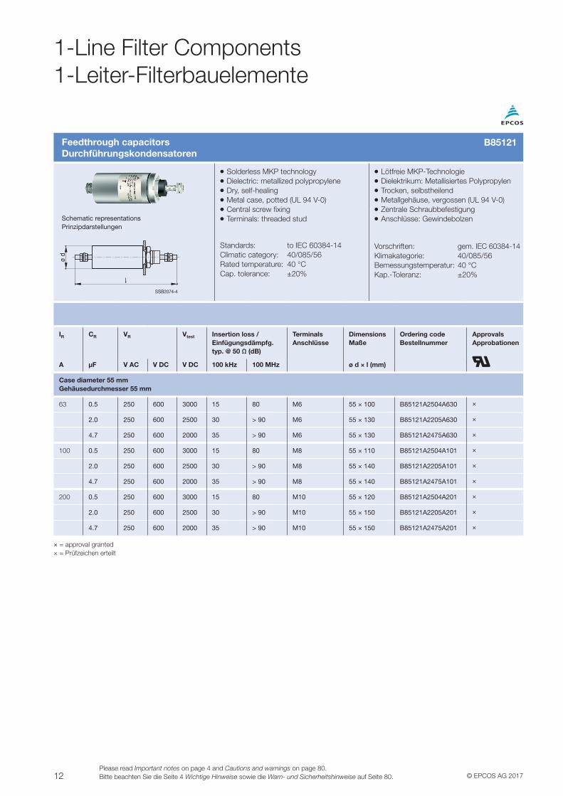
Feedthrough capacitorsDurchführungskondensatoren
VV Solderless MKP technologyVV Dielectric: metallized polypropyleneVV Dry, self-healingVV Metal case, potted (UL 94 V-0)VV Central screw fixingVV Terminals: threaded stud
Standards: to IEC 60384-14Climatic category: 40/085/56Rated temperature: 40 °CCap. tolerance: ±20%
VV Lötfreie MKP-TechnologieVV Dielektrikum: Metallisiertes PolypropylenVV Trocken, selbstheilendVV Metallgehäuse, vergossen (UL 94 V-0)VV Zentrale SchraubbefestigungVV Anschlüsse: Gewindebolzen
Vorschriften: gem. IEC 60384-14Klimakategorie: 40/085/56Bemessungstemperatur: 40 °CKap.-Toleranz: ±20%
Schematic representationsPrinzipdarstellungen
SSB2074-4
ø d
IR CR VR Vtest Insertion loss /Einfügungsdämpfg.typ. @ 50 Ω (dB)
TerminalsAnschlüsse
DimensionsMaße
Ordering codeBestellnummer
ApprovalsApprobationen
A µF V AC V DC V DC 100 kHz 100 MHz ø d × l (mm)
Case diameter 55 mmGehäusedurchmesser 55 mm
63 0.5 250 600 3000 15 80 M6 55 × 100 B85121A2504A630 ×
2.0 250 600 2500 30 > 90 M6 55 × 130 B85121A2205A630 ×
4.7 250 600 2000 35 > 90 M6 55 × 130 B85121A2475A630 ×
100 0.5 250 600 3000 15 80 M8 55 × 110 B85121A2504A101 ×
2.0 250 600 2500 30 > 90 M8 55 × 140 B85121A2205A101 ×
4.7 250 600 2000 35 > 90 M8 55 × 140 B85121A2475A101 ×
200 0.5 250 600 3000 15 80 M10 55 × 120 B85121A2504A201 ×
2.0 250 600 2500 30 > 90 M10 55 × 150 B85121A2205A201 ×
4.7 250 600 2000 35 > 90 M10 55 × 150 B85121A2475A201 ×
× = approval granted× = Prüfzeichen erteilt
1-Line Filter Components1-Leiter-Filterbauelemente
B85121
13© EPCOS AG 2017Please read Important notes on page 4 and Cautions and warnings on page 80.
Bitte beachten Sie die Seite 4 Wichtige Hinweise sowie die Warn- und Sicherheitshinweise auf Seite 80.
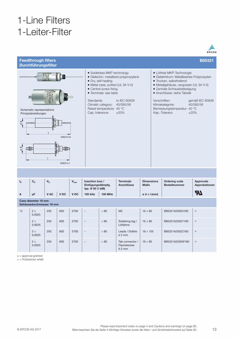
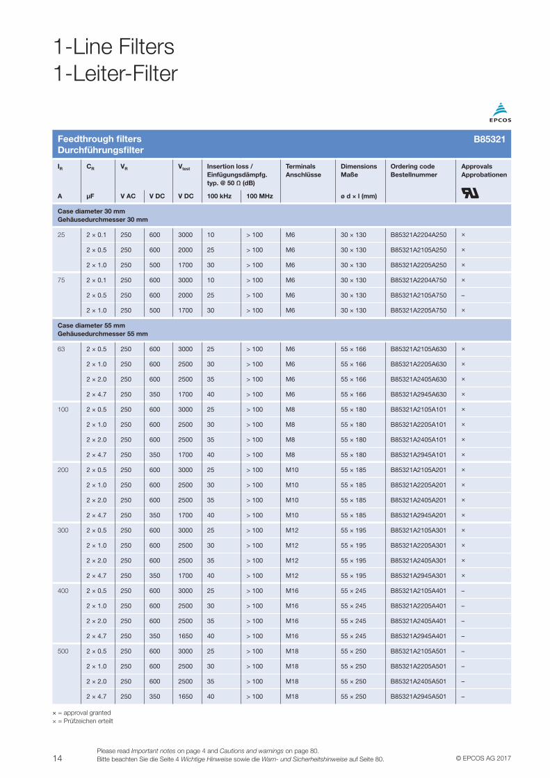
Feedthrough filtersDurchführungsfilter
VV Solderless MKP technologyVV Dielectric: metallized polypropyleneVV Dry, self-healingVV Metal case, potted (UL 94 V-0)VV Central screw fixingVV Terminals: see table
Standards: to IEC 60939Climatic category: 40/085/56Rated temperature: 40 °CCap. tolerance: ±20%
VV Lötfreie MKP-TechnologieVV Dielektrikum: Metallisiertes PolypropylenVV Trocken, selbstheilendVV Metallgehäuse, vergossen (UL 94 V-0)VV Zentrale SchraubbefestigungVV Anschlüsse: siehe Tabelle
Vorschriften: gemäß IEC 60939Klimakategorie: 40/085/56Bemessungstemperatur: 40 °CKap.-Toleranz: ±20%
Schematic representationsPrinzipdarstellungen
SSB2072-M
ø d
SSB2074-4
ø d
IR CR VR Vtest Insertion loss /Einfügungsdämpfg.typ. @ 50 Ω (dB)
TerminalsAnschlüsse
DimensionsMaße
Ordering codeBestellnummer
ApprovalsApprobationen
A µF V AC V DC V DC 100 kHz 100 MHz ø d × l (mm)
Case diameter 16 mmGehäusedurchmesser 16 mm
16 2 ×0.0025
250 600 2700 – > 80 M2 16 × 80 B85321A2502X160 ×
2 ×0.0025
250 600 2700 – > 80 Soldering tag / Lötfahne
16 × 80 B85321A2502Y160 ×
2 × 0.0025
250 600 2700 – > 80 Leads / Drähteø 2 mm
16 × 155 B85321A2502Z160 ×
2 ×0.0025
250 600 2700 – > 80 Tab connector /Flachstecker6.3 mm
16 × 90 B85321A2502W160 ×
× = approval granted× = Prüfzeichen erteilt
1-Line Filters1-Leiter-Filter
B85321
14 © EPCOS AG 2017Please read Important notes on page 4 and Cautions and warnings on page 80.Bitte beachten Sie die Seite 4 Wichtige Hinweise sowie die Warn- und Sicherheitshinweise auf Seite 80.
Feedthrough filtersDurchführungsfilter
IR CR VR Vtest Insertion loss /Einfügungsdämpfg.typ. @ 50 Ω (dB)
TerminalsAnschlüsse
DimensionsMaße
Ordering codeBestellnummer
ApprovalsApprobationen
A µF V AC V DC V DC 100 kHz 100 MHz ø d × l (mm)
Case diameter 30 mmGehäusedurchmesser 30 mm
25 2 × 0.1 250 600 3000 10 > 100 M6 30 × 130 B85321A2204A250 ×
2 × 0.5 250 600 2000 25 > 100 M6 30 × 130 B85321A2105A250 ×
2 × 1.0 250 500 1700 30 > 100 M6 30 × 130 B85321A2205A250 ×
75 2 × 0.1 250 600 3000 10 > 100 M6 30 × 130 B85321A2204A750 ×
2 × 0.5 250 600 2000 25 > 100 M6 30 × 130 B85321A2105A750 –
2 × 1.0 250 500 1700 30 > 100 M6 30 × 130 B85321A2205A750 ×
Case diameter 55 mmGehäusedurchmesser 55 mm
63 2 × 0.5 250 600 3000 25 > 100 M6 55 × 166 B85321A2105A630 ×
2 × 1.0 250 600 2500 30 > 100 M6 55 × 166 B85321A2205A630 ×
2 × 2.0 250 600 2500 35 > 100 M6 55 × 166 B85321A2405A630 ×
2 × 4.7 250 350 1700 40 > 100 M6 55 × 166 B85321A2945A630 ×
100 2 × 0.5 250 600 3000 25 > 100 M8 55 × 180 B85321A2105A101 ×
2 × 1.0 250 600 2500 30 > 100 M8 55 × 180 B85321A2205A101 ×
2 × 2.0 250 600 2500 35 > 100 M8 55 × 180 B85321A2405A101 ×
2 × 4.7 250 350 1700 40 > 100 M8 55 × 180 B85321A2945A101 ×
200 2 × 0.5 250 600 3000 25 > 100 M10 55 × 185 B85321A2105A201 ×
2 × 1.0 250 600 2500 30 > 100 M10 55 × 185 B85321A2205A201 ×
2 × 2.0 250 600 2500 35 > 100 M10 55 × 185 B85321A2405A201 ×
2 × 4.7 250 350 1700 40 > 100 M10 55 × 185 B85321A2945A201 ×
300 2 × 0.5 250 600 3000 25 > 100 M12 55 × 195 B85321A2105A301 ×
2 × 1.0 250 600 2500 30 > 100 M12 55 × 195 B85321A2205A301 ×
2 × 2.0 250 600 2500 35 > 100 M12 55 × 195 B85321A2405A301 ×
2 × 4.7 250 350 1700 40 > 100 M12 55 × 195 B85321A2945A301 ×
400 2 × 0.5 250 600 3000 25 > 100 M16 55 × 245 B85321A2105A401 –
2 × 1.0 250 600 2500 30 > 100 M16 55 × 245 B85321A2205A401 –
2 × 2.0 250 600 2500 35 > 100 M16 55 × 245 B85321A2405A401 –
2 × 4.7 250 350 1650 40 > 100 M16 55 × 245 B85321A2945A401 –
500 2 × 0.5 250 600 3000 25 > 100 M18 55 × 250 B85321A2105A501 –
2 × 1.0 250 600 2500 30 > 100 M18 55 × 250 B85321A2205A501 –
2 × 2.0 250 600 2500 35 > 100 M18 55 × 250 B85321A2405A501 –
2 × 4.7 250 350 1650 40 > 100 M18 55 × 250 B85321A2945A501 –
× = approval granted× = Prüfzeichen erteilt
1-Line Filters1-Leiter-Filter
B85321
15© EPCOS AG 2017Please read Important notes on page 4 and Cautions and warnings on page 80.
Bitte beachten Sie die Seite 4 Wichtige Hinweise sowie die Warn- und Sicherheitshinweise auf Seite 80.
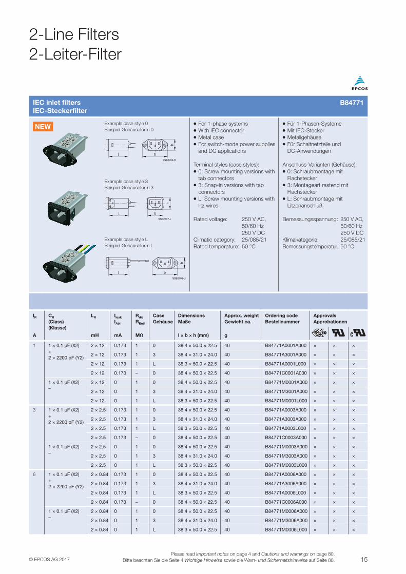
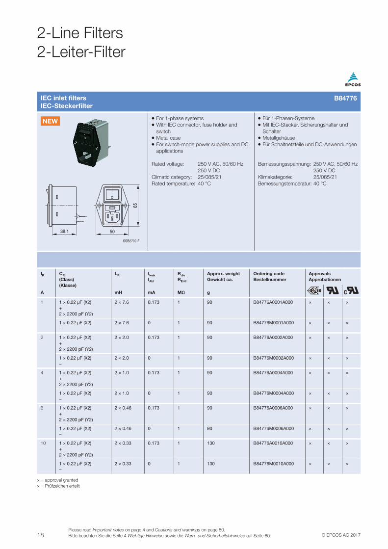
IEC inlet filtersIEC-Steckerfilter
Example case style 0Beispiel Gehäuseform 0
VV For 1-phase systemsVV With IEC connectorVV Metal caseVV For switch-mode power supplies and DC applications
Terminal styles (case styles):VV 0: Screw mounting versions with tab connectorsVV 3: Snap-in versions with tab connectorsVV L: Screw mounting versions with litz wires
Rated voltage: 250 V AC, 50/60 Hz 250 V DCClimatic category: 25/085/21Rated temperature: 50 °C
VV Für 1-Phasen-SystemeVV Mit IEC-SteckerVV MetallgehäuseVV Für Schaltnetzteile und DC-Anwendungen
Anschluss-Varianten (Gehäuse):VV 0: Schraubmontage mit FlachsteckerVV 3: Montageart rastend mit FlachsteckerVV L: Schraubmontage mit Litzenanschluß
Bemessungsspannung: 250 V AC, 50/60 Hz 250 V DCKlimakategorie: 25/085/21Bemessungstemperatur: 50 °C
Example case style 3Beispiel Gehäuseform 3
h
b
Example case style LBeispiel Gehäuseform L
h
b
IR CR
(Class)(Klasse)
LR Ileak
IAbl
Rdis
REntl
CaseGehäuse
DimensionsMaße
Approx. weightGewicht ca.
Ordering codeBestellnummer
ApprovalsApprobationen
A mH mA MΩ l × b × h (mm) g
1 1 × 0.1 μF (X2) +2 × 2200 pF (Y2)
2 × 12 0.173 1 0 38.4 × 50.0 × 22.5 40 B84771A0001A000 × × ×
2 × 12 0.173 1 3 38.4 × 31.0 × 24.0 40 B84771A3001A000 × × ×
2 × 12 0.173 1 L 38.3 × 50.0 × 22.5 40 B84771A0001L000 × × ×
2 × 12 0.173 – 0 38.4 × 50.0 × 22.5 40 B84771C0001A000 × × ×
1 × 0.1 μF (X2)–
2 × 12 0 1 0 38.4 × 50.0 × 22.5 40 B84771M0001A000 × × ×
2 × 12 0 1 3 38.4 × 31.0 × 24.0 40 B84771M3001A000 × × ×
2 × 12 0 1 L 38.3 × 50.0 × 22.5 40 B84771M0001L000 × × ×
3 1 × 0.1 μF (X2) +2 × 2200 pF (Y2)
2 × 2.5 0.173 1 0 38.4 × 50.0 × 22.5 40 B84771A0003A000 × × ×
2 × 2.5 0.173 1 3 38.4 × 31.0 × 24.0 40 B84771A3003A000 × × ×
2 × 2.5 0.173 1 L 38.3 × 50.0 × 22.5 40 B84771A0003L000 × × ×
2 × 2.5 0.173 – 0 38.4 × 50.0 × 22.5 40 B84771C0003A000 × × ×
1 × 0.1 μF (X2)–
2 × 2.5 0 1 0 38.4 × 50.0 × 22.5 40 B84771M0003A000 × × ×
2 × 2.5 0 1 3 38.4 × 31.0 × 24.0 40 B84771M3003A000 × × ×
2 × 2.5 0 1 L 38.3 × 50.0 × 22.5 40 B84771M0003L000 × × ×
6 1 × 0.1 μF (X2) +2 × 2200 pF (Y2)
2 × 0.84 0.173 1 0 38.4 × 50.0 × 22.5 40 B84771A0006A000 × × ×
2 × 0.84 0.173 1 3 38.4 × 31.0 × 24.0 40 B84771A3006A000 × × ×
2 × 0.84 0.173 1 L 38.3 × 50.0 × 22.5 40 B84771A0006L000 × × ×
2 × 0.84 0.173 – 0 38.4 × 50.0 × 22.5 40 B84771C0006A000 × × ×
1 × 0.1 μF (X2)–
2 × 0.84 0 1 0 38.4 × 50.0 × 22.5 40 B84771M0006A000 × × ×
2 × 0.84 0 1 3 38.4 × 31.0 × 24.0 40 B84771M3006A000 × × ×
2 × 0.84 0 1 L 38.3 × 50.0 × 22.5 40 B84771M0006L000 × × ×
B84771
NEW
2-Line Filters2-Leiter-Filter
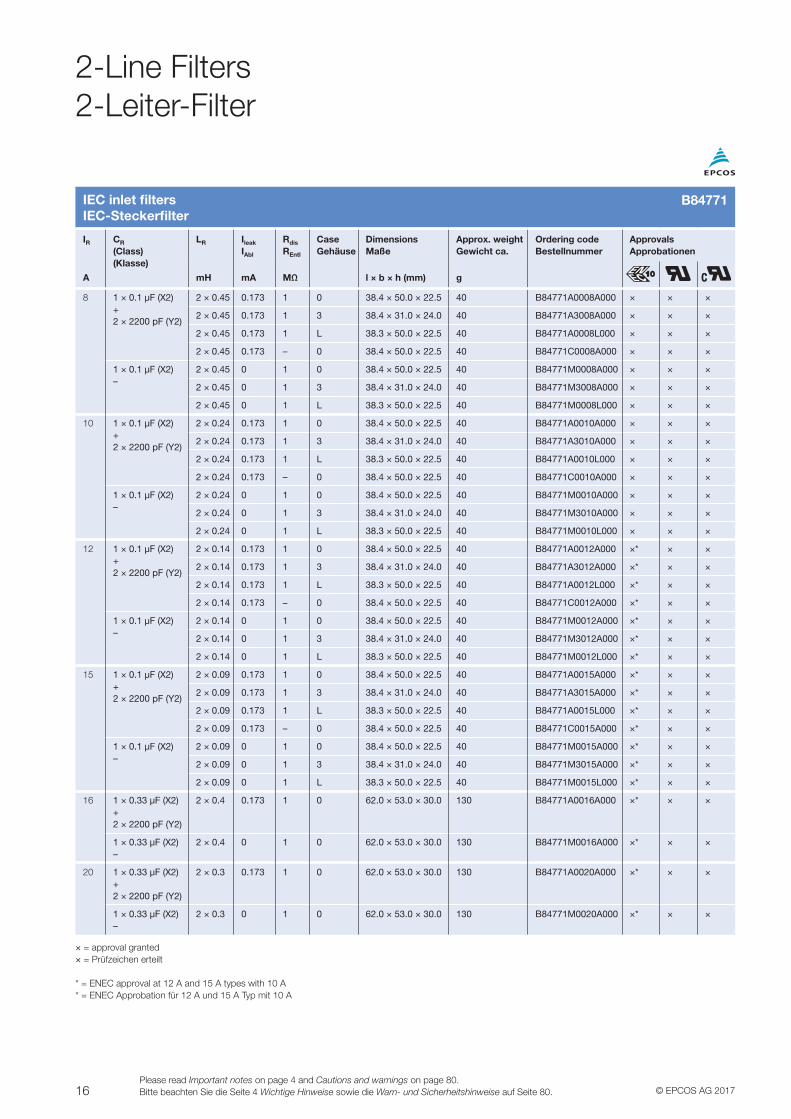
16 © EPCOS AG 2017Please read Important notes on page 4 and Cautions and warnings on page 80.Bitte beachten Sie die Seite 4 Wichtige Hinweise sowie die Warn- und Sicherheitshinweise auf Seite 80.
2-Line Filters2-Leiter-Filter
IEC inlet filtersIEC-Steckerfilter
IR CR
(Class)(Klasse)
LR Ileak
IAbl
Rdis
REntl
CaseGehäuse
DimensionsMaße
Approx. weightGewicht ca.
Ordering codeBestellnummer
ApprovalsApprobationen
A mH mA MΩ l × b × h (mm) g
8 1 × 0.1 μF (X2) +2 × 2200 pF (Y2)
2 × 0.45 0.173 1 0 38.4 × 50.0 × 22.5 40 B84771A0008A000 × × ×
2 × 0.45 0.173 1 3 38.4 × 31.0 × 24.0 40 B84771A3008A000 × × ×
2 × 0.45 0.173 1 L 38.3 × 50.0 × 22.5 40 B84771A0008L000 × × ×
2 × 0.45 0.173 – 0 38.4 × 50.0 × 22.5 40 B84771C0008A000 × × ×
1 × 0.1 μF (X2)–
2 × 0.45 0 1 0 38.4 × 50.0 × 22.5 40 B84771M0008A000 × × ×
2 × 0.45 0 1 3 38.4 × 31.0 × 24.0 40 B84771M3008A000 × × ×
2 × 0.45 0 1 L 38.3 × 50.0 × 22.5 40 B84771M0008L000 × × ×
10 1 × 0.1 μF (X2) +2 × 2200 pF (Y2)
2 × 0.24 0.173 1 0 38.4 × 50.0 × 22.5 40 B84771A0010A000 × × ×
2 × 0.24 0.173 1 3 38.4 × 31.0 × 24.0 40 B84771A3010A000 × × ×
2 × 0.24 0.173 1 L 38.3 × 50.0 × 22.5 40 B84771A0010L000 × × ×
2 × 0.24 0.173 – 0 38.4 × 50.0 × 22.5 40 B84771C0010A000 × × ×
1 × 0.1 μF (X2)–
2 × 0.24 0 1 0 38.4 × 50.0 × 22.5 40 B84771M0010A000 × × ×
2 × 0.24 0 1 3 38.4 × 31.0 × 24.0 40 B84771M3010A000 × × ×
2 × 0.24 0 1 L 38.3 × 50.0 × 22.5 40 B84771M0010L000 × × ×
12 1 × 0.1 μF (X2) +2 × 2200 pF (Y2)
2 × 0.14 0.173 1 0 38.4 × 50.0 × 22.5 40 B84771A0012A000 ×* × ×
2 × 0.14 0.173 1 3 38.4 × 31.0 × 24.0 40 B84771A3012A000 ×* × ×
2 × 0.14 0.173 1 L 38.3 × 50.0 × 22.5 40 B84771A0012L000 ×* × ×
2 × 0.14 0.173 – 0 38.4 × 50.0 × 22.5 40 B84771C0012A000 ×* × ×
1 × 0.1 μF (X2)–
2 × 0.14 0 1 0 38.4 × 50.0 × 22.5 40 B84771M0012A000 ×* × ×
2 × 0.14 0 1 3 38.4 × 31.0 × 24.0 40 B84771M3012A000 ×* × ×
2 × 0.14 0 1 L 38.3 × 50.0 × 22.5 40 B84771M0012L000 ×* × ×
15 1 × 0.1 μF (X2) +2 × 2200 pF (Y2)
2 × 0.09 0.173 1 0 38.4 × 50.0 × 22.5 40 B84771A0015A000 ×* × ×
2 × 0.09 0.173 1 3 38.4 × 31.0 × 24.0 40 B84771A3015A000 ×* × ×
2 × 0.09 0.173 1 L 38.3 × 50.0 × 22.5 40 B84771A0015L000 ×* × ×
2 × 0.09 0.173 – 0 38.4 × 50.0 × 22.5 40 B84771C0015A000 ×* × ×
1 × 0.1 μF (X2)–
2 × 0.09 0 1 0 38.4 × 50.0 × 22.5 40 B84771M0015A000 ×* × ×
2 × 0.09 0 1 3 38.4 × 31.0 × 24.0 40 B84771M3015A000 ×* × ×
2 × 0.09 0 1 L 38.3 × 50.0 × 22.5 40 B84771M0015L000 ×* × ×
16 1 × 0.33 µF (X2)+2 × 2200 pF (Y2)
2 × 0.4 0.173 1 0 62.0 × 53.0 × 30.0 130 B84771A0016A000 ×* × ×
1 × 0.33 µF (X2)–
2 × 0.4 0 1 0 62.0 × 53.0 × 30.0 130 B84771M0016A000 ×* × ×
20 1 × 0.33 µF (X2)+2 × 2200 pF (Y2)
2 × 0.3 0.173 1 0 62.0 × 53.0 × 30.0 130 B84771A0020A000 ×* × ×
1 × 0.33 µF (X2)–
2 × 0.3 0 1 0 62.0 × 53.0 × 30.0 130 B84771M0020A000 ×* × ×
× = approval granted× = Prüfzeichen erteilt
* = ENEC approval at 12 A and 15 A types with 10 A* = ENEC Approbation für 12 A und 15 A Typ mit 10 A
B84771
17© EPCOS AG 2017Please read Important notes on page 4 and Cautions and warnings on page 80.
Bitte beachten Sie die Seite 4 Wichtige Hinweise sowie die Warn- und Sicherheitshinweise auf Seite 80.
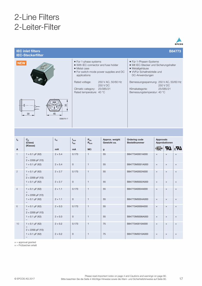
IEC inlet filtersIEC-Steckerfilter
VV For 1-phase systemsVV With IEC connector and fuse holderVV Metal caseVV For switch-mode power supplies and DC applications
Rated voltage: 250 V AC, 50/60 Hz 250 V DCClimatic category: 25/085/21Rated temperature: 40 °C
VV Für 1-Phasen-SystemeVV Mit IEC-Stecker und SicherungshalterVV MetallgehäuseVV VVFür Schaltnetzteile und DC-Anwendungen
Bemessungsspannung: 250 V AC, 50/60 Hz 250 V DCKlimakategorie: 25/085/21Bemessungstemperatur: 40 °C
39 46
35
SSB2701-7
IR CR
(Class)(Klasse)
LR Ileak
IAbl
Rdis
REntl
Approx. weightGewicht ca.
Ordering codeBestellnummer
ApprovalsApprobationen
A mH mA MΩ g
1 1 × 0.1 μF (X2) +2 × 2200 pF (Y2)
2 × 5.4 0.173 1 55 B84773A0001A000 × × ×
1 × 0.1 μF (X2)–
2 × 5.4 0 1 55 B84773M0001A000 × × ×
2 1 × 0.1 μF (X2) +2 × 2200 pF (Y2)
2 × 2.7 0.173 1 55 B84773A0002A000 × × ×
1 × 0.1 μF (X2)–
2 × 2.7 0 1 55 B84773M0002A000 × × ×
4 1 × 0.1 μF (X2) +2 × 2200 μF (Y2)
2 × 1.1 0.173 1 55 B84773A0004A000 × × ×
1 × 0.1 μF (X2)–
2 × 1.1 0 1 55 B84773M0004A000 × × ×
6 1 × 0.1 μF (X2) +2 × 2200 pF (Y2)
2 × 0.3 0.173 1 55 B84773A0006A000 × × ×
1 × 0.1 μF (X2)–
2 × 0.3 0 1 55 B84773M0006A000 × × ×
10 1 × 0.1 μF (X2) +2 × 2200 pF (Y2)
2 × 0.2 0.173 1 75 B84773A0010A000 × × ×
1 × 0.1 μF (X2)–
2 × 0.2 0 1 75 B84773M0010A000 × × ×
× = approval granted× = Prüfzeichen erteilt
B84773
NEW
2-Line Filters2-Leiter-Filter
18 © EPCOS AG 2017Please read Important notes on page 4 and Cautions and warnings on page 80.Bitte beachten Sie die Seite 4 Wichtige Hinweise sowie die Warn- und Sicherheitshinweise auf Seite 80.
2-Line Filters2-Leiter-Filter
IEC inlet filtersIEC-Steckerfilter
VV For 1-phase systemsVV With IEC connector, fuse holder and switchVV Metal caseVV For switch-mode power supplies and DC applications
Rated voltage: 250 V AC, 50/60 Hz 250 V DCClimatic category: 25/085/21Rated temperature: 40 °C
VV Für 1-Phasen-SystemeVV Mit IEC-Stecker, Sicherungshalter und SchalterVV MetallgehäuseVV Für Schaltnetzteile und DC-Anwendungen
Bemessungsspannung: 250 V AC, 50/60 Hz 250 V DCKlimakategorie: 25/085/21Bemessungstemperatur: 40 °C
38.1 50
65
SSB2702-F
IR CR
(Class)(Klasse)
LR Ileak
IAbl
Rdis
REntl
Approx. weightGewicht ca.
Ordering codeBestellnummer
ApprovalsApprobationen
A mH mA MΩ g
1 1 × 0.22 μF (X2) +2 × 2200 pF (Y2)
2 × 7.6 0.173 1 90 B84776A0001A000 × × ×
1 × 0.22 μF (X2)–
2 × 7.6 0 1 90 B84776M0001A000 × × ×
2 1 × 0.22 μF (X2) +2 × 2200 pF (Y2)
2 × 2.0 0.173 1 90 B84776A0002A000 × × ×
1 × 0.22 μF (X2)–
2 × 2.0 0 1 90 B84776M0002A000 × × ×
4 1 × 0.22 μF (X2) +2 × 2200 pF (Y2)
2 × 1.0 0.173 1 90 B84776A0004A000 × × ×
1 × 0.22 μF (X2)–
2 × 1.0 0 1 90 B84776M0004A000 × × ×
6 1 × 0.22 μF (X2) +2 × 2200 pF (Y2)
2 × 0.46 0.173 1 90 B84776A0006A000 × × ×
1 × 0.22 μF (X2)–
2 × 0.46 0 1 90 B84776M0006A000 × × ×
10 1 × 0.22 μF (X2) +2 × 2200 pF (Y2)
2 × 0.33 0.173 1 130 B84776A0010A000 × × ×
1 × 0.22 μF (X2)–
2 × 0.33 0 1 130 B84776M0010A000 × × ×
× = approval granted× = Prüfzeichen erteilt
B84776
NEW
19© EPCOS AG 2017Please read Important notes on page 4 and Cautions and warnings on page 80.
Bitte beachten Sie die Seite 4 Wichtige Hinweise sowie die Warn- und Sicherheitshinweise auf Seite 80.
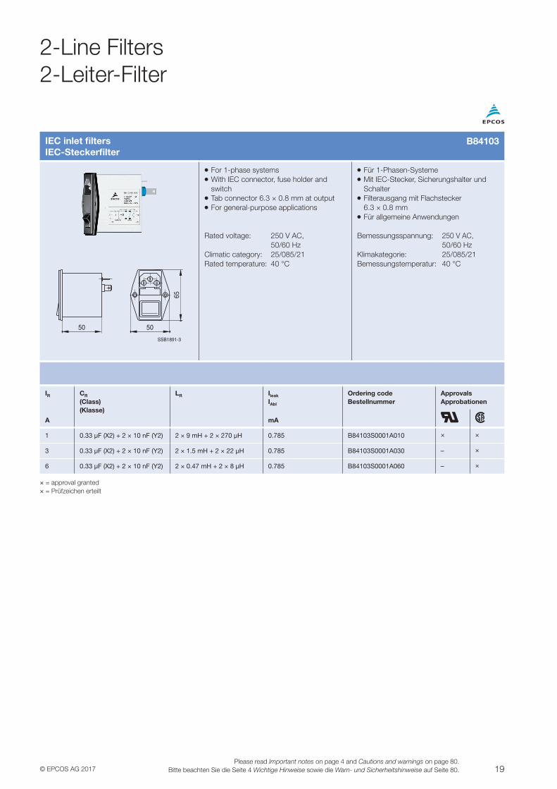
IEC inlet filtersIEC-Steckerfilter
VV For 1-phase systemsVV With IEC connector, fuse holder and switchVV Tab connector 6.3 × 0.8 mm at outputVV For general-purpose applications
Rated voltage: 250 V AC, 50/60 HzClimatic category: 25/085/21Rated temperature: 40 °C
VV Für 1-Phasen-SystemeVV Mit IEC-Stecker, Sicherungshalter und SchalterVV Filterausgang mit Flachstecker 6.3 × 0.8 mmVV Für allgemeine Anwendungen
Bemessungsspannung: 250 V AC, 50/60 HzKlimakategorie: 25/085/21Bemessungstemperatur: 40 °C
SSB1891-3
50 50
65
IR CR
(Class)(Klasse)
LR Ileak
IAbl
Ordering codeBestellnummer
ApprovalsApprobationen
A mA
1 0.33 μF (X2) + 2 × 10 nF (Y2) 2 × 9 mH + 2 × 270 μH 0.785 B84103S0001A010 × ×
3 0.33 μF (X2) + 2 × 10 nF (Y2) 2 × 1.5 mH + 2 × 22 μH 0.785 B84103S0001A030 – ×
6 0.33 μF (X2) + 2 × 10 nF (Y2) 2 × 0.47 mH + 2 × 8 μH 0.785 B84103S0001A060 – ×
× = approval granted× = Prüfzeichen erteilt
B84103
2-Line Filters2-Leiter-Filter
20 © EPCOS AG 2017Please read Important notes on page 4 and Cautions and warnings on page 80.Bitte beachten Sie die Seite 4 Wichtige Hinweise sowie die Warn- und Sicherheitshinweise auf Seite 80.
2-Line Filters2-Leiter-Filter
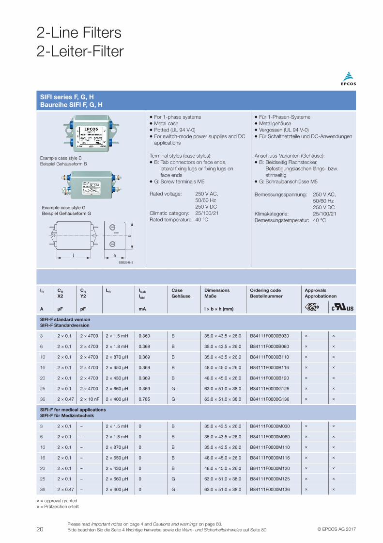
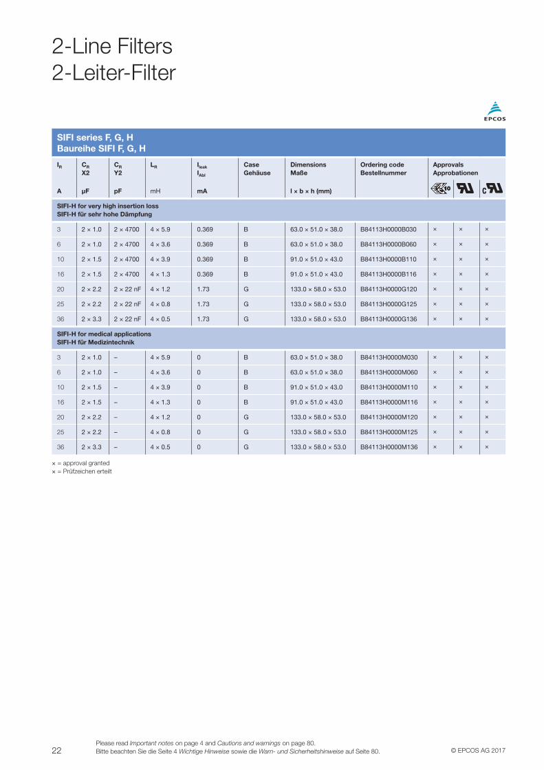
SIFI series F, G, HBaureihe SIFI F, G, H
VV For 1-phase systemsVV Metal caseVV Potted (UL 94 V-0)VV For switch-mode power supplies and DC applications
Terminal styles (case styles):VV B: Tab connectors on face ends, lateral fixing lugs or fixing lugs on face endsVV G: Screw terminals M5
Rated voltage: 250 V AC, 50/60 Hz 250 V DCClimatic category: 25/100/21Rated temperature: 40 °C
VV Für 1-Phasen-SystemeVV MetallgehäuseVV Vergossen (UL 94 V-0)VV Für Schaltnetzteile und DC-Anwendungen
Anschluss-Varianten (Gehäuse):VV B: Beidseitig Flachstecker, Befestigungslaschen längs- bzw. stirnseitigVV G: Schraubanschlüsse M5
Bemessungsspannung: 250 V AC, 50/60 Hz 250 V DCKlimakategorie: 25/100/21Bemessungstemperatur: 40 °C
Example case style BBeispiel Gehäuseform B
Example case style GBeispiel Gehäuseform G
SSB2248-S
h
b
IR CR
X2CR
Y2LR Ileak
IAbl
CaseGehäuse
DimensionsMaße
Ordering codeBestellnummer
ApprovalsApprobationen
A µF pF mA l × b × h (mm)
SIFI-F standard versionSIFI-F Standardversion
3 2 × 0.1 2 × 4700 2 × 1.5 mH 0.369 B 35.0 × 43.5 × 26.0 B84111F0000B030 × ×
6 2 × 0.1 2 × 4700 2 × 1.8 mH 0.369 B 35.0 × 43.5 × 26.0 B84111F0000B060 × ×
10 2 × 0.1 2 × 4700 2 × 870 μH 0.369 B 35.0 × 43.5 × 26.0 B84111F0000B110 × ×
16 2 × 0.1 2 × 4700 2 × 650 μH 0.369 B 48.0 × 45.0 × 26.0 B84111F0000B116 × ×
20 2 × 0.1 2 × 4700 2 × 430 μH 0.369 B 48.0 × 45.0 × 26.0 B84111F0000B120 × ×
25 2 × 0.1 2 × 4700 2 × 660 μH 0.369 G 63.0 × 51.0 × 38.0 B84111F0000G125 × ×
36 2 × 0.47 2 × 10 nF 2 × 400 μH 0.785 G 63.0 × 51.0 × 38.0 B84111F0000G136 × ×
SIFI-F for medical applicationsSIFI-F für Medizintechnik
3 2 × 0.1 – 2 × 1.5 mH 0 B 35.0 × 43.5 × 26.0 B84111F0000M030 × ×
6 2 × 0.1 – 2 × 1.8 mH 0 B 35.0 × 43.5 × 26.0 B84111F0000M060 × ×
10 2 × 0.1 – 2 × 870 μH 0 B 35.0 × 43.5 × 26.0 B84111F0000M110 × ×
16 2 × 0.1 – 2 × 650 μH 0 B 48.0 × 45.0 × 26.0 B84111F0000M116 × ×
20 2 × 0.1 – 2 × 430 μH 0 B 48.0 × 45.0 × 26.0 B84111F0000M120 × ×
25 2 × 0.1 – 2 × 660 μH 0 G 63.0 × 51.0 × 38.0 B84111F0000M125 × ×
36 2 × 0.47 – 2 × 400 μH 0 G 63.0 × 51.0 × 38.0 B84111F0000M136 × ×
× = approval granted× = Prüfzeichen erteilt
21© EPCOS AG 2017Please read Important notes on page 4 and Cautions and warnings on page 80.
Bitte beachten Sie die Seite 4 Wichtige Hinweise sowie die Warn- und Sicherheitshinweise auf Seite 80.
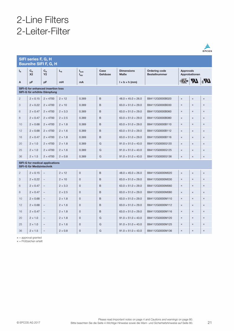
SIFI series F, G, HBaureihe SIFI F, G, H
IR CR
X2CR
Y2LR Ileak
IAbl
CaseGehäuse
DimensionsMaße
Ordering codeBestellnummer
ApprovalsApprobationen
A µF pF mH mA l × b × h (mm)
SIFI-G for enhanced insertion lossSIFI-G für erhöhte Dämpfung
2 2 × 0.15 2 × 4700 2 × 12 0.369 B 48.0 × 45.0 × 26.0 B84112G0000B020 × × ×
3 2 × 0.22 2 × 4700 2 × 10 0.369 B 63.0 × 51.0 × 29.0 B84112G0000B030 × × ×
6 2 × 0.47 2 × 4700 2 × 3.3 0.369 B 63.0 × 51.0 × 29.0 B84112G0000B060 × × ×
8 2 × 0.47 2 × 4700 2 × 2.5 0.369 B 63.0 × 51.0 × 29.0 B84112G0000B080 × × ×
10 2 × 0.68 2 × 4700 2 × 1.8 0.369 B 63.0 × 51.0 × 29.0 B84112G0000B110 × × ×
12 2 × 0.68 2 × 4700 2 × 1.6 0.369 B 63.0 × 51.0 × 29.0 B84112G0000B112 × × ×
16 2 × 0.47 2 × 4700 2 × 1.8 0.369 B 63.0 × 51.0 × 29.0 B84112G0000B116 × × ×
20 2 × 1.0 2 × 4700 2 × 1.8 0.369 G 91.0 × 51.0 × 43.0 B84112G0000G120 × × ×
25 2 × 1.0 2 × 4700 2 × 1.6 0.369 G 91.0 × 51.0 × 43.0 B84112G0000G125 × × ×
36 2 × 1.5 2 × 4700 2 × 0.8 0.369 G 91.0 × 51.0 × 43.0 B84112G0000G136 × × ×
SIFI-G for medical applicationsSIFI-G für Medizintechnik
2 2 × 0.15 – 2 × 12 0 B 48.0 × 45.0 × 26.0 B84112G0000M020 × × ×
3 2 × 0.22 – 2 × 10 0 B 63.0 × 51.0 × 29.0 B84112G0000M030 × × ×
6 2 × 0.47 – 2 × 3.3 0 B 63.0 × 51.0 × 29.0 B84112G0000M060 × × ×
8 2 × 0.47 – 2 × 2.5 0 B 63.0 × 51.0 × 29.0 B84112G0000M080 × × ×
10 2 × 0.68 – 2 × 1.8 0 B 63.0 × 51.0 × 29.0 B84112G0000M110 × × ×
12 2 × 0.68 – 2 × 1.6 0 B 63.0 × 51.0 × 29.0 B84112G0000M112 × × ×
16 2 × 0.47 – 2 × 1.8 0 B 63.0 × 51.0 × 29.0 B84112G0000M116 × × ×
20 2 × 1.0 – 2 × 1.8 0 G 91.0 × 51.0 × 43.0 B84112G0000M120 × × ×
25 2 × 1.0 – 2 × 1.6 0 G 91.0 × 51.0 × 43.0 B84112G0000M125 × × ×
36 2 × 1.5 – 2 × 0.8 0 G 91.0 × 51.0 × 43.0 B84112G0000M136 × × ×
× = approval granted× = Prüfzeichen erteilt
2-Line Filters2-Leiter-Filter
22 © EPCOS AG 2017Please read Important notes on page 4 and Cautions and warnings on page 80.Bitte beachten Sie die Seite 4 Wichtige Hinweise sowie die Warn- und Sicherheitshinweise auf Seite 80.
2-Line Filters2-Leiter-Filter
SIFI series F, G, HBaureihe SIFI F, G, H
IR CR
X2CR
Y2LR Ileak
IAbl
CaseGehäuse
DimensionsMaße
Ordering codeBestellnummer
ApprovalsApprobationen
A µF pF mH mA l × b × h (mm)
SIFI-H for very high insertion lossSIFI-H für sehr hohe Dämpfung
3 2 × 1.0 2 × 4700 4 × 5.9 0.369 B 63.0 × 51.0 × 38.0 B84113H0000B030 × × ×
6 2 × 1.0 2 × 4700 4 × 3.6 0.369 B 63.0 × 51.0 × 38.0 B84113H0000B060 × × ×
10 2 × 1.5 2 × 4700 4 × 3.9 0.369 B 91.0 × 51.0 × 43.0 B84113H0000B110 × × ×
16 2 × 1.5 2 × 4700 4 × 1.3 0.369 B 91.0 × 51.0 × 43.0 B84113H0000B116 × × ×
20 2 × 2.2 2 × 22 nF 4 × 1.2 1.73 G 133.0 × 58.0 × 53.0 B84113H0000G120 × × ×
25 2 × 2.2 2 × 22 nF 4 × 0.8 1.73 G 133.0 × 58.0 × 53.0 B84113H0000G125 × × ×
36 2 × 3.3 2 × 22 nF 4 × 0.5 1.73 G 133.0 × 58.0 × 53.0 B84113H0000G136 × × ×
SIFI-H for medical applicationsSIFI-H für Medizintechnik
3 2 × 1.0 – 4 × 5.9 0 B 63.0 × 51.0 × 38.0 B84113H0000M030 × × ×
6 2 × 1.0 – 4 × 3.6 0 B 63.0 × 51.0 × 38.0 B84113H0000M060 × × ×
10 2 × 1.5 – 4 × 3.9 0 B 91.0 × 51.0 × 43.0 B84113H0000M110 × × ×
16 2 × 1.5 – 4 × 1.3 0 B 91.0 × 51.0 × 43.0 B84113H0000M116 × × ×
20 2 × 2.2 – 4 × 1.2 0 G 133.0 × 58.0 × 53.0 B84113H0000M120 × × ×
25 2 × 2.2 – 4 × 0.8 0 G 133.0 × 58.0 × 53.0 B84113H0000M125 × × ×
36 2 × 3.3 – 4 × 0.5 0 G 133.0 × 58.0 × 53.0 B84113H0000M136 × × ×
× = approval granted× = Prüfzeichen erteilt
23© EPCOS AG 2017Please read Important notes on page 4 and Cautions and warnings on page 80.
Bitte beachten Sie die Seite 4 Wichtige Hinweise sowie die Warn- und Sicherheitshinweise auf Seite 80.
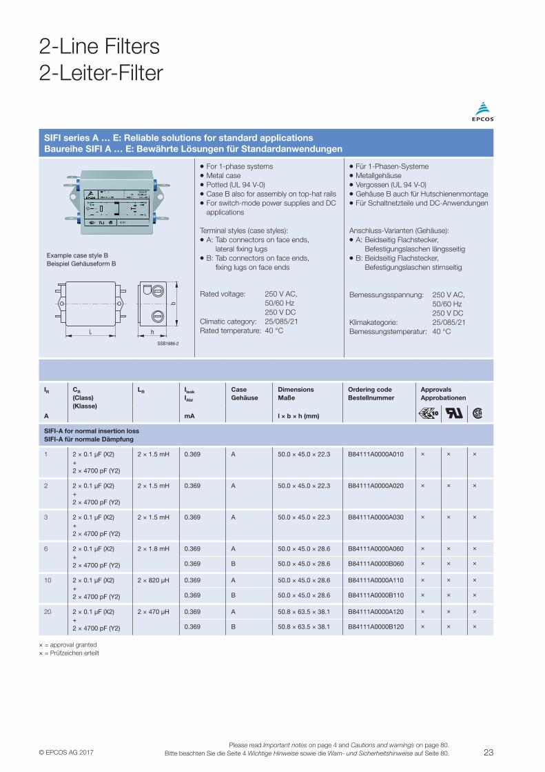
SIFI series A … E: Reliable solutions for standard applicationsBaureihe SIFI A … E: Bewährte Lösungen für Standardanwendungen
VV For 1-phase systemsVV Metal caseVV Potted (UL 94 V-0)VV Case B also for assembly on top-hat railsVV For switch-mode power supplies and DC applications
Terminal styles (case styles):VV A: Tab connectors on face ends, lateral fixing lugsVV B: Tab connectors on face ends, fixing lugs on face ends
Rated voltage: 250 V AC, 50/60 Hz 250 V DCClimatic category: 25/085/21Rated temperature: 40 °C
VV Für 1-Phasen-SystemeVV MetallgehäuseVV Vergossen (UL 94 V-0)VV Gehäuse B auch für HutschienenmontageVV Für Schaltnetzteile und DC-Anwendungen
Anschluss-Varianten (Gehäuse):VV A: Beidseitig Flachstecker, Befestigungslaschen längsseitigVV B: Beidseitig Flachstecker, Befestigungslaschen stirnseitig
Bemessungsspannung: 250 V AC, 50/60 Hz 250 V DCKlimakategorie: 25/085/21Bemessungstemperatur: 40 °C
Example case style BBeispiel Gehäuseform B
SSB1886-2
h
b
IR CR
(Class)(Klasse)
LR Ileak
IAbl
CaseGehäuse
DimensionsMaße
Ordering codeBestellnummer
ApprovalsApprobationen
A mA l × b × h (mm)
SIFI-A for normal insertion lossSIFI-A für normale Dämpfung
1 2 × 0.1 μF (X2)+2 × 4700 pF (Y2)
2 × 1.5 mH 0.369 A 50.0 × 45.0 × 22.3 B84111A0000A010 × × ×
2 2 × 0.1 μF (X2)+2 × 4700 pF (Y2)
2 × 1.5 mH 0.369 A 50.0 × 45.0 × 22.3 B84111A0000A020 × × ×
3 2 × 0.1 μF (X2)+2 × 4700 pF (Y2)
2 × 1.5 mH 0.369 A 50.0 × 45.0 × 22.3 B84111A0000A030 × × ×
6 2 × 0.1 μF (X2)+2 × 4700 pF (Y2)
2 × 1.8 mH 0.369 A 50.0 × 45.0 × 28.6 B84111A0000A060 × × ×
0.369 B 50.0 × 45.0 × 28.6 B84111A0000B060 × × ×
10 2 × 0.1 μF (X2)+2 × 4700 pF (Y2)
2 × 820 μH 0.369 A 50.0 × 45.0 × 28.6 B84111A0000A110 × × ×
0.369 B 50.0 × 45.0 × 28.6 B84111A0000B110 × × ×
20 2 × 0.1 μF (X2)+2 × 4700 pF (Y2)
2 × 470 μH 0.369 A 50.8 × 63.5 × 38.1 B84111A0000A120 × × ×
0.369 B 50.8 × 63.5 × 38.1 B84111A0000B120 × × ×
× = approval granted× = Prüfzeichen erteilt
2-Line Filters2-Leiter-Filter
24 © EPCOS AG 2017Please read Important notes on page 4 and Cautions and warnings on page 80.Bitte beachten Sie die Seite 4 Wichtige Hinweise sowie die Warn- und Sicherheitshinweise auf Seite 80.
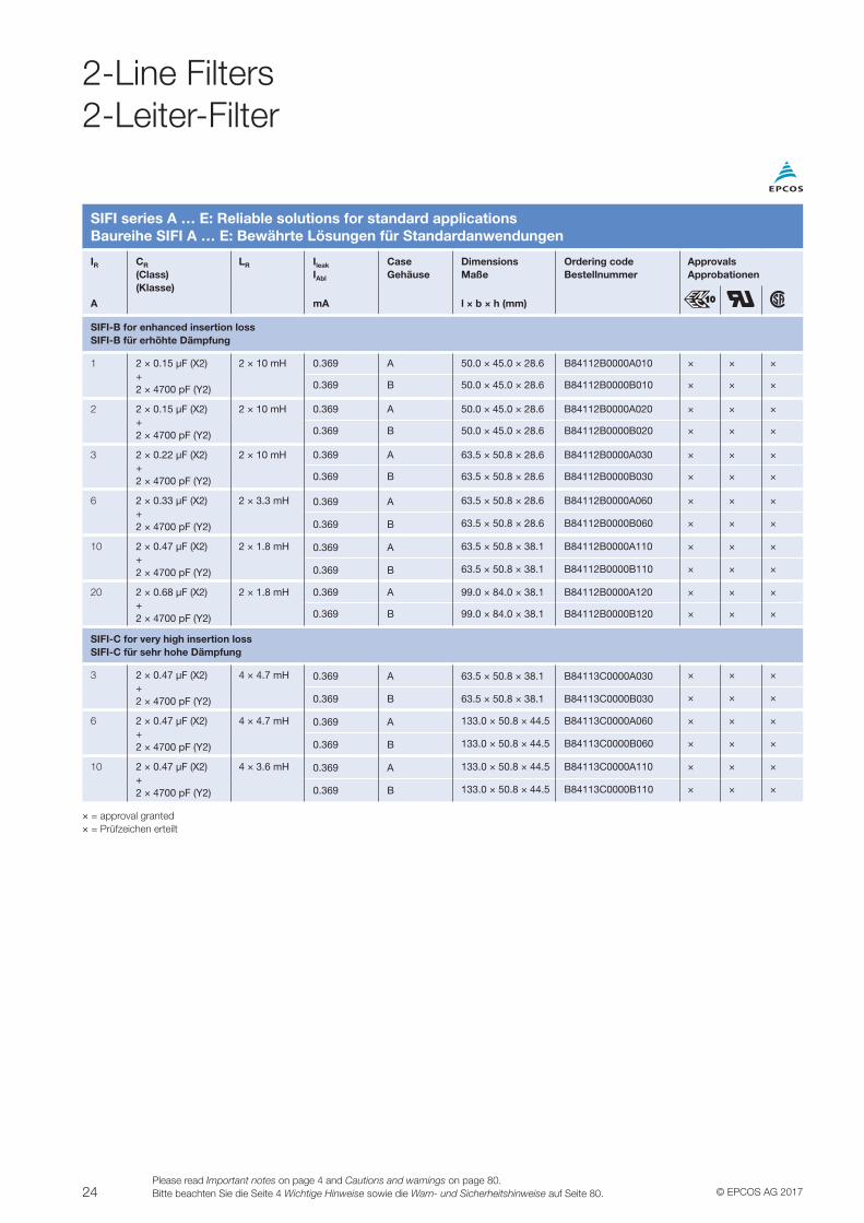
SIFI series A … E: Reliable solutions for standard applicationsBaureihe SIFI A … E: Bewährte Lösungen für Standardanwendungen
IR CR
(Class)(Klasse)
LR Ileak
IAbl
CaseGehäuse
DimensionsMaße
Ordering codeBestellnummer
ApprovalsApprobationen
A mA l × b × h (mm)
SIFI-B for enhanced insertion lossSIFI-B für erhöhte Dämpfung
1 2 × 0.15 μF (X2)+2 × 4700 pF (Y2)
2 × 10 mH 0.369 A 50.0 × 45.0 × 28.6 B84112B0000A010 × × ×
0.369 B 50.0 × 45.0 × 28.6 B84112B0000B010 × × ×
2 2 × 0.15 μF (X2)+2 × 4700 pF (Y2)
2 × 10 mH 0.369 A 50.0 × 45.0 × 28.6 B84112B0000A020 × × ×
0.369 B 50.0 × 45.0 × 28.6 B84112B0000B020 × × ×
3 2 × 0.22 μF (X2)+2 × 4700 pF (Y2)
2 × 10 mH 0.369 A 63.5 × 50.8 × 28.6 B84112B0000A030 × × ×
0.369 B 63.5 × 50.8 × 28.6 B84112B0000B030 × × ×
6 2 × 0.33 μF (X2)+2 × 4700 pF (Y2)
2 × 3.3 mH 0.369 A 63.5 × 50.8 × 28.6 B84112B0000A060 × × ×
0.369 B 63.5 × 50.8 × 28.6 B84112B0000B060 × × ×
10 2 × 0.47 μF (X2)+2 × 4700 pF (Y2)
2 × 1.8 mH 0.369 A 63.5 × 50.8 × 38.1 B84112B0000A110 × × ×
0.369 B 63.5 × 50.8 × 38.1 B84112B0000B110 × × ×
20 2 × 0.68 μF (X2)+2 × 4700 pF (Y2)
2 × 1.8 mH 0.369 A 99.0 × 84.0 × 38.1 B84112B0000A120 × × ×
0.369 B 99.0 × 84.0 × 38.1 B84112B0000B120 × × ×
SIFI-C for very high insertion lossSIFI-C für sehr hohe Dämpfung
3 2 × 0.47 μF (X2)+2 × 4700 pF (Y2)
4 × 4.7 mH 0.369 A 63.5 × 50.8 × 38.1 B84113C0000A030 × × ×
0.369 B 63.5 × 50.8 × 38.1 B84113C0000B030 × × ×
6 2 × 0.47 μF (X2)+2 × 4700 pF (Y2)
4 × 4.7 mH 0.369 A 133.0 × 50.8 × 44.5 B84113C0000A060 × × ×
0.369 B 133.0 × 50.8 × 44.5 B84113C0000B060 × × ×
10 2 × 0.47 μF (X2)+2 × 4700 pF (Y2)
4 × 3.6 mH 0.369 A 133.0 × 50.8 × 44.5 B84113C0000A110 × × ×
0.369 B 133.0 × 50.8 × 44.5 B84113C0000B110 × × ×
× = approval granted× = Prüfzeichen erteilt
2-Line Filters2-Leiter-Filter
25© EPCOS AG 2017Please read Important notes on page 4 and Cautions and warnings on page 80.
Bitte beachten Sie die Seite 4 Wichtige Hinweise sowie die Warn- und Sicherheitshinweise auf Seite 80.
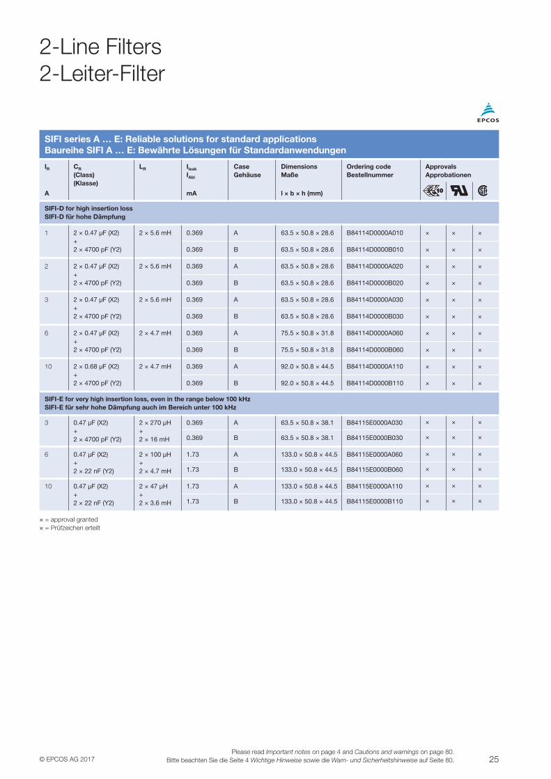
SIFI series A … E: Reliable solutions for standard applicationsBaureihe SIFI A … E: Bewährte Lösungen für Standardanwendungen
IR CR
(Class)(Klasse)
LR Ileak
IAbl
CaseGehäuse
DimensionsMaße
Ordering codeBestellnummer
ApprovalsApprobationen
A mA l × b × h (mm)
SIFI-D for high insertion lossSIFI-D für hohe Dämpfung
1 2 × 0.47 μF (X2)+2 × 4700 pF (Y2)
2 × 5.6 mH 0.369 A 63.5 × 50.8 × 28.6 B84114D0000A010 × × ×
0.369 B 63.5 × 50.8 × 28.6 B84114D0000B010 × × ×
2 2 × 0.47 μF (X2)+2 × 4700 pF (Y2)
2 × 5.6 mH 0.369 A 63.5 × 50.8 × 28.6 B84114D0000A020 × × ×
0.369 B 63.5 × 50.8 × 28.6 B84114D0000B020 × × ×
3 2 × 0.47 μF (X2)+2 × 4700 pF (Y2)
2 × 5.6 mH 0.369 A 63.5 × 50.8 × 28.6 B84114D0000A030 × × ×
0.369 B 63.5 × 50.8 × 28.6 B84114D0000B030 × × ×
6 2 × 0.47 μF (X2)+2 × 4700 pF (Y2)
2 × 4.7 mH 0.369 A 75.5 × 50.8 × 31.8 B84114D0000A060 × × ×
0.369 B 75.5 × 50.8 × 31.8 B84114D0000B060 × × ×
10 2 × 0.68 μF (X2)+2 × 4700 pF (Y2)
2 × 4.7 mH 0.369 A 92.0 × 50.8 × 44.5 B84114D0000A110 × × ×
0.369 B 92.0 × 50.8 × 44.5 B84114D0000B110 × × ×
SIFI-E for very high insertion loss, even in the range below 100 kHzSIFI-E für sehr hohe Dämpfung auch im Bereich unter 100 kHz
3 0.47 μF (X2)+2 × 4700 pF (Y2)
2 × 270 μH+2 × 16 mH
0.369 A 63.5 × 50.8 × 38.1 B84115E0000A030 × × ×
0.369 B 63.5 × 50.8 × 38.1 B84115E0000B030 × × ×
6 0.47 μF (X2)+2 × 22 nF (Y2)
2 × 100 μH+2 × 4.7 mH
1.73 A 133.0 × 50.8 × 44.5 B84115E0000A060 × × ×
1.73 B 133.0 × 50.8 × 44.5 B84115E0000B060 × × ×
10 0.47 μF (X2)+2 × 22 nF (Y2)
2 × 47 μH+2 × 3.6 mH
1.73 A 133.0 × 50.8 × 44.5 B84115E0000A110 × × ×
1.73 B 133.0 × 50.8 × 44.5 B84115E0000B110 × × ×
× = approval granted× = Prüfzeichen erteilt
2-Line Filters2-Leiter-Filter
26 © EPCOS AG 2017Please read Important notes on page 4 and Cautions and warnings on page 80.Bitte beachten Sie die Seite 4 Wichtige Hinweise sowie die Warn- und Sicherheitshinweise auf Seite 80.
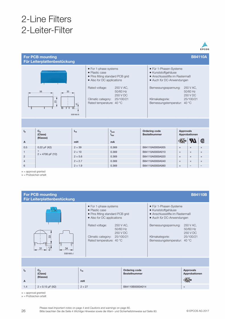
2-Line Filters2-Leiter-Filter
For PCB mountingFür Leiterplattenbestückung
VV For 1-phase systemsVV Plastic caseVV Pins fitting standard PCB gridVV Also for DC applications
Rated voltage: 250 V AC, 50/60 Hz 250 V DCClimatic category: 25/100/21Rated temperature: 40 °C
VV Für 1-Phasen-SystemeVV KunststoffgehäuseVV Anschlussstifte im RastermaßVV Auch für DC-Anwendungen
Bemessungsspannung: 250 V AC, 50/60 Hz 250 V DCKlimakategorie: 25/100/21Bemessungstemperatur: 40 °C
SSB1893-J
3431
334±
1
IR CR
(Class)(Klasse)
LR Ordering codeBestellnummer
ApprovalsApprobationen
A mH
1.4 2 × 0.15 μF (X2) 2 × 27 B84110B0000A014 ×
× = approval granted× = Prüfzeichen erteilt
For PCB mountingFür Leiterplattenbestückung
VV For 1-phase systemsVV Plastic caseVV Pins fitting standard PCB gridVV Also for DC applications
Rated voltage: 250 V AC, 50/60 Hz 250 V DCClimatic category: 25/100/21Rated temperature: 40 °C
VV Für 1-Phasen-SystemeVV KunststoffgehäuseVV Anschlussstifte im RastermaßVV Auch für DC-Anwendungen
Bemessungsspannung: 250 V AC, 50/60 Hz 250 V DCKlimakategorie: 25/100/21Bemessungstemperatur: 40 °C
SSB1892-B
30
23
56
41
IR CR
(Class)(Klasse)
LR Ileak
IAbl
Ordering codeBestellnummer
ApprovalsApprobationen
A mH mA
0.5 0.22 μF (X2) + 2 × 4700 pF (Y2)
2 × 39 0.369 B84110A0000A005 × × ×
1 2 × 10 0.369 B84110A0000A010 × × ×
2 2 × 5.6 0.369 B84110A0000A020 × × ×
4 2 × 2.7 0.369 B84110A0000A040 × × ×
6 2 × 1.9 0.369 B84110A0000A060 × – –
× = approval granted× = Prüfzeichen erteilt
B84110A
B84110B
27© EPCOS AG 2017Please read Important notes on page 4 and Cautions and warnings on page 80.
Bitte beachten Sie die Seite 4 Wichtige Hinweise sowie die Warn- und Sicherheitshinweise auf Seite 80.
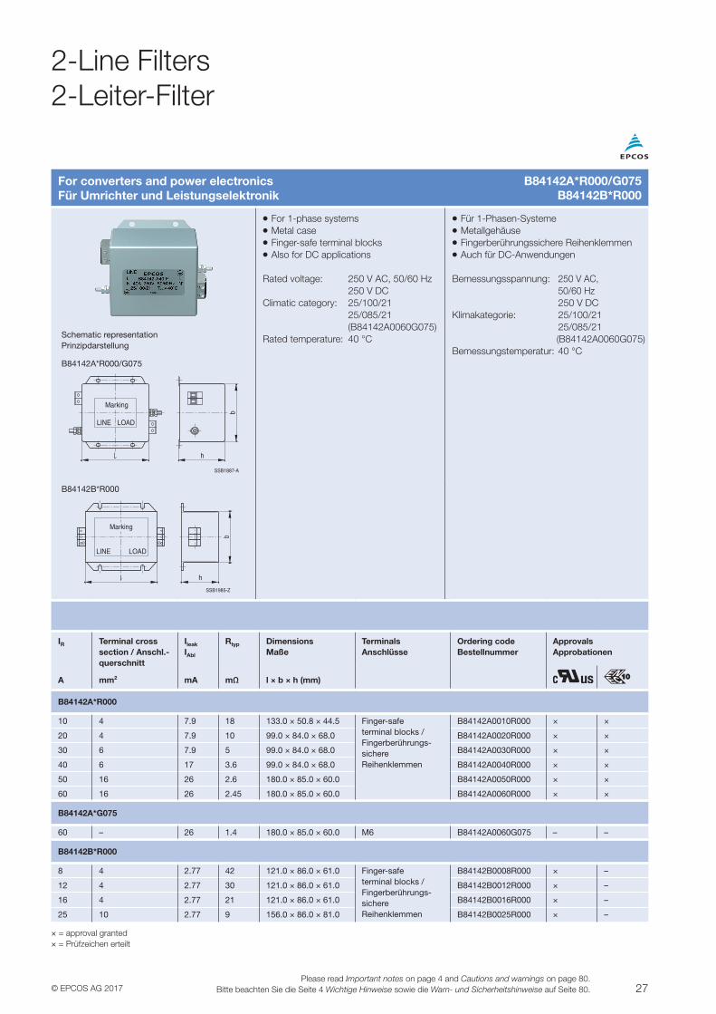
For converters and power electronicsFür Umrichter und Leistungselektronik
VV For 1-phase systemsVV Metal caseVV Finger-safe terminal blocksVV Also for DC applications
Rated voltage: 250 V AC, 50/60 Hz 250 V DCClimatic category: 25/100/21 25/085/21 (B84142A0060G075)Rated temperature: 40 °C
VV Für 1-Phasen-SystemeVV MetallgehäuseVV Fingerberührungssichere ReihenklemmenVV Auch für DC-Anwendungen
Bemessungsspannung: 250 V AC, 50/60 Hz 250 V DCKlimakategorie: 25/100/21 25/085/21 (B84142A0060G075)Bemessungstemperatur: 40 °C
Schematic representationPrinzipdarstellung
B84142A*R000/G075
SSB1887-A
b
h
LINE LOAD
Marking
B84142B*R000
SSB1985-Z
Marking
LOADLINE
b
h
IR Terminal crosssection / Anschl.-querschnitt
Ileak
IAbl
Rtyp DimensionsMaße
TerminalsAnschlüsse
Ordering codeBestellnummer
ApprovalsApprobationen
A mm2 mA mΩ l × b × h (mm)
B84142A*R000
10 4 7.9 18 133.0 × 50.8 × 44.5 Finger-safe terminal blocks / Fingerberührungs- sichere Reihenklemmen
B84142A0010R000 × ×
20 4 7.9 10 99.0 × 84.0 × 68.0 B84142A0020R000 × ×
30 6 7.9 5 99.0 × 84.0 × 68.0 B84142A0030R000 × ×
40 6 17 3.6 99.0 × 84.0 × 68.0 B84142A0040R000 × ×
50 16 26 2.6 180.0 × 85.0 × 60.0 B84142A0050R000 × ×
60 16 26 2.45 180.0 × 85.0 × 60.0 B84142A0060R000 × ×
B84142A*G075
60 – 26 1.4 180.0 × 85.0 × 60.0 M6 B84142A0060G075 – –
B84142B*R000
8 4 2.77 42 121.0 × 86.0 × 61.0 Finger-safe terminal blocks / Fingerberührungs- sichere Reihenklemmen
B84142B0008R000 × –
12 4 2.77 30 121.0 × 86.0 × 61.0 B84142B0012R000 × –
16 4 2.77 21 121.0 × 86.0 × 61.0 B84142B0016R000 × –
25 10 2.77 9 156.0 × 86.0 × 81.0 B84142B0025R000 × –
× = approval granted× = Prüfzeichen erteilt
B84142A*R000/G075B84142B*R000
2-Line Filters2-Leiter-Filter
28 © EPCOS AG 2017Please read Important notes on page 4 and Cautions and warnings on page 80.Bitte beachten Sie die Seite 4 Wichtige Hinweise sowie die Warn- und Sicherheitshinweise auf Seite 80.
2-Line Filters2-Leiter-Filter
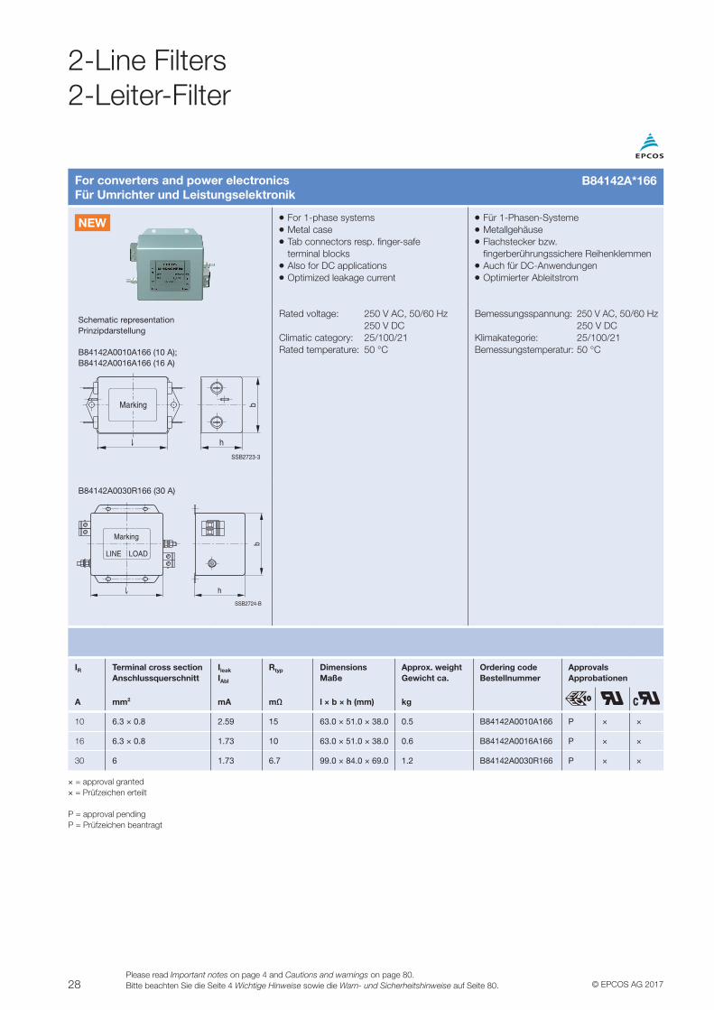
For converters and power electronicsFür Umrichter und Leistungselektronik
VV For 1-phase systemsVV Metal caseVV Tab connectors resp. finger-safe terminal blocksVV Also for DC applicationsVV Optimized leakage current
Rated voltage: 250 V AC, 50/60 Hz 250 V DCClimatic category: 25/100/21Rated temperature: 50 °C
VV Für 1-Phasen-SystemeVV MetallgehäuseVV Flachstecker bzw. fingerberührungssichere ReihenklemmenVV Auch für DC-AnwendungenVV Optimierter Ableitstrom
Bemessungsspannung: 250 V AC, 50/60 Hz 250 V DCKlimakategorie: 25/100/21Bemessungstemperatur: 50 °C
Schematic representationPrinzipdarstellung
B84142A0010A166 (10 A); B84142A0016A166 (16 A)
h
bMarking
SSB2723-3
B84142A0030R166 (30 A)
h
b
SSB2724-B
Marking
LINE LOAD
IR Terminal cross sectionAnschlussquerschnitt
Ileak
IAbl
Rtyp DimensionsMaße
Approx. weightGewicht ca.
Ordering codeBestellnummer
ApprovalsApprobationen
A mm2 mA mΩ l × b × h (mm) kg
10 6.3 × 0.8 2.59 15 63.0 × 51.0 × 38.0 0.5 B84142A0010A166 P × ×
16 6.3 × 0.8 1.73 10 63.0 × 51.0 × 38.0 0.6 B84142A0016A166 P × ×
30 6 1.73 6.7 99.0 × 84.0 × 69.0 1.2 B84142A0030R166 P × ×
× = approval granted× = Prüfzeichen erteilt
P = approval pendingP = Prüfzeichen beantragt
B84142A*166
NEW
29© EPCOS AG 2017Please read Important notes on page 4 and Cautions and warnings on page 80.
Bitte beachten Sie die Seite 4 Wichtige Hinweise sowie die Warn- und Sicherheitshinweise auf Seite 80.
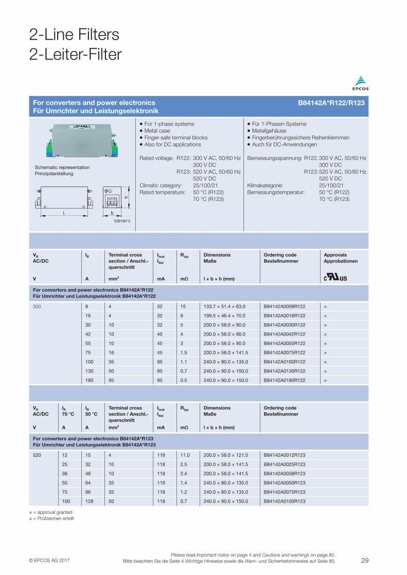
For converters and power electronicsFür Umrichter und Leistungselektronik
VV For 1-phase systemsVV Metal caseVV Finger-safe terminal blocksVV Also for DC applications
Rated voltage: R122: 300 V AC, 50/60 Hz 300 V DC R123: 520 V AC, 50/60 Hz 520 V DCClimatic category: 25/100/21Rated temperature: 50 °C (R122) 70 °C (R123)
VV Für 1-Phasen-SystemeVV MetallgehäuseVV Fingerberührungssichere ReihenklemmenVV Auch für DC-Anwendungen
Bemessungsspannung: R122: 300 V AC, 50/60 Hz 300 V DC R123: 520 V AC, 50/60 Hz 520 V DCKlimakategorie: 25/100/21Bemessungstemperatur: 50 °C (R122) 70 °C (R123)
Schematic representationPrinzipdarstellung
SSB1967-2
b
h
VR
AC/DCIR Terminal cross
section / Anschl.-querschnitt
Ileak
IAbl
Rtyp DimensionsMaße
Ordering codeBestellnummer
ApprovalsApprobationen
V A mm2 mA mΩ l × b × h (mm)
For converters and power electronics B84142A*R122Für Umrichter und Leistungselektronik B84142A*R122
300 8 4 32 15 133.7 × 51.4 × 63.0 B84142A0008R122 ×
16 4 32 9 199.5 × 46.4 × 70.0 B84142A0016R122 ×
30 10 32 5 200.0 × 58.0 × 90.0 B84142A0030R122 ×
42 10 45 4 200.0 × 58.0 × 90.0 B84142A0042R122 ×
55 10 45 3 200.0 × 58.0 × 90.0 B84142A0055R122 ×
75 16 45 1.5 200.0 × 58.0 × 141.5 B84142A0075R122 ×
100 35 95 1.1 240.0 × 80.0 × 135.0 B84142A0100R122 ×
130 50 95 0.7 240.0 × 90.0 × 150.0 B84142A0130R122 ×
180 95 95 0.5 240.0 × 90.0 × 150.0 B84142A0180R122 ×
VR
AC/DCIR70 °C
IR50 °C
Terminal crosssection / Anschl.-querschnitt
Ileak
IAbl
Rtyp DimensionsMaße
Ordering codeBestellnummer
V A A mm2 mA mΩ l × b × h (mm)
For converters and power electronics B84142A*R123Für Umrichter und Leistungselektronik B84142A*R123
520 12 15 4 118 11.0 200.0 × 58.0 × 121.5 B84142A0012R123
25 32 10 118 2.5 200.0 × 58.0 × 141.5 B84142A0025R123
38 48 10 118 2.4 200.0 × 58.0 × 141.5 B84142A0038R123
50 64 35 118 1.4 240.0 × 80.0 × 135.0 B84142A0050R123
75 96 35 118 1.2 240.0 × 80.0 × 135.0 B84142A0075R123
100 128 50 118 0.7 240.0 × 90.0 × 150.0 B84142A0100R123
× = approval granted× = Prüfzeichen erteilt
2-Line Filters2-Leiter-Filter
B84142A*R122/R123
30 © EPCOS AG 2017Please read Important notes on page 4 and Cautions and warnings on page 80.Bitte beachten Sie die Seite 4 Wichtige Hinweise sowie die Warn- und Sicherheitshinweise auf Seite 80.
2-Line Filters2-Leiter-Filter
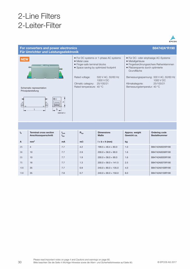
For converters and power electronicsFür Umrichter und Leistungselektronik
VV For DC systems or 1-phase AC systemsVV Metal caseVV Finger-safe terminal blocksVV Space saving by optimized footprint
Rated voltage: 500 V AC, 50/60 Hz 1000 V DCClimatic category: 25/100/21Rated temperature: 40 °C
VV Für DC- oder einphasige AC-SystemeVV MetallgehäuseVV Fingerberührungssichere ReihenklemmenVV Platzersparnis durch optimierte Grundfläche
Bemessungsspannung: 500 V AC, 50/60 Hz 1000 V DCKlimakategorie: 25/100/21Bemessungstemperatur: 40 °CSchematic representation
Prinzipdarstellung
SSB1967-2
b
h
IR Terminal cross sectionAnschlussquerschnitt
Ileak
IAbl
Rtyp DimensionsMaße
Approx. weightGewicht ca.
Ordering codeBestellnummer
A mm2 mA mΩ l × b × h (mm) kg
25 4 7.7 4.2 199.5 × 46.4 × 83.0 1.0 B84742A0025R190
36 10 7.7 2.9 200.0 × 58.0 × 90.0 1.6 B84742A0036R190
55 10 7.7 1.9 200.0 × 58.0 × 90.0 1.6 B84742A0055R190
75 16 7.7 1.3 200.0 × 58.0 × 141.5 2.5 B84742A0075R190
100 35 7.7 0.9 240.0 × 80.0 × 135.0 4.0 B84742A0100R190
130 35 7.8 0.7 240.0 × 90.0 × 150.0 8.0 B84742A0130R190
B84742A*R190
NEWNEW
31© EPCOS AG 2017Please read Important notes on page 4 and Cautions and warnings on page 80.
Bitte beachten Sie die Seite 4 Wichtige Hinweise sowie die Warn- und Sicherheitshinweise auf Seite 80.
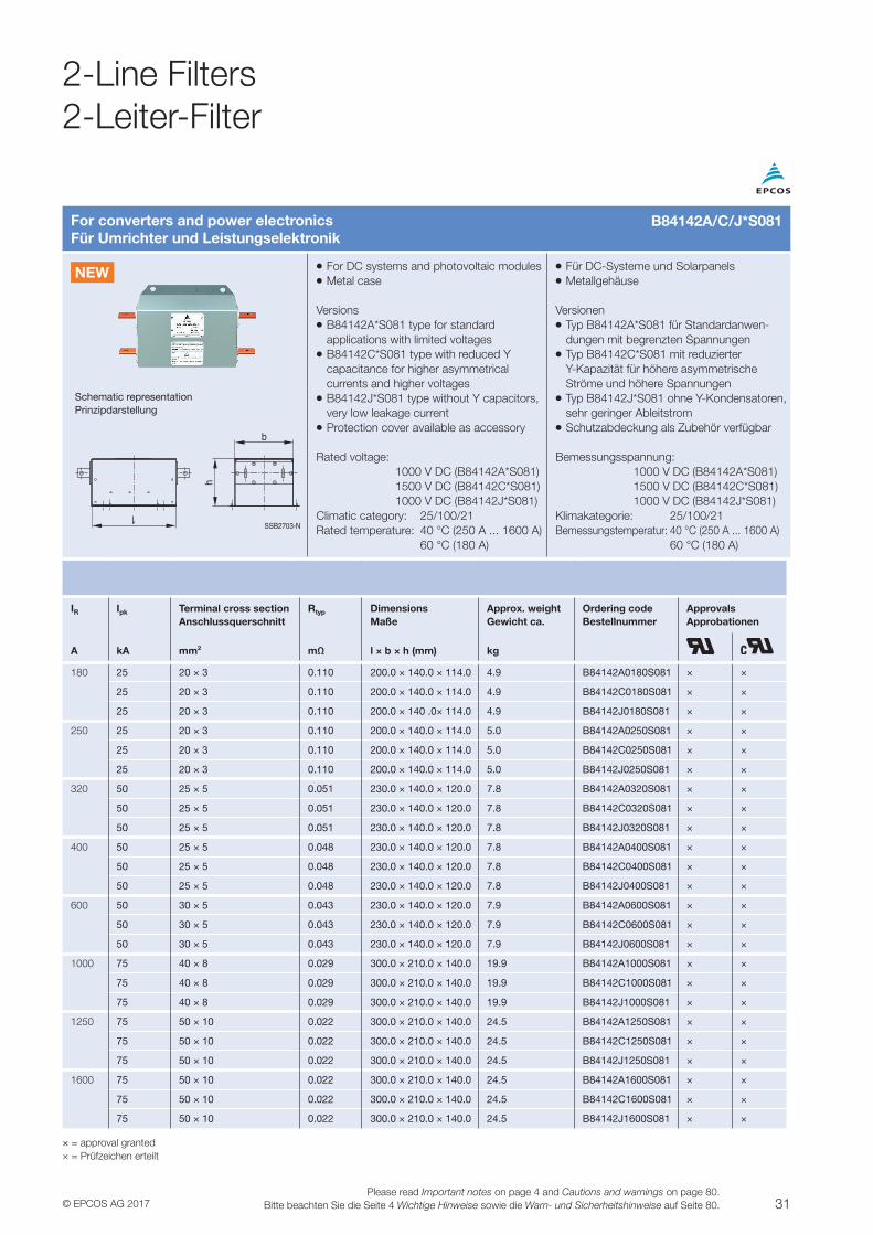
For converters and power electronicsFür Umrichter und Leistungselektronik
VV For DC systems and photovoltaic modulesVV Metal case
VersionsVV B84142A*S081 type for standard applications with limited voltagesVV B84142C*S081 type with reduced Y capacitance for higher asymmetrical currents and higher voltagesVV B84142J*S081 type without Y capacitors, very low leakage currentVV Protection cover available as accessory
Rated voltage: 1000 V DC (B84142A*S081) 1500 V DC (B84142C*S081) 1000 V DC (B84142J*S081)Climatic category: 25/100/21Rated temperature: 40 °C (250 A ... 1600 A) 60 °C (180 A)
VV Für DC-Systeme und SolarpanelsVV Metallgehäuse
VersionenVV Typ B84142A*S081 für Standardanwen-dungen mit begrenzten SpannungenVV Typ B84142C*S081 mit reduzierter Y-Kapazität für höhere asymmetrische Ströme und höhere SpannungenVV Typ B84142J*S081 ohne Y-Kondensatoren, sehr geringer AbleitstromVV Schutzabdeckung als Zubehör verfügbar
Bemessungsspannung: 1000 V DC (B84142A*S081) 1500 V DC (B84142C*S081) 1000 V DC (B84142J*S081)Klimakategorie: 25/100/21Bemessungstemperatur: 40 °C (250 A ... 1600 A) 60 °C (180 A)
Schematic representationPrinzipdarstellung
SSB2703-N
b
h
IR Ipk Terminal cross sectionAnschlussquerschnitt
Rtyp DimensionsMaße
Approx. weightGewicht ca.
Ordering codeBestellnummer
ApprovalsApprobationen
A kA mm2 mΩ l × b × h (mm) kg
180 25 20 × 3 0.110 200.0 × 140.0 × 114.0 4.9 B84142A0180S081 × ×
25 20 × 3 0.110 200.0 × 140.0 × 114.0 4.9 B84142C0180S081 × ×
25 20 × 3 0.110 200.0 × 140 .0× 114.0 4.9 B84142J0180S081 × ×
250 25 20 × 3 0.110 200.0 × 140.0 × 114.0 5.0 B84142A0250S081 × ×
25 20 × 3 0.110 200.0 × 140.0 × 114.0 5.0 B84142C0250S081 × ×
25 20 × 3 0.110 200.0 × 140.0 × 114.0 5.0 B84142J0250S081 × ×
320 50 25 × 5 0.051 230.0 × 140.0 × 120.0 7.8 B84142A0320S081 × ×
50 25 × 5 0.051 230.0 × 140.0 × 120.0 7.8 B84142C0320S081 × ×
50 25 × 5 0.051 230.0 × 140.0 × 120.0 7.8 B84142J0320S081 × ×
400 50 25 × 5 0.048 230.0 × 140.0 × 120.0 7.8 B84142A0400S081 × ×
50 25 × 5 0.048 230.0 × 140.0 × 120.0 7.8 B84142C0400S081 × ×
50 25 × 5 0.048 230.0 × 140.0 × 120.0 7.8 B84142J0400S081 × ×
600 50 30 × 5 0.043 230.0 × 140.0 × 120.0 7.9 B84142A0600S081 × ×
50 30 × 5 0.043 230.0 × 140.0 × 120.0 7.9 B84142C0600S081 × ×
50 30 × 5 0.043 230.0 × 140.0 × 120.0 7.9 B84142J0600S081 × ×
1000 75 40 × 8 0.029 300.0 × 210.0 × 140.0 19.9 B84142A1000S081 × ×
75 40 × 8 0.029 300.0 × 210.0 × 140.0 19.9 B84142C1000S081 × ×
75 40 × 8 0.029 300.0 × 210.0 × 140.0 19.9 B84142J1000S081 × ×
1250 75 50 × 10 0.022 300.0 × 210.0 × 140.0 24.5 B84142A1250S081 × ×
75 50 × 10 0.022 300.0 × 210.0 × 140.0 24.5 B84142C1250S081 × ×
75 50 × 10 0.022 300.0 × 210.0 × 140.0 24.5 B84142J1250S081 × ×
1600 75 50 × 10 0.022 300.0 × 210.0 × 140.0 24.5 B84142A1600S081 × ×
75 50 × 10 0.022 300.0 × 210.0 × 140.0 24.5 B84142C1600S081 × ×
75 50 × 10 0.022 300.0 × 210.0 × 140.0 24.5 B84142J1600S081 × ×
× = approval granted× = Prüfzeichen erteilt
B84142A/C/J*S081
2-Line Filters2-Leiter-Filter
NEW
32 © EPCOS AG 2017Please read Important notes on page 4 and Cautions and warnings on page 80.Bitte beachten Sie die Seite 4 Wichtige Hinweise sowie die Warn- und Sicherheitshinweise auf Seite 80.
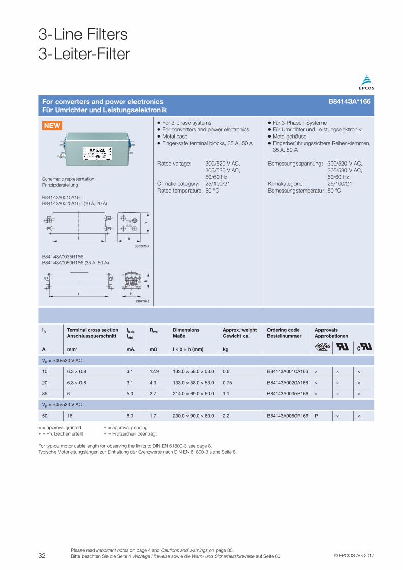
For converters and power electronicsFür Umrichter und Leistungselektronik
VV For 3-phase systemsVV For converters and power electronicsVV Metal caseVV Finger-safe terminal blocks, 35 A, 50 A
Rated voltage: 300/520 V AC, 305/530 V AC, 50/60 HzClimatic category: 25/100/21Rated temperature: 50 °C
VV Für 3-Phasen-SystemeVV Für Umrichter und LeistungselektronikVV MetallgehäuseVV Fingerberührungssichere Reihenklemmen, 35 A, 50 A
Bemessungsspannung: 300/520 V AC, 305/530 V AC, 50/60 HzKlimakategorie: 25/100/21Bemessungstemperatur: 50 °C
Schematic representationPrinzipdarstellung
B84143A0010A166, B84143A0020A166 (10 A, 20 A)
b
h
SSB2725-J
L1
L2 L3
PE
B84143A0035R166, B84143A0050R166 (35 A, 50 A)
b
h
SSB2726-S
IR Terminal cross section Anschlussquerschnitt
Ileak
IAbl
Rtyp DimensionsMaße
Approx. weightGewicht ca.
Ordering codeBestellnummer
ApprovalsApprobationen
A mm2 mA mΩ l × b × h (mm) kg
VR = 300/520 V AC
10 6.3 × 0.8 3.1 12.9 133.0 × 58.0 × 53.0 0.6 B84143A0010A166 × × ×
20 6.3 × 0.8 3.1 4.9 133.0 × 58.0 × 53.0 0.75 B84143A0020A166 × × ×
35 6 5.0 2.7 214.0 × 69.0 × 60.0 1.1 B84143A0035R166 × × ×
VR = 305/530 V AC
50 16 8.0 1.7 230.0 × 90.0 × 60.0 2.2 B84143A0050R166 P × ×
× = approval granted P = approval pending× = Prüfzeichen erteilt P = Prüfzeichen beantragt
For typical motor cable length for observing the limits to DIN EN 61800-3 see page 8.Typische Motorleitungslängen zur Einhaltung der Grenzwerte nach DIN EN 61800-3 siehe Seite 8.
B84143A*166
NEW
3-Line Filters3-Leiter-Filter
33© EPCOS AG 2017Please read Important notes on page 4 and Cautions and warnings on page 80.
Bitte beachten Sie die Seite 4 Wichtige Hinweise sowie die Warn- und Sicherheitshinweise auf Seite 80.
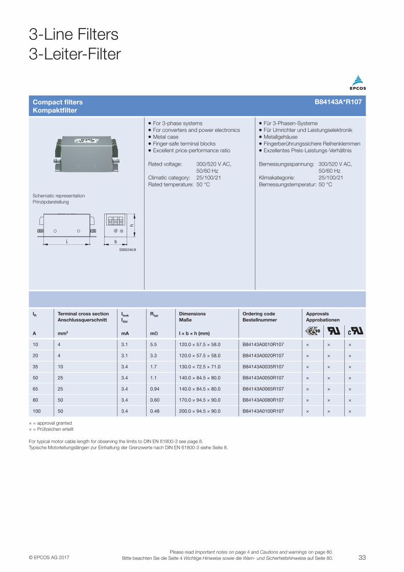
Compact filtersKompaktfilter
VV For 3-phase systemsVV For converters and power electronicsVV Metal caseVV Finger-safe terminal blocksVV Excellent price-performance ratio
Rated voltage: 300/520 V AC, 50/60 HzClimatic category: 25/100/21Rated temperature: 50 °C
VV Für 3-Phasen-SystemeVV Für Umrichter und LeistungselektronikVV MetallgehäuseVV Fingerberührungssichere ReihenklemmenVV Exzellentes Preis-Leistungs-Verhältnis
Bemessungsspannung: 300/520 V AC, 50/60 HzKlimakategorie: 25/100/21Bemessungstemperatur: 50 °C
Schematic representationPrinzipdarstellung
SSB2246-B
b
h
IR Terminal cross section Anschlussquerschnitt
Ileak
IAbl
Rtyp DimensionsMaße
Ordering codeBestellnummer
ApprovalsApprobationen
A mm2 mA mΩ l × b × h (mm)
10 4 3.1 5.5 120.0 × 57.5 × 58.0 B84143A0010R107 × × ×
20 4 3.1 3.3 120.0 × 57.5 × 58.0 B84143A0020R107 × × ×
35 10 3.4 1.7 130.0 × 72.5 × 71.0 B84143A0035R107 × × ×
50 25 3.4 1.1 140.0 × 84.5 × 80.0 B84143A0050R107 × × ×
65 25 3.4 0.94 140.0 × 84.5 × 80.0 B84143A0065R107 × × ×
80 50 3.4 0.60 170.0 × 94.5 × 90.0 B84143A0080R107 × × ×
100 50 3.4 0.48 200.0 × 94.5 × 90.0 B84143A0100R107 × × ×
× = approval granted× = Prüfzeichen erteilt
For typical motor cable length for observing the limits to DIN EN 61800-3 see page 8.Typische Motorleitungslängen zur Einhaltung der Grenzwerte nach DIN EN 61800-3 siehe Seite 8.
B84143A*R107
3-Line Filters3-Leiter-Filter
34 © EPCOS AG 2017Please read Important notes on page 4 and Cautions and warnings on page 80.Bitte beachten Sie die Seite 4 Wichtige Hinweise sowie die Warn- und Sicherheitshinweise auf Seite 80.
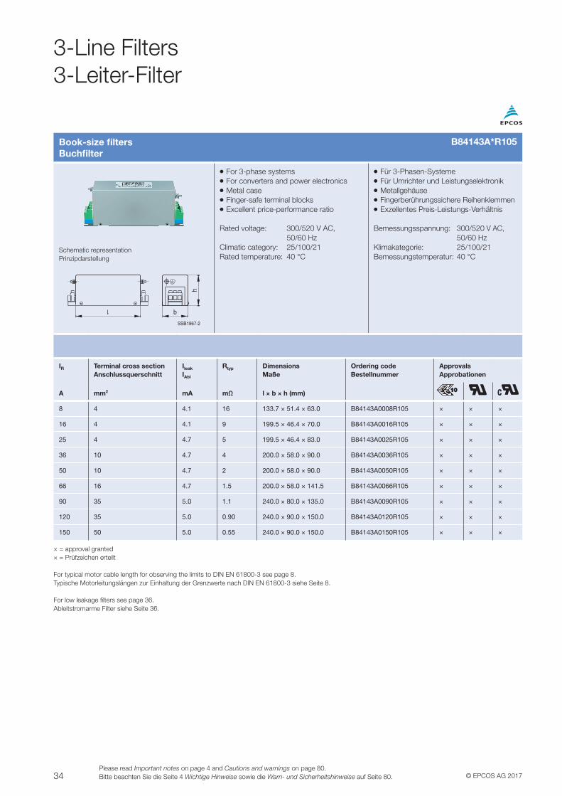
Book-size filtersBuchfilter
VV For 3-phase systemsVV For converters and power electronicsVV Metal caseVV Finger-safe terminal blocksVV Excellent price-performance ratio
Rated voltage: 300/520 V AC, 50/60 HzClimatic category: 25/100/21Rated temperature: 40 °C
VV Für 3-Phasen-SystemeVV Für Umrichter und LeistungselektronikVV MetallgehäuseVV Fingerberührungssichere ReihenklemmenVV Exzellentes Preis-Leistungs-Verhältnis
Bemessungsspannung: 300/520 V AC, 50/60 HzKlimakategorie: 25/100/21Bemessungstemperatur: 40 °C
Schematic representationPrinzipdarstellung
SSB1967-2
b
h
IR Terminal cross section Anschlussquerschnitt
Ileak
IAbl
Rtyp DimensionsMaße
Ordering codeBestellnummer
ApprovalsApprobationen
A mm2 mA mΩ l × b × h (mm)
8 4 4.1 16 133.7 × 51.4 × 63.0 B84143A0008R105 × × ×
16 4 4.1 9 199.5 × 46.4 × 70.0 B84143A0016R105 × × ×
25 4 4.7 5 199.5 × 46.4 × 83.0 B84143A0025R105 × × ×
36 10 4.7 4 200.0 × 58.0 × 90.0 B84143A0036R105 × × ×
50 10 4.7 2 200.0 × 58.0 × 90.0 B84143A0050R105 × × ×
66 16 4.7 1.5 200.0 × 58.0 × 141.5 B84143A0066R105 × × ×
90 35 5.0 1.1 240.0 × 80.0 × 135.0 B84143A0090R105 × × ×
120 35 5.0 0.90 240.0 × 90.0 × 150.0 B84143A0120R105 × × ×
150 50 5.0 0.55 240.0 × 90.0 × 150.0 B84143A0150R105 × × ×
× = approval granted× = Prüfzeichen erteilt
For typical motor cable length for observing the limits to DIN EN 61800-3 see page 8.Typische Motorleitungslängen zur Einhaltung der Grenzwerte nach DIN EN 61800-3 siehe Seite 8.
For low leakage filters see page 36.Ableitstromarme Filter siehe Seite 36.
B84143A*R105
3-Line Filters3-Leiter-Filter
35© EPCOS AG 2017Please read Important notes on page 4 and Cautions and warnings on page 80.
Bitte beachten Sie die Seite 4 Wichtige Hinweise sowie die Warn- und Sicherheitshinweise auf Seite 80.
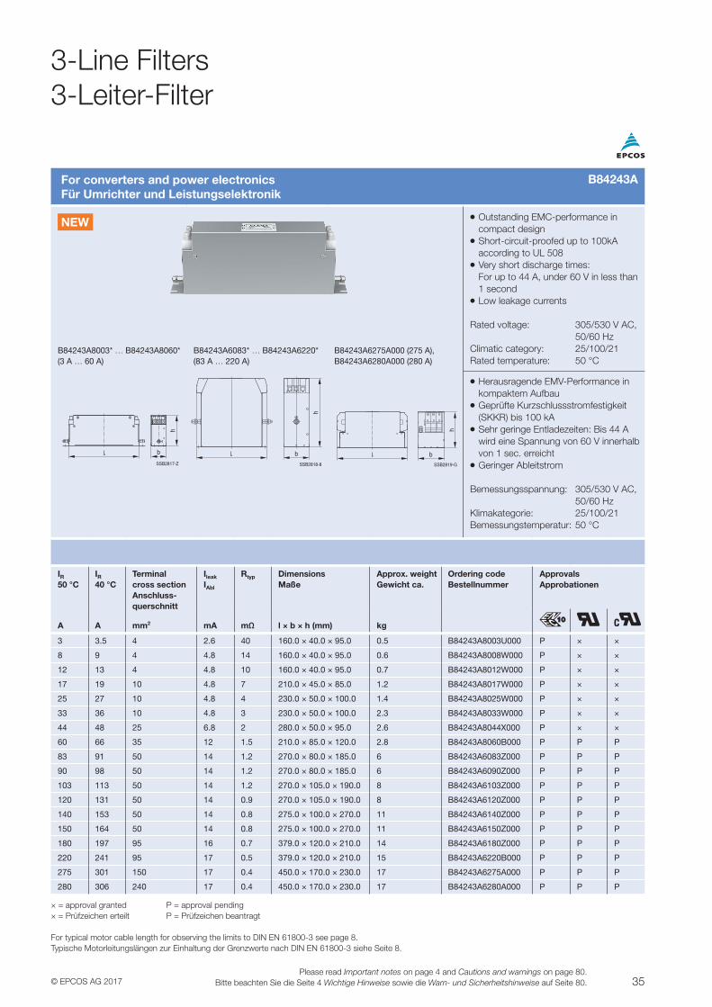
For converters and power electronicsFür Umrichter und Leistungselektronik
VV Outstanding EMC-performance in compact designVV Short-circuit-proofed up to 100kA according to UL 508VV Very short discharge times: For up to 44 A, under 60 V in less than 1 secondVV Low leakage currents
Rated voltage: 305/530 V AC, 50/60 HzClimatic category: 25/100/21Rated temperature: 50 °C
B84243A8003* … B84243A8060* (3 A … 60 A)
B84243A6083* … B84243A6220* (83 A … 220 A)
B84243A6275A000 (275 A), B84243A6280A000 (280 A)
SSB2817-Z
b
h
SSB2818-8
h
b
SSB2819-G
hb
VV Herausragende EMV-Performance in kompaktem AufbauVV Geprüfte Kurzschlussstromfestigkeit (SKKR) bis 100 kAVV Sehr geringe Entladezeiten: Bis 44 A wird eine Spannung von 60 V innerhalb von 1 sec. erreicht VV Geringer Ableitstrom
Bemessungsspannung: 305/530 V AC, 50/60 HzKlimakategorie: 25/100/21Bemessungstemperatur: 50 °C
IR50 °C
IR40 °C
Terminal cross section Anschluss- querschnitt
Ileak
IAbl
Rtyp DimensionsMaße
Approx. weightGewicht ca.
Ordering codeBestellnummer
ApprovalsApprobationen
A A mm2 mA mΩ l × b × h (mm) kg
3 3.5 4 2.6 40 160.0 × 40.0 × 95.0 0.5 B84243A8003U000 P × ×
8 9 4 4.8 14 160.0 × 40.0 × 95.0 0.6 B84243A8008W000 P × ×
12 13 4 4.8 10 160.0 × 40.0 × 95.0 0.7 B84243A8012W000 P × ×
17 19 10 4.8 7 210.0 × 45.0 × 85.0 1.2 B84243A8017W000 P × ×
25 27 10 4.8 4 230.0 × 50.0 × 100.0 1.4 B84243A8025W000 P × ×
33 36 10 4.8 3 230.0 × 50.0 × 100.0 2.3 B84243A8033W000 P × ×
44 48 25 6.8 2 280.0 × 50.0 × 95.0 2.6 B84243A8044X000 P × ×
60 66 35 12 1.5 210.0 × 85.0 × 120.0 2.8 B84243A8060B000 P P P
83 91 50 14 1.2 270.0 × 80.0 × 185.0 6 B84243A6083Z000 P P P
90 98 50 14 1.2 270.0 × 80.0 × 185.0 6 B84243A6090Z000 P P P
103 113 50 14 1.2 270.0 × 105.0 × 190.0 8 B84243A6103Z000 P P P
120 131 50 14 0.9 270.0 × 105.0 × 190.0 8 B84243A6120Z000 P P P
140 153 50 14 0.8 275.0 × 100.0 × 270.0 11 B84243A6140Z000 P P P
150 164 50 14 0.8 275.0 × 100.0 × 270.0 11 B84243A6150Z000 P P P
180 197 95 16 0.7 379.0 × 120.0 × 210.0 14 B84243A6180Z000 P P P
220 241 95 17 0.5 379.0 × 120.0 × 210.0 15 B84243A6220B000 P P P
275 301 150 17 0.4 450.0 × 170.0 × 230.0 17 B84243A6275A000 P P P
280 306 240 17 0.4 450.0 × 170.0 × 230.0 17 B84243A6280A000 P P P
× = approval granted P = approval pending× = Prüfzeichen erteilt P = Prüfzeichen beantragt
For typical motor cable length for observing the limits to DIN EN 61800-3 see page 8.Typische Motorleitungslängen zur Einhaltung der Grenzwerte nach DIN EN 61800-3 siehe Seite 8.
B84243A
NEW
3-Line Filters3-Leiter-Filter
36 © EPCOS AG 2017Please read Important notes on page 4 and Cautions and warnings on page 80.Bitte beachten Sie die Seite 4 Wichtige Hinweise sowie die Warn- und Sicherheitshinweise auf Seite 80.
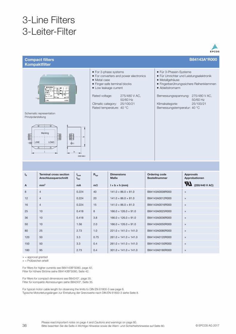
Compact filtersKompaktfilter
VV For 3-phase systemsVV For converters and power electronicsVV Metal caseVV Finger-safe terminal blocksVV Low leakage current
Rated voltage: 275/480 V AC, 50/60 HzClimatic category: 25/100/21Rated temperature: 40 °C
VV Für 3-Phasen-SystemeVV Für Umrichter und LeistungselektronikVV MetallgehäuseVV Fingerberührungssichere ReihenklemmenVV Ableitstromarm
Bemessungsspannung: 275/480 V AC, 50/60 HzKlimakategorie: 25/100/21Bemessungstemperatur: 40 °C
Schematic representationPrinzipdarstellung
SSB1888-I
LINE LOAD
h
Marking
b
IR Terminal cross section Anschlussquerschnitt
Ileak
IAbl
Rtyp DimensionsMaße
Ordering codeBestellnummer
ApprovalsApprobationen
A mm2 mA mΩ l × b × h (mm) (250/440 V AC)
8 4 0.224 40 141.0 × 86.0 × 81.0 B84143A0008R000 ×
12 4 0.224 20 141.0 × 86.0 × 81.0 B84143A0012R000 ×
16 4 0.224 15 141.0 × 86.0 × 81.0 B84143A0016R000 ×
25 10 0.418 8 166.0 × 126.0 × 91.0 B84143A0025R000 ×
36 10 0.418 3.8 166.0 × 126.0 × 91.0 B84143A0036R000 ×
50 10 1.56 2.0 166.0 × 126.0 × 91.0 B84143A0050R000 ×
80 25 2.73 1.0 221.0 × 141.0 × 141.0 B84143A0080R000 ×
120 50 3.3 0.75 261.0 × 141.0 × 141.0 B84143A0120R000 ×
150 50 3.3 0.4 261.0 × 141.0 × 141.0 B84143A0150R000 ×
180 95 2.73 0.4 301.0 × 141.0 × 141.0 B84143A0180R000 ×
× = approval granted× = Prüfzeichen erteilt
For filters for higher currents see B84143B*S080, page 42.Filter für höhere Ströme siehe B84143B*S080, Seite 42.
For filters for compact dimensions see B84243*, page 35.Filter für kompakte Abmessungen siehe B84243*, Seite 35.
For typical motor cable length for observing the limits to DIN EN 61800-3 see page 8.Typische Motorleitungslängen zur Einhaltung der Grenzwerte nach DIN EN 61800-3 siehe Seite 8.
B84143A*R000
3-Line Filters3-Leiter-Filter
37© EPCOS AG 2017Please read Important notes on page 4 and Cautions and warnings on page 80.
Bitte beachten Sie die Seite 4 Wichtige Hinweise sowie die Warn- und Sicherheitshinweise auf Seite 80.
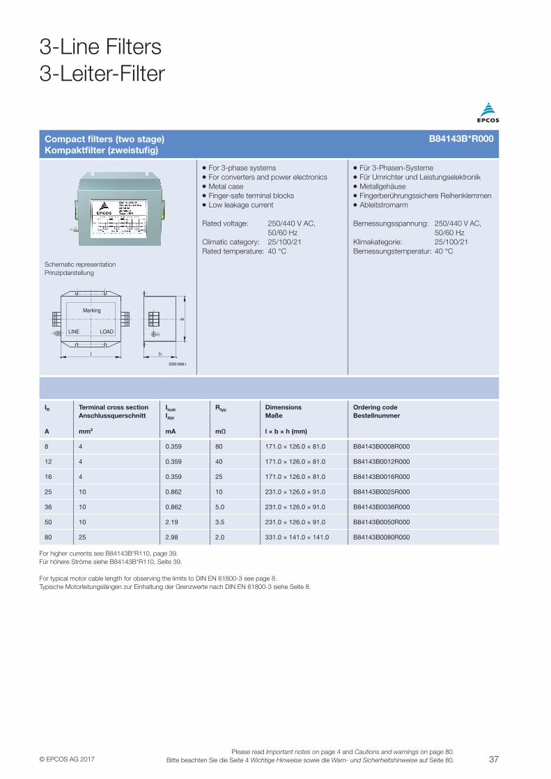
Compact filters (two stage)Kompaktfilter (zweistufig)
VV For 3-phase systemsVV For converters and power electronicsVV Metal caseVV Finger-safe terminal blocksVV Low leakage current
Rated voltage: 250/440 V AC, 50/60 HzClimatic category: 25/100/21Rated temperature: 40 °C
VV Für 3-Phasen-SystemeVV Für Umrichter und LeistungselektronikVV MetallgehäuseVV Fingerberührungssichere ReihenklemmenVV Ableitstromarm
Bemessungsspannung: 250/440 V AC, 50/60 HzKlimakategorie: 25/100/21Bemessungstemperatur: 40 °C
Schematic representationPrinzipdarstellung
SSB1888-I
LINE LOAD
h
Marking
b
IR Terminal cross section Anschlussquerschnitt
Ileak
IAbl
Rtyp DimensionsMaße
Ordering codeBestellnummer
A mm2 mA mΩ l × b × h (mm)
8 4 0.359 80 171.0 × 126.0 × 81.0 B84143B0008R000
12 4 0.359 40 171.0 × 126.0 × 81.0 B84143B0012R000
16 4 0.359 25 171.0 × 126.0 × 81.0 B84143B0016R000
25 10 0.862 10 231.0 × 126.0 × 91.0 B84143B0025R000
36 10 0.862 5.0 231.0 × 126.0 × 91.0 B84143B0036R000
50 10 2.19 3.5 231.0 × 126.0 × 91.0 B84143B0050R000
80 25 2.98 2.0 331.0 × 141.0 × 141.0 B84143B0080R000
For higher currents see B84143B*R110, page 39.Für höhere Ströme siehe B84143B*R110, Seite 39.
For typical motor cable length for observing the limits to DIN EN 61800-3 see page 8.Typische Motorleitungslängen zur Einhaltung der Grenzwerte nach DIN EN 61800-3 siehe Seite 8.
B84143B*R000
3-Line Filters3-Leiter-Filter
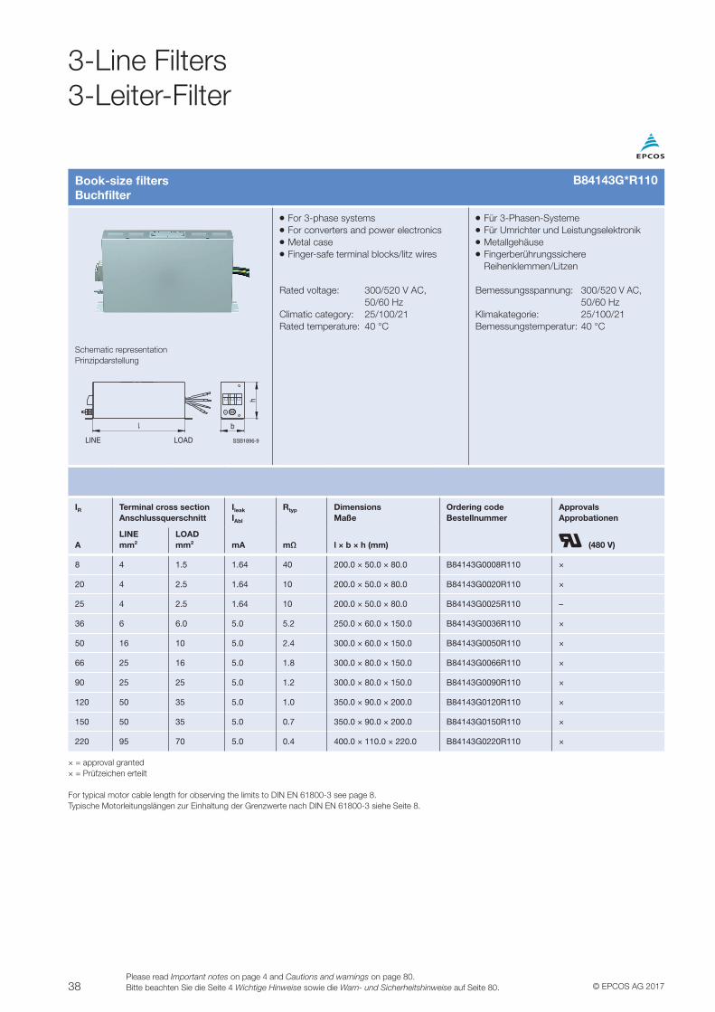
38 © EPCOS AG 2017Please read Important notes on page 4 and Cautions and warnings on page 80.Bitte beachten Sie die Seite 4 Wichtige Hinweise sowie die Warn- und Sicherheitshinweise auf Seite 80.
Book-size filtersBuchfilter
VV For 3-phase systemsVV For converters and power electronicsVV Metal caseVV Finger-safe terminal blocks/litz wires
Rated voltage: 300/520 V AC, 50/60 HzClimatic category: 25/100/21Rated temperature: 40 °C
VV Für 3-Phasen-SystemeVV Für Umrichter und LeistungselektronikVV MetallgehäuseVV Fingerberührungssichere Reihenklemmen/Litzen
Bemessungsspannung: 300/520 V AC, 50/60 HzKlimakategorie: 25/100/21Bemessungstemperatur: 40 °C
Schematic representationPrinzipdarstellung
SSB1896-9
b
h
LINE LOAD
IR Terminal cross sectionAnschlussquerschnitt
Ileak
IAbl
Rtyp DimensionsMaße
Ordering codeBestellnummer
ApprovalsApprobationen
ALINEmm2
LOADmm2 mA mΩ l × b × h (mm) (480 V)
8 4 1.5 1.64 40 200.0 × 50.0 × 80.0 B84143G0008R110 ×
20 4 2.5 1.64 10 200.0 × 50.0 × 80.0 B84143G0020R110 ×
25 4 2.5 1.64 10 200.0 × 50.0 × 80.0 B84143G0025R110 –
36 6 6.0 5.0 5.2 250.0 × 60.0 × 150.0 B84143G0036R110 ×
50 16 10 5.0 2.4 300.0 × 60.0 × 150.0 B84143G0050R110 ×
66 25 16 5.0 1.8 300.0 × 80.0 × 150.0 B84143G0066R110 ×
90 25 25 5.0 1.2 300.0 × 80.0 × 150.0 B84143G0090R110 ×
120 50 35 5.0 1.0 350.0 × 90.0 × 200.0 B84143G0120R110 ×
150 50 35 5.0 0.7 350.0 × 90.0 × 200.0 B84143G0150R110 ×
220 95 70 5.0 0.4 400.0 × 110.0 × 220.0 B84143G0220R110 ×
× = approval granted× = Prüfzeichen erteilt
For typical motor cable length for observing the limits to DIN EN 61800-3 see page 8.Typische Motorleitungslängen zur Einhaltung der Grenzwerte nach DIN EN 61800-3 siehe Seite 8.
B84143G*R110
3-Line Filters3-Leiter-Filter
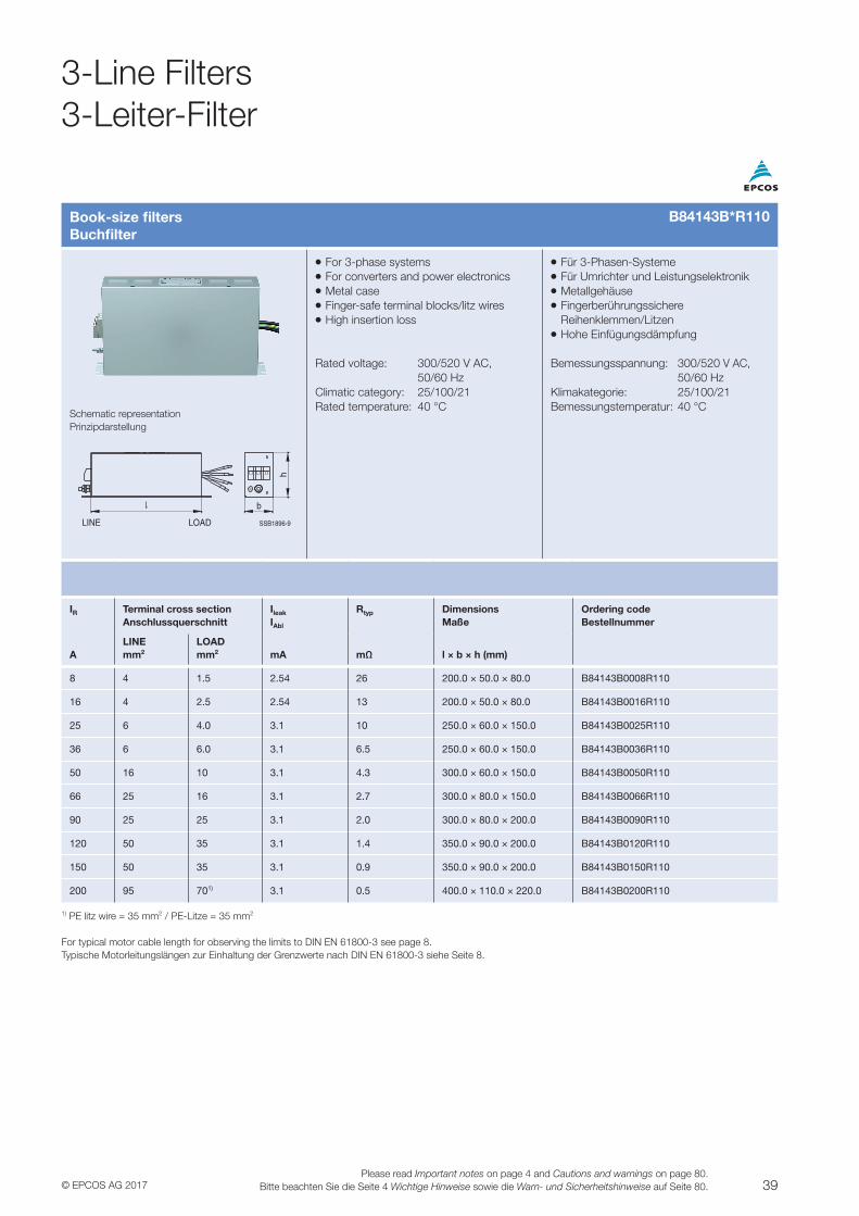
39© EPCOS AG 2017Please read Important notes on page 4 and Cautions and warnings on page 80.
Bitte beachten Sie die Seite 4 Wichtige Hinweise sowie die Warn- und Sicherheitshinweise auf Seite 80.
Book-size filtersBuchfilter
VV For 3-phase systemsVV For converters and power electronicsVV Metal caseVV Finger-safe terminal blocks/litz wiresVV High insertion loss
Rated voltage: 300/520 V AC, 50/60 HzClimatic category: 25/100/21Rated temperature: 40 °C
VV Für 3-Phasen-SystemeVV Für Umrichter und LeistungselektronikVV MetallgehäuseVV Fingerberührungssichere Reihenklemmen/LitzenVV Hohe Einfügungsdämpfung
Bemessungsspannung: 300/520 V AC, 50/60 HzKlimakategorie: 25/100/21Bemessungstemperatur: 40 °C
Schematic representationPrinzipdarstellung
SSB1896-9
b
h
LINE LOAD
IR Terminal cross sectionAnschlussquerschnitt
Ileak
IAbl
Rtyp DimensionsMaße
Ordering codeBestellnummer
ALINEmm2
LOADmm2 mA mΩ l × b × h (mm)
8 4 1.5 2.54 26 200.0 × 50.0 × 80.0 B84143B0008R110
16 4 2.5 2.54 13 200.0 × 50.0 × 80.0 B84143B0016R110
25 6 4.0 3.1 10 250.0 × 60.0 × 150.0 B84143B0025R110
36 6 6.0 3.1 6.5 250.0 × 60.0 × 150.0 B84143B0036R110
50 16 10 3.1 4.3 300.0 × 60.0 × 150.0 B84143B0050R110
66 25 16 3.1 2.7 300.0 × 80.0 × 150.0 B84143B0066R110
90 25 25 3.1 2.0 300.0 × 80.0 × 200.0 B84143B0090R110
120 50 35 3.1 1.4 350.0 × 90.0 × 200.0 B84143B0120R110
150 50 35 3.1 0.9 350.0 × 90.0 × 200.0 B84143B0150R110
200 95 701) 3.1 0.5 400.0 × 110.0 × 220.0 B84143B0200R110
1) PE litz wire = 35 mm2 / PE-Litze = 35 mm2
For typical motor cable length for observing the limits to DIN EN 61800-3 see page 8.Typische Motorleitungslängen zur Einhaltung der Grenzwerte nach DIN EN 61800-3 siehe Seite 8.
B84143B*R110
3-Line Filters3-Leiter-Filter
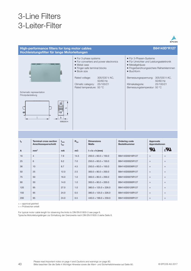
40 © EPCOS AG 2017Please read Important notes on page 4 and Cautions and warnings on page 80.Bitte beachten Sie die Seite 4 Wichtige Hinweise sowie die Warn- und Sicherheitshinweise auf Seite 80.
High-performance filters for long motor cablesHochleistungsfilter für lange Motorleitungen
VV For 3-phase systemsVV For converters and power electronicsVV Metal caseVV Finger-safe terminal blocksVV Book size
Rated voltage: 305/530 V AC, 50/60 HzClimatic category: 25/100/21Rated temperature: 50 °C
VV Für 3-Phasen-SystemeVV Für Umrichter und LeistungselektronikVV MetallgehäuseVV Fingerberührungssichere ReihenklemmenVV Buchform
Bemessungsspannung: 305/530 V AC, 50/60 HzKlimakategorie: 25/100/21Bemessungstemperatur: 50 °C
Schematic representationPrinzipdarstellung
SSB2255-A
h
b
IR Terminal cross section Anschlussquerschnitt
Ileak
IAbl
Rtyp DimensionsMaße
Ordering codeBestellnummer
ApprovalsApprobationen
A mm2 mA mΩ l × b × h (mm)
16 4 7.9 14.5 250.0 × 60.0 × 150.0 B84143D0016R127 × ×
25 6 9.2 7.0 250.0 × 60.0 × 150.0 B84143D0025R127 × ×
36 10 8.7 4.5 250.0 × 60.0 × 150.0 B84143D0036R127 × ×
50 25 12.0 2.5 300.0 × 80.0 × 200.0 B84143D0050R127 × ×
75 50 16.0 1.0 300.0 × 80.0 × 200.0 B84143D0075R127 × ×
90 50 14.0 1.0 300.0 × 80.0 × 200.0 B84143D0090R127 × ×
120 95 27.0 1.0 380.0 × 125.0 × 226.0 B84143D0120R127 × ×
150 95 24.0 0.5 380.0 × 125.0 × 226.0 B84143D0150R127 × ×
200 95 24.0 0.5 440.0 × 199.0 × 259.0 B84143D0200R127 × ×
× = approval granted× = Prüfzeichen erteilt
For typical motor cable length for observing the limits to DIN EN 61800-3 see page 8.Typische Motorleitungslängen zur Einhaltung der Grenzwerte nach DIN EN 61800-3 siehe Seite 8.
3-Line Filters3-Leiter-Filter
B84143D*R127
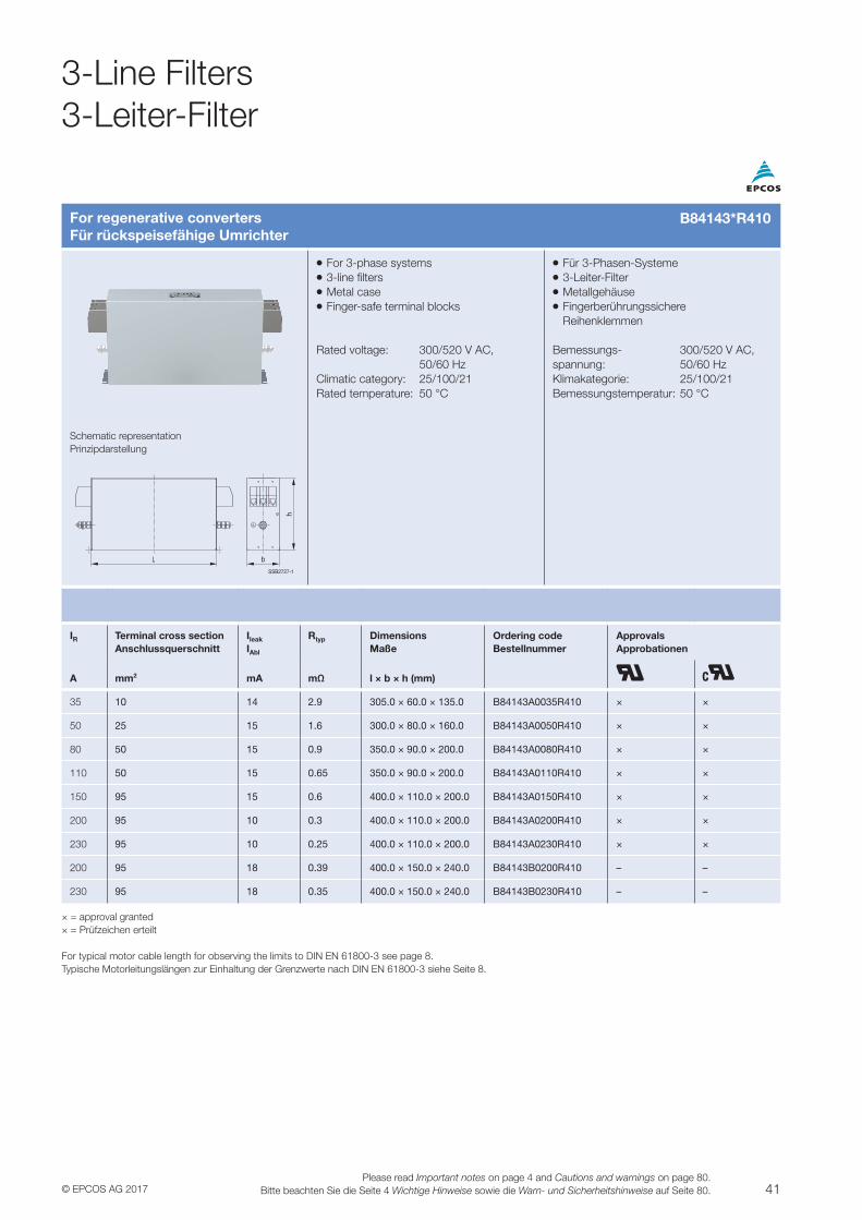
41© EPCOS AG 2017Please read Important notes on page 4 and Cautions and warnings on page 80.
Bitte beachten Sie die Seite 4 Wichtige Hinweise sowie die Warn- und Sicherheitshinweise auf Seite 80.
For regenerative convertersFür rückspeisefähige Umrichter
Schematic representationPrinzipdarstellung
b
h
SSB2727-1
VV For 3-phase systemsVV 3-line filtersVV Metal caseVV Finger-safe terminal blocks
Rated voltage: 300/520 V AC, 50/60 HzClimatic category: 25/100/21Rated temperature: 50 °C
VV Für 3-Phasen-SystemeVV 3-Leiter-FilterVV MetallgehäuseVV Fingerberührungssichere Reihenklemmen
Bemessungs- 300/520 V AC,spannung: 50/60 HzKlimakategorie: 25/100/21Bemessungstemperatur: 50 °C
IR Terminal cross section Anschlussquerschnitt
Ileak
IAbl
Rtyp DimensionsMaße
Ordering codeBestellnummer
ApprovalsApprobationen
A mm2 mA mΩ l × b × h (mm)
35 10 14 2.9 305.0 × 60.0 × 135.0 B84143A0035R410 × ×
50 25 15 1.6 300.0 × 80.0 × 160.0 B84143A0050R410 × ×
80 50 15 0.9 350.0 × 90.0 × 200.0 B84143A0080R410 × ×
110 50 15 0.65 350.0 × 90.0 × 200.0 B84143A0110R410 × ×
150 95 15 0.6 400.0 × 110.0 × 200.0 B84143A0150R410 × ×
200 95 10 0.3 400.0 × 110.0 × 200.0 B84143A0200R410 × ×
230 95 10 0.25 400.0 × 110.0 × 200.0 B84143A0230R410 × ×
200 95 18 0.39 400.0 × 150.0 × 240.0 B84143B0200R410 – –
230 95 18 0.35 400.0 × 150.0 × 240.0 B84143B0230R410 – –
× = approval granted× = Prüfzeichen erteilt
For typical motor cable length for observing the limits to DIN EN 61800-3 see page 8.Typische Motorleitungslängen zur Einhaltung der Grenzwerte nach DIN EN 61800-3 siehe Seite 8.
B84143*R410
3-Line Filters3-Leiter-Filter
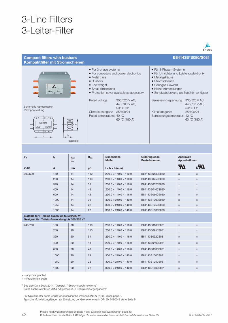
42 © EPCOS AG 2017Please read Important notes on page 4 and Cautions and warnings on page 80.Bitte beachten Sie die Seite 4 Wichtige Hinweise sowie die Warn- und Sicherheitshinweise auf Seite 80.
3-Line Filters3-Leiter-Filter
Compact filters with busbarsKompaktfilter mit Stromschienen
VV For 3-phase systemsVV For converters and power electronicsVV Metal caseVV BusbarsVV Low weightVV Small dimensionsVV Protection cover available as accessory
Rated voltage: 300/520 V AC, 440/760 V AC, 50/60 HzClimatic category: 25/100/21Rated temperature: 40 °C 60 °C (180 A)
VV Für 3-Phasen-SystemeVV Für Umrichter und LeistungselektronikVV MetallgehäuseVV StromschienenVV Geringes GewichtVV Kleine AbmessungenVV Schutzabdeckung als Zubehör verfügbar
Bemessungsspannung: 300/520 V AC, 440/760 V AC, 50/60 HzKlimakategorie: 25/100/21Bemessungstemperatur: 40 °C 60 °C (180 A)
Schematic representationPrinzipdarstellung
SSB2082-U
Marking
LINE LOAD
h
b
VR IR Ileak
IAbl
Rtyp DimensionsMaße
Ordering codeBestellnummer
ApprovalsApprobationen
V AC A mA µΩ l × b × h (mm)
300/520 180 14 110 200.0 × 140.0 × 110.0 B84143B0180S080 × ×
250 14 110 200.0 × 140.0 × 110.0 B84143B0250S080 × ×
320 14 51 230.0 × 140.0 × 116.0 B84143B0320S080 × ×
400 14 48 230.0 × 140.0 × 116.0 B84143B0400S080 × ×
600 14 43 230.0 × 140.0 × 116.0 B84143B0600S080 × ×
1000 14 29 300.0 × 210.0 × 140.0 B84143B1000S080 × ×
1250 14 22 300.0 × 210.0 × 140.0 B84143B1250S080 × ×
1600 14 22 300.0 × 210.0 × 140.0 B84143B1600S080 × ×
Suitable for IT mains supply up to 560/320 V1)
Geeignet für IT-Netz-Anwendung bis 560/320 V1)
440/760 180 20 110 200.0 × 140.0 × 110.0 B84143B0180S081 × ×
250 20 110 200.0 × 140.0 × 110.0 B84143B0250S081 × ×
320 20 51 230.0 × 140.0 × 116.0 B84143B0320S081 × ×
400 20 48 230.0 × 140.0 × 116.0 B84143B0400S081 × ×
600 20 43 230.0 × 140.0 × 116.0 B84143B0600S081 × ×
1000 20 29 300.0 × 210.0 × 140.0 B84143B1000S081 × ×
1250 20 22 300.0 × 210.0 × 140.0 B84143B1250S081 × ×
1600 20 22 300.0 × 210.0 × 140.0 B84143B1600S081 × ×
× = approval granted× = Prüfzeichen erteilt
1) See also Data Book 2014, “General, 7 Energy supply networks” Siehe auch Datenbuch 2014, “Allgemeines, 7 Energieversorgungsnetze”
For typical motor cable length for observing the limits to DIN EN 61800-3 see page 8. Typische Motorleitungslängen zur Einhaltung der Grenzwerte nach DIN EN 61800-3 siehe Seite 8.
B84143B*S080/S081
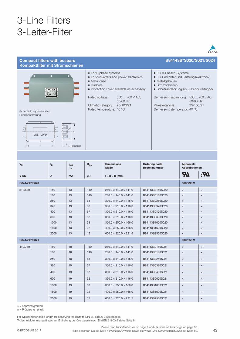
43© EPCOS AG 2017Please read Important notes on page 4 and Cautions and warnings on page 80.
Bitte beachten Sie die Seite 4 Wichtige Hinweise sowie die Warn- und Sicherheitshinweise auf Seite 80.
Compact filters with busbarsKompaktfilter mit Stromschienen
VV For 3-phase systemsVV For converters and power electronicsVV Metal caseVV BusbarsVV Protection cover available as accessory
Rated voltage: 530 ... 760 V AC, 50/60 HzClimatic category: 25/100/21Rated temperature: 40 °C
VV Für 3-Phasen-SystemeVV Für Umrichter und LeistungselektronikVV MetallgehäuseVV StromschienenVV Schutzabdeckung als Zubehör verfügbar
Bemessungsspannung: 530 ... 760 V AC, 50/60 HzKlimakategorie: 25/100/21Bemessungstemperatur: 40 °C
Schematic representationPrinzipdarstellung
SSB1983-I
b
h
LOADLINE
VR IR Ileak
IAbl
Rtyp DimensionsMaße
Ordering codeBestellnummer
ApprovalsApprobationen
V AC A mA µΩ l × b × h (mm)
B84143B*S020 500/290 V
310/530 150 13 140 260.0 × 140.0 × 141.0 B84143B0150S020 × ×
180 13 140 260.0 × 140.0 × 141.0 B84143B0180S020 × ×
250 13 63 300.0 × 140.0 × 115.0 B84143B0250S020 × ×
320 13 67 300.0 × 210.0 × 116.0 B84143B0320S020 × ×
400 13 67 300.0 × 210.0 × 116.0 B84143B0400S020 × ×
600 13 52 350.0 × 210.0 × 116.0 B84143B0600S020 × ×
1000 13 33 350.0 × 250.0 × 166.0 B84143B1000S020 × ×
1600 13 22 400.0 × 250.0 × 166.0 B84143B1600S020 × ×
2500 13 15 650.0 × 320.0 × 221.5 B84143B2500S020 × ×
B84143B*S021 600/350 V
440/760 150 18 140 260.0 × 140.0 × 141.0 B84143B0150S021 × ×
180 18 140 260.0 × 140.0 × 141.0 B84143B0180S021 × ×
250 18 63 300.0 × 140.0 × 115.0 B84143B0250S021 × ×
320 19 67 300.0 × 210.0 × 116.0 B84143B0320S021 × ×
400 19 67 300.0 × 210.0 × 116.0 B84143B0400S021 × ×
600 19 52 350.0 × 210.0 × 116.0 B84143B0600S021 × ×
1000 19 33 350.0 × 250.0 × 166.0 B84143B1000S021 × ×
1600 19 22 400.0 × 250.0 × 166.0 B84143B1600S021 × ×
2500 19 15 650.0 × 320.0 × 221.5 B84143B2500S021 × ×
× = approval granted× = Prüfzeichen erteilt
For typical motor cable length for observing the limits to DIN EN 61800-3 see page 8.Typische Motorleitungslängen zur Einhaltung der Grenzwerte nach DIN EN 61800-3 siehe Seite 8.
B84143B*S020/S021/S024
3-Line Filters3-Leiter-Filter
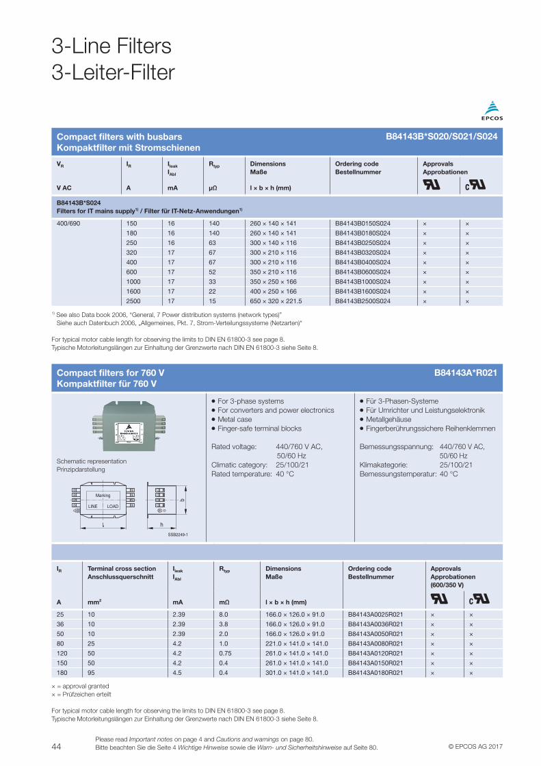
44 © EPCOS AG 2017Please read Important notes on page 4 and Cautions and warnings on page 80.Bitte beachten Sie die Seite 4 Wichtige Hinweise sowie die Warn- und Sicherheitshinweise auf Seite 80.
Compact filters with busbarsKompaktfilter mit Stromschienen
VR IR Ileak
IAbl
Rtyp DimensionsMaße
Ordering codeBestellnummer
ApprovalsApprobationen
V AC A mA µΩ l × b × h (mm)
B84143B*S024Filters for IT mains supply1) / Filter für IT-Netz-Anwendungen1)
400/690 150 16 140 260 × 140 × 141 B84143B0150S024 × ×
180 16 140 260 × 140 × 141 B84143B0180S024 × ×
250 16 63 300 × 140 × 116 B84143B0250S024 × ×
320 17 67 300 × 210 × 116 B84143B0320S024 × ×
400 17 67 300 × 210 × 116 B84143B0400S024 × ×
600 17 52 350 × 210 × 116 B84143B0600S024 × ×
1000 17 33 350 × 250 × 166 B84143B1000S024 × ×
1600 17 22 400 × 250 × 166 B84143B1600S024 × ×
2500 17 15 650 × 320 × 221.5 B84143B2500S024 × ×
1) See also Data book 2006, “General, 7 Power distribution systems (network types)” Siehe auch Datenbuch 2006, „Allgemeines, Pkt. 7, Strom-Verteilungssysteme (Netzarten)“
For typical motor cable length for observing the limits to DIN EN 61800-3 see page 8.Typische Motorleitungslängen zur Einhaltung der Grenzwerte nach DIN EN 61800-3 siehe Seite 8.
B84143B*S020/S021/S024
3-Line Filters3-Leiter-Filter
Compact filters for 760 VKompaktfilter für 760 V
VV For 3-phase systemsVV For converters and power electronicsVV Metal caseVV Finger-safe terminal blocks
Rated voltage: 440/760 V AC, 50/60 HzClimatic category: 25/100/21Rated temperature: 40 °C
VV Für 3-Phasen-SystemeVV Für Umrichter und LeistungselektronikVV MetallgehäuseVV Fingerberührungssichere Reihenklemmen
Bemessungsspannung: 440/760 V AC, 50/60 HzKlimakategorie: 25/100/21Bemessungstemperatur: 40 °C
Schematic representationPrinzipdarstellung
LINE LOAD
Marking
SSB2249-1
h
b
IR Terminal cross section Anschlussquerschnitt
Ileak
IAbl
Rtyp DimensionsMaße
Ordering codeBestellnummer
ApprovalsApprobationen (600/350 V)
A mm2 mA mΩ l × b × h (mm)
25 10 2.39 8.0 166.0 × 126.0 × 91.0 B84143A0025R021 × ×
36 10 2.39 3.8 166.0 × 126.0 × 91.0 B84143A0036R021 × ×
50 10 2.39 2.0 166.0 × 126.0 × 91.0 B84143A0050R021 × ×
80 25 4.2 1.0 221.0 × 141.0 × 141.0 B84143A0080R021 × ×
120 50 4.2 0.75 261.0 × 141.0 × 141.0 B84143A0120R021 × ×
150 50 4.2 0.4 261.0 × 141.0 × 141.0 B84143A0150R021 × ×
180 95 4.5 0.4 301.0 × 141.0 × 141.0 B84143A0180R021 × ×
× = approval granted× = Prüfzeichen erteilt
For typical motor cable length for observing the limits to DIN EN 61800-3 see page 8.Typische Motorleitungslängen zur Einhaltung der Grenzwerte nach DIN EN 61800-3 siehe Seite 8.
B84143A*R021
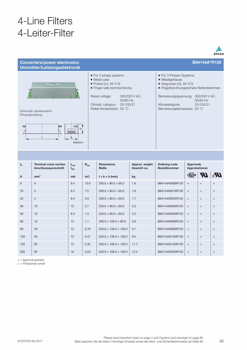
45© EPCOS AG 2017Please read Important notes on page 4 and Cautions and warnings on page 80.
Bitte beachten Sie die Seite 4 Wichtige Hinweise sowie die Warn- und Sicherheitshinweise auf Seite 80.
Converters/power electronicsUmrichter/Leistungselektronik
VV For 3-phase systemsVV Metal caseVV Potted (UL 94 V-0)VV Finger-safe terminal blocks
Rated voltage: 300/520 V AC, 50/60 HzClimatic category: 25/100/21Rated temperature: 50 °C
VV Für 3-Phasen-SystemeVV MetallgehäuseVV Vergossen (UL 94 V-0)VV Fingerberührungssichere Reihenklemmen
Bemessungsspannung: 300/520 V AC, 50/60 HzKlimakategorie: 25/100/21Bemessungstemperatur: 50 °C
Schematic representationPrinzipdarstellung
b
SSB2250-4
h
IR Terminal cross section Anschlussquerschnitt
Ileak
IAbl
Rtyp DimensionsMaße
Approx. weightGewicht ca.
Ordering codeBestellnummer
ApprovalsApprobationen
A mm2 mA mΩ l × b × h (mm) kg
8 4 9.4 13.6 200.0 × 80.0 × 60.0 1.6 B84144A0008R120 × × ×
16 4 9.4 7.5 200.0 × 80.0 × 60.0 1.6 B84144A0016R120 × × ×
25 4 9.4 3.9 200.0 × 80.0 × 60.0 1.7 B84144A0025R120 × × ×
36 10 13 2.7 230.0 × 90.0 × 60.0 2.2 B84144A0036R120 × × ×
50 10 9.4 1.3 230.0 × 90.0 × 60.0 2.2 B84144A0050R120 × × ×
66 16 13 1.1 260.0 × 100.0 × 80.0 3.6 B84144A0066R120 × × ×
90 25 13 0.76 250.0 × 130.0 × 100.0 5.1 B84144A0090R120 × × ×
120 50 13 0.47 250.0 × 130.0 × 130.0 9.5 B84144A0120R120 × × ×
150 95 13 0.32 250.0 × 160.0 × 130.0 11.7 B84144A0150R120 × × ×
200 95 16 0.23 250.0 × 160.0 × 130.0 12.5 B84144A0200R120 × × ×
× = approval granted× = Prüfzeichen erteilt
B84144A*R120
4-Line Filters4-Leiter-Filter
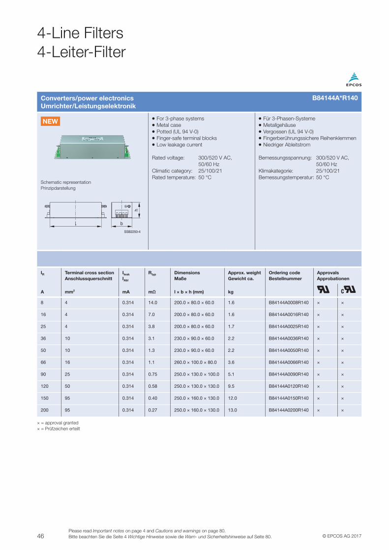
46 © EPCOS AG 2017Please read Important notes on page 4 and Cautions and warnings on page 80.Bitte beachten Sie die Seite 4 Wichtige Hinweise sowie die Warn- und Sicherheitshinweise auf Seite 80.
4-Line Filters4-Leiter-Filter
Converters/power electronicsUmrichter/Leistungselektronik
VV For 3-phase systemsVV Metal caseVV Potted (UL 94 V-0)VV Finger-safe terminal blocksVV Low leakage current
Rated voltage: 300/520 V AC, 50/60 HzClimatic category: 25/100/21Rated temperature: 50 °C
VV Für 3-Phasen-SystemeVV MetallgehäuseVV Vergossen (UL 94 V-0)VV Fingerberührungssichere ReihenklemmenVV Niedriger Ableitstrom
Bemessungsspannung: 300/520 V AC, 50/60 HzKlimakategorie: 25/100/21Bemessungstemperatur: 50 °C
Schematic representationPrinzipdarstellung
b
SSB2250-4
h
IR Terminal cross section Anschlussquerschnitt
Ileak
IAbl
Rtyp DimensionsMaße
Approx. weightGewicht ca.
Ordering codeBestellnummer
ApprovalsApprobationen
A mm2 mA mΩ l × b × h (mm) kg
8 4 0.314 14.0 200.0 × 80.0 × 60.0 1.6 B84144A0008R140 × ×
16 4 0.314 7.0 200.0 × 80.0 × 60.0 1.6 B84144A0016R140 × ×
25 4 0.314 3.8 200.0 × 80.0 × 60.0 1.7 B84144A0025R140 × ×
36 10 0.314 3.1 230.0 × 90.0 × 60.0 2.2 B84144A0036R140 × ×
50 10 0.314 1.3 230.0 × 90.0 × 60.0 2.2 B84144A0050R140 × ×
66 16 0.314 1.1 260.0 × 100.0 × 80.0 3.6 B84144A0066R140 × ×
90 25 0.314 0.75 250.0 × 130.0 × 100.0 5.1 B84144A0090R140 × ×
120 50 0.314 0.58 250.0 × 130.0 × 130.0 9.5 B84144A0120R140 × ×
150 95 0.314 0.40 250.0 × 160.0 × 130.0 12.0 B84144A0150R140 × ×
200 95 0.314 0.27 250.0 × 160.0 × 130.0 13.0 B84144A0200R140 × ×
× = approval granted× = Prüfzeichen erteilt
B84144A*R140
NEW
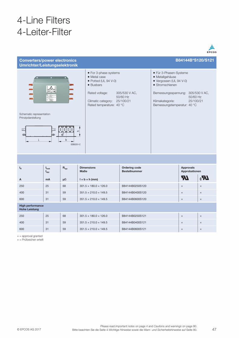
47© EPCOS AG 2017Please read Important notes on page 4 and Cautions and warnings on page 80.
Bitte beachten Sie die Seite 4 Wichtige Hinweise sowie die Warn- und Sicherheitshinweise auf Seite 80.
Converters/power electronicsUmrichter/Leistungselektronik
VV For 3-phase systemsVV Metal caseVV Potted (UL 94 V-0)VV Busbars
Rated voltage: 305/530 V AC, 50/60 HzClimatic category: 25/100/21Rated temperature: 40 °C
VV Für 3-Phasen-SystemeVV MetallgehäuseVV Vergossen (UL 94 V-0)VV Stromschienen
Bemessungsspannung: 305/530 V AC, 50/60 HzKlimakategorie: 25/100/21Bemessungstemperatur: 40 °C
Schematic representationPrinzipdarstellung
SSB2251-C
h
b
IR Ileak
IAbl
Rtyp DimensionsMaße
Ordering codeBestellnummer
ApprovalsApprobationen
A mA µΩ l × b × h (mm)
250 25 68 301.5 × 180.0 × 126.0 B84144B0250S120 × ×
400 31 59 351.5 × 210.0 × 149.5 B84144B0400S120 × ×
600 31 59 351.5 × 210.0 × 149.5 B84144B0600S120 × ×
High performanceHohe Leistung
250 25 68 301.5 × 180.0 × 126.0 B84144B0250S121 × ×
400 31 59 351.5 × 210.0 × 149.5 B84144B0400S121 × ×
600 31 59 351.5 × 210.0 × 149.5 B84144B0600S121 × ×
× = approval granted× = Prüfzeichen erteilt
B84144B*S120/S121
4-Line Filters4-Leiter-Filter
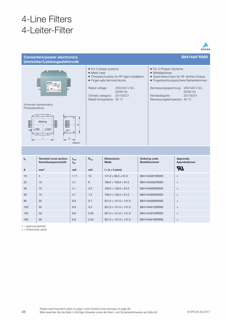
48 © EPCOS AG 2017Please read Important notes on page 4 and Cautions and warnings on page 80.Bitte beachten Sie die Seite 4 Wichtige Hinweise sowie die Warn- und Sicherheitshinweise auf Seite 80.
4-Line Filters4-Leiter-Filter
Converters/power electronicsUmrichter/Leistungselektronik
VV For 3-phase systemsVV Metal caseVV Threaded bushes for RF-tight installationVV Finger-safe terminal blocks
Rated voltage: 250/440 V AC, 50/60 HzClimatic category: 25/100/21Rated temperature: 40 °C
VV Für 3-Phasen-SystemeVV MetallgehäuseVV Gewindebuchsen für HF-dichten EinbauVV Fingerberührungssichere Reihenklemmen
Bemessungsspannung: 250/440 V AC, 50/60 HzKlimakategorie: 25/100/21Bemessungstemperatur: 40 °C
Schematic representationPrinzipdarstellung
SSB2252-K
Marking
LOADLINE
h
b
IR Terminal cross section Anschlussquerschnitt
Ileak
IAbl
Rtyp DimensionsMaße
Ordering codeBestellnummer
ApprovalsApprobationen
A mm2 mA mΩ l × b × h (mm)
16 4 1.11 10 141.0 × 86.0 × 81.0 B84144A0016R000 ×
25 10 4.1 6 166.0 × 126.0 × 91.0 B84144A0025R000 ×
36 10 4.1 3.5 166.0 × 126.0 × 91.0 B84144A0036R000 ×
50 10 4.1 1.3 166.0 × 126.0 × 91.0 B84144A0050R000 ×
80 25 8.8 0.7 221.0 × 141.0 × 141.0 B84144A0080R000 ×
120 50 8.8 0.5 261.0 × 141.0 × 141.0 B84144A0120R000 ×
150 50 8.8 0.35 261.0 × 141.0 × 141.0 B84144A0150R000 ×
180 95 8.8 0.25 301.0 × 141.0 × 141.0 B84144A0180R000 ×
× = approval granted× = Prüfzeichen erteilt
B84144A*R000
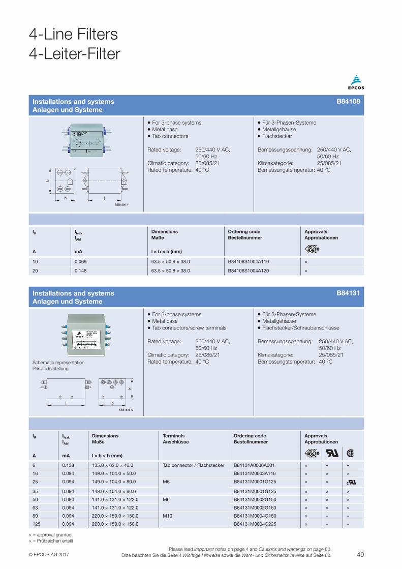
49© EPCOS AG 2017Please read Important notes on page 4 and Cautions and warnings on page 80.
Bitte beachten Sie die Seite 4 Wichtige Hinweise sowie die Warn- und Sicherheitshinweise auf Seite 80.
Installations and systemsAnlagen und Systeme
VV For 3-phase systemsVV Metal caseVV Tab connectors/screw terminals
Rated voltage: 250/440 V AC, 50/60 HzClimatic category: 25/085/21Rated temperature: 40 °C
VV Für 3-Phasen-SystemeVV MetallgehäuseVV Flachstecker/Schraubanschlüsse
Bemessungsspannung: 250/440 V AC, 50/60 HzKlimakategorie: 25/085/21Bemessungstemperatur: 40 °CSchematic representation
Prinzipdarstellung
SSB1898-Q
h
b
IR Ileak
IAbl
DimensionsMaße
TerminalsAnschlüsse
Ordering codeBestellnummer
ApprovalsApprobationen
A mA l × b × h (mm)
6 0.138 135.0 × 62.0 × 46.0 Tab connector / Flachstecker B84131A0006A001 × – –
16 0.094 149.0 × 104.0 × 50.0 B84131M0003A116 × × ×
25 0.094 149.0 × 104.0 × 80.0 M6 B84131M0001G125 × ×
35 0.094 149.0 × 104.0 × 80.0 B84131M0001G135 × × ×
50 0.094 141.0 × 131.0 × 122.0 M6 B84131M0002G150 × × ×
63 0.094 141.0 × 131.0 × 122.0 B84131M0002G163 × × ×
80 0.094 220.0 × 150.0 × 150.0 M10 B84131M0004G180 × – –
125 0.094 220.0 × 150.0 × 150.0 B84131M0004G225 × – –
× = approval granted× = Prüfzeichen erteilt
Installations and systemsAnlagen und Systeme
VV For 3-phase systemsVV Metal caseVV Tab connectors
Rated voltage: 250/440 V AC, 50/60 HzClimatic category: 25/085/21Rated temperature: 40 °C
VV Für 3-Phasen-SystemeVV MetallgehäuseVV Flachstecker
Bemessungsspannung: 250/440 V AC, 50/60 HzKlimakategorie: 25/085/21Bemessungstemperatur: 40 °C
SSB1899-Y
b
h
IR Ileak
IAbl
DimensionsMaße
Ordering codeBestellnummer
ApprovalsApprobationen
A mA l × b × h (mm)
10 0.069 63.5 × 50.8 × 38.0 B84108S1004A110 ×
20 0.148 63.5 × 50.8 × 38.0 B84108S1004A120 ×
B84131
B84108
4-Line Filters4-Leiter-Filter
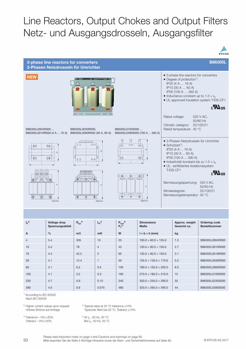
50 © EPCOS AG 2017Please read Important notes on page 4 and Cautions and warnings on page 80.Bitte beachten Sie die Seite 4 Wichtige Hinweise sowie die Warn- und Sicherheitshinweise auf Seite 80.
Line Reactors, Output Chokes and Output FiltersNetz- und Ausgangsdrosseln, Ausgangsfilter
3-phase line reactors for converters3-Phasen Netzdrosseln für Umrichter
VV 3-phase line reactors for convertersVV Degree of protection1): IP20 (4 A … 16 A) IP10 (30 A … 60 A) IP00 (100 A … 390 A)VV Inductance constant up to 1.5 × IRVV UL approved insulation system T-EIS-CF1
Rated voltage: 520 V AC, 50/60 HzClimatic category: 25/100/21Rated temperature: 40 °CB86305L0004R000 ...
B86305L0016R000 (4 A ... 16 A)B86305L0030R000, B86305L0060R000 (30 A, 60 A)
B86305L0100S000 ... B86305L0390S000 (100 A ... 390 A)
hb
SSB2728-9
h
E1 E2 E3S1 S2 S3
b
SSB2729-H
hb
SSB2730-K
VV 3-Phasen Netzdrosseln für UmrichterVV Schutzart1): IP20 (4 A ... 16 A) IP10 (30 A ... 60 A) IP00 (100 A ... 390 A)VV Induktivität konstant bis zu 1.5 × IRVV UL- zertifiziertes Isolationssystem T-EIS-CF1
Bemessungsspannung: 520 V AC, 50/60 HzKlimakategorie: 25/100/21Bemessungstemperatur: 40 °C
IR2) Voltage drop
SpannungsabfallRtyp
3) LR4) Ploss
5)
PV5)
DimensionsMaße
Approx. weightGewicht ca.
Ordering codeBestellnummer
A % mΩ mH W l × b × h (mm) kg
4 5.4 335 10 25 100.0 × 60.0 × 135.0 1.3 B86305L0004R000
10 5.4 78 4 43 130.0 × 90.0 × 150.0 2.7 B86305L0010R000
16 4.4 42.2 2 65 130.0 × 90.0 × 150.0 3.1 B86305L0016R000
30 4.1 12.4 1 50 155.0 × 135.0 × 170.0 5.5 B86305L0030R000
60 4.1 6.2 0.5 100 180.0 × 150.0 × 205.0 8.5 B86305L0060R000
100 4.1 3.2 0.3 160 270.0 × 180.0 × 210.0 15 B86305L0100S000
230 4.7 0.9 0.15 340 320.0 × 235.0 × 290.0 32 B86305L0230S000
390 4.0 0.6 0.075 480 320.0 × 265.0 × 290.0 44 B86305L0390S000
1) According to IEC 60529 Nach IEC 60529
2) Higher current values upon request 3) Typical value at 20 °C tolerance ±10% Höhere Ströme auf Anfrage Typischer Wert bei 20 °C, Toleranz ±10%
4) Tolerance – 0%/+20% 5) At IR , 50 Hz, 20 °C Toleranz – 0%/+20% Bei IR , 50 Hz, 20 °C
B86305L
NEW
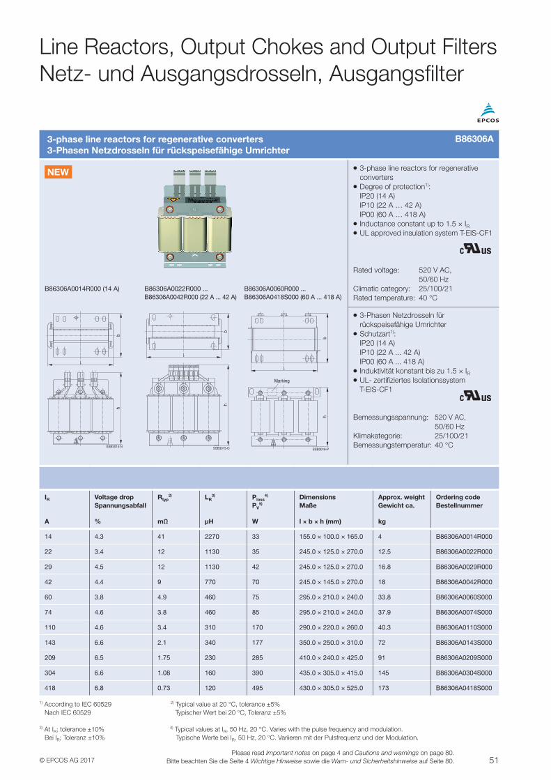
51© EPCOS AG 2017Please read Important notes on page 4 and Cautions and warnings on page 80.
Bitte beachten Sie die Seite 4 Wichtige Hinweise sowie die Warn- und Sicherheitshinweise auf Seite 80.
Line Reactors, Output Chokes and Output FiltersNetz- und Ausgangsdrosseln, Ausgangsfilter
3-phase line reactors for regenerative converters3-Phasen Netzdrosseln für rückspeisefähige Umrichter
VV 3-phase line reactors for regenerative convertersVV Degree of protection1): IP20 (14 A) IP10 (22 A … 42 A) IP00 (60 A … 418 A)VV Inductance constant up to 1.5 × IRVV UL approved insulation system T-EIS-CF1
Rated voltage: 520 V AC, 50/60 HzClimatic category: 25/100/21Rated temperature: 40 °C
B86306A0014R000 (14 A) B86306A0022R000 ... B86306A0042R000 (22 A ... 42 A)
B86306A0060R000 ... B86306A0418S000 (60 A ... 418 A)
VV 3-Phasen Netzdrosseln für rückspeisefähige UmrichterVV Schutzart1): IP20 (14 A) IP10 (22 A ... 42 A) IP00 (60 A ... 418 A)VV Induktivität konstant bis zu 1.5 × IRVV UL- zertifiziertes Isolationssystem T-EIS-CF1
Bemessungsspannung: 520 V AC, 50/60 HzKlimakategorie: 25/100/21Bemessungstemperatur: 40 °C
IR Voltage dropSpannungsabfall
Rtyp2) LR
3) Ploss4)
PV5)
DimensionsMaße
Approx. weightGewicht ca.
Ordering codeBestellnummer
A % mΩ µH W l × b × h (mm) kg
14 4.3 41 2270 33 155.0 × 100.0 × 165.0 4 B86306A0014R000
22 3.4 12 1130 35 245.0 × 125.0 × 270.0 12.5 B86306A0022R000
29 4.5 12 1130 42 245.0 × 125.0 × 270.0 16.8 B86306A0029R000
42 4.4 9 770 70 245.0 × 145.0 × 270.0 18 B86306A0042R000
60 3.8 4.9 460 75 295.0 × 210.0 × 240.0 33.8 B86306A0060S000
74 4.6 3.8 460 85 295.0 × 210.0 × 240.0 37.9 B86306A0074S000
110 4.6 3.4 310 170 290.0 × 220.0 × 260.0 40.3 B86306A0110S000
143 6.6 2.1 340 177 350.0 × 250.0 × 310.0 72 B86306A0143S000
209 6.5 1.75 230 285 410.0 × 240.0 × 425.0 91 B86306A0209S000
304 6.6 1.08 160 390 435.0 × 305.0 × 415.0 145 B86306A0304S000
418 6.8 0.73 120 495 430.0 × 305.0 × 525.0 173 B86306A0418S000
1) According to IEC 60529 2) Typical value at 20 °C, tolerance ±5% Nach IEC 60529 Typischer Wert bei 20 °C, Toleranz ±5%
3) At IR; tolerance ±10% 4) Typical values at IR, 50 Hz, 20 °C. Varies with the pulse frequency and modulation. Bei IR; Toleranz ±10% Typische Werte bei IR, 50 Hz, 20 °C. Variieren mit der Pulsfrequenz und der Modulation.
B86306A
NEW
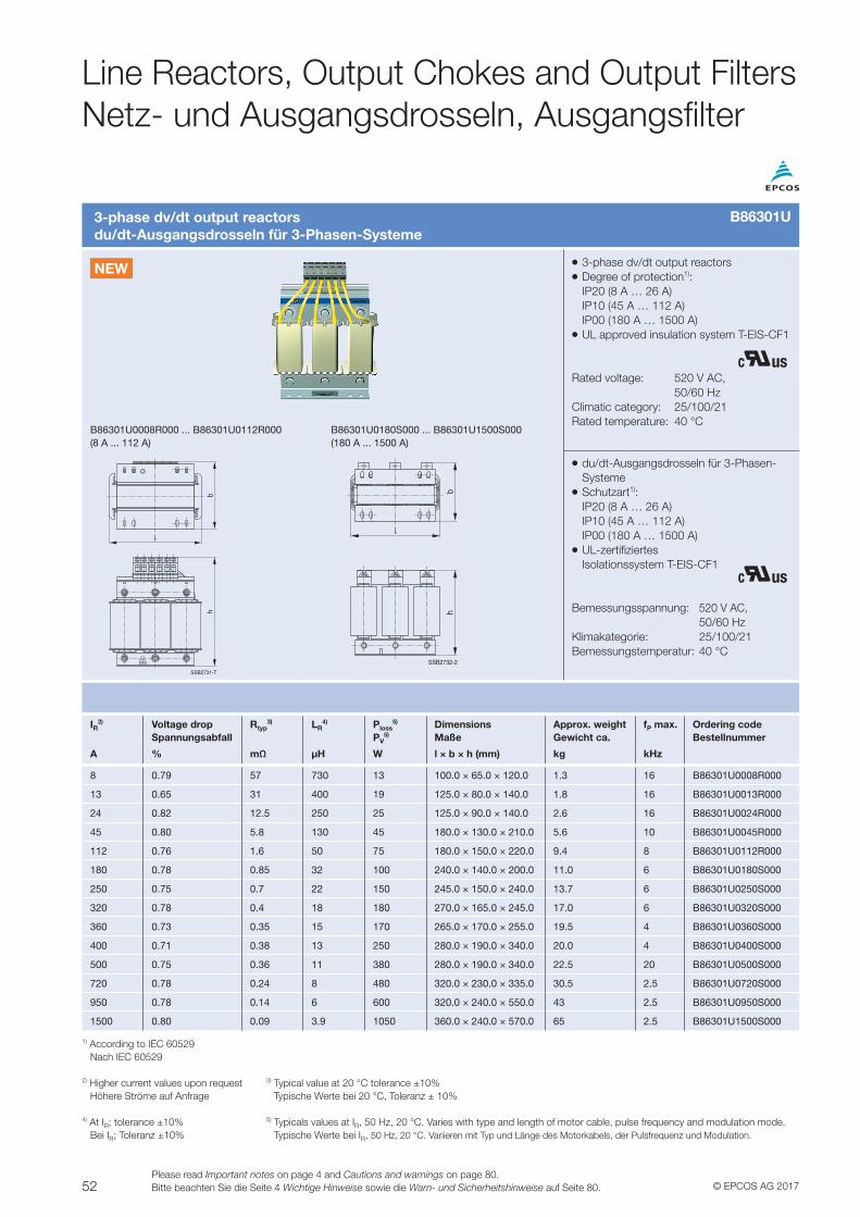
52 © EPCOS AG 2017Please read Important notes on page 4 and Cautions and warnings on page 80.Bitte beachten Sie die Seite 4 Wichtige Hinweise sowie die Warn- und Sicherheitshinweise auf Seite 80.
Line Reactors, Output Chokes and Output FiltersNetz- und Ausgangsdrosseln, Ausgangsfilter
3-phase dv/dt output reactorsdu/dt-Ausgangsdrosseln für 3-Phasen-Systeme
VV 3-phase dv/dt output reactorsVV Degree of protection1): IP20 (8 A … 26 A) IP10 (45 A … 112 A) IP00 (180 A … 1500 A)VV UL approved insulation system T-EIS-CF1
Rated voltage: 520 V AC, 50/60 HzClimatic category: 25/100/21Rated temperature: 40 °C
B86301U0008R000 ... B86301U0112R000 (8 A ... 112 A)
B86301U0180S000 ... B86301U1500S000 (180 A ... 1500 A)
hb
E1 S1 E2 S2 E3 S3
SSB2731-T
hb
SSB2732-2
VV du/dt-Ausgangsdrosseln für 3-Phasen-SystemeVV Schutzart1): IP20 (8 A … 26 A) IP10 (45 A … 112 A) IP00 (180 A … 1500 A)VV UL-zertifiziertes Isolationssystem T-EIS-CF1
Bemessungsspannung: 520 V AC, 50/60 HzKlimakategorie: 25/100/21Bemessungstemperatur: 40 °C
IR2) Voltage drop
SpannungsabfallRtyp
3) LR4) Ploss
5)
PV5)
DimensionsMaße
Approx. weightGewicht ca.
fP max. Ordering codeBestellnummer
A % mΩ µH W l × b × h (mm) kg kHz
8 0.79 57 730 13 100.0 × 65.0 × 120.0 1.3 16 B86301U0008R000
13 0.65 31 400 19 125.0 × 80.0 × 140.0 1.8 16 B86301U0013R000
24 0.82 12.5 250 25 125.0 × 90.0 × 140.0 2.6 16 B86301U0024R000
45 0.80 5.8 130 45 180.0 × 130.0 × 210.0 5.6 10 B86301U0045R000
112 0.76 1.6 50 75 180.0 × 150.0 × 220.0 9.4 8 B86301U0112R000
180 0.78 0.85 32 100 240.0 × 140.0 × 200.0 11.0 6 B86301U0180S000
250 0.75 0.7 22 150 245.0 × 150.0 × 240.0 13.7 6 B86301U0250S000
320 0.78 0.4 18 180 270.0 × 165.0 × 245.0 17.0 6 B86301U0320S000
360 0.73 0.35 15 170 265.0 × 170.0 × 255.0 19.5 4 B86301U0360S000
400 0.71 0.38 13 250 280.0 × 190.0 × 340.0 20.0 4 B86301U0400S000
500 0.75 0.36 11 380 280.0 × 190.0 × 340.0 22.5 20 B86301U0500S000
720 0.78 0.24 8 480 320.0 × 230.0 × 335.0 30.5 2.5 B86301U0720S000
950 0.78 0.14 6 600 320.0 × 240.0 × 550.0 43 2.5 B86301U0950S000
1500 0.80 0.09 3.9 1050 360.0 × 240.0 × 570.0 65 2.5 B86301U1500S000
1) According to IEC 60529 Nach IEC 60529
2) Higher current values upon request 3) Typical value at 20 °C tolerance ±10% Höhere Ströme auf Anfrage Typische Werte bei 20 °C, Toleranz ± 10%
4) At IR; tolerance ±10% 5) Typicals values at IR, 50 Hz, 20 °C. Varies with type and length of motor cable, pulse frequency and modulation mode. Bei IR; Toleranz ±10% Typische Werte bei IR, 50 Hz, 20 °C. Variieren mit Typ und Länge des Motorkabels, der Pulsfrequenz und Modulation.
B86301U
NEW
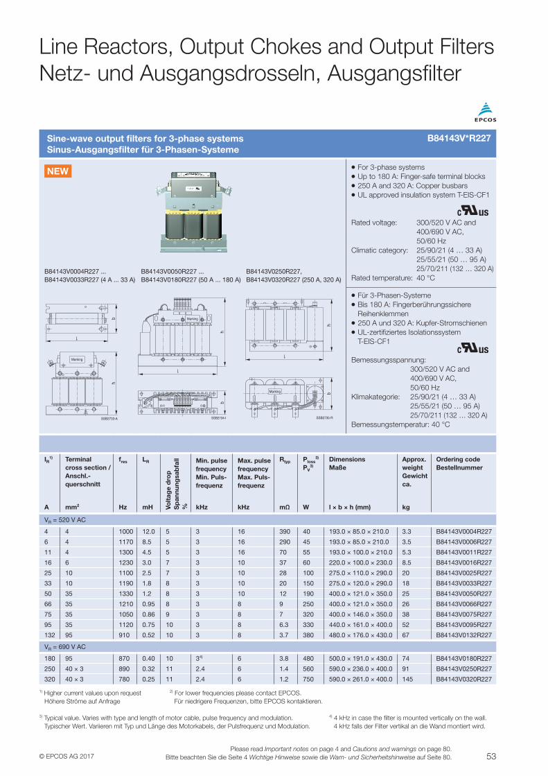
53© EPCOS AG 2017Please read Important notes on page 4 and Cautions and warnings on page 80.
Bitte beachten Sie die Seite 4 Wichtige Hinweise sowie die Warn- und Sicherheitshinweise auf Seite 80.
Sine-wave output filters for 3-phase systemsSinus-Ausgangsfilter für 3-Phasen-Systeme
VV For 3-phase systemsVV Up to 180 A: Finger-safe terminal blocksVV 250 A and 320 A: Copper busbarsVV UL approved insulation system T-EIS-CF1
Rated voltage: 300/520 V AC and 400/690 V AC, 50/60 HzClimatic category: 25/90/21 (4 … 33 A) 25/55/21 (50 … 95 A) 25/70/211 (132 … 320 A)Rated temperature: 40 °C
B84143V0004R227 ... B84143V0033R227 (4 A ... 33 A)
B84143V0050R227 ... B84143V0180R227 (50 A ... 180 A)
B84143V0250R227, B84143V0320R227 (250 A, 320 A)
hb
Marking
SSB2733-A
h
Marking
b
SSB2734-I
hbMarking
SSB2735-R
VV Für 3-Phasen-SystemeVV Bis 180 A: Fingerberührungssichere ReihenklemmenVV 250 A und 320 A: Kupfer-StromschienenVV UL-zertifiziertes Isolationssystem T-EIS-CF1
Bemessungsspannung: 300/520 V AC and 400/690 V AC, 50/60 HzKlimakategorie: 25/90/21 (4 … 33 A) 25/55/21 (50 … 95 A) 25/70/211 (132 … 320 A)Bemessungstemperatur: 40 °C
IR1) Terminal
cross section / Anschl.-querschnitt
fres LR
Volt
age
dro
pS
pan
nung
sab
fall
%
Min. pulse frequencyMin. Puls-frequenz
Max. pulse frequencyMax. Puls-frequenz
Rtyp Ploss3)
PV3)
DimensionsMaße
Approx. weightGewicht ca.
Ordering codeBestellnummer
A mm2 Hz mH kHz kHz mΩ W l × b × h (mm) kg
VR = 520 V AC
4 4 1000 12.0 5 3 16 390 40 193.0 × 85.0 × 210.0 3.3 B84143V0004R227
6 4 1170 8.5 5 3 16 290 45 193.0 × 85.0 × 210.0 3.5 B84143V0006R227
11 4 1300 4.5 5 3 16 70 55 193.0 × 100.0 × 210.0 5.3 B84143V0011R227
16 6 1230 3.0 7 3 10 37 60 220.0 × 100.0 × 230.0 8.5 B84143V0016R227
25 10 1100 2.5 7 3 10 28 100 275.0 × 110.0 × 290.0 20 B84143V0025R227
33 10 1190 1.8 8 3 10 20 150 275.0 × 120.0 × 290.0 18 B84143V0033R227
50 35 1330 1.2 8 3 10 12 190 400.0 × 121.0 × 350.0 25 B84143V0050R227
66 35 1210 0.95 8 3 8 9 250 400.0 × 121.0 × 350.0 26 B84143V0066R227
75 35 1050 0.86 9 3 8 7 320 400.0 × 146.0 × 350.0 38 B84143V0075R227
95 35 1120 0.75 10 3 8 6.3 330 440.0 × 161.0 × 400.0 52 B84143V0095R227
132 95 910 0.52 10 3 8 3.7 380 480.0 × 176.0 × 430.0 67 B84143V0132R227
VR = 690 V AC
180 95 870 0.40 10 34) 6 3.8 480 500.0 × 191.0 × 430.0 74 B84143V0180R227
250 40 × 3 890 0.32 11 2.4 6 1.4 560 590.0 × 236.0 × 400.0 91 B84143V0250R227
320 40 × 3 780 0.25 11 2.4 6 1.2 750 590.0 × 261.0 × 400.0 145 B84143V0320R227
1) Higher current values upon request 2) For lower frequencies please contact EPCOS. Höhere Ströme auf Anfrage Für niedrigere Frequenzen, bitte EPCOS kontaktieren.
3) Typical value. Varies with type and length of motor cable, pulse frequency and modulation. 4) 4 kHz in case the filter is mounted vertically on the wall. Typischer Wert. Variieren mit Typ und Länge des Motorkabels, der Pulsfrequenz und Modulation. 4 kHz falls der Filter vertikal an die Wand montiert wird.
Line Reactors, Output Chokes and Output FiltersNetz- und Ausgangsdrosseln, Ausgangsfilter
B84143V*R227
NEW
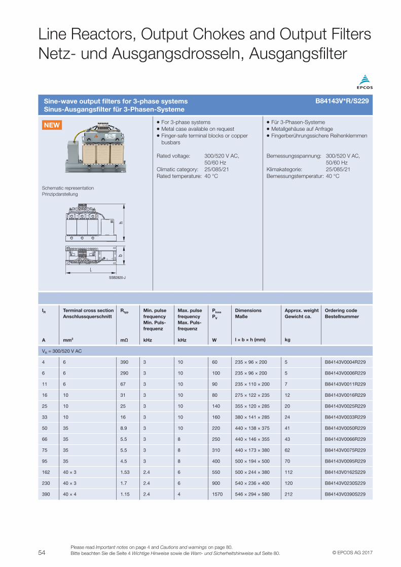
54 © EPCOS AG 2017Please read Important notes on page 4 and Cautions and warnings on page 80.Bitte beachten Sie die Seite 4 Wichtige Hinweise sowie die Warn- und Sicherheitshinweise auf Seite 80.
Line Reactors, Output Chokes and Output FiltersNetz- und Ausgangsdrosseln, Ausgangsfilter
Sine-wave output filters for 3-phase systemsSinus-Ausgangsfilter für 3-Phasen-Systeme
VV For 3-phase systemsVV Metal case available on requestVV Finger-safe terminal blocks or copper busbars
Rated voltage: 300/520 V AC, 50/60 HzClimatic category: 25/085/21Rated temperature: 40 °C
VV Für 3-Phasen-SystemeVV Metallgehäuse auf AnfrageVV Fingerberührungssichere Reihenklemmen
Bemessungsspannung: 300/520 V AC, 50/60 HzKlimakategorie: 25/085/21Bemessungstemperatur: 40 °C
Schematic representationPrinzipdarstellung
SSB2820-J
hb
IR Terminal cross section Anschlussquerschnitt
Rtyp Min. pulse frequencyMin. Puls-frequenz
Max. pulse frequencyMax. Puls-frequenz
Ploss
PV
DimensionsMaße
Approx. weightGewicht ca.
Ordering codeBestellnummer
A mm2 mΩ kHz kHz W l × b × h (mm) kg
VR = 300/520 V AC
4 6 390 3 10 60 235 × 96 × 200 5 B84143V0004R229
6 6 290 3 10 100 235 × 96 × 200 5 B84143V0006R229
11 6 67 3 10 90 235 × 110 × 200 7 B84143V0011R229
16 10 31 3 10 80 275 × 122 × 235 12 B84143V0016R229
25 10 25 3 10 140 355 × 120 × 285 20 B84143V0025R229
33 10 16 3 10 160 380 × 141 × 285 24 B84143V0033R229
50 35 8.9 3 10 220 440 × 138 × 375 41 B84143V0050R229
66 35 5.5 3 8 250 440 × 146 × 355 43 B84143V0066R229
75 35 5.5 3 8 310 440 × 173 × 380 62 B84143V0075R229
95 35 4.5 3 8 400 500 × 194 × 500 70 B84143V0095R229
162 40 × 3 1.53 2.4 6 550 500 × 244 × 380 112 B84143V0162S229
230 40 × 3 1.7 2.4 6 900 540 × 236 × 400 120 B84143V0230S229
390 40 × 4 1.15 2.4 4 1570 546 × 294 × 580 212 B84143V0390S229
B84143V*R/S229
NEW
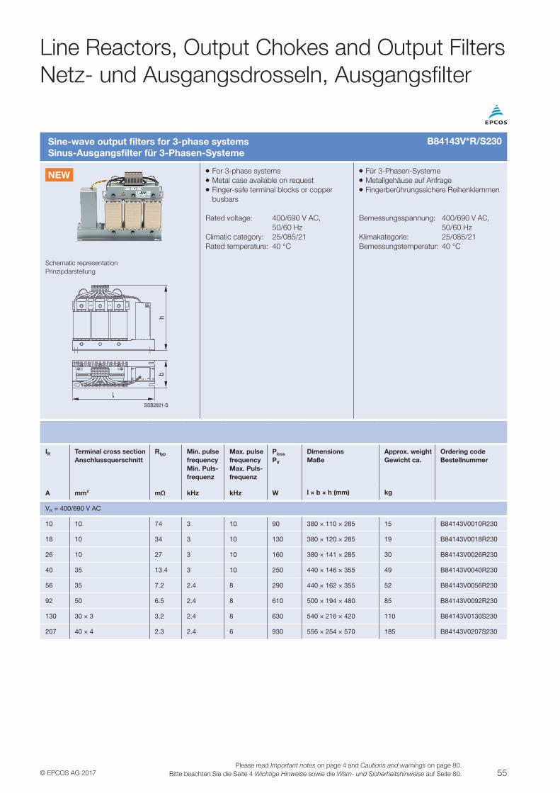
55© EPCOS AG 2017Please read Important notes on page 4 and Cautions and warnings on page 80.
Bitte beachten Sie die Seite 4 Wichtige Hinweise sowie die Warn- und Sicherheitshinweise auf Seite 80.
Line Reactors, Output Chokes and Output FiltersNetz- und Ausgangsdrosseln, Ausgangsfilter
Sine-wave output filters for 3-phase systemsSinus-Ausgangsfilter für 3-Phasen-Systeme
VV For 3-phase systemsVV Metal case available on requestVV Finger-safe terminal blocks or copper busbars
Rated voltage: 400/690 V AC, 50/60 HzClimatic category: 25/085/21Rated temperature: 40 °C
VV Für 3-Phasen-SystemeVV Metallgehäuse auf AnfrageVV Fingerberührungssichere Reihenklemmen
Bemessungsspannung: 400/690 V AC, 50/60 HzKlimakategorie: 25/085/21Bemessungstemperatur: 40 °C
Schematic representationPrinzipdarstellung
SSB2821-S
bh
IR Terminal cross section Anschlussquerschnitt
Rtyp Min. pulse frequencyMin. Puls-frequenz
Max. pulse frequencyMax. Puls-frequenz
Ploss
PV
DimensionsMaße
Approx. weightGewicht ca.
Ordering codeBestellnummer
A mm2 mΩ kHz kHz W l × b × h (mm) kg
VR = 400/690 V AC
10 10 74 3 10 90 380 × 110 × 285 15 B84143V0010R230
18 10 34 3 10 130 380 × 120 × 285 19 B84143V0018R230
26 10 27 3 10 160 380 × 141 × 285 30 B84143V0026R230
40 35 13.4 3 10 250 440 × 146 × 355 49 B84143V0040R230
56 35 7.2 2.4 8 290 440 × 162 × 355 52 B84143V0056R230
92 50 6.5 2.4 8 610 500 × 194 × 480 85 B84143V0092R230
130 30 × 3 3.2 2.4 8 630 540 × 216 × 420 110 B84143V0130S230
207 40 × 4 2.3 2.4 6 930 556 × 254 × 570 185 B84143V0207S230
B84143V*R/S230
NEW
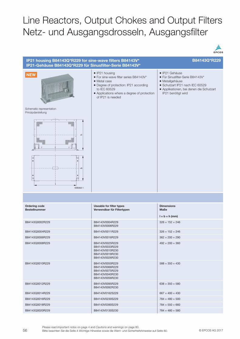
56 © EPCOS AG 2017Please read Important notes on page 4 and Cautions and warnings on page 80.Bitte beachten Sie die Seite 4 Wichtige Hinweise sowie die Warn- und Sicherheitshinweise auf Seite 80.
Line Reactors, Output Chokes and Output FiltersNetz- und Ausgangsdrosseln, Ausgangsfilter
IP21 housing B84143Q*R229 for sine-wave filters B84143V*IP21-Gehäuse B84143Q*R229 für Sinusfilter-Serie B84143V*
VV IP21 housingVV For sine-wave filter series B84143V*VV Metal caseVV Degree of protection: IP21 according to IEC 60529VV Applications where a degree of protection of IP21 is needed
VV IP21 GehäuseVV Für Sinusfilter-Serie B84143V*VV MetallgehäuseVV Schutzart IP21 nach IEC 60529VV Applikationen, bei denen die Schutzart IP21 benötigt wird
Schematic representationPrinzipdarstellung
SSB2822-1
hb
Ordering codeBestellnummer
Useable for filter typesVerwendbar für Filtertypen
DimensionsMaße
l × b × h (mm)
B84143Q0002R229 B84143V0004R229B84143V0006R229
326 × 152 × 246
B84143Q0004R229 B84143V0011R229 326 × 152 × 246
B84143Q0006R229 B84143V0016R229 362 × 200 × 290
B84143Q0008R229 B84143V0025R229B84143V0033R229B84143V0010R230B84143V0018R230B84143V0026R230
492 × 200 × 360
B84143Q0010R229 B84143V0050R229B84143V0066R229B84143V0075R229B84143V0040R230B84143V0056R230
588 × 350 × 430
B84143Q0012R229 B84143V0095R229B84143V0092R230
638 × 350 × 580
B84143Q0014R229 B84143V0162S229 667 × 400 × 430
B84143Q0016R229 B84143V0230S229 784 × 480 × 500
B84143Q0018R229 B84143V0390S229 784 × 550 × 660
B84143Q0020R229 B84143V0130S230 784 × 480 × 580
B84143Q*R229
NEW
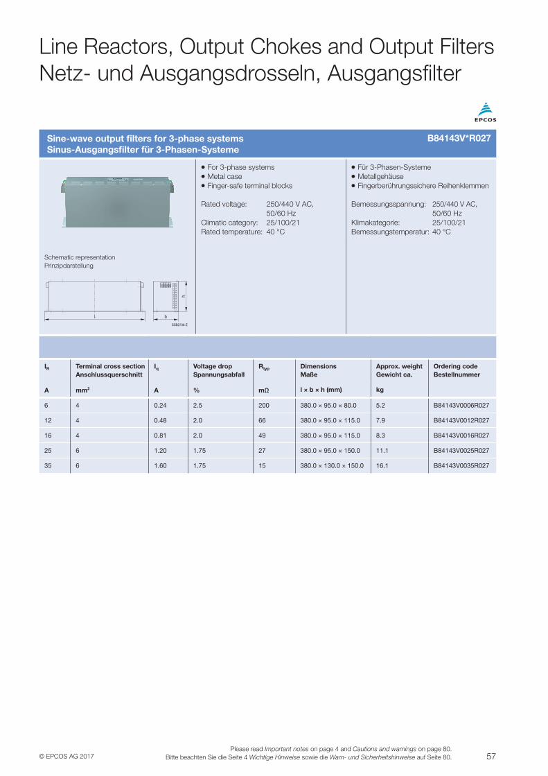
57© EPCOS AG 2017Please read Important notes on page 4 and Cautions and warnings on page 80.
Bitte beachten Sie die Seite 4 Wichtige Hinweise sowie die Warn- und Sicherheitshinweise auf Seite 80.
Line Reactors, Output Chokes and Output FiltersNetz- und Ausgangsdrosseln, Ausgangsfilter
Sine-wave output filters for 3-phase systemsSinus-Ausgangsfilter für 3-Phasen-Systeme
VV For 3-phase systemsVV Metal caseVV Finger-safe terminal blocks
Rated voltage: 250/440 V AC, 50/60 HzClimatic category: 25/100/21Rated temperature: 40 °C
VV Für 3-Phasen-SystemeVV MetallgehäuseVV Fingerberührungssichere Reihenklemmen
Bemessungsspannung: 250/440 V AC, 50/60 HzKlimakategorie: 25/100/21Bemessungstemperatur: 40 °C
Schematic representationPrinzipdarstellung
b
h
SSB2736-Z
IR Terminal cross section Anschlussquerschnitt
Iq Voltage dropSpannungsabfall
Rtyp DimensionsMaße
Approx. weightGewicht ca.
Ordering codeBestellnummer
A mm2 A % mΩ l × b × h (mm) kg
6 4 0.24 2.5 200 380.0 × 95.0 × 80.0 5.2 B84143V0006R027
12 4 0.48 2.0 66 380.0 × 95.0 × 115.0 7.9 B84143V0012R027
16 4 0.81 2.0 49 380.0 × 95.0 × 115.0 8.3 B84143V0016R027
25 6 1.20 1.75 27 380.0 × 95.0 × 150.0 11.1 B84143V0025R027
35 6 1.60 1.75 15 380.0 × 130.0 × 150.0 16.1 B84143V0035R027
B84143V*R027
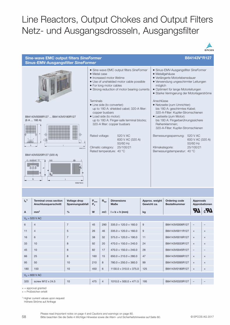
58 © EPCOS AG 2017Please read Important notes on page 4 and Cautions and warnings on page 80.Bitte beachten Sie die Seite 4 Wichtige Hinweise sowie die Warn- und Sicherheitshinweise auf Seite 80.
Line Reactors, Output Chokes and Output FiltersNetz- und Ausgangsdrosseln, Ausgangsfilter
Sine-wave EMC output filters SineFormerSinus-EMV-Ausgangsfilter SineFormer
VV Sine-wave EMC output filters SineFormerVV Metal caseVV Increased motor lifetimeVV Use of unshielded motor cable possibleVV For long motor cables VV Strong reduction of motor bearing currents
TerminalsVV Line side (to converter): up to 180 A: shielded cabel; 320-A filter: copper busbarsVV Load side (to motor): up to 180 A: Finger-safe terminal blocks; 320-A filter: copper busbars
Rated voltage: 520 V AC 600 V AC (320 A) 50/60 HzClimatic category: 25/100/21Rated temperature: 40 °C
VV Sinus-EMV-Ausgangsfilter SineFormerVV MetallgehäuseVV Verlängerte MotorlebensdauerVV Verwendung ungeschirmter Leitungen möglichVV Optimiert für lange MotorleitungenVV Starke Verringerung der Motorlagerströme
AnschlüsseVV Netzseite (zum Umrichter): bis 180 A: geschirmtes Kabel; 320-A-Filter: Kupfer-StromschienenVV Lastseite (zum Motor): bis 180 A: Fingerberührungssichere Reihenklemmen; 320-A-Filter: Kupfer-Stromschienen
Bemessungsspannung: 520 V AC 600 V AC (320 A) 50/60 HzKlimakategorie: 25/100/21Bemessungstemperatur: 40 °C
B84143V0006R127 ... B84143V0180R127 (6 A ... 180 A)
b
h
SSB2737-8
B84143V0320R127 (320 A)
b
h
SSB2738-G
IR1) Terminal cross section
AnschlussquerschnittVoltage dropSpannungsabfall
Ploss
PV
Rtyp DimensionsMaße
Approx. weightGewicht ca.
Ordering codeBestellnummer
ApprovalsApprobationen
A mm2 % W mΩ l × b × h (mm) kg
VR = 520 V AC
6 4 7 45 290 335.0 × 120.0 × 160.0 9 B84143V0006R127 – –
11 4 5 26 46 335.0 × 120.0 × 160.0 9 B84143V0011R127 × ×
16 6 7 38 32 375.0 × 120.0 × 190.0 11 B84143V0016R127 × ×
33 10 8 92 20 470.0 × 150.0 × 240.0 24 B84143V0033R127 × ×
45 10 8 82 17 470.0 × 150.0 × 240.0 28 B84143V0045R127 – –
66 25 8 160 15 650.0 × 210.0 × 280.0 47 B84143V0066R127 × ×
95 50 10 210 8 780.0 × 250.0 × 360.0 99 B84143V0095R127 × ×
180 150 10 450 6 1130.0 × 310.0 × 375.0 125 B84143V0180R127 × ×
VR = 600 V AC
320 screw M12 x 24.5 10 475 4 1010.0 × 500.0 × 471.5 195 B84143V0320R127 – –
× = approval granted× = Prüfzeichen erteilt
1) Higher current values upon request Höhere Ströme auf Anfrage
B84143V*R127
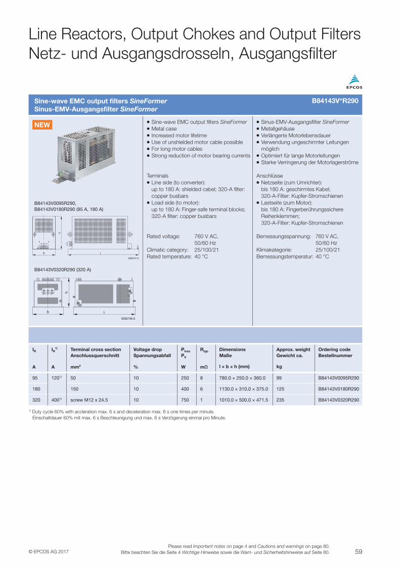
59© EPCOS AG 2017Please read Important notes on page 4 and Cautions and warnings on page 80.
Bitte beachten Sie die Seite 4 Wichtige Hinweise sowie die Warn- und Sicherheitshinweise auf Seite 80.
Line Reactors, Output Chokes and Output FiltersNetz- und Ausgangsdrosseln, Ausgangsfilter
Sine-wave EMC output filters SineFormerSinus-EMV-Ausgangsfilter SineFormer
VV Sine-wave EMC output filters SineFormerVV Metal caseVV Increased motor lifetimeVV Use of unshielded motor cable possibleVV For long motor cables VV Strong reduction of motor bearing currents
TerminalsVV Line side (to converter): up to 180 A: shielded cabel; 320-A filter: copper busbarsVV Load side (to motor): up to 180 A: Finger-safe terminal blocks; 320-A filter: copper busbars
Rated voltage: 760 V AC, 50/60 HzClimatic category: 25/100/21Rated temperature: 40 °C
VV Sinus-EMV-Ausgangsfilter SineFormerVV MetallgehäuseVV Verlängerte MotorlebensdauerVV Verwendung ungeschirmter Leitungen möglichVV Optimiert für lange MotorleitungenVV Starke Verringerung der Motorlagerströme
AnschlüsseVV Netzseite (zum Umrichter): bis 180 A: geschirmtes Kabel; 320-A-Filter: Kupfer-StromschienenVV Lastseite (zum Motor): bis 180 A: Fingerberührungssichere Reihenklemmen; 320-A-Filter: Kupfer-Stromschienen
Bemessungsspannung: 760 V AC, 50/60 HzKlimakategorie: 25/100/21Bemessungstemperatur: 40 °C
B84143V0095R290, B84143V0180R290 (95 A, 180 A)
b
h
SSB2737-8
B84143V0320R290 (320 A)
b
h
SSB2738-G
IR IR1) Terminal cross section
AnschlussquerschnittVoltage dropSpannungsabfall
Ploss
PV
Rtyp DimensionsMaße
Approx. weightGewicht ca.
Ordering codeBestellnummer
A A mm2 % W mΩ l × b × h (mm) kg
95 1201) 50 10 250 8 780.0 × 250.0 × 360.0 99 B84143V0095R290
180 150 10 400 6 1130.0 × 310.0 × 375.0 125 B84143V0180R290
320 4001) screw M12 x 24.5 10 750 1 1010.0 × 500.0 × 471.5 235 B84143V0320R290
1) Duty cycle 60% with accleration max. 6 s and deceleration max. 6 s one times per minute. Einschaltdauer 60% mit max. 6 s Beschleunigung und max. 6 s Verzögerung einmal pro Minute.
B84143V*R290
NEW
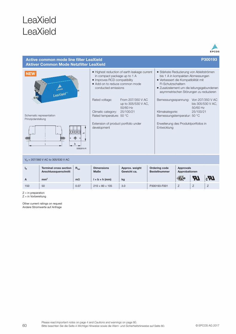
60 © EPCOS AG 2017Please read Important notes on page 4 and Cautions and warnings on page 80.Bitte beachten Sie die Seite 4 Wichtige Hinweise sowie die Warn- und Sicherheitshinweise auf Seite 80.
LeaXieldLeaXield
Active common mode line filter LeaXieldAktiver Common Mode Netzfilter LeaXield
VV Highest reduction of earth leakage current in compact package up to 1 AVV Improves RCD compatibilityVV Add-on to reduce common mode conducted emissions
Rated voltage: From 207/350 V AC up to 305/530 V AC, 50/60 HzClimatic category: 25/100/21Rated temperature: 50 °C
Extension of product portfolio under development
VV Stärkste Reduzierung von Ableitströmen bis 1 A in kompakten AbmessungenVV Verbessert die Kompatibilität mit FI-SchutzschalternVV Zusatzelement um die leitungsgebundenen asymmetrischen Störungen zu reduzieren
Bemessungsspannung: Von 207/350 V AC bis 305/530 V AC, 50/60 HzKlimakategorie: 25/100/21Bemessungstemperatur: 50 °C
Erweiterung des Produktportfolios in Entwicklung
Schematic representationPrinzipdarstellung
SSB2816-R
h
b
VR = 207/360 V AC to 305/530 V AC
IR Terminal cross section Anschlussquerschnitt
Rtyp DimensionsMaße
Approx. weightGewicht ca.
Ordering codeBestellnummer
ApprovalsApprobationen
A mm2 mΩ l × b × h (mm) kg
150 50 0.07 210 × 80 × 105 3.0 P300193-F001 Z Z Z
Z = in preparationZ = in Vorbereitung
Other current ratings on requestAndere Stromwerte auf Anfrage
P300193
NEW
61© EPCOS AG 2017Please read Important notes on page 4 and Cautions and warnings on page 80.
Bitte beachten Sie die Seite 4 Wichtige Hinweise sowie die Warn- und Sicherheitshinweise auf Seite 80.
GeneralAllgemein
Filters for power linesFilter für Netzleitungen
VV Multistage filters with very high attenuation of depending on the type – 100 dB from 150 kHz to 40 GHz or – 100 dB from 14 kHz to 40 GHz
VV RF-tight case made of corrosion-resistant magnetic stainless steelVV Terminal boxes remain 100% RF-tight even with frequent openingVV Attenuation specifications at full load (CISPR 17, MIL-STD-220 A)VV For operating frequencies of 50 Hz, 60 Hz or 400 Hz (with corresponding current and voltage derating)VV Filters also available with 40 or 100 kA EMP protectionVV Supplied complete with all required assembly materials
VV Mehrstufig aufgebaute Filter mit sehr hoher Dämpfung, typabhängig
– 100 dB von 150 kHz bis 40 GHz oder – 100 dB von 14 kHz bis 40 GHz
VV Hochfrequenzdichte Gehäuse aus korrosionsfreiem, magnetischem EdelstahlVV Anschlusskammern sind auch bei mehrmaligem Öffnen noch 100% HF-dichtVV Dämpfungsangaben bei Volllast (CISPR 17, MIL-STD-220 A)VV Für Betriebsfrequenz 50 Hz, 60 Hz oder 400 Hz (bei entsprechendem Strom- und Spannungsderating)VV Filter auch mit EMP-Schutz 40 kA oder 100 kA lieferbarVV Lieferung komplett mit allem erforderlichen Montagematerial
Filters with single chokes – B84299C/D seriesFilter mit Einzeldrosseln – Serie B84299C/D
These universal filters attenuate common and differential-mode interference currents equally well. The high attenuation characteristic remains stable at high leakage currents through the loads (e.g. LISN, V-Network). No coupling between the lines, hence ideal for almost all applications.
Diese Universalfilter mit Einzeldrosseln bedämpfen Gleich- und Gegentakt-Störströme gleichermaßen. Bei hohen Ableitströmen durch die Verbraucher (z.B. Netznachbildung) bleibt die hohe Dämpfungscharakteristik stabil. Keine Verkopplung zwischen den Leitungen, daher für fast alle Anwendungen ideal.
Filters with low leakage current – B84261 and B84263 seriesFilter mit ableitstromarmer Schaltung – Serie B84261 und B84263
Construction with current-compensated chokes that essentially attenuate common-mode interference currents. Thanks to the filter circuit, these series assures a significantly lower leakage current.
Aufbau mit stromkompensierten Drosseln, die im Wesentlichen die Gleichtakt-Störströme bedämpfen. Durch die Filterschaltung ergibt sich bei diesen Reihen ein deutlich niedrigerer Ableitstrom.
Filters for communication, telephone and control linesFilter für Kommunikationsleitungen, Telefon- und Steuerleitungen
VV Multistage filters with very high attenuationVV Stopband attenuation of 100 dB from 10 kHz to 40 GHz depending on the typeVV RF-tight caseVV Also available with integrated EMP protectionVV For a wide range of analog data and ISDN systems
VV Mehrstufig aufgebaute Filter mit sehr hoher DämpfungVV Sperrdämpfung je nach Typ 100 dB ab 10 kHz bis 40 GHzVV Hochfrequenzdichte GehäuseVV Auch mit integriertem EMP-Schutz lieferbarVV Für eine Vielzahl analoger Daten- und ISDN-Systeme
EMP protection unitsEMP-Schutzeinheiten
EMP protection units combine the benefits of gas-filled surge arresters (extremely high discharge capacity) and varistors (high response speed). The arresters are integrated in receptacles and can be tested and replaced as required.
EMP-Schutzeinheiten kombinieren die Vorzüge von edelgasgefüllten Überspannungsableitern (extrem hohes Ableitvermögen) und Varistoren (hohe Ansprechgeschwindigkeit). Die Ableiter sind in Stecksockeln eingebaut und bei Bedarf prüf- und austauschbar.
Filters for Shielded RoomsFilter für geschirmte Räume
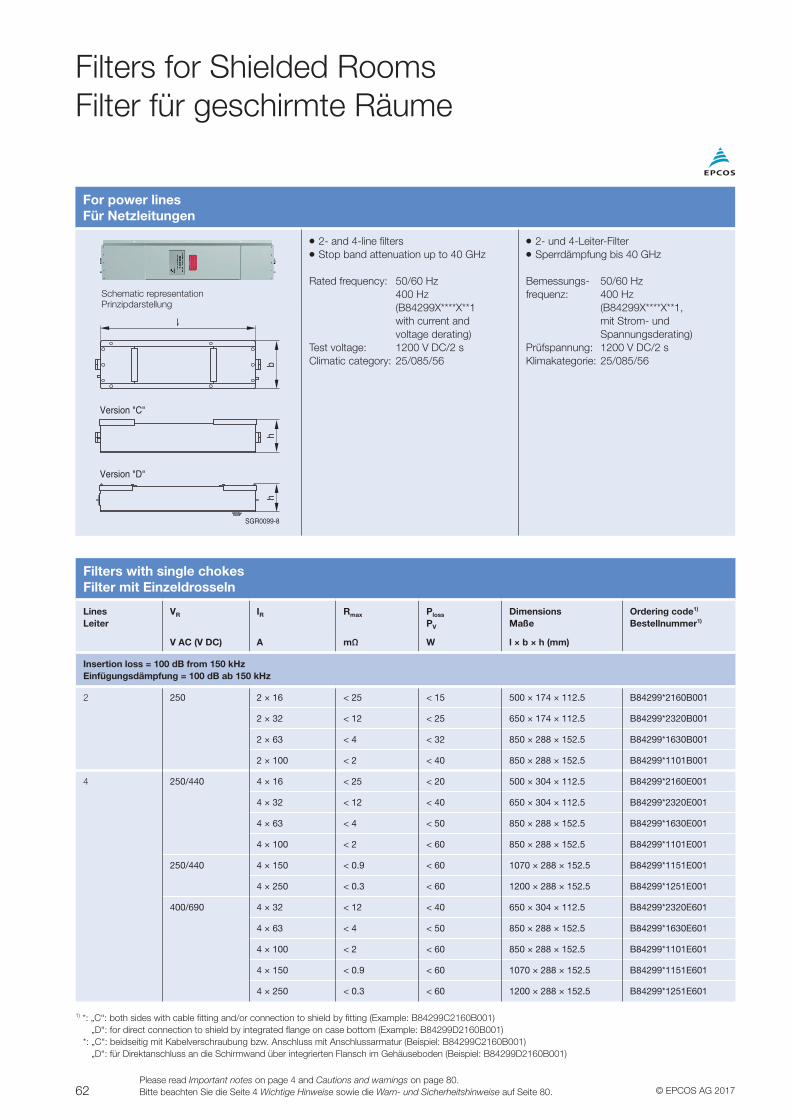
62 © EPCOS AG 2017Please read Important notes on page 4 and Cautions and warnings on page 80.Bitte beachten Sie die Seite 4 Wichtige Hinweise sowie die Warn- und Sicherheitshinweise auf Seite 80.
Filters with single chokesFilter mit Einzeldrosseln
LinesLeiter
VR IR Rmax Ploss
PV
DimensionsMaße
Ordering code1)
Bestellnummer1)
V AC (V DC) A mΩ W l × b × h (mm)
Insertion loss = 100 dB from 150 kHzEinfügungsdämpfung = 100 dB ab 150 kHz
2 250 2 × 16 < 25 < 15 500 × 174 × 112.5 B84299*2160B001
2 × 32 < 12 < 25 650 × 174 × 112.5 B84299*2320B001
2 × 63 < 4 < 32 850 × 288 × 152.5 B84299*1630B001
2 × 100 < 2 < 40 850 × 288 × 152.5 B84299*1101B001
4 250/440 4 × 16 < 25 < 20 500 × 304 × 112.5 B84299*2160E001
4 × 32 < 12 < 40 650 × 304 × 112.5 B84299*2320E001
4 × 63 < 4 < 50 850 × 288 × 152.5 B84299*1630E001
4 × 100 < 2 < 60 850 × 288 × 152.5 B84299*1101E001
250/440 4 × 150 < 0.9 < 60 1070 × 288 × 152.5 B84299*1151E001
4 × 250 < 0.3 < 60 1200 × 288 × 152.5 B84299*1251E001
400/690 4 × 32 < 12 < 40 650 × 304 × 112.5 B84299*2320E601
4 × 63 < 4 < 50 850 × 288 × 152.5 B84299*1630E601
4 × 100 < 2 < 60 850 × 288 × 152.5 B84299*1101E601
4 × 150 < 0.9 < 60 1070 × 288 × 152.5 B84299*1151E601
4 × 250 < 0.3 < 60 1200 × 288 × 152.5 B84299*1251E601
1) *: „C“: both sides with cable fitting and/or connection to shield by fitting (Example: B84299C2160B001) „D“: for direct connection to shield by integrated flange on case bottom (Example: B84299D2160B001) *: „C“: beidseitig mit Kabelverschraubung bzw. Anschluss mit Anschlussarmatur (Beispiel: B84299C2160B001) „D“: für Direktanschluss an die Schirmwand über integrierten Flansch im Gehäuseboden (Beispiel: B84299D2160B001)
Filters for Shielded RoomsFilter für geschirmte Räume
For power linesFür Netzleitungen
VV 2- and 4-line filtersVV Stop band attenuation up to 40 GHz
Rated frequency: 50/60 Hz 400 Hz (B84299X****X**1 with current and voltage derating)Test voltage: 1200 V DC/2 sClimatic category: 25/085/56
VV 2- und 4-Leiter-FilterVV Sperrdämpfung bis 40 GHz
Bemessungs- 50/60 Hzfrequenz: 400 Hz (B84299X****X**1, mit Strom- und Spannungsderating)Prüfspannung: 1200 V DC/2 sKlimakategorie: 25/085/56
SGR0099-8
bh
h
Version "C"
Version "D"
Schematic representationPrinzipdarstellung
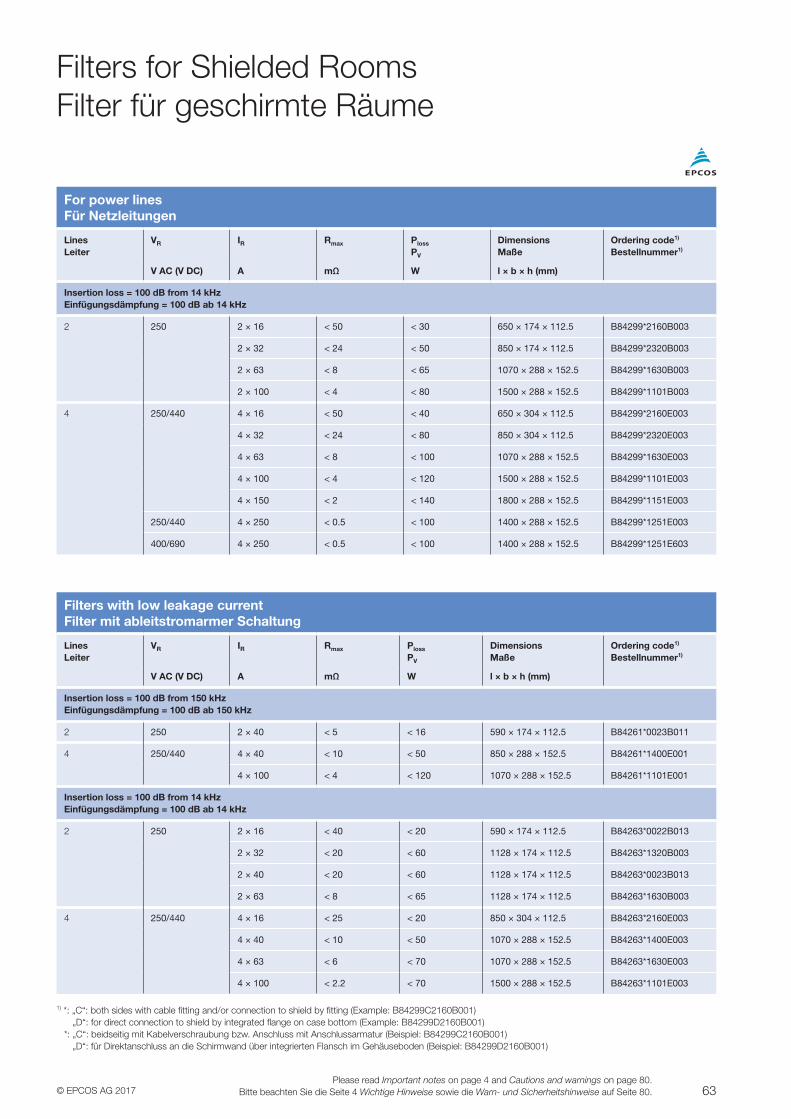
63© EPCOS AG 2017Please read Important notes on page 4 and Cautions and warnings on page 80.
Bitte beachten Sie die Seite 4 Wichtige Hinweise sowie die Warn- und Sicherheitshinweise auf Seite 80.
For power linesFür Netzleitungen
LinesLeiter
VR IR Rmax Ploss
PV
DimensionsMaße
Ordering code1)
Bestellnummer1)
V AC (V DC) A mΩ W l × b × h (mm)
Insertion loss = 100 dB from 14 kHzEinfügungsdämpfung = 100 dB ab 14 kHz
2 250 2 × 16 < 50 < 30 650 × 174 × 112.5 B84299*2160B003
2 × 32 < 24 < 50 850 × 174 × 112.5 B84299*2320B003
2 × 63 < 8 < 65 1070 × 288 × 152.5 B84299*1630B003
2 × 100 < 4 < 80 1500 × 288 × 152.5 B84299*1101B003
4 250/440 4 × 16 < 50 < 40 650 × 304 × 112.5 B84299*2160E003
4 × 32 < 24 < 80 850 × 304 × 112.5 B84299*2320E003
4 × 63 < 8 < 100 1070 × 288 × 152.5 B84299*1630E003
4 × 100 < 4 < 120 1500 × 288 × 152.5 B84299*1101E003
4 × 150 < 2 < 140 1800 × 288 × 152.5 B84299*1151E003
250/440 4 × 250 < 0.5 < 100 1400 × 288 × 152.5 B84299*1251E003
400/690 4 × 250 < 0.5 < 100 1400 × 288 × 152.5 B84299*1251E603
Filters with low leakage currentFilter mit ableitstromarmer Schaltung
LinesLeiter
VR IR Rmax Ploss
PV
DimensionsMaße
Ordering code1)
Bestellnummer1)
V AC (V DC) A mΩ W l × b × h (mm)
Insertion loss = 100 dB from 150 kHzEinfügungsdämpfung = 100 dB ab 150 kHz
2 250 2 × 40 < 5 < 16 590 × 174 × 112.5 B84261*0023B011
4 250/440 4 × 40 < 10 < 50 850 × 288 × 152.5 B84261*1400E001
4 × 100 < 4 < 120 1070 × 288 × 152.5 B84261*1101E001
Insertion loss = 100 dB from 14 kHzEinfügungsdämpfung = 100 dB ab 14 kHz
2 250 2 × 16 < 40 < 20 590 × 174 × 112.5 B84263*0022B013
2 × 32 < 20 < 60 1128 × 174 × 112.5 B84263*1320B003
2 × 40 < 20 < 60 1128 × 174 × 112.5 B84263*0023B013
2 × 63 < 8 < 65 1128 × 174 × 112.5 B84263*1630B003
4 250/440 4 × 16 < 25 < 20 850 × 304 × 112.5 B84263*2160E003
4 × 40 < 10 < 50 1070 × 288 × 152.5 B84263*1400E003
4 × 63 < 6 < 70 1070 × 288 × 152.5 B84263*1630E003
4 × 100 < 2.2 < 70 1500 × 288 × 152.5 B84263*1101E003
1) *: „C“: both sides with cable fitting and/or connection to shield by fitting (Example: B84299C2160B001) „D“: for direct connection to shield by integrated flange on case bottom (Example: B84299D2160B001) *: „C“: beidseitig mit Kabelverschraubung bzw. Anschluss mit Anschlussarmatur (Beispiel: B84299C2160B001) „D“: für Direktanschluss an die Schirmwand über integrierten Flansch im Gehäuseboden (Beispiel: B84299D2160B001)
Filters for Shielded RoomsFilter für geschirmte Räume
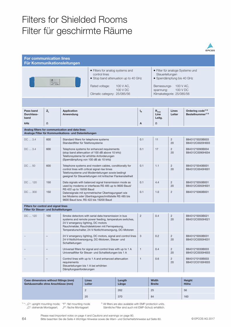
64 © EPCOS AG 2017Please read Important notes on page 4 and Cautions and warnings on page 80.Bitte beachten Sie die Seite 4 Wichtige Hinweise sowie die Warn- und Sicherheitshinweise auf Seite 80.
Case dimensions without fittings (mm)Gehäusemaße ohne Anschlüsse (mm)
LinesLeiter
LengthLänge
WidthBreite
HeightHöhe
2 262 25 56
20 370 84 160
1) *: „C“: upright mounting mode; “F”: flat mounting mode „C“: stehende Montageart; „F“: flache Montageart
2) All filters are also available with EMP protection units. Sämtliche Filter sind auch mit EMP-Schutz erhältlich.
Filters for Shielded RoomsFilter für geschirmte Räume
For communication linesFür Kommunikationsleitungen
VV Filters for analog systems and control linesVV Stop band attenuation up to 40 GHz
Rated voltage: 100 V AC, 100 V DCClimatic category: 25/085/56
VV Filter für analoge Systeme und SteuerleitungenVV Sperrdämpfung bis 40 GHz
Bemessungs- 100 V AC,spannung: 100 V DCKlimakategorie: 25/085/56
Pass bandDurchlass-band
ZL ApplicationAnwendung
IR Rmax
LineLeitg.
LinesLeiter
Ordering code1) 2)
Bestellnummer1) 2)
kHz Ω A Ω
Analog filters for communication and data linesAnaloge Filter für Kommunikations- und Datenleitungen
DC … 3.4 600 Standard filters for telephone systemsStandardfilter für Telefonsysteme
0.1 11 220
B84312*0020B003B84312C0020H003
DC … 3.4 600 Telephone systems for enhanced requirements(stop band attenuation of 100 dB above 10 kHz)Telefonsysteme für erhöhte Anforderungen(Sperrdämpfung von 100 dB ab 10 kHz)
0.1 17 220
B84312*0090B004B84312C0090H004
DC … 50 600 Telephone systems and modem cables, conditionally for control lines with critical signal rise timesTelefonsysteme und Modemleitungen sowie bedingt geeignet für Steuerleitungen mit kritischer Flankensteilheit
0.1 1.1 220
B84312*0040B001B84312C0040H001
DC … 120 150 Data signals with balanced signal transmission mode as used by modems or interfaces RS 485 up to 9600 Baud/ RS 422 up to 19200 BaudDatensignale mit symmetrischer Übertragungsart wie bei Modems oder Übertragungsschnittstelle RS 485 bis 9600 Baud bzw. RS 422 bis 19200 Baud
0.1 4.4 220
B84312*0050B001B84312C0050H001
DC … 300 150 0.1 1.0 2 B84312*0060B001
Filters for control and signal linesFilter für Steuer- und Schaltleitungen
DC … 120 100 Smoke detectors with serial data transmission in bus systems and remote power feeding, temperature switches, 24 V emergency lighting, DC motors Rauchmelder, Rauchdetektoren mit Fernspeisung, Temperaturschalter, 24-V-Notlichtversorgung, DC-Motoren
2 0.4 220
B84312*0050B021B84312C0050H021
– – 24 V emergency lighting, DC motors, signal and control lines24-V-Notlichtversorgung, DC-Motoren, Steuer- und Schaltleitungen
3 0.2 220
B84312*0050B031B84312C0050H031
– – Universal filters for signal and control lines with up to 1 AUniversalfilter für Steuer- und Schaltleitungen bis 1 A
1 0.4 220
B84312*0030B003B84312C0030H003
– – Control lines with up to 1 A and enhanced attenuation requirementsSteuerleitungen bis 1 A bei erhöhten Dämpfungsanforderungen
1 0.6 220
B84312*0100B003B84312C0100H003
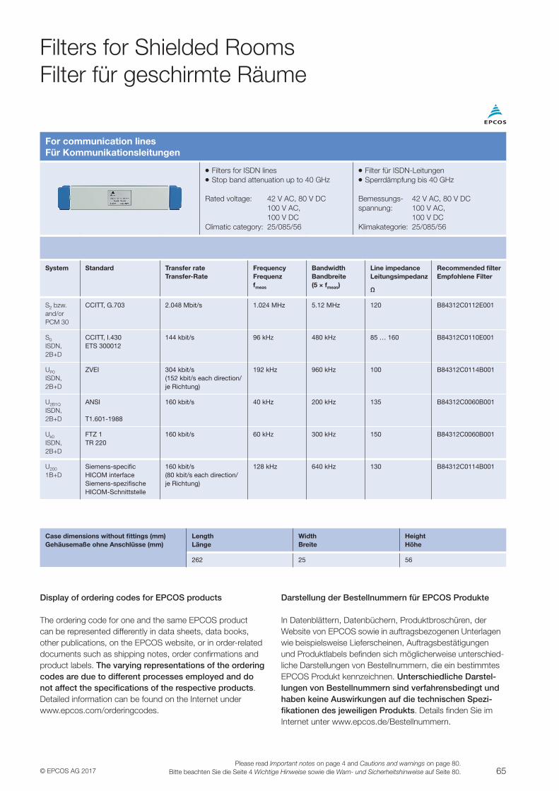
65© EPCOS AG 2017Please read Important notes on page 4 and Cautions and warnings on page 80.
Bitte beachten Sie die Seite 4 Wichtige Hinweise sowie die Warn- und Sicherheitshinweise auf Seite 80.
Filters for Shielded RoomsFilter für geschirmte Räume
For communication linesFür Kommunikationsleitungen
VV Filters for ISDN linesVV Stop band attenuation up to 40 GHz
Rated voltage: 42 V AC, 80 V DC 100 V AC, 100 V DCClimatic category: 25/085/56
VV Filter für ISDN-LeitungenVV Sperrdämpfung bis 40 GHz
Bemessungs- 42 V AC, 80 V DCspannung: 100 V AC, 100 V DCKlimakategorie: 25/085/56
System Standard Transfer rateTransfer-Rate
FrequencyFrequenzfmeas
BandwidthBandbreite(5 × fmeas)
Line impedanceLeitungsimpedanz
Recommended filterEmpfohlene Filter
Ω
S2 bzw.and/orPCM 30
CCITT, G.703 2.048 Mbit/s 1.024 MHz 5.12 MHz 120 B84312C0112E001
S0
ISDN,2B+D
CCITT, I.430ETS 300012
144 kbit/s 96 kHz 480 kHz 85 … 160 B84312C0110E001
UP0
ISDN,2B+D
ZVEI 304 kbit/s(152 kbit/s each direction/je Richtung)
192 kHz 960 kHz 100 B84312C0114B001
U2B1Q
ISDN,2B+D
ANSI
T1.601-1988
160 kbit/s 40 kHz 200 kHz 135 B84312C0060B001
Uk0
ISDN,2B+D
FTZ 1TR 220
160 kbit/s 60 kHz 300 kHz 150 B84312C0060B001
U200
1B+DSiemens-specificHICOM interfaceSiemens-spezifischeHICOM-Schnittstelle
160 kbit/s(80 kbit/s each direction/je Richtung)
128 kHz 640 kHz 130 B84312C0114B001
Case dimensions without fittings (mm)Gehäusemaße ohne Anschlüsse (mm)
LengthLänge
WidthBreite
HeightHöhe
262 25 56
Display of ordering codes for EPCOS products
The ordering code for one and the same EPCOS product can be represented differently in data sheets, data books, other publications, on the EPCOS website, or in order-related documents such as shipping notes, order confirmations and product labels. The varying representations of the ordering codes are due to different processes employed and do not affect the specifications of the respective products. Detailed information can be found on the Internet under www.epcos.com/orderingcodes.
Darstellung der Bestellnummern für EPCOS Produkte
In Datenblättern, Datenbüchern, Produktbroschüren, der Website von EPCOS sowie in auftragsbezogenen Unterlagen wie beispielsweise Lieferscheinen, Auftragsbestätigungen und Produktlabels befinden sich möglicherweise unterschied-liche Darstellungen von Bestellnummern, die ein bestimmtes EPCOS Produkt kennzeichnen. Unterschiedliche Darstel-lungen von Bestellnummern sind verfahrensbedingt und haben keine Auswirkungen auf die technischen Spezi-fikationen des jeweiligen Produkts. Details finden Sie im Internet unter www.epcos.de/Bestellnummern.
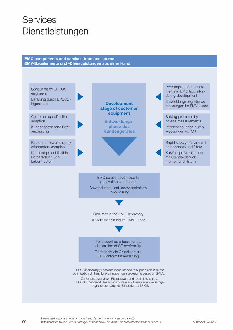
66 © EPCOS AG 2017Please read Important notes on page 4 and Cautions and warnings on page 80.Bitte beachten Sie die Seite 4 Wichtige Hinweise sowie die Warn- und Sicherheitshinweise auf Seite 80.
EMC components and services from one sourceEMV-Bauelemente und -Dienstleistungen aus einer Hand
Consulting by EPCOS engineers
Beratung durch EPCOS-Ingenieure
Precompliance measure-ments in EMC laboratoryduring development
EntwicklungsbegleitendeMessungen im EMV-Labor
Solving problems by on-site measurements
Problemlösungen durchMessungen vor Ort
Customer-speci�c �lter adaption
Kundenspezi�sche Filter-anpassung
Rapid and �exible supply o�aboratory samples
Kurzfristige und �exibleBereitstellung von Labormustern
Rapid supply of standardcomponents and �lters
Kurzfristige Versorgungmit Standardbauele-menten und -�ltern
EMC solution optimized to applications and costs
Anwendungs- und kostenoptimierte EMV-Lösung
Test report as a basis for the declaration of CE conformity
Prüfbericht als Grundlage zur CE-Konformitätserklärung
Final test in the EMC laboratory
Abschlussprüfung im EMV-Labor
EPCOS increasingly uses simulation models to support selection and optimization of �lters. Line simulation during design is based on SPICE.
Zur Unterstützung von Filterauswahl und -optimierung setzt EPCOS zunehmend Simulationsmodelle ein. Basis der entwicklungs-
begleitenden Leitungs-Simulation ist SPICE.
Development stage of customer
equipment
Entwicklungs-phase des
Kundengerätes
ServicesDienstleistungen
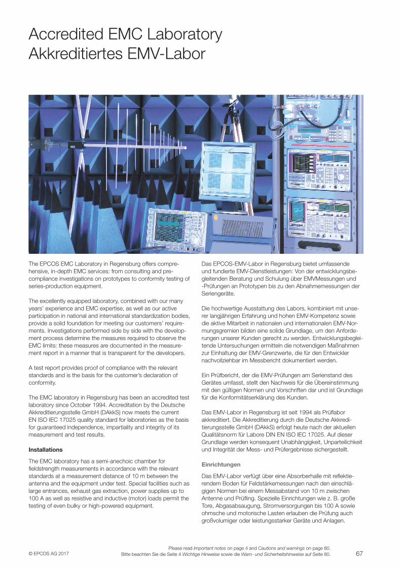
67© EPCOS AG 2017Please read Important notes on page 4 and Cautions and warnings on page 80.
Bitte beachten Sie die Seite 4 Wichtige Hinweise sowie die Warn- und Sicherheitshinweise auf Seite 80.
The EPCOS EMC Laboratory in Regensburg offers compre-hensive, in-depth EMC services: from consulting and pre-compliance investigations on prototypes to conformity testing of series-production equipment.
The excellently equipped laboratory, combined with our many years’ experience and EMC expertise, as well as our active participation in national and international standardization bodies, provide a solid foundation for meeting our customers’ require-ments. Investigations performed side by side with the develop-ment process determine the measures required to observe the EMC limits: these measures are documented in the measure-ment report in a manner that is transparent for the developers.
A test report provides proof of compliance with the relevant standards and is the basis for the customer’s declaration of conformity.
The EMC laboratory in Regensburg has been an accredited test laboratory since October 1994. Accreditation by the Deutsche Akkreditierungsstelle GmbH (DAkkS) now meets the current EN ISO IEC 17025 quality standard for laboratories as the basis for guaranteed independence, impartiality and integrity of its measurement and test results.
Installations
The EMC laboratory has a semi-anechoic chamber forfieldstrength measurements in accordance with the relevant standards at a measurement distance of 10 m between the antenna and the equipment under test. Special facilities such as large entrances, exhaust gas extraction, power supplies up to 100 A as well as resistive and inductive (motor) loads permit the testing of even bulky or high-powered equipment.
Das EPCOS-EMV-Labor in Regensburg bietet umfassende und fundierte EMV-Dienstleistungen: Von der entwicklungsbe-gleitenden Beratung und Schulung über EMVMessungen und -Prüfungen an Prototypen bis zu den Abnahmemessungen der Seriengeräte.
Die hochwertige Ausstattung des Labors, kombiniert mit unse-rer langjährigen Erfahrung und hohen EMV-Kompetenz sowie die aktive Mitarbeit in nationalen und internationalen EMV-Nor-mungsgremien bilden eine solide Grundlage, um den Anforde-rungen unserer Kunden gerecht zu werden. Entwicklungsbeglei-tende Untersuchungen ermitteln die notwendigen Maßnahmen zur Einhaltung der EMV-Grenzwerte, die für den Entwickler nachvollziehbar im Messbericht dokumentiert werden.
Ein Prüfbericht, der die EMV-Prüfungen am Serienstand des Gerätes umfasst, stellt den Nachweis für die Übereinstimmung mit den gültigen Normen und Vorschriften dar und ist Grundlage für die Konformitätserklärung des Kunden.
Das EMV-Labor in Regensburg ist seit 1994 als Prüflabor akkreditiert. Die Akkreditierung durch die Deutsche Akkredi-tierungsstelle GmbH (DAkkS) erfolgt heute nach der aktuellen Qualitätsnorm für Labore DIN EN ISO IEC 17025. Auf dieser Grundlage werden konsequent Unabhängigkeit, Unparteilichkeit und Integrität der Mess- und Prüfergebnisse sichergestellt.
Einrichtungen
Das EMV-Labor verfügt über eine Absorberhalle mit reflektie-rendem Boden für Feldstärkemessungen nach den einschlä-gigen Normen bei einem Messabstand von 10 m zwischen Antenne und Prüfling. Spezielle Einrichtungen wie z. B. große Tore, Abgasabsaugung, Stromversorgungen bis 100 A sowie ohmsche und motorische Lasten erlauben die Prüfung auch großvolumiger oder leistungsstarker Geräte und Anlagen.
Accredited EMC LaboratoryAkkreditiertes EMV-Labor
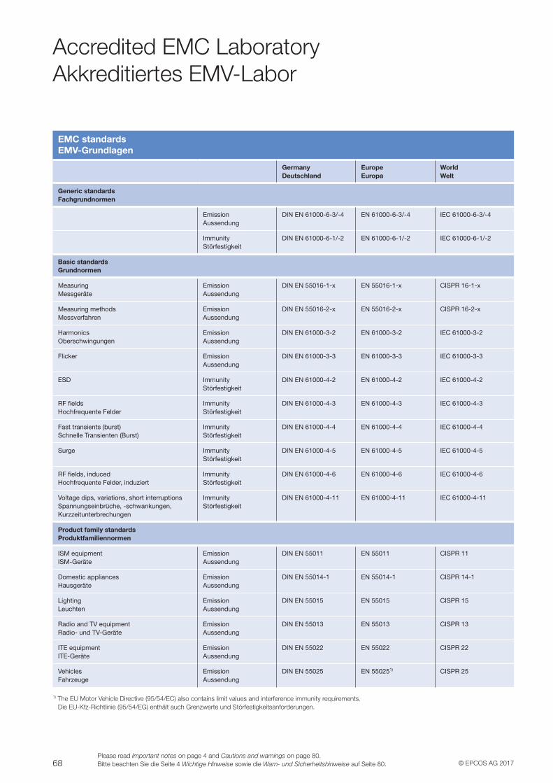
68 © EPCOS AG 2017Please read Important notes on page 4 and Cautions and warnings on page 80.Bitte beachten Sie die Seite 4 Wichtige Hinweise sowie die Warn- und Sicherheitshinweise auf Seite 80.
EMC standardsEMV-Grundlagen
GermanyDeutschland
EuropeEuropa
WorldWelt
Generic standardsFachgrundnormen
Emission Aussendung
DIN EN 61000-6-3/-4 EN 61000-6-3/-4 IEC 61000-6-3/-4
ImmunityStörfestigkeit
DIN EN 61000-6-1/-2 EN 61000-6-1/-2 IEC 61000-6-1/-2
Basic standardsGrundnormen
MeasuringMessgeräte
EmissionAussendung
DIN EN 55016-1-x EN 55016-1-x CISPR 16-1-x
Measuring methodsMessverfahren
EmissionAussendung
DIN EN 55016-2-x EN 55016-2-x CISPR 16-2-x
HarmonicsOberschwingungen
EmissionAussendung
DIN EN 61000-3-2 EN 61000-3-2 IEC 61000-3-2
Flicker EmissionAussendung
DIN EN 61000-3-3 EN 61000-3-3 IEC 61000-3-3
ESD ImmunityStörfestigkeit
DIN EN 61000-4-2 EN 61000-4-2 IEC 61000-4-2
RF fieldsHochfrequente Felder
ImmunityStörfestigkeit
DIN EN 61000-4-3 EN 61000-4-3 IEC 61000-4-3
Fast transients (burst)Schnelle Transienten (Burst)
ImmunityStörfestigkeit
DIN EN 61000-4-4 EN 61000-4-4 IEC 61000-4-4
Surge ImmunityStörfestigkeit
DIN EN 61000-4-5 EN 61000-4-5 IEC 61000-4-5
RF fields, inducedHochfrequente Felder, induziert
ImmunityStörfestigkeit
DIN EN 61000-4-6 EN 61000-4-6 IEC 61000-4-6
Voltage dips, variations, short interruptionsSpannungseinbrüche, -schwankungen,Kurzzeitunterbrechungen
ImmunityStörfestigkeit
DIN EN 61000-4-11 EN 61000-4-11 IEC 61000-4-11
Product family standardsProduktfamiliennormen
ISM equipmentISM-Geräte
EmissionAussendung
DIN EN 55011 EN 55011 CISPR 11
Domestic appliancesHausgeräte
EmissionAussendung
DIN EN 55014-1 EN 55014-1 CISPR 14-1
LightingLeuchten
EmissionAussendung
DIN EN 55015 EN 55015 CISPR 15
Radio and TV equipmentRadio- und TV-Geräte
EmissionAussendung
DIN EN 55013 EN 55013 CISPR 13
ITE equipmentITE-Geräte
EmissionAussendung
DIN EN 55022 EN 55022 CISPR 22
VehiclesFahrzeuge
EmissionAussendung
DIN EN 55025 EN 550251) CISPR 25
1) The EU Motor Vehicle Directive (95/54/EC) also contains limit values and interference immunity requirements. Die EU-Kfz-Richtlinie (95/54/EG) enthält auch Grenzwerte und Störfestigkeitsanforderungen.
Accredited EMC LaboratoryAkkreditiertes EMV-Labor
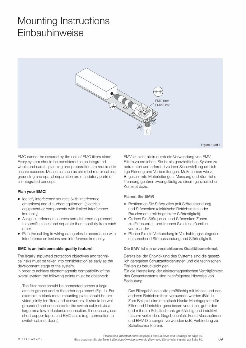
69© EPCOS AG 2017Please read Important notes on page 4 and Cautions and warnings on page 80.
Bitte beachten Sie die Seite 4 Wichtige Hinweise sowie die Warn- und Sicherheitshinweise auf Seite 80.
Filter
Figure / Bild 1
EMC filterEMV-Filter
Mounting InstructionsEinbauhinweise
EMC cannot be assured by the use of EMC filters alone. Every system should be considered as an integrated whole and careful planning and preparation are required to ensure success. Measures such as shielded motor cables, grounding and spatial separation are mandatory parts of an integrated concept.
Plan your EMC!
VV Identify interference sources (with interference emissions) and disturbed equipment (electrical equipment or components with limited interference immunity).VV Assign interference sources and disturbed equipment
to specific zones and separate them spatially from each other.VV Plan the cabling in wiring categories in accordance with
interference emissions and interference immunity.
EMC is an indispensable quality feature!
The legally stipulated protection objectives and techni-cal risks must be taken into consideration as early as the development stage of the system.In order to achieve electromagnetic compatibility of the overall system the following points must be observed:
1. The filter case should be connected across a large area to ground and to the other equipment (Fig. 1). For example, a blank metal mounting plate should be pro-vided jointly for filters and converters. It should be well grounded and connected to the switch cabinet via a large-area low-inductance connection. If necessary, use short copper tapes and EMC seals (e.g. connection to switch cabinet doors).
EMV ist nicht allein durch die Verwendung von EMV-Filtern zu erreichen. Sie ist als ganzheitliches System zu betrachten und erfordert zu ihrer Sicherstellung umsich-tige Planung und Vorbereitungen. Maßnahmen wie z. B. geschirmte Motorleitungen, Massung und räumliche Trennung gehören zwangsläufig zu einem ganzheitlichen Konzept dazu.
Planen Sie EMV!
VV Bestimmen Sie Störquellen (mit Störaussendung) und Störsenken (elektrische Betriebsmittel oder Bauelemente mit begrenzter Störfestigkeit).VV Ordnen Sie Störquellen und Störsenken Zonen
zu (Einbauorte), und trennen Sie diese räumlich voneinander.VV Planen Sie die Verkabelung in Verdrahtungskategorien
entsprechend Störaussendung und Störfestigkeit.
Die EMV ist ein unverzichtbares Qualitätsmerkmal.
Bereits bei der Entwicklung des Systems sind die gesetz-lich geregelten Schutzanforderungen und die technischen Risiken zu berücksichtigen.Für die Herstellung der elektromagnetischen Verträglichkeit des Gesamtsystems sind nachfolgende Hinweise vonBedeutung:
1. Das Filtergehäuse sollte großflächig mit Masse und den anderen Betriebsmitteln verbunden werden (Bild 1). Zum Beispiel eine metallisch blanke Montageplatte für Filter und Umrichter gemeinsam vorsehen, gut erden und mit dem Schaltschrank großflächig und induktivi-tätsarm verbinden. Gegebenenfalls kurze Massebänder und EMV-Dichtungen verwenden (z.B. Verbindung zu Schaltschranktüren).
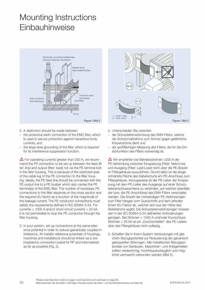
70 © EPCOS AG 2017Please read Important notes on page 4 and Cautions and warnings on page 80.Bitte beachten Sie die Seite 4 Wichtige Hinweise sowie die Warn- und Sicherheitshinweise auf Seite 80.
Mounting InstructionsEinbauhinweise
SSB1828-A
Figure / Bild 2 Figure / Bild 3
L = Length / LängeB = Width / Breite
Electrically conducting braided tape Elektrisch leitendes Flechtband
Welded studsGeschweißte Bolzen
Protective earthSchutzleiterTube connection
Rohrverbindung Grid/Gitter
L < 3
B
2. A distinction should be made between – the protective earth connection of the EMC filter, which
is used to secure protection against hazardous body currents, and
– the large-area grounding of the filter, which is required for its interference suppression function.
V For operating currents greater than 250 A, we recom-mend the PE connection to be set up between the feed (fil-ter: line) and output (filter: load) not via the PE terminal bolt in the filter housing. This is because of the restricted area of the cable lug of the PE connection to the filter hous-ing. Ideally, the PE feed line should be connected with the PE output line to a PE busbar which also carries the PE terminal(s) of the EMC filter. The number of necessary PE connections to the filter depends on the cross section and the required KU factor as a function of the magnitude of the leakage current. The PE conductor connections must satisfy the requirements defined in IEC 60364-5-54. For currents > 1000 A and/or short-circuit currents > 25 kA, it is not permissible to loop the PE conductor through the filter housing.
3. In your system, set up connections at the same refer-ence potential in order to reduce galvanically coupled in-terference. All metallic reference potentials of housings, machines and installations should be linked via a low-impedance connection suited for RF and intermeshed as far as possible (Fig. 2).
2. Unterscheiden Sie zwischen – der Schutzleiterverbindung des EMV-Filters, welche
der Schutzmaßnahme zum Schutz gegen gefährliche Körperströme dient und
– der großflächigen Massung des Filters, die für die Ent-störfunktion des Filters notwendig ist.
V Wir empfehlen bei Betriebsströmen >250 A die PE-Verbindung zwischen Einspeisung (Filter: Netz/Line) und Ausgang (Filter: Last/Load) nicht über die PE-Bolzen im Filtergehäuse auszuführen. Grund dafür ist die einge-schränkte Fläche des Kabelschuhs am PE-Anschluss zum Filtergehäuse. Vorzugsweise ist der PE-Leiter der Einspei-sung mit dem PE-Leiter des Ausgangs auf einer Schutz-leiteranschlussschiene zu verbinden, auf welcher ebenfalls der bzw. die PE-Anschlüsse des EMV-Filters verschaltet werden. Die Anzahl der notwendigen PE-Verbindungen zum Filter hängen vom Querschnitt und dem erforder-lichen KU-Faktor ab, welcher sich aus der Höhe des Ableitstroms ergibt. Die Schutzleiterverbindungen müssen den in der IEC 60364-5-54 definierten Anforderungen genügen. Bei Strömen > 1000 A und/oder Kurzschluss- Strömen > 25 kA ist ein „Durchschleifen“ des PE-Leiters über das Filtergehäuse nicht zulässig.
3. Schaffen Sie in Ihrem System Verbindungen mit glei-chem Bezugspotential zur Reduzierung der galvanisch gekoppelten Störungen. Alle metallischen Bezugspo-tentiale von Gehäusen, Maschinen- und Anlagenteilen sollten niederohmig, hochfrequenztauglich und mög-lichst vermascht verbunden werden (Bild 2).
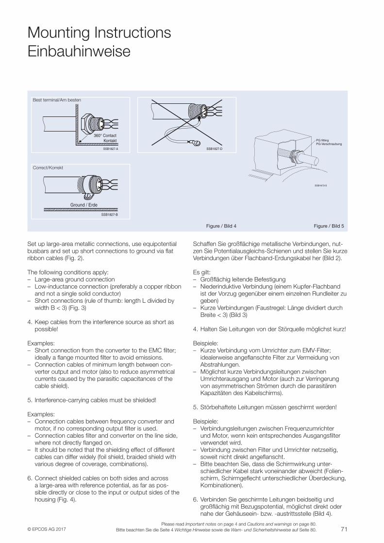
71© EPCOS AG 2017Please read Important notes on page 4 and Cautions and warnings on page 80.
Bitte beachten Sie die Seite 4 Wichtige Hinweise sowie die Warn- und Sicherheitshinweise auf Seite 80.
360° Contact Kontakt
SSB1827-A SSB1827-D
PG fittingPG-Verschraubung
SSB1673-S
SSB1827-B
Ground / Erde
Figure / Bild 4 Figure / Bild 5
Best terminal/Am besten
Correct/Korrekt
Mounting InstructionsEinbauhinweise
Set up large-area metallic connections, use equipotential busbars and set up short connections to ground via flat ribbon cables (Fig. 2).
The following conditions apply: – Large-area ground connection – Low-inductance connection (preferably a copper ribbon
and not a single solid conductor) – Short connections (rule of thumb: length L divided by
width B < 3) (Fig. 3)
4. Keep cables from the interference source as short as possible!
Examples: – Short connection from the converter to the EMC filter;
ideally a flange mounted filter to avoid emissions. – Connection cables of minimum length between con-
verter output and motor (also to reduce asymmetrical currents caused by the parasitic capacitances of the cable shield).
5. Interference-carrying cables must be shielded!
Examples: – Connection cables between frequency converter and
motor, if no corresponding output filter is used. – Connection cables filter and converter on the line side,
where not directly flanged on. – It should be noted that the shielding effect of different
cables can differ widely (foil shield, braided shield with various degree of coverage, combinations).
6. Connect shielded cables on both sides and across a large-area with reference potential, as far as pos-sible directly or close to the input or output sides of the housing (Fig. 4).
Schaffen Sie großflächige metallische Verbindungen, nut-zen Sie Potentialausgleichs-Schienen und stellen Sie kurze Verbindungen über Flachband-Erdungskabel her (Bild 2).
Es gilt: – Großflächig leitende Befestigung – Niederinduktive Verbindung (einem Kupfer-Flachband
ist der Vorzug gegenüber einem einzelnen Rundleiter zu geben)
– Kurze Verbindungen (Faustregel: Länge dividiert durch Breite < 3) (Bild 3)
4. Halten Sie Leitungen von der Störquelle möglichst kurz!
Beispiele: – Kurze Verbindung vom Umrichter zum EMV-Filter;
idealerweise angeflanschte Filter zur Vermeidung von Abstrahlungen.
– Möglichst kurze Verbindungsleitungen zwischen Umrichterausgang und Motor (auch zur Verringerung von asymmetrischen Strömen durch die parasitären Kapazitäten des Kabelschirms).
5. Störbehaftete Leitungen müssen geschirmt werden!
Beispiele: – Verbindungsleitungen zwischen Frequenzumrichter
und Motor, wenn kein entsprechendes Ausgangsfilter verwendet wird.
– Verbindung zwischen Filter und Umrichter netzseitig, soweit nicht direkt angeflanscht.
– Bitte beachten Sie, dass die Schirmwirkung unter-schiedlicher Kabel stark voneinander abweicht (Folien-schirm, Schirmgeflecht unterschiedlicher Überdeckung, Kombinationen).
6. Verbinden Sie geschirmte Leitungen beidseitig und großflächig mit Bezugspotential, möglichst direkt oder nahe der Gehäuseein- bzw. -austrittsstelle (Bild 4).
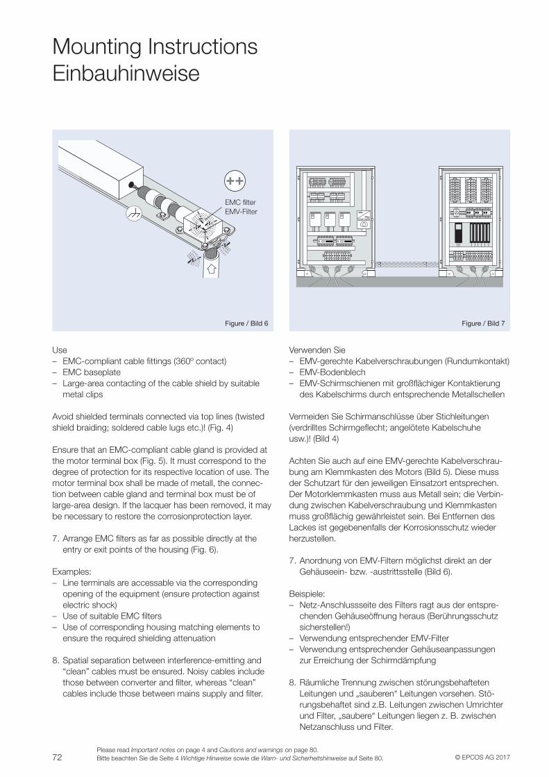
72 © EPCOS AG 2017Please read Important notes on page 4 and Cautions and warnings on page 80.Bitte beachten Sie die Seite 4 Wichtige Hinweise sowie die Warn- und Sicherheitshinweise auf Seite 80.
Mounting InstructionsEinbauhinweise
Filter
Figure / Bild 6 Figure / Bild 7
Use – EMC-compliant cable fittings (360º contact) – EMC baseplate – Large-area contacting of the cable shield by suitable
metal clips
Avoid shielded terminals connected via top lines (twistedshield braiding; soldered cable lugs etc.)! (Fig. 4)
Ensure that an EMC-compliant cable gland is provided at the motor terminal box (Fig. 5). It must correspond to the degree of protection for its respective location of use. The motor terminal box shall be made of metall, the connec-tion between cable gland and terminal box must be of large-area design. If the lacquer has been removed, it may be necessary to restore the corrosionprotection layer.
7. Arrange EMC filters as far as possible directly at the entry or exit points of the housing (Fig. 6).
Examples: – Line terminals are accessable via the corresponding
opening of the equipment (ensure protection against electric shock)
– Use of suitable EMC filters – Use of corresponding housing matching elements to
ensure the required shielding attenuation
8. Spatial separation between interference-emitting and “clean” cables must be ensured. Noisy cables include those between converter and filter, whereas “clean” cables include those between mains supply and filter.
Verwenden Sie – EMV-gerechte Kabelverschraubungen (Rundumkontakt) – EMV-Bodenblech – EMV-Schirmschienen mit großflächiger Kontaktierung
des Kabelschirms durch entsprechende Metallschellen
Vermeiden Sie Schirmanschlüsse über Stichleitungen(verdrilltes Schirmgeflecht; angelötete Kabelschuheusw.)! (Bild 4)
Achten Sie auch auf eine EMV-gerechte Kabelverschrau-bung am Klemmkasten des Motors (Bild 5). Diese muss der Schutzart für den jeweiligen Einsatzort entsprechen. Der Motorklemmkasten muss aus Metall sein; die Verbin-dung zwischen Kabelverschraubung und Klemmkasten muss großflächig gewährleistet sein. Bei Entfernen des Lackes ist gegebenenfalls der Korrosionsschutz wieder herzustellen.
7. Anordnung von EMV-Filtern möglichst direkt an der Gehäuseein- bzw. -austrittsstelle (Bild 6).
Beispiele: – Netz-Anschlussseite des Filters ragt aus der entspre-
chenden Gehäuseöffnung heraus (Berührungsschutz sicherstellen!)
– Verwendung entsprechender EMV-Filter – Verwendung entsprechender Gehäuseanpassungen
zur Erreichung der Schirmdämpfung
8. Räumliche Trennung zwischen störungsbehafteten Leitungen und „sauberen“ Leitungen vorsehen. Stö-rungsbehaftet sind z.B. Leitungen zwischen Umrichter und Filter, „saubere“ Leitungen liegen z. B. zwischen Netzanschluss und Filter.
EMC filterEMV-Filter
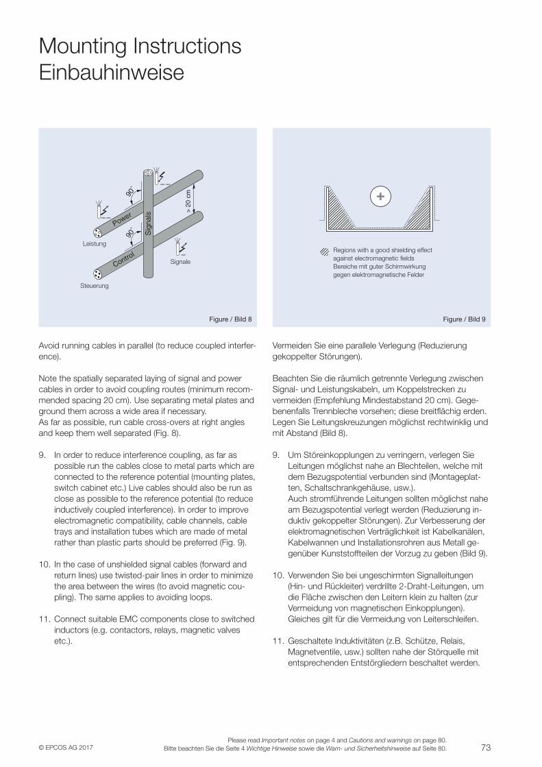
73© EPCOS AG 2017Please read Important notes on page 4 and Cautions and warnings on page 80.
Bitte beachten Sie die Seite 4 Wichtige Hinweise sowie die Warn- und Sicherheitshinweise auf Seite 80.
Mounting InstructionsEinbauhinweise
Figure / Bild 8 Figure / Bild 9
Avoid running cables in parallel (to reduce coupled interfer-ence).
Note the spatially separated laying of signal and power cables in order to avoid coupling routes (minimum recom-mended spacing 20 cm). Use separating metal plates and ground them across a wide area if necessary.As far as possible, run cable cross-overs at right angles and keep them well separated (Fig. 8).
9. In order to reduce interference coupling, as far as possible run the cables close to metal parts which are connected to the reference potential (mounting plates, switch cabinet etc.) Live cables should also be run as close as possible to the reference potential (to reduce inductively coupled interference). In order to improve electromagnetic compatibility, cable channels, cable trays and installation tubes which are made of metal rather than plastic parts should be preferred (Fig. 9).
10. In the case of unshielded signal cables (forward and return lines) use twisted-pair lines in order to minimize the area between the wires (to avoid magnetic cou-pling). The same applies to avoiding loops.
11. Connect suitable EMC components close to switched inductors (e.g. contactors, relays, magnetic valves etc.).
Vermeiden Sie eine parallele Verlegung (Reduzierung gekoppelter Störungen).
Beachten Sie die räumlich getrennte Verlegung zwischen Signal- und Leistungskabeln, um Koppelstrecken zu vermeiden (Empfehlung Mindestabstand 20 cm). Gege-benenfalls Trennbleche vorsehen; diese breitflächig erden. Legen Sie Leitungskreuzungen möglichst rechtwinklig und mit Abstand (Bild 8).
9. Um Störeinkopplungen zu verringern, verlegen Sie Leitungen möglichst nahe an Blechteilen, welche mit dem Bezugspotential verbunden sind (Montageplat-ten, Schaltschrankgehäuse, usw.). Auch stromführende Leitungen sollten möglichst nahe am Bezugspotential verlegt werden (Reduzierung in-duktiv gekoppelter Störungen). Zur Verbesserung der elektromagnetischen Verträglichkeit ist Kabelkanälen, Kabelwannen und Installationsrohren aus Metall ge-genüber Kunststoffteilen der Vorzug zu geben (Bild 9).
10. Verwenden Sie bei ungeschirmten Signalleitungen (Hin- und Rückleiter) verdrillte 2-Draht-Leitungen, um die Fläche zwischen den Leitern klein zu halten (zur Vermeidung von magnetischen Einkopplungen). Gleiches gilt für die Vermeidung von Leiterschleifen.
11. Geschaltete Induktivitäten (z.B. Schütze, Relais, Magnetventile, usw.) sollten nahe der Störquelle mit entsprechenden Entstörgliedern beschaltet werden.
Steuerung
Leistung
Signale
Regions with a good shielding effectagainst electromagnetic fieldsBereiche mit guter Schirmwirkunggegen elektromagnetische Felder
74 © EPCOS AG 2017Please read Important notes on page 4 and Cautions and warnings on page 80.Bitte beachten Sie die Seite 4 Wichtige Hinweise sowie die Warn- und Sicherheitshinweise auf Seite 80.
Mounting InstructionsEinbauhinweise
12. For control signals in the vicinity of high interference levels, use transmission techniques such as:
– Differential-mode transmission systems with twisted-pair lines in conjunction with data line chokes (see also our data book “Chokes and Inductors”).
– Transmission of digital signals acc. to the RS-422 standard or in extreme cases crossing the interference region with fiber-optic cables.
13. Note the mounting position of the filters! The as-sembly must always take care not to impair natural convection. This includes the use of ventilation slits in the filter housing and sufficient spacing to the other components. Over-head mounting is never permis-sible. In the event of unusual mounting situations, the thermal conditions shall be checked after coordination with EPCOS.
14. Noise minimization A choke made of highly diverse core materials repre-sents a significant frequency-dependent filter com-ponent. Electro-acoustic effects must inevitably be expected in AC applications. The materials and pro-cessing used generate (for industrial sector) suitable noise levels by operation in networks with harmon-ics complying to EN 50160. However, these can rise significantly in the event of higher harmonic compo-nents. For sensitive applications such as office installa-tion, therefore, customers should contact EPCOS for advice.
15. Length of motor cables and motor types used (Fig. 10). For converter applications, output voltages are generated that typically have almost rectangular waveforms. These are essentially characterized by the rise rate expressed as the dv/dt value and the switch-ing frequency of the converter. The cables and motors present in the output network of the converter with their inductive and capacitive components significantly determine the EMC properties of the system. Thus resonances of the cable/motor combination are often reflected in the resonance of the interference voltage measurement at the converter input.
12. Verwenden Sie für Steuersignale in der Umgebung hoher Störpegel entsprechende Schaltungstechnik, z. B.:
– Symmetrische Übertragungssysteme mit verdrillten Leitungspaaren in Verbindung mit Datenleitungsdros-seln (siehe auch unser Datenbuch „Drosseln und Induktivitäten“),
– Übertragung von Digitalsignalen entspr. RS-422- Standard oder in extremen Fällen Durchqueren des Störbereiches mittels Lichtleiter.
13. Beachten Sie die Einbaulage der Filter! Die Montage muss grundsätzlich so erfolgen, dass die natürliche Konvektion nicht beeinträchtigt wird. Dazu gehört die Berücksichtigung von Lüftungsschlitzen im Filtergehäuse und der ausreichende Abstand zu an-deren Einbauten. Überkopfmontage ist grundsätzlich ausgeschlossen. Bei besonderen Einbausituationen ist in Rücksprache mit EPCOS eine Prüfung der thermi-schen Bedingungen erforderlich.
14. Geräuschminimierung Ein wesentliches frequenzabhängiges Filterbauelement ist die Drossel mit sehr unterschiedlichen Kernmateria-lien. In Wechselspannungsapplikationen ist zwangsläu-fig mit elektroakustischen Effekten zu rechnen. Die ein-gesetzten Materialien und Verarbeitungstechnologien erzeugen bei Einhaltung der Oberschwingungsanteile entsprechend der Norm EN 50160 für den Einsatz im Industriebereich angemessene Geräuschpegel. Diese können jedoch bei höheren Oberschwingungsanteilen deutlich ansteigen. Bei sensiblen Applikationen, wie der Montage im Büro, sollte die Beratung von EPCOS in Anspruch genommen werden.
15. Motorleitungen und Motortypen (Bild 10). Bei Umrichterapplikationen werden Ausgangsspan-nungen erzeugt, welche nahezu rechteckige Kurven-formen besitzen. Diese werden im Wesentlichen durch die Anstiegsgeschwindigkeit als du/dt-Wert und die Schaltfrequenz des Umrichters charakterisiert. Die im Ausgangsnetzwerk des Umrichters liegenden Kabel und Motoren mit ihren induktiven und kapazitiven Komponenten bestimmen die EMV-Eigenschaften des Systems wesentlich. So sind Resonanzen der Kombination von Kabel und Motor in vielen Fällen als Resonanz der Störspannungsmessung am Umrichter-eingang wiederzufinden.
V
V
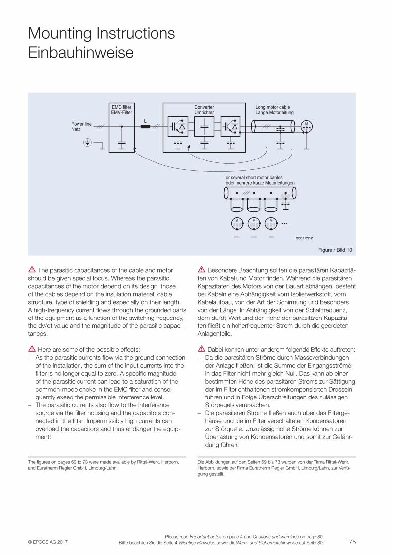
75© EPCOS AG 2017Please read Important notes on page 4 and Cautions and warnings on page 80.
Bitte beachten Sie die Seite 4 Wichtige Hinweise sowie die Warn- und Sicherheitshinweise auf Seite 80.
Mounting InstructionsEinbauhinweise
SSB2177-Z
L
Converter
Power line
EMC filter
M
Long motor cable
or several short motor cables
M
MM
Netz
Umrichter Lange Motorleitung
oder mehrere kurze Motorleitungen
EMV-Filter
Figure / Bild 10
V The parasitic capacitances of the cable and motor should be given special focus. Whereas the parasitic capacitances of the motor depend on its design, those of the cables depend on the insulation material, cable structure, type of shielding and especially on their length. A high-frequency current flows through the grounded parts of the equipment as a function of the switching frequency, the dv/dt value and the magnitude of the parasitic capaci-tances.
V Here are some of the possible effects: – As the parasitic currents flow via the ground connection
of the installation, the sum of the input currents into the filter is no longer equal to zero. A specific magnitude of the parasitic current can lead to a saturation of the common-mode choke in the EMC filter and conse-quently exeed the permissible interference level.
– The parasitic currents also flow to the interference source via the filter housing and the capacitors con-nected in the filter! Impermissibly high currents can overload the capacitors and thus endanger the equip-ment!
The figures on pages 69 to 73 were made available by Rittal-Werk, Herborn, and Euratherm Regler GmbH, Limburg/Lahn.
V Besondere Beachtung sollten die parasitären Kapazitä-ten von Kabel und Motor finden. Während die parasitären Kapazitäten des Motors von der Bauart abhängen, besteht bei Kabeln eine Abhängigkeit vom Isolierwerkstoff, vom Kabelaufbau, von der Art der Schirmung und besonders von der Länge. In Abhängigkeit von der Schaltfrequenz, dem du/dt-Wert und der Höhe der parasitären Kapazitä-ten fließt ein höherfrequenter Strom durch die geerdeten Anlagenteile.
V Dabei können unter anderem folgende Effekte auftreten: – Da die parasitären Ströme durch Masseverbindungen
der Anlage fließen, ist die Summe der Eingangsströme in das Filter nicht mehr gleich Null. Das kann ab einer bestimmten Höhe des parasitären Stroms zur Sättigung der im Filter enthaltenen stromkompensierten Drosseln führen und in Folge Überschreitungen des zulässigen Störpegels verursachen.
– Die parasitären Ströme fließen auch über das Filterge-häuse und die im Filter verschalteten Kondensatoren zur Störquelle. Unzulässig hohe Ströme können zur Überlastung von Kondensatoren und somit zur Gefähr-dung führen!
Die Abbildungen auf den Seiten 69 bis 73 wurden von der Firma Rittal-Werk, Herborn, sowie der Firma Euratherm Regler GmbH, Limburg/Lahn, zur Verfü-gung gestellt.
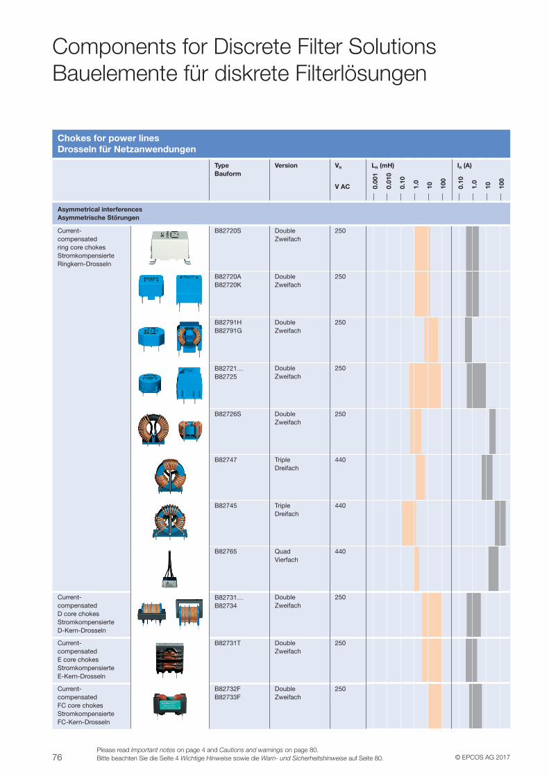
76 © EPCOS AG 2017Please read Important notes on page 4 and Cautions and warnings on page 80.Bitte beachten Sie die Seite 4 Wichtige Hinweise sowie die Warn- und Sicherheitshinweise auf Seite 80.
Components for Discrete Filter SolutionsBauelemente für diskrete Filterlösungen
Chokes for power linesDrosseln für Netzanwendungen
TypeBauform
Version VR
V AC
LR (mH) IR (A)
Asymmetrical interferencesAsymmetrische Störungen
Current- compensated ring core chokesStromkompensierte Ringkern-Drosseln
B82720S DoubleZweifach
250
B82720AB82720K
DoubleZweifach
250
B82791HB82791G
DoubleZweifach
250
B82721…B82725
DoubleZweifach
250
B82726S DoubleZweifach
250
B82747 TripleDreifach
440
B82745 TripleDreifach
440
B82765 QuadVierfach
440
Current- compensated D core chokesStromkompensierte D-Kern-Drosseln
B82731…B82734
DoubleZweifach
250
Current- compensated E core chokesStromkompensierte E-Kern-Drosseln
B82731T DoubleZweifach
250
Current- compensated FC core chokesStromkompensierte FC-Kern-Drosseln
B82732FB82733F
DoubleZweifach
250
0.00
1
0.01
0
0.10
1.0
10 100
0.10
1.0
10 100
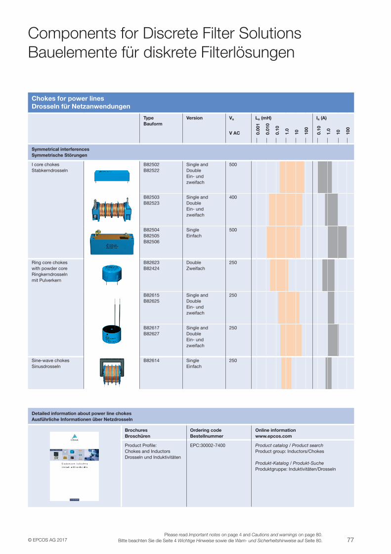
77© EPCOS AG 2017Please read Important notes on page 4 and Cautions and warnings on page 80.
Bitte beachten Sie die Seite 4 Wichtige Hinweise sowie die Warn- und Sicherheitshinweise auf Seite 80.
Components for Discrete Filter SolutionsBauelemente für diskrete Filterlösungen
Chokes for power linesDrosseln für Netzanwendungen
TypeBauform
Version VR
V AC
LR (mH) IR (A)
Symmetrical interferencesSymmetrische Störungen
I core chokesStabkerndrosseln
B82502B82522
Single and DoubleEin- und zweifach
500
B82503B82523
Single and DoubleEin- und zweifach
400
B82504B82505B82506
SingleEinfach
500
Ring core chokes with powder coreRingkerndrosseln mit Pulverkern
B82623B82424
DoubleZweifach
250
B82615B82625
Single and DoubleEin- und zweifach
250
B82617B82627
Single and DoubleEin- und zweifach
250
Sine-wave chokesSinusdrosseln
B82614 SingleEinfach
250
0.00
1
0.01
0
0.10
1.0
10 100
0.10
1.0
10 100
Detailed information about power line chokesAusführliche Informationen über Netzdrosseln
BrochuresBroschüren
Ordering codeBestellnummer
Online informationwww.epcos.com
Product Profile:Chokes and InductorsDrosseln und Induktivitäten
EPC:30002-7400 Product catalog / Product searchProduct group: Inductors/Chokes
Produkt-Katalog / Produkt-SucheProduktgruppe: Induktivitäten/Drosseln
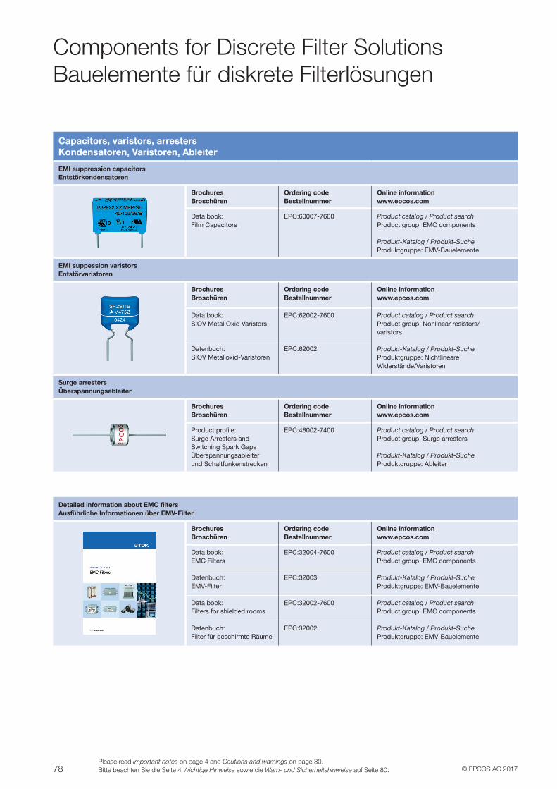
78 © EPCOS AG 2017Please read Important notes on page 4 and Cautions and warnings on page 80.Bitte beachten Sie die Seite 4 Wichtige Hinweise sowie die Warn- und Sicherheitshinweise auf Seite 80.
Components for Discrete Filter SolutionsBauelemente für diskrete Filterlösungen
Detailed information about EMC filtersAusführliche Informationen über EMV-Filter
BrochuresBroschüren
Ordering codeBestellnummer
Online informationwww.epcos.com
Data book:EMC Filters
EPC:32004-7600 Product catalog / Product searchProduct group: EMC components
Produkt-Katalog / Produkt-SucheProduktgruppe: EMV-Bauelemente
Datenbuch:EMV-Filter
EPC:32003
Data book:Filters for shielded rooms
EPC:32002-7600 Product catalog / Product searchProduct group: EMC components
Produkt-Katalog / Produkt-SucheProduktgruppe: EMV-Bauelemente
Datenbuch:Filter für geschirmte Räume
EPC:32002
Capacitors, varistors, arrestersKondensatoren, Varistoren, Ableiter
EMI suppression capacitorsEntstörkondensatoren
BrochuresBroschüren
Ordering codeBestellnummer
Online informationwww.epcos.com
Data book:Film Capacitors
EPC:60007-7600 Product catalog / Product searchProduct group: EMC components
Produkt-Katalog / Produkt-SucheProduktgruppe: EMV-Bauelemente
EMI suppession varistorsEntstörvaristoren
BrochuresBroschüren
Ordering codeBestellnummer
Online informationwww.epcos.com
Data book:SIOV Metal Oxid Varistors
EPC:62002-7600 Product catalog / Product searchProduct group: Nonlinear resistors/ varistors
Produkt-Katalog / Produkt-SucheProduktgruppe: Nichtlineare Widerstände/Varistoren
Datenbuch:SIOV Metalloxid-Varistoren
EPC:62002
Surge arrestersÜberspannungsableiter
BrochuresBroschüren
Ordering codeBestellnummer
Online informationwww.epcos.com
Product profile:Surge Arresters andSwitching Spark GapsÜberspannungsableiterund Schaltfunkenstrecken
EPC:48002-7400 Product catalog / Product searchProduct group: Surge arresters
Produkt-Katalog / Produkt-SucheProduktgruppe: Ableiter
79© EPCOS AG 2017Please read Important notes on page 4 and Cautions and warnings on page 80.
Bitte beachten Sie die Seite 4 Wichtige Hinweise sowie die Warn- und Sicherheitshinweise auf Seite 80.
Environmental ProtectionUmweltschutz
Global environmental management
With our global environmental management in accordance with ISO 14001 we are protecting the environment to the same high standard in all parts of the world. The same requirements are placed on every EPCOS site; external insti-tutes ensure, at regular intervals, that they are being observed.As well as satisfying both statutory requirements and those imposed by the relevant authorities, our environmental man-agement system aims to utilize natural resources efficiently. For that reason, we use our technological expertise to design and manufacture our passive electronic components in the most environmentally compatible way possible. We are contin-uously optimizing our products and processes in order to use materials in a way that minimizes the impact on resources, to use substitutes for hazardous materials wherever possible, and to reduce waste to a minimum.An obligatory list of materials and substances (the “EPCOS BAD-SL”) has its foundations in our environmental manage-ment system, and this guarantees that a consistent procedure is applied to all EPCOS products. We are, moreover, active on a large number of committees, working groups and commis-sions associated with the electronics industry, with the aim of pushing forward the standardization of material data sheets for passive electronic components. The materials contained in our products are listed in detail on this material data sheets (the so-called “Umbrella Specifications”), so that customers, in turn, can satisfy the environmental conditions imposed upon them.
RoHS
The term “RoHS-compatible” shall mean the following: Components defined as “RoHS-compatible” are compat-ible with the requirements of Art. 4 of Directive 2011/65/EU (“RoHS II”) of the European Parliament and of the Council on the restriction of the use of certain hazardous substances in electrical and electronic equipment of 8 June 2011 and with the requirements of the provisions which will result from transposition of RoHS II into national law to the extent such provisions reflect the directive.“RoHS-compatible” components do not contain any of the following substances at a content exceeding the maximum concentration limits of 0.1% for lead, mercury, hexavalent chromium, PBB, PBDE, DEHP, BBP, DBP, DIPB and 0.01% for cadmium at a homogeneous material level, except the application is exempted by Annex III of “RoHS II”.
Globales Umweltmanagement
Mit unserem globalen Umweltmanagement nach ISO 14001 sorgen wir für Umweltschutz auf weltweit gleich hohem Niveau. Für alle EPCOS-Standorte gelten dieselben Anfor-derungen, deren Einhaltung in regelmäßigen Abständen von externen Instituten geprüft wird.Neben dem Erfüllen behördlicher und gesetzlicher Aufla-gen ist es das Ziel unseres Umweltmanagements, natürli-che Ressourcen effizient einzusetzen. Dazu gestalten wir auf der Grundlage unserer Technologiekompetenz unsere passiven elektronischen Bauelemente und deren Herstel-lung so umweltverträglich wie möglich. Unsere Produkte und Prozesse optimieren wir kontinuierlich hinsichtlich eines Ressourcen schonenden Materialeinsatzes, substituieren Gefahrenstoffe nach Möglichkeit und reduzieren Abfälle auf ein Minimum.In unserem Umweltmanagement-System ist eine verbindliche Material- und Substanzliste (die „EPCOS BAD-SL“) verankert, die für EPCOS-Produkte ein einheitliches Vorgehen garantiert. Darüber hinaus sind wir in zahlreichen Gremien, Arbeitsgrup-pen und Kommissionen der Elektronikindustrie tätig, um die Standardisierung von Materialdatenblättern passiver elektro-nischer Bauelemente voranzutreiben. Die Inhaltsstoffe unserer Produkte sind in solchen Materialdatenblättern (den sog. „Umbrella Specifications“) detailliert aufgeführt, damit Kun-den wiederum die an sie gestellten Umweltauflagen erfüllen können.
RoHS
Der Begriff „RoHS-kompatibel“ bedeutet Folgendes: Als „RoHS-kompatibel“ definierte Komponenten sind verein-bar mit den Anforderungen von Art. 4 der Richtlinie 2011/65/EU („RoHS II“) des Europäischen Parlaments und des Rates zur Beschränkung bestimmter gefährlicher Stoffe in Elektro- und Elektronikgeräten vom 8. Juni 2011 und mit den Anforderungen von Bestimmungen, die sich aus der Umset-zung von RoHS II in nationales Recht ergeben, soweit sie die Richtlinie widerspiegeln.„RoHS-kompatible“ Komponenten enthalten keine der lt. ROHS Art 4 verbotenen Stoffe in einer Konzentration, welche die derzeit vorgegebenen Höchstwerte in den homogenen Materialien (0,1% für Blei, Quecksilber, sechswertiges Chrom, PBB, PBDE, DEHP, BBP, DBP, DIPB und 0,01% für Cadmium) überschreiten, es sei denn, die Anwendung ist in Anhang III von „RoHS II“ ausgenommen.
80 © EPCOS AG 2017Please read Important notes on page 4 and Cautions and warnings on page 80.Bitte beachten Sie die Seite 4 Wichtige Hinweise sowie die Warn- und Sicherheitshinweise auf Seite 80.
Cautions and WarningsWarn- und Sicherheitshinweise
z Please note the advices in our data book “EMC Filters” (latest edition); attention should be paid to the chapter “General safety notes”. z Please read all safety and warning notes carefully before installing the EMC filter and putting it into operation. The same applies to the warning signs on the filter. Please ensure that the signs are not removed nor their legibility impaired by external influences. z It shall be ensured that only qualified persons (electricity specialists) are engaged on work such as planning, assembly, installation, operation, repair and maintenance. They must be provided with the corresponding documentation. zDanger of electric shock. filters contain components that store an electric charge. Dangerous voltages can continue to exist at the filter terminals for longer than five minutes even after the power has been switched off. z The protective earth connections shall be the first to be made when the filter is installed and the last to be disconnected. Depending on the magnitude of the leakage currents, the particular specifications for making the protective−earth connection must be observed. z Impermissible overloading of the filter, such as with circuits able to cause resonances, impermissible voltages at higher frequencies etc. can lead to bodily injury and death as well as cause substantial material damages (e.g. destruction of the filter housing). z Filters must be protected in the application against impermissible exceeding of the rated currents by overcurrent protective devices. z In case of leakage currents > 3.5 mA you shall mount the PE conductor stationary with the required cross section before beginning of operation and save it against disconnecting. For leakage currents Ileak
1) ≤10 mA the PE conductor must have a KU value 2) of 4.5; for leakage currents Ileak > 10 mA the PE conductor must have a KU value of 6. zOutput chokes and output filters must be protected in the application against impermissible exceeding of the component temperature. z The converter output frequency must be within the specified range to avoid resonances and uncontrolled warming of the output chokes and output filters. zBecause the product can become very hot during operation, there is the risk of burns if touched. The product can remain hot for some time after the power is switched off!
VV Bitte beachten Sie auch die Hinweise in unserem Datenbuch „EMV-Filter“ (aktuelle Ausgabe); besonders das Kapitel „Generelle Sicherheitshinweise“.VV Bitte lesen Sie vor der Installation und Inbetriebnahme des EMV-Filters alle Sicherheits- und Warnhinweise sorgfältig durch. Dieses gilt auch für die am Filter angebrachten Warnschilder. Bitte achten Sie darauf, dass die Schilder nicht entfernt werden oder die Lesbarkeit durch äußere Einflüsse beeinträchtigt wird. VV Es ist zu gewährleisten, dass nur qualifizierte Personen (entsprechend Definition Elektrofachkräfte) mit den Arbeiten Planung, Montage, Installation, Inbetriebnahme, Reparatur und Wartung beauftragt werden. Diesen Personen sind die entsprechenden Unterlagen zur Verfügung zu stellen.VV Gefährdung durch elektrischen Schlag: Filter enthalten ladungsspeichernde Bauelemente. An den Filteranschlüssen können auch nach Abschalten der Netzspannung länger als 5 Minuten gefährliche Spannungen anliegen.VV Bei der Installation des Filters sind grundsätzlich die Schutzleiterverbindungen als erstes anzuschließen. Bei der Deinstallation sind sie als letztes zu entfernen. In Abhängigkeit der Höhe der Ableitströme sind die besonderen Vorschriften für die Ausführung der Schutzleiterverbindung zu beachten.VV Unzulässige Überlastung der Filter, wie z. B. durch resonanzfähige Kreise und unzulässige höherfrequente Spannungsbelastungen, können zu schweren Körperverletzungen und Tod sowie erheblichen Sachschäden führen (z. B. durch Bersten des Filtergehäuses).VV Filter sind in der Applikation durch geeignete Überstromschutzeinrichtungen gegen unzulässige Überschreitung der Bemessungströme zu schützen.VV Im Fall von Ableitströmen > 3,5 mA muß vor der Inbetriebnahme der Schutzleiter mit dem vorgeschriebenen Leiterquerschnitt angeschlossen und gegen Lockern gesichert werden! Mindestforderung für den Schutzleiter KU-Wert 2) = 4,5 für Ableitströme IAbl
1) ≤10 mA bzw. KU = 6 für IAbl > 10 mA.VV Ausgangsdrossel und –filter müssen in der Applikation gegen unerlaubte Überschreitung der Komponententemperatur geschützt werden.VV Die Ausgangsfrequenz des Umrichters muss innerhalb des spezifizierten Bereichs liegen, um Resonanzen und unkontrollierte Erwärmung der Ausgangsdrossel und –filter zu vermeiden.VV Bauteil kann sich während des Betriebszustandes stark erhitzen. Deshalb wird auf eine Verbrennungsgefahr hingewiesen. Diese kann auch nach Abschalten des Betriebszustandes einige Zeit weiter bestehen.
1) Ileak = Leakage current let−go2) The KU value (symbol KU) is a classification parameter of safety−referred failure types designed to ensure protection against hazardous body currents and excessive heating. (DIN VDE 0800-1, 0800-8, 0800-9) A value of KU = 4.5 with respect to interruptions is attained: − with a permanently connected protective earth connections ≥ 1.5 mm2
− with a protective earth connection ≥ 2.5 mm2 via connectors for industrial equipment (IEC 60309−2). KU = 6 with respect to interruptions is achieved for fixed-connection lines ≥ 10 mm2, where the type of connection and installation is conform to the specification for PEN conductors according to DIN VDE 0100-540.
1) IAbl = Ableitstrom- let−go2) Der KU-Wert ist eine Klassifizierungsgröße von sicherheitsbezogenen Ausfallarten zum Schutz gegen gefährliche Körperströme und zu hohe Erwärmung. (DIN VDE 0800-1, 0800-8, 0800-9) Ein Wert von KU = 4,5 in Bezug auf Unterbrechung wird erreicht: − bei fest angeschlossener Schutzleiterverbindung ≥ 1,5 mm2
− bei einer Schutzleiterverbindung ≥ 2,5 mm2 über Steckverbinder für industrielle Anlagen (IEC 60309-2). KU = 6 in Bezug auf Unterbrechung wird erreicht bei fest angeschlossenen Leitern ≥ 10 mm2, wobei Anschlußart und Verlegung den Anforderungen für PEN-Leitern nach gültigen Normen entsprechen (DIN VDE 0100-540)
81© EPCOS AG 2017Please read Important notes on page 4 and Cautions and warnings on page 80.
Bitte beachten Sie die Seite 4 Wichtige Hinweise sowie die Warn- und Sicherheitshinweise auf Seite 80.
AppendixAnhang
Symbols and termsSymbole und Begriffe
Symbol Term Bedeutung
CR Rated capacitance Bemessungskapazität
dv/dt Rate of voltage rise Spannungsanstiegsgeschwindigkeit
fM Motor frequency Motorfrequenz
fmeas Measuring frequency Messfrequenz
fP Pulse frequency Pulsfrequenz
fres Resonant frequency Resonanzfrequenz
Ileak / IAbl Leakage current of filter Filter-Ableitstrom
Ipk Rated peak withstand current Bemessungs-Stoßstromfestigkeit
Iq Capacitive reactive current Kapazitiver Blindstrom
IR Rated current Bemessungsstrom
LR Rated inductance Bemessungsinduktivität
Rdis Discharge resistor Entladewiderstand
Ploss / PV Power loss Verlustleistung
Rmax DC resistance, maximum value Gleichstromwiderstand, max. Wert
Rtyp DC resistance, typical value Gleichstromwiderstand, typischer Wert
VR Rated voltage Bemessungsspannung
Vtest Test voltage Prüfspannung
ZL Line impedance Leitungsimpedanz
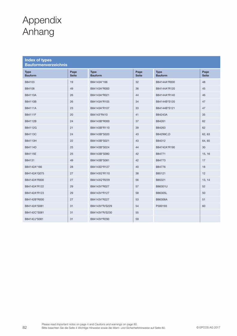
82 © EPCOS AG 2017Please read Important notes on page 4 and Cautions and warnings on page 80.Bitte beachten Sie die Seite 4 Wichtige Hinweise sowie die Warn- und Sicherheitshinweise auf Seite 80.
AppendixAnhang
Index of typesBauformenverzeichnis
TypeBauform
PageSeite
TypeBauform
PageSeite
TypeBauform
PageSeite
B84103 19 B84143A*166 32 B84144A*R000 48
B84108 49 B84143A*R000 36 B84144A*R120 45
B84110A 26 B84143A*R021 44 B84144A*R140 46
B84110B 26 B84143A*R105 34 B84144B*S120 47
B84111A 23 B84143A*R107 33 B84144B*S121 47
B84111F 20 B84143*R410 41 B84243A 35
B84112B 24 B84143B*R000 37 B84261 62
B84112G 21 B84143B*R110 39 B84263 62
B84113C 24 B84143B*S020 43 B84299C,D 62, 63
B84113H 22 B84143B*S021 43 B84312 64, 65
B84114D 25 B84143B*S024 44 B84742A*R190 30
B84115E 25 B84143B*S080 42 B84771 15, 16
B84131 49 B84143B*S081 42 B84773 17
B84142A*166 28 B84143D*R127 40 B84776 18
B84142A*G075 27 B84143G*R110 38 B85121 12
B84142A*R000 27 B84143Q*R229 56 B85321 13, 14
B84142A*R122 29 B84143V*R027 57 B86301U 52
B84142A*R123 29 B84143V*R127 58 B86305L 50
B84142B*R000 27 B84143V*R227 53 B86306A 51
B84142A*S081 31 B84143V*R/S229 54 P300193 60
B84142C*S081 31 B84143V*R/S230 55
B84142J*S081 31 B84143V*R290 59
EuropeAustriaTDK Austria GesmbHT +43 1 25 63 630 56 39F +43 1 25 63 630 56 [email protected]
Bulgaria, Greece, MacedoniaTDK Austria GesmbHT +43 1 25 63 630 56 30F +43 1 25 63 630 56 [email protected]
Czech RepublicTDK Czech s.r.o.T +420 2 33 03 22 81F +420 2 33 03 22 [email protected]
Finland, EstoniaTDK Nordic OYT +358 10 34 90 [email protected]
France, Belgium, Luxembourg,MaltaTDK Electronics France SAST +33 1 49 46 67 89F +33 1 49 46 67 [email protected]
Germany, Liechtenstein,Netherlands, SwitzerlandTDK Europe GmbHT (D) 0180 500 33 48
(0.14 Euro/min.)(NL) +31 70 33 10 611(CH) +49 89 54020 2691
F +49 89 54020 [email protected]
HungaryTDK Electronics Hungary Ltd.T +36 1 436 07 20F +36 1 436 07 [email protected]
ItalyTDK Italy S.r.lT +39 02 50 99 54 25F +39 02 50 99 54 [email protected]
Poland, Latvia, LithuaniaTDK Polska Sp. z o.o.T +48 22 24 60 409F +48 22 24 60 [email protected]
PortugalTDK Electronics Spain S.L.U.T +34 93 480 42 92
+34 93 480 42 68F +34 93 480 42 [email protected]
RomaniaTDK Austria GesmbHT +43 1 25 63 630 56 30F +43 1 25 63 630 56 [email protected]
Russia, Belarus, Kazakhstan,Moldavia, UkraineTDK CIS LLCT +7 495 663 21 00
+7 495 663 21 [email protected]
SlovakiaTDK Austria GesmbHT +43 1 25 63 630 56 30F +43 1 25 63 630 56 [email protected]
Bosnia and Herzegovina,Croatia, Montenegro, Serbia,SloveniaTDK Austria GesmbHT +43 1 25 63 630 56 30F +43 1 25 63 630 56 [email protected]
SpainTDK Electronics Spain S.L.U.T +34 93 480 42 92
+34 93 480 43 33F +34 91 514 70 [email protected]
Sweden, Iceland, Denmark,NorwayTDK Nordic ABT +46 8 4 77 27 00F +46 8 4 77 27 [email protected]
TurkeyTDK Europe GmbHT +90 216 5 69 81 01F +90 216 4 64 07 [email protected]
United Kingdom, IrelandTDK UK LimitedT +44 13 44 38 15 10F +44 13 44 38 15 [email protected]
AsiaAfghanistan, Iran, Iraq, Jordan,Lebanon, Pakistan, SyriaTDK Europe GmbHT +90 216 5 69 81 01F +90 216 4 64 07 [email protected]
ChinaEPCOS (Shanghai) Ltd.T +86 21 22 19 15 00F +86 21 22 19 15 [email protected]
Hong KongEPCOS LimitedT +852 36 69 82 00F +852 36 69 82 [email protected]
India, Bahrain, Bangladesh,Kuwait, Nepal, Oman, Qatar,Saudi Arabia, Sri Lanka,United Arab EmiratesEPCOS India Private Ltd.T +91 120 45 05 801F +91 120 45 05 [email protected]
IsraelTDK Sales RepresentativeT +972 73 2676 [email protected]
JapanTDK CorporationT +81 3 68 52 73 [email protected]
KoreaTDK Electronics KoreaCorporationT +82 2 30 19 43 00F +82 2 30 19 43 [email protected]
MalaysiaEPCOS RDC SDN. BHD.T +60 6 79 98 168F +60 6 79 98 [email protected]
Philippinesc/o TDK Electronics PhilippinesCorporationT +63 49 541 31 41 66 30
+63 49 541 31 41 66 31F +63 49 541 31 [email protected]
Singapore, Indonesia,Thailand, VietnamEPCOS COMPONENTS PTE.LTD.T +65 65 97 06 28F +65 65 97 06 [email protected]
TaiwanEPCOS Taiwan Co. Ltd.T +886 2 26 55 76 76F +886 2 27 82 03 [email protected]
AmericasUSA, Canada, MexicoEPCOS Inc.T +1 732 9 06 43 00F +1 732 9 06 43 [email protected]
South AmericaEPCOS do Brasil Ltda.T +55 11 32 89 95 99 Ext. 6851F +55 11 32 89 99 [email protected]
AustraliaAustralia, New ZealandTDK Sales RepresentativeT +61 3 95 66 72 17F +61 3 95 66 72 [email protected]
AfricaEgyptTDK Europe GmbHT +90 216 5 69 81 01F +90 216 4 64 07 [email protected]
Morocco, TunisiaTDK Electronics France SAST +33 1 49 46 67 89F +33 1 49 46 67 [email protected]
South AfricaTDK Sales RepresentativeT +27 11 458 90 00
+27 11 458 90 32F +27 11 458 90 [email protected]
11/2017
© EPCOS AG 2017, Corporate Communications, P.O.Box 80 17 09, 81617 Munich, GermanyReproduction, publication and dissemination of this publication and the information contained therein without EPCOS' prior express consent is prohibited.
The addresses of our worldwide distributors and regional sales offices are available at www.epcos.com/sales
Get in Contact

© EPCOS AG · A TDK Group CompanyEdition 2018 · Ordering No. EPC:32026-7400 · Printed in Germany · PS 12171.5