Embed Size (px)
Citation preview
Titulació:
Enginyeria en Organització Industrial
Alumne (nom i cognoms):
MARC DEIROS LLINÀS DEL TORRENT
Títol PFC:
Estudi de viabilitat d’una empresa de reforços de formigó amb
materials compostos
Director del PFC:
Lluís Gil Espert
Convocatòria de lliurament del PFC:
JUNY 2013
Contingut d’aquest volum: -ANNEXES-
Estudi de Viabilitat d’una
Empresa de Reforços de
Formigó amb Materials
Compostos
ANNEXES
Autor: Marc Deiros Llinàs del Torrent
Tutor: Lluis Gil Espert
Titulació: Enginyeria en Organització Industrial
Juny 2013
ANNEX: Estudi de viabilitat d'una empresa de reforços de formigó amb materials compostos
- AM3 -
ÍNDEX ANNEXES
ANNEX 1: INSPECCIÓ TÈCNICA D’EDIFICIS .................................................... 5
ANNEX 2: ESTADÍSTIQUES ANTIGUITAT EDIFICIS ......................................... 6
ANNEX 3: REHABILITACIÓ A CATALUNYA ....................................................... 8
ANNEX 4: AJUDES REHABILITACIÓ ESPANYA ................................................ 9
ANNEX 5: ARTICLE “EL MUNDO” NOU PLA .................................................... 18
ANNEX 6: COMPARACIÓ CFRP - ACER .......................................................... 20
ANNEX 7: ACI 440.2R-02 .................................................................................. 21
ANNEX 8: EXEMPLES APLICACIÓ ................................................................... 67
ANNEX 9: “PUNT VERD” GESTIÓ RESIDUS .................................................... 69
ANNEX 10: COMPROVANT NOM SOCIETAT DISPONIBLE ............................ 73
ANNEX 11: COMPETIDORS PRIMERA ETAPA ................................................ 74
ANNEX 12: COMPETIDORS SEGONA ETAPA ................................................. 81
ANNEX 13: NORMES ARTICLE “INFORMES DE LA CONSTRUCCIÓN” ......... 85
ANNEX 14: CÀLCUL PRESSUPOSTOS ........................................................... 88
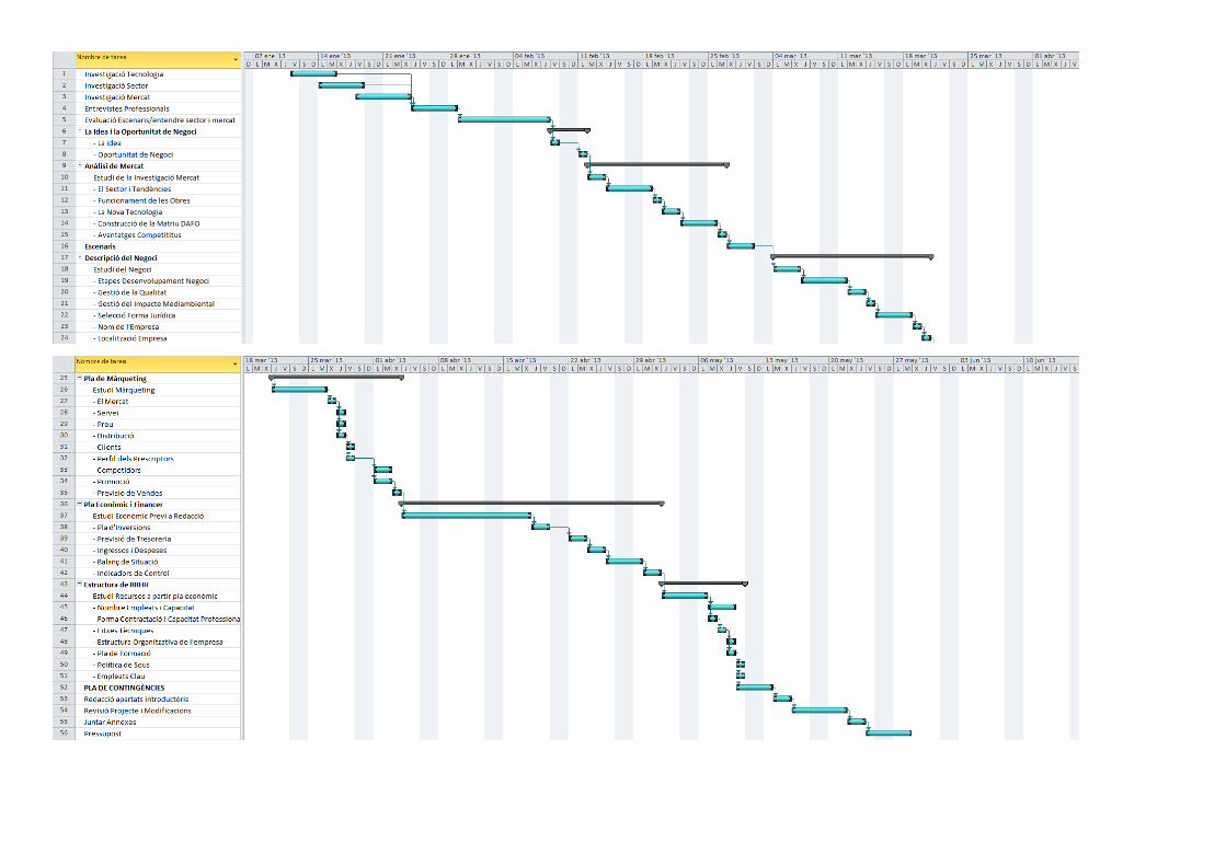
ANNEX 15: PLANIFICACIÓ PROJECTE ........................................................... 90

ANNEX: Estudi de viabilitat d'una empresa de reforços de formigó amb materials compostos
- AM4 -
ANNEX: Estudi de viabilitat d'una empresa de reforços de formigó amb materials compostos
- AM5 -
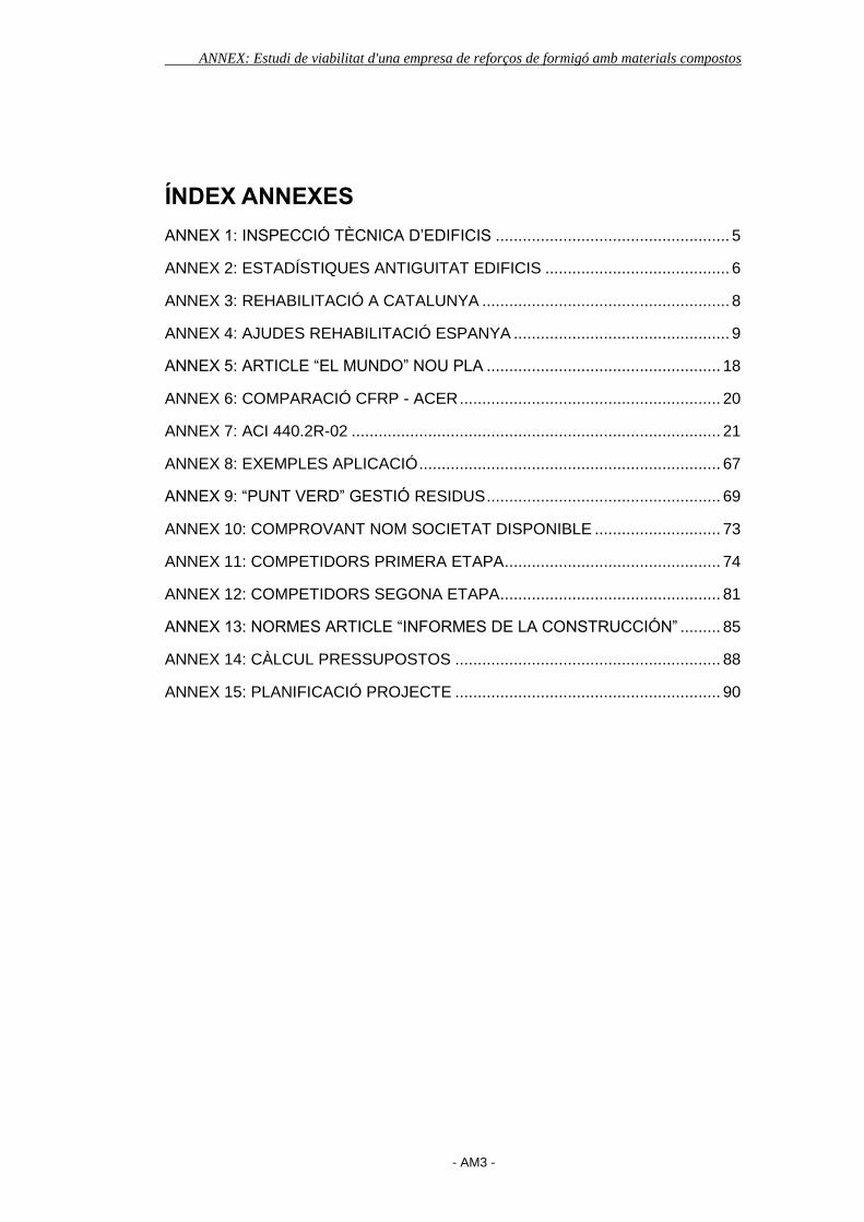
ANNEX 1: INSPECCIÓ TÈCNICA D’EDIFICIS
ANNEX: Estudi de viabilitat d'una empresa de reforços de formigó amb materials compostos
- AM6 -
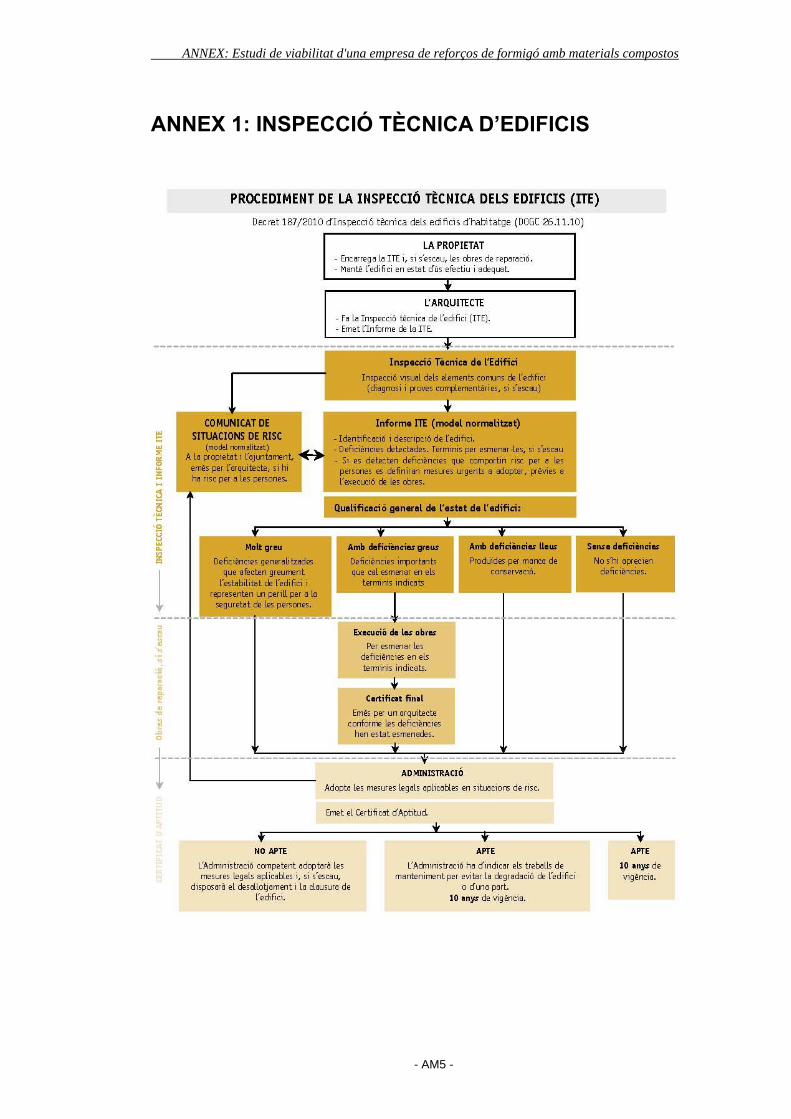
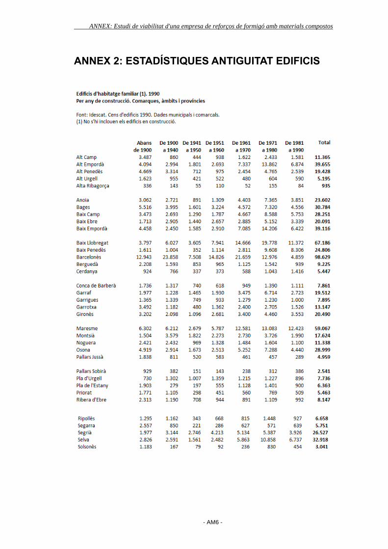
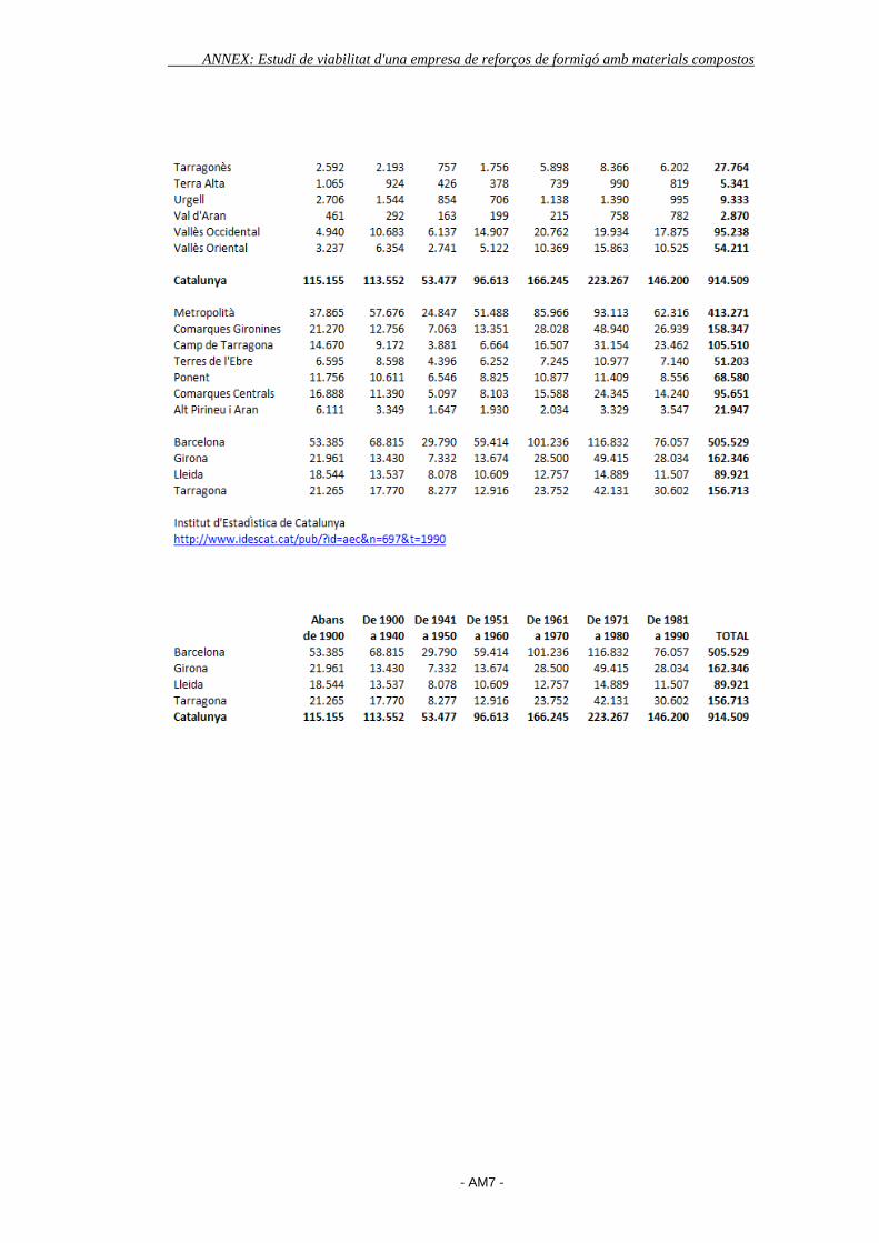
ANNEX 2: ESTADÍSTIQUES ANTIGUITAT EDIFICIS
ANNEX: Estudi de viabilitat d'una empresa de reforços de formigó amb materials compostos
- AM7 -
ANNEX: Estudi de viabilitat d'una empresa de reforços de formigó amb materials compostos
- AM8 -
ANNEX 3: REHABILITACIÓ A CATALUNYA
http://www.324.cat/noticia/1252326/economia/La-rehabilitacio-dedificis-salva-
part-del-sector-de-la-construccio
ANNEX: Estudi de viabilitat d'una empresa de reforços de formigó amb materials compostos
- AM9 -
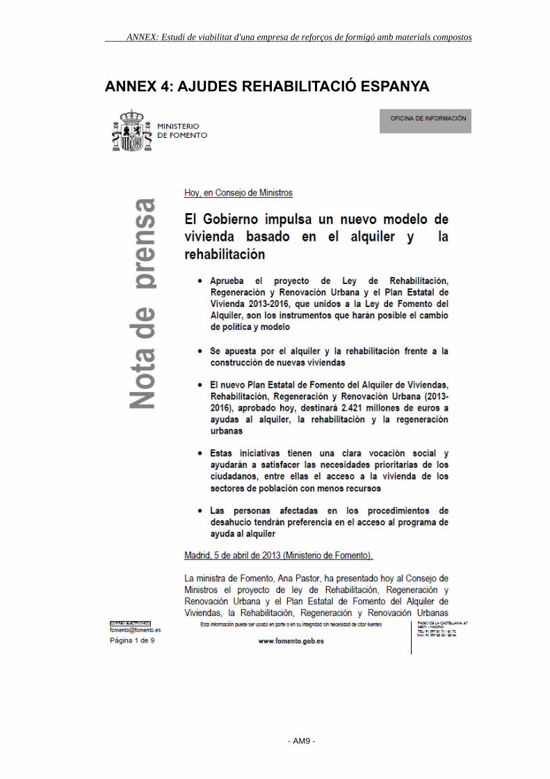
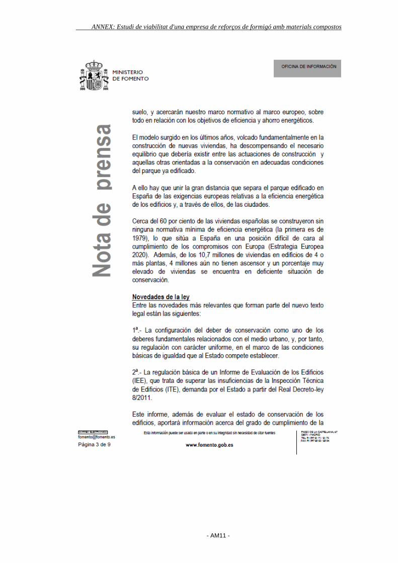
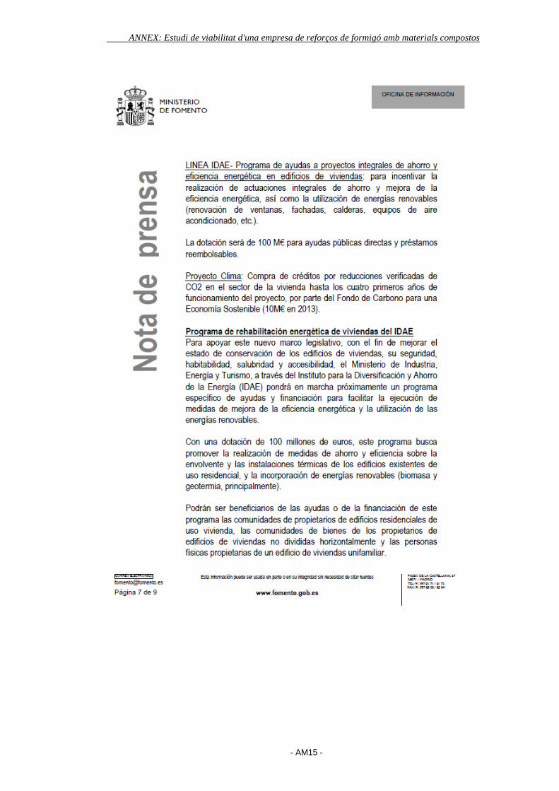
ANNEX 4: AJUDES REHABILITACIÓ ESPANYA

ANNEX: Estudi de viabilitat d'una empresa de reforços de formigó amb materials compostos
- AM10 -
ANNEX: Estudi de viabilitat d'una empresa de reforços de formigó amb materials compostos
- AM11 -

ANNEX: Estudi de viabilitat d'una empresa de reforços de formigó amb materials compostos
- AM12 -

ANNEX: Estudi de viabilitat d'una empresa de reforços de formigó amb materials compostos
- AM13 -

ANNEX: Estudi de viabilitat d'una empresa de reforços de formigó amb materials compostos
- AM14 -
ANNEX: Estudi de viabilitat d'una empresa de reforços de formigó amb materials compostos
- AM15 -
ANNEX: Estudi de viabilitat d'una empresa de reforços de formigó amb materials compostos
- AM16 -
ANNEX: Estudi de viabilitat d'una empresa de reforços de formigó amb materials compostos
- AM17 -

ANNEX: Estudi de viabilitat d'una empresa de reforços de formigó amb materials compostos
- AM18 -
ANNEX 5: ARTICLE “EL MUNDO” NOU PLA
http://www.elmundo.es/elmundo/2012/12/19/suvivienda/1355922963.html

ANNEX: Estudi de viabilitat d'una empresa de reforços de formigó amb materials compostos
- AM19 -
ANNEX: Estudi de viabilitat d'una empresa de reforços de formigó amb materials compostos
- AM20 -
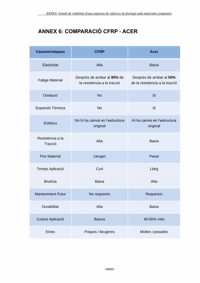
ANNEX 6: COMPARACIÓ CFRP - ACER
Característiques CFRP Acer
Elasticitat Alta Baixa
Fatiga Material Després de arribar al 90% de
la resistència a la tracció
Després de arribar al 50%
de la resistència a la tracció
Oxidació No Si
Expansió Tèrmica No Si
Estètica No hi ha canvis en l’estructura
original
Hi ha canvis en l’estructura
original
Resistència a la
Tracció Alta Baixa
Pes Material Lleuger Pesat
Temps Aplicació Curt Llarg
Brutícia Baixa Alta
Manteniment Futur No requereix Requereix
Durabilitat Alta Baixa
Costos Aplicació Baixos 40-50% més
Eines Poques i lleugeres Moltes i pesades
ANNEX: Estudi de viabilitat d'una empresa de reforços de formigó amb materials compostos
- AM21 -
ANNEX 7: ACI 440.2R-02
ANNEX: Estudi de viabilitat d'una empresa de reforços de formigó amb materials compostos
- AM22 -
ACI 440.2R-02 became effective July 11, 2002.Copyright 2002, American Concrete Institute.All rights reserved including rights of reproduction and use in any form or by any
means, including the making of copies by any photo process, or by electronic ormechanical device, printed, written, or oral, or recording for sound or visual reproductionor for use in any knowledge or retrieval system or device, unless permission in writingis obtained from the copyright proprietors.
ACI Committee Reports, Guides, Standard Practices,and Commentaries are intended for guidance in plan-ning, designing, executing, and inspecting construction.This document is intended for the use of individuals whoare competent to evaluate the significance and limita-tions of its content and recommendations and who willaccept responsibility for the application of the materialit contains. The American Concrete Institute disclaimsany and all responsibility for the stated principles. TheInstitute shall not be liable for any loss or damage arisingtherefrom.
Reference to this document shall not be made in con-tract documents. If items found in this document are de-sired by the Architect/Engineer to be a part of thecontract documents, they shall be restated in mandatorylanguage for incorporation by the Architect/Engineer.
440.2R-1
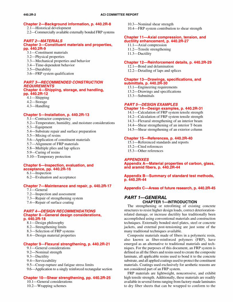
Guide for the Design and Construction ofExternally Bonded FRP Systems forStrengthening Concrete Structures
ACI 440.2R-02
Fiber-reinforced polymer (FRP) systems for strengthening concrete structureshave emerged as an alternative to traditional strengthening techniques, suchas steel plate bonding, section enlargement, and external post-tensioning.FRP strengthening systems use FRP composite materials as supplementalexternally bonded reinforcement. FRP systems offer advantages over traditionalstrengthening techniques: they are lightweight, relatively easy to install, andare noncorrosive. Due to the characteristics of FRP materials, the behaviorof FRP strengthened members, and various issues regarding the use ofexternally bonded reinforcement, specific guidance on the use of these systems
is needed. This document offers general information on the history and use ofFRP strengthening systems; a description of the unique material properties ofFRP; and committee recommendations on the engineering, construction, andinspection of FRP systems used to strengthen concrete structures. Theproposed guidelines are based on the knowledge gained from worldwideexperimental research, analytical work, and field applications of FRPsystems used to strengthen concrete structures.
Keywords: aramid fibers; bridges; buildings; carbon fibers; concrete; corro-sion; crack widths; cracking; cyclic loading; deflections; development length;earthquake-resistant; fatigue; fiber-reinforced polymers; flexure; glass fiber;shear; stresses; structural analysis; structural design; time-dependent; torsion.
CONTENTSPART 1—GENERALChapter 1—Introduction, p. 440.2R-2
1.1—Scope and limitations1.2—Applications and use1.3—Use of proprietary FRP systems1.4—Definitions and acronyms1.5—Notation
Charles E. Bakis Ali Ganjehlou Damian I. Kachlakev Morris SchupackP. N. Balaguru Duane J. Gee Vistasp M. Karbhari David W. Scott
Craig A. Ballinger T. Russell Gentry Howard S. Kliger Rajan SenLawrence C. Bank Arie Gerritse James G. Korff Mohsen A. ShahawyAbdeldjelil Belarbi Karl Gillette Michael W. Lee Carol K. Shield
Brahim Benmokrane William J. Gold* Ibrahim Mahfouz Khaled A. Soudki
Gregg J. Blaszak* Charles H. Goodspeed, III Henry N. Marsh, Jr. Luc R. TaerweGordon L. Brown, Jr. Nabil F. Grace Orange S. Marshall Jay Thomas
Vicki L. Brown Mark F. Green Amir Mirmiran Houssam A. ToutanjiThomas I. Campbell Mark E. Greenwood Ayman S. Mosallam Taketo Uomoto
Charles W. Dolan Doug D. Gremel Antoine E. Naaman Miroslav VadovicDat Duthinh Michael S. Guglielmo Antonio Nanni David R. Vanderpool
Rami M. Elhassan Issam E. Harik Kenneth Neale Milan VatovecSalem S. Faza Mark P. Henderson Edward F. O’Neil, III Stephanie L. Walkup
Edward R. Fyfe Bohdan N. Horeczko Max L. Porter David WhiteDavid M. Gale Srinivasa L. Iyer
Sami H. RizkallaChair
John P. BuselSecretary
*Co-chairs of the subcommittee that prepared this document.Note: The committee acknowledges the contribution of associate member Paul Kelley.
ACI encourages the development and appropriate use of new and emerging technologies through the publication of the Emerging TechnologySeries. This series presents information and recommendations based on available test data, technical reports, limited experience with fieldapplications, and the opinions of committee members. The presented information and recommendations, and their basis, may be less fully de-veloped and tested than those for more mature technologies. This report identifies areas in which information is believed to be less fully de-veloped, and describes research needs. The professional using this document should understand the limitations of this document and exercisejudgment as to the appropriate application of this emerging technology.
Reported by ACI Committee 440
440.2R-2 ACI COMMITTEE REPORT
Chapter 2—Background information, p. 440.2R-82.1—Historical development2.2—Commercially available externally bonded FRP systems
PART 2—MATERIALSChapter 3—Constituent materials and properties, pp. 440.2R-9
3.1—Constituent materials3.2—Physical properties3.3—Mechanical properties and behavior3.4—Time-dependent behavior3.5—Durability3.6—FRP system qualification
PART 3—RECOMMENDED CONSTRUCTION REQUIREMENTSChapter 4—Shipping, storage, and handling,pp. 440.2R-12
4.1—Shipping4.2—Storage4.3—Handling
Chapter 5—Installation, p. 440.2R-135.1—Contractor competency5.2—Temperature, humidity, and moisture considerations5.3—Equipment5.4—Substrate repair and surface preparation5.5—Mixing of resins5.6—Application of constituent materials5.7—Alignment of FRP materials5.8—Multiple plies and lap splices5.9—Curing of resins5.10—Temporary protection
Chapter 6—Inspection, evaluation, and acceptance, pp. 440.2R-16
6.1—Inspection6.2—Evaluation and acceptance
Chapter 7—Maintenance and repair, p. 440.2R-177.1—General7.2—Inspection and assessment7.3—Repair of strengthening system7.4—Repair of surface coating
PART 4—DESIGN RECOMMENDATIONSChapter 8—General design considerations,p. 440.2R-18
8.1—Design philosophy8.2—Strengthening limits8.3—Selection of FRP systems8.4—Design material properties
Chapter 9—Flexural strengthening, p. 440.2R-219.1—General considerations9.2—Nominal strength9.3—Ductility9.4—Serviceability9.5—Creep-rupture and fatigue stress limits9.6—Application to a singly reinforced rectangular section
Chapter 10—Shear strengthening, pp. 440.2R-2510.1—General considerations10.2—Wrapping schemes
10.3—Nominal shear strength10.4—FRP system contribution to shear strength
Chapter 11—Axial compression, tension, and ductility enhancement, p. 440.2R-27
11.1—Axial compression11.2—Tensile strengthening11.3—Ductility
Chapter 12—Reinforcement details, p. 440.2R-2912.1—Bond and delamination12.2—Detailing of laps and splices
Chapter 13—Drawings, specifications, and submittals, p. 440.2R-30
13.1—Engineering requirements13.2—Drawings and specifications13.3—Submittals
PART 5—DESIGN EXAMPLESChapter 14—Design examples, p. 440.2R-31
14.1—Calculation of FRP system tensile strength14.2—Calculation of FRP system tensile strength14.3—Flexural strengthening of an interior beam14.4—Shear strengthening of an interior T-beam14.5—Shear strengthening of an exterior column
Chapter 15—References, p. 440.2R-4015.1—Referenced standards and reports15.2—Cited references15.3—Other references
APPENDIXESAppendix A—Material properties of carbon, glass, and aramid fibers, p. 440.2R-44
Appendix B—Summary of standard test methods, p. 440.2R-44
Appendix C—Areas of future research, p. 440.2R-45
PART 1—GENERALCHAPTER 1—INTRODUCTION
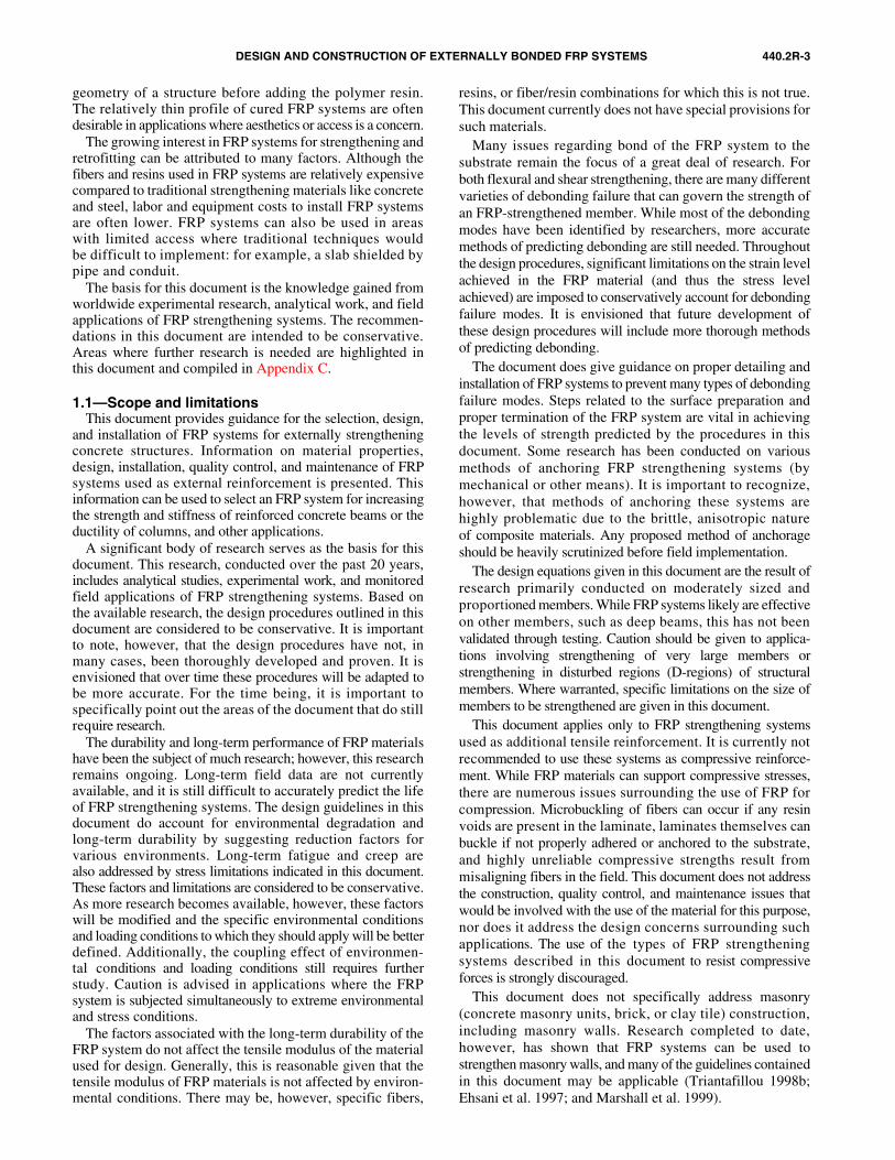
The strengthening or retrofitting of existing concretestructures to resist higher design loads, correct deterioration-related damage, or increase ductility has traditionally beenaccomplished using conventional materials and constructiontechniques. Externally bonded steel plates, steel or concretejackets, and external post-tensioning are just some of themany traditional techniques available.
Composite materials made of fibers in a polymeric resin,also known as fiber-reinforced polymers (FRP), haveemerged as an alternative to traditional materials and tech-niques. For the purposes of this document, an FRP system isdefined as all the fibers and resins used to create the compositelaminate, all applicable resins used to bond it to the concretesubstrate, and all applied coatings used to protect the constituentmaterials. Coatings used exclusively for aesthetic reasons arenot considered part of an FRP system.
FRP materials are lightweight, noncorrosive, and exhibithigh tensile strength. Additionally, these materials are readilyavailable in several forms ranging from factory-made laminatesto dry fiber sheets that can be wrapped to conform to the
DESIGN AND CONSTRUCTION OF EXTERNALLY BONDED FRP SYSTEMS 440.2R-3
geometry of a structure before adding the polymer resin.The relatively thin profile of cured FRP systems are oftendesirable in applications where aesthetics or access is a concern.
The growing interest in FRP systems for strengthening andretrofitting can be attributed to many factors. Although thefibers and resins used in FRP systems are relatively expensivecompared to traditional strengthening materials like concreteand steel, labor and equipment costs to install FRP systemsare often lower. FRP systems can also be used in areaswith limited access where traditional techniques wouldbe difficult to implement: for example, a slab shielded bypipe and conduit.
The basis for this document is the knowledge gained fromworldwide experimental research, analytical work, and fieldapplications of FRP strengthening systems. The recommen-dations in this document are intended to be conservative.Areas where further research is needed are highlighted inthis document and compiled in Appendix C.
1.1—Scope and limitationsThis document provides guidance for the selection, design,
and installation of FRP systems for externally strengtheningconcrete structures. Information on material properties,design, installation, quality control, and maintenance of FRPsystems used as external reinforcement is presented. Thisinformation can be used to select an FRP system for increasingthe strength and stiffness of reinforced concrete beams or theductility of columns, and other applications.
A significant body of research serves as the basis for thisdocument. This research, conducted over the past 20 years,includes analytical studies, experimental work, and monitoredfield applications of FRP strengthening systems. Based onthe available research, the design procedures outlined in thisdocument are considered to be conservative. It is importantto note, however, that the design procedures have not, inmany cases, been thoroughly developed and proven. It isenvisioned that over time these procedures will be adapted tobe more accurate. For the time being, it is important tospecifically point out the areas of the document that do stillrequire research.
The durability and long-term performance of FRP materialshave been the subject of much research; however, this researchremains ongoing. Long-term field data are not currentlyavailable, and it is still difficult to accurately predict the lifeof FRP strengthening systems. The design guidelines in thisdocument do account for environmental degradation andlong-term durability by suggesting reduction factors forvarious environments. Long-term fatigue and creep arealso addressed by stress limitations indicated in this document.These factors and limitations are considered to be conservative.As more research becomes available, however, these factorswill be modified and the specific environmental conditionsand loading conditions to which they should apply will be betterdefined. Additionally, the coupling effect of environmen-tal conditions and loading conditions still requires furtherstudy. Caution is advised in applications where the FRPsystem is subjected simultaneously to extreme environmentaland stress conditions.
The factors associated with the long-term durability of theFRP system do not affect the tensile modulus of the materialused for design. Generally, this is reasonable given that thetensile modulus of FRP materials is not affected by environ-mental conditions. There may be, however, specific fibers,
resins, or fiber/resin combinations for which this is not true.This document currently does not have special provisions forsuch materials.
Many issues regarding bond of the FRP system to thesubstrate remain the focus of a great deal of research. Forboth flexural and shear strengthening, there are many differentvarieties of debonding failure that can govern the strength ofan FRP-strengthened member. While most of the debondingmodes have been identified by researchers, more accuratemethods of predicting debonding are still needed. Throughoutthe design procedures, significant limitations on the strain levelachieved in the FRP material (and thus the stress levelachieved) are imposed to conservatively account for debondingfailure modes. It is envisioned that future development ofthese design procedures will include more thorough methodsof predicting debonding.
The document does give guidance on proper detailing andinstallation of FRP systems to prevent many types of debondingfailure modes. Steps related to the surface preparation andproper termination of the FRP system are vital in achievingthe levels of strength predicted by the procedures in thisdocument. Some research has been conducted on variousmethods of anchoring FRP strengthening systems (bymechanical or other means). It is important to recognize,however, that methods of anchoring these systems arehighly problematic due to the brittle, anisotropic natureof composite materials. Any proposed method of anchorageshould be heavily scrutinized before field implementation.
The design equations given in this document are the result ofresearch primarily conducted on moderately sized andproportioned members. While FRP systems likely are effectiveon other members, such as deep beams, this has not beenvalidated through testing. Caution should be given to applica-tions involving strengthening of very large members orstrengthening in disturbed regions (D-regions) of structuralmembers. Where warranted, specific limitations on the size ofmembers to be strengthened are given in this document.
This document applies only to FRP strengthening systemsused as additional tensile reinforcement. It is currently notrecommended to use these systems as compressive reinforce-ment. While FRP materials can support compressive stresses,there are numerous issues surrounding the use of FRP forcompression. Microbuckling of fibers can occur if any resinvoids are present in the laminate, laminates themselves canbuckle if not properly adhered or anchored to the substrate,and highly unreliable compressive strengths result frommisaligning fibers in the field. This document does not addressthe construction, quality control, and maintenance issues thatwould be involved with the use of the material for this purpose,nor does it address the design concerns surrounding suchapplications. The use of the types of FRP strengtheningsystems described in this document to resist compressiveforces is strongly discouraged.
This document does not specifically address masonry(concrete masonry units, brick, or clay tile) construction,including masonry walls. Research completed to date,however, has shown that FRP systems can be used tostrengthen masonry walls, and many of the guidelines containedin this document may be applicable (Triantafillou 1998b;Ehsani et al. 1997; and Marshall et al. 1999).
440.2R-4 ACI COMMITTEE REPORT
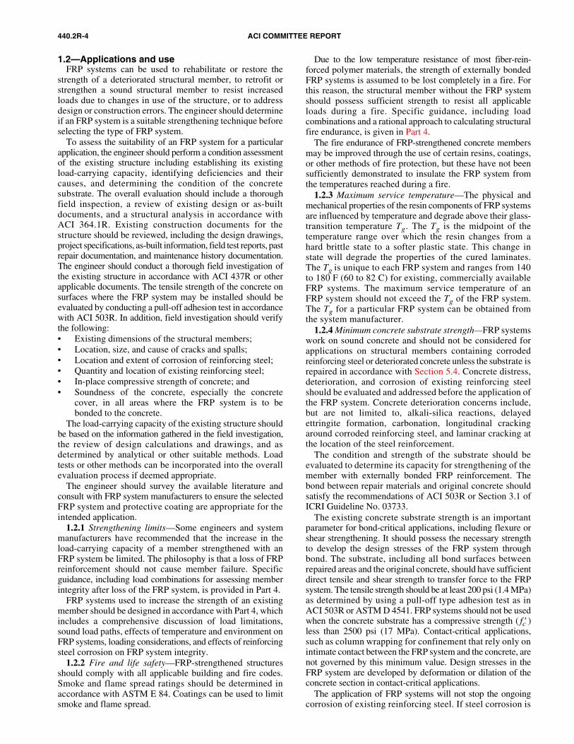
1.2—Applications and useFRP systems can be used to rehabilitate or restore the
strength of a deteriorated structural member, to retrofit orstrengthen a sound structural member to resist increasedloads due to changes in use of the structure, or to addressdesign or construction errors. The engineer should determineif an FRP system is a suitable strengthening technique beforeselecting the type of FRP system.
To assess the suitability of an FRP system for a particularapplication, the engineer should perform a condition assessmentof the existing structure including establishing its existingload-carrying capacity, identifying deficiencies and theircauses, and determining the condition of the concretesubstrate. The overall evaluation should include a thoroughfield inspection, a review of existing design or as-builtdocuments, and a structural analysis in accordance withACI 364.1R. Existing construction documents for thestructure should be reviewed, including the design drawings,project specifications, as-built information, field test reports, pastrepair documentation, and maintenance history documentation.The engineer should conduct a thorough field investigation ofthe existing structure in accordance with ACI 437R or otherapplicable documents. The tensile strength of the concrete onsurfaces where the FRP system may be installed should beevaluated by conducting a pull-off adhesion test in accordancewith ACI 503R. In addition, field investigation should verifythe following:• Existing dimensions of the structural members;• Location, size, and cause of cracks and spalls;• Location and extent of corrosion of reinforcing steel;• Quantity and location of existing reinforcing steel;• In-place compressive strength of concrete; and• Soundness of the concrete, especially the concrete
cover, in all areas where the FRP system is to bebonded to the concrete.
The load-carrying capacity of the existing structure shouldbe based on the information gathered in the field investigation,the review of design calculations and drawings, and asdetermined by analytical or other suitable methods. Loadtests or other methods can be incorporated into the overallevaluation process if deemed appropriate.
The engineer should survey the available literature andconsult with FRP system manufacturers to ensure the selectedFRP system and protective coating are appropriate for theintended application.
1.2.1 Strengthening limits—Some engineers and systemmanufacturers have recommended that the increase in theload-carrying capacity of a member strengthened with anFRP system be limited. The philosophy is that a loss of FRPreinforcement should not cause member failure. Specificguidance, including load combinations for assessing memberintegrity after loss of the FRP system, is provided in Part 4.
FRP systems used to increase the strength of an existingmember should be designed in accordance with Part 4, whichincludes a comprehensive discussion of load limitations,sound load paths, effects of temperature and environment onFRP systems, loading considerations, and effects of reinforcingsteel corrosion on FRP system integrity.
1.2.2 Fire and life safety—FRP-strengthened structuresshould comply with all applicable building and fire codes.Smoke and flame spread ratings should be determined inaccordance with ASTM E 84. Coatings can be used to limitsmoke and flame spread.
Due to the low temperature resistance of most fiber-rein-forced polymer materials, the strength of externally bondedFRP systems is assumed to be lost completely in a fire. Forthis reason, the structural member without the FRP systemshould possess sufficient strength to resist all applicableloads during a fire. Specific guidance, including loadcombinations and a rational approach to calculating structuralfire endurance, is given in Part 4.
The fire endurance of FRP-strengthened concrete membersmay be improved through the use of certain resins, coatings,or other methods of fire protection, but these have not beensufficiently demonstrated to insulate the FRP system fromthe temperatures reached during a fire.
1.2.3 Maximum service temperature—The physical andmechanical properties of the resin components of FRP systemsare influenced by temperature and degrade above their glass-transition temperature Tg. The Tg is the midpoint of thetemperature range over which the resin changes from ahard brittle state to a softer plastic state. This change instate will degrade the properties of the cured laminates.The Tg is unique to each FRP system and ranges from 140to 180 F (60 to 82 C) for existing, commercially availableFRP systems. The maximum service temperature of anFRP system should not exceed the Tg of the FRP system.The Tg for a particular FRP system can be obtained fromthe system manufacturer.
1.2.4 Minimum concrete substrate strength—FRP systemswork on sound concrete and should not be considered forapplications on structural members containing corrodedreinforcing steel or deteriorated concrete unless the substrate isrepaired in accordance with Section 5.4. Concrete distress,deterioration, and corrosion of existing reinforcing steelshould be evaluated and addressed before the application ofthe FRP system. Concrete deterioration concerns include,but are not limited to, alkali-silica reactions, delayedettringite formation, carbonation, longitudinal crackingaround corroded reinforcing steel, and laminar cracking atthe location of the steel reinforcement.
The condition and strength of the substrate should beevaluated to determine its capacity for strengthening of themember with externally bonded FRP reinforcement. Thebond between repair materials and original concrete shouldsatisfy the recommendations of ACI 503R or Section 3.1 ofICRI Guideline No. 03733.
The existing concrete substrate strength is an importantparameter for bond-critical applications, including flexure orshear strengthening. It should possess the necessary strengthto develop the design stresses of the FRP system throughbond. The substrate, including all bond surfaces betweenrepaired areas and the original concrete, should have sufficientdirect tensile and shear strength to transfer force to the FRPsystem. The tensile strength should be at least 200 psi (1.4 MPa)as determined by using a pull-off type adhesion test as inACI 503R or ASTM D 4541. FRP systems should not be usedwhen the concrete substrate has a compressive strength ( fc′ )less than 2500 psi (17 MPa). Contact-critical applications,such as column wrapping for confinement that rely only onintimate contact between the FRP system and the concrete, arenot governed by this minimum value. Design stresses in theFRP system are developed by deformation or dilation of theconcrete section in contact-critical applications.
The application of FRP systems will not stop the ongoingcorrosion of existing reinforcing steel. If steel corrosion is
DESIGN AND CONSTRUCTION OF EXTERNALLY BONDED FRP SYSTEMS 440.2R-5
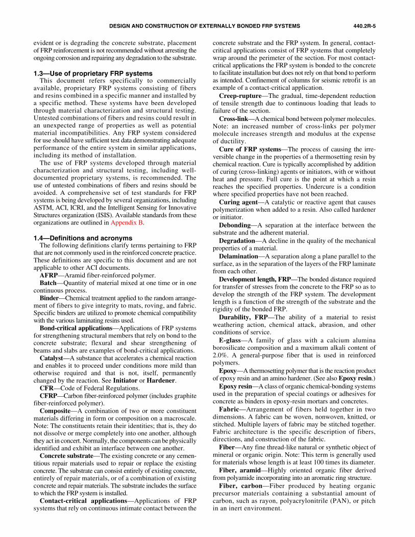
evident or is degrading the concrete substrate, placementof FRP reinforcement is not recommended without arresting theongoing corrosion and repairing any degradation to the substrate.
1.3—Use of proprietary FRP systemsThis document refers specifically to commercially
available, proprietary FRP systems consisting of fibersand resins combined in a specific manner and installed bya specific method. These systems have been developedthrough material characterization and structural testing.Untested combinations of fibers and resins could result inan unexpected range of properties as well as potentialmaterial incompatibilities. Any FRP system consideredfor use should have sufficient test data demonstrating adequateperformance of the entire system in similar applications,including its method of installation.
The use of FRP systems developed through materialcharacterization and structural testing, including well-documented proprietary systems, is recommended. Theuse of untested combinations of fibers and resins should beavoided. A comprehensive set of test standards for FRPsystems is being developed by several organizations, includingASTM, ACI, ICRI, and the Intelligent Sensing for InnovativeStructures organization (ISIS). Available standards from theseorganizations are outlined in Appendix B.
1.4—Definitions and acronymsThe following definitions clarify terms pertaining to FRP
that are not commonly used in the reinforced concrete practice.These definitions are specific to this document and are notapplicable to other ACI documents.
AFRP—Aramid fiber-reinforced polymer.Batch—Quantity of material mixed at one time or in one
continuous process.Binder—Chemical treatment applied to the random arrange-
ment of fibers to give integrity to mats, roving, and fabric.Specific binders are utilized to promote chemical compatibilitywith the various laminating resins used.
Bond-critical applications—Applications of FRP systemsfor strengthening structural members that rely on bond to theconcrete substrate; flexural and shear strengthening ofbeams and slabs are examples of bond-critical applications.
Catalyst—A substance that accelerates a chemical reactionand enables it to proceed under conditions more mild thanotherwise required and that is not, itself, permanentlychanged by the reaction. See Initiator or Hardener.
CFR—Code of Federal Regulations.CFRP—Carbon fiber-reinforced polymer (includes graphite
fiber-reinforced polymer).Composite—A combination of two or more constituent
materials differing in form or composition on a macroscale.Note: The constituents retain their identities; that is, they donot dissolve or merge completely into one another, althoughthey act in concert. Normally, the components can be physicallyidentified and exhibit an interface between one another.
Concrete substrate—The existing concrete or any cemen-titious repair materials used to repair or replace the existingconcrete. The substrate can consist entirely of existing concrete,entirely of repair materials, or of a combination of existingconcrete and repair materials. The substrate includes the surfaceto which the FRP system is installed.
Contact-critical applications—Applications of FRPsystems that rely on continuous intimate contact between the
concrete substrate and the FRP system. In general, contact-critical applications consist of FRP systems that completelywrap around the perimeter of the section. For most contact-critical applications the FRP system is bonded to the concreteto facilitate installation but does not rely on that bond to performas intended. Confinement of columns for seismic retrofit is anexample of a contact-critical application.
Creep-rupture—The gradual, time-dependent reductionof tensile strength due to continuous loading that leads tofailure of the section.
Cross-link—A chemical bond between polymer molecules.Note: an increased number of cross-links per polymermolecule increases strength and modulus at the expenseof ductility.
Cure of FRP systems—The process of causing the irre-versible change in the properties of a thermosetting resin bychemical reaction. Cure is typically accomplished by additionof curing (cross-linking) agents or initiators, with or withoutheat and pressure. Full cure is the point at which a resinreaches the specified properties. Undercure is a conditionwhere specified properties have not been reached.
Curing agent—A catalytic or reactive agent that causespolymerization when added to a resin. Also called hardeneror initiator.
Debonding—A separation at the interface between thesubstrate and the adherent material.
Degradation—A decline in the quality of the mechanicalproperties of a material.
Delamination—A separation along a plane parallel to thesurface, as in the separation of the layers of the FRP laminatefrom each other.
Development length, FRP—The bonded distance requiredfor transfer of stresses from the concrete to the FRP so as todevelop the strength of the FRP system. The developmentlength is a function of the strength of the substrate and therigidity of the bonded FRP.
Durability, FRP—The ability of a material to resistweathering action, chemical attack, abrasion, and otherconditions of service.
E-glass—A family of glass with a calcium aluminaborosilicate composition and a maximum alkali content of2.0%. A general-purpose fiber that is used in reinforcedpolymers.
Epoxy—A thermosetting polymer that is the reaction productof epoxy resin and an amino hardener. (See also Epoxy resin.)
Epoxy resin—A class of organic chemical-bonding systemsused in the preparation of special coatings or adhesives forconcrete as binders in epoxy-resin mortars and concretes.
Fabric—Arrangement of fibers held together in twodimensions. A fabric can be woven, nonwoven, knitted, orstitched. Multiple layers of fabric may be stitched together.Fabric architecture is the specific description of fibers,directions, and construction of the fabric.
Fiber—Any fine thread-like natural or synthetic object ofmineral or organic origin. Note: This term is generally usedfor materials whose length is at least 100 times its diameter.
Fiber, aramid—Highly oriented organic fiber derivedfrom polyamide incorporating into an aromatic ring structure.
Fiber, carbon—Fiber produced by heating organicprecursor materials containing a substantial amount ofcarbon, such as rayon, polyacrylonitrile (PAN), or pitchin an inert environment.
440.2R-6 ACI COMMITTEE REPORT
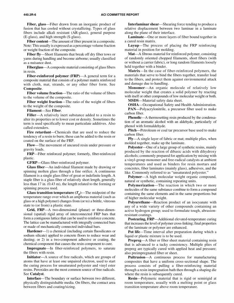
Fiber, glass—Fiber drawn from an inorganic product offusion that has cooled without crystallizing. Types of glassfibers include alkali resistant (AR-glass), general purpose(E-glass), and high strength (S-glass).
Fiber content—The amount of fiber present in a composite.Note: This usually is expressed as a percentage volume fractionor weight fraction of the composite.
Fiber fly—Short filaments that break off dry fiber tows oryarns during handling and become airborne; usually classifiedas a nuisance dust.
Fiberglass—A composite material consisting of glass fibersin resin.
Fiber-reinforced polymer (FRP)—A general term for acomposite material that consists of a polymer matrix reinforcedwith cloth, mat, strands, or any other fiber form. SeeComposite.
Fiber volume fraction—The ratio of the volume of fibersto the volume of the composite.
Fiber weight fraction—The ratio of the weight of fibersto the weight of the composite.
Filament—See Fiber.Filler—A relatively inert substance added to a resin to
alter its properties or to lower cost or density. Sometimes theterm is used specifically to mean particulate additives. Alsocalled extenders.
Fire retardant—Chemicals that are used to reduce thetendency of a resin to burn; these can be added to the resin orcoated on the surface of the FRP.
Flow—The movement of uncured resin under pressure orgravity loads.
FRP—Fiber reinforced polymer; formerly, fiber-reinforcedplastic.
GFRP—Glass fiber-reinforced polymer.Glass fiber—An individual filament made by drawing or
spinning molten glass through a fine orifice. A continuousfilament is a single glass fiber of great or indefinite length. Astaple fiber is a glass fiber of relatively short length, generallyless than 17 in. (0.43 m), the length related to the forming orspinning process used.
Glass transition temperature (Tg)—The midpoint of thetemperature range over which an amphoras material (such asglass or a high polymer) changes from (or to) a brittle, vitreousstate to (or from) a plastic state.
Grid, FRP—A two-dimensional (planar) or three-dimen-sional (spatial) rigid array of interconnected FRP bars thatform a contiguous lattice that can be used to reinforce concrete.The lattice can be manufactured with integrally connected barsor made of mechanically connected individual bars.
Hardener—1) a chemical (including certain fluosilicates orsodium silicate) applied to concrete floors to reduce wear anddusting; or 2) in a two-component adhesive or coating, thechemical component that causes the resin component to cure.
Impregnate—In fiber-reinforced polymers, to saturatethe fibers with resin.
Initiator—A source of free radicals, which are groups ofatoms that have at least one unpaired electron, used to startthe curing process for unsaturated polyester and vinyl esterresins. Peroxides are the most common source of free radicals.See Catalyst.
Interface—The boundary or surface between two different,physically distinguishable media. On fibers, the contact areabetween fibers and coating/sizing.
Interlaminar shear—Shearing force tending to produce arelative displacement between two laminae in a laminatealong the plane of their interface.
Laminate—One or more layers of fiber bound together ina cured resin matrix.
Layup—The process of placing the FRP reinforcingmaterial in position for molding.
Mat—A fibrous material for reinforced polymer, consistingof randomly oriented chopped filaments, short fibers (withor without a carrier fabric), or long random filaments looselyheld together with a binder.
Matrix—In the case of fiber-reinforced polymers, thematerials that serve to bind the fibers together, transfer loadto the fibers, and protect them against environmental attackand damage due to handling.
Monomer—An organic molecule of relatively lowmolecular weight that creates a solid polymer by reactingwith itself or other compounds of low molecular weight or both.
MSDS—Material safety data sheet.OSHA—Occupational Safety and Health Administration.PAN—Polyacrylonitrile, a precursor fiber used to make
carbon fiber.Phenolic—A thermosetting resin produced by the condensa-
tion of an aromatic alcohol with an aldehyde, particularly ofphenol with formaldehyde.
Pitch—Petroleum or coal tar precursor base used to makecarbon fiber.
Ply—A single layer of fabric or mat; multiple plies, whenmolded together, make up the laminate.
Polyester—One of a large group of synthetic resins, mainlyproduced by the reaction of dibasic acids with dihydroxyalcohols; commonly prepared for application by mixing witha vinyl-group monomer and free-radical catalysts at ambienttemperatures and used as binders for resin mortars andconcretes, fiber laminates (mainly glass), adhesives, and thelike. Commonly referred to as “unsaturated polyester.”
Polymer—A high molecular weight organic compound,natural or synthetic, containing repeating units.
Polymerization—The reaction in which two or moremolecules of the same substance combine to form a compoundcontaining the same elements and in the same proportions butof higher molecular weight.
Polyurethane—Reaction product of an isocyanate withany of a wide variety of other compounds containing anactive hydrogen group; used to formulate tough, abrasion-resistant coatings.
Postcuring, FRP—Additional elevated-temperature curingthat increases the level of polymer cross-linking; final propertiesof the laminate or polymer are enhanced.
Pot life—Time interval after preparation during which aliquid or plastic mixture is to be used.
Prepreg—A fiber or fiber sheet material containing resinthat is advanced to a tacky consistency. Multiple plies ofprepreg are typically cured with applied heat and pressure;also preimpregnated fiber or sheet.
Pultrusion—A continuous process for manufacturingcomposites that have a uniform cross-sectional shape. Theprocess consists of pulling a fiber-reinforcing materialthrough a resin impregnation bath then through a shaping diewhere the resin is subsequently cured.
Resin—Polymeric material that is rigid or semirigid atroom temperature, usually with a melting point or glasstransition temperature above room temperature.
DESIGN AND CONSTRUCTION OF EXTERNALLY BONDED FRP SYSTEMS 440.2R-7
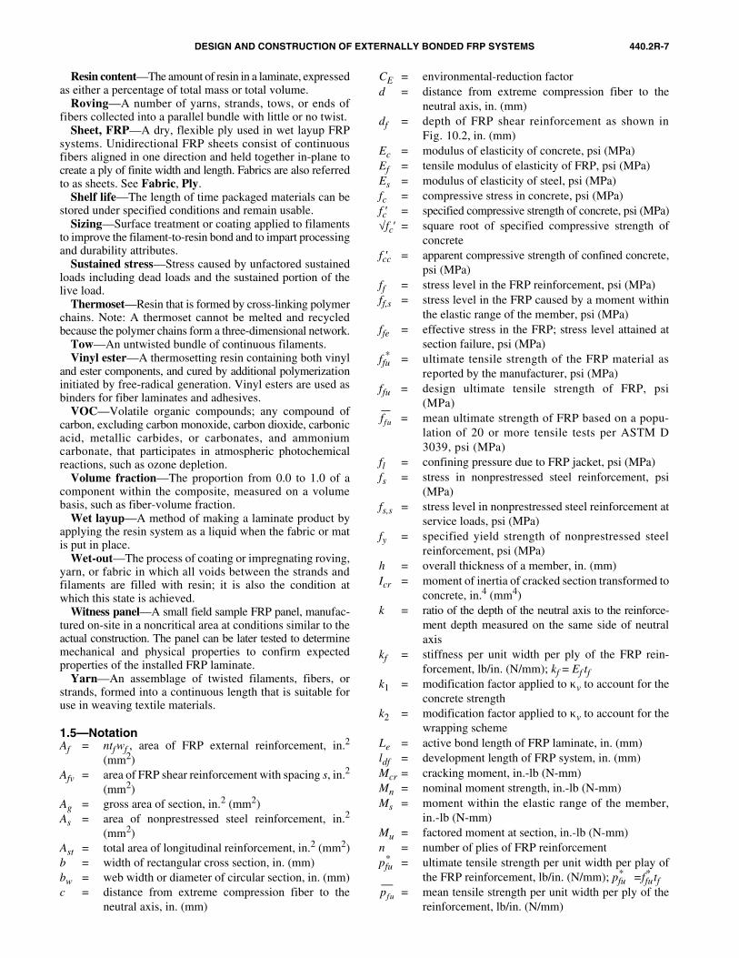
Resin content—The amount of resin in a laminate, expressedas either a percentage of total mass or total volume.
Roving—A number of yarns, strands, tows, or ends offibers collected into a parallel bundle with little or no twist.
Sheet, FRP—A dry, flexible ply used in wet layup FRPsystems. Unidirectional FRP sheets consist of continuousfibers aligned in one direction and held together in-plane tocreate a ply of finite width and length. Fabrics are also referredto as sheets. See Fabric, Ply.
Shelf life—The length of time packaged materials can bestored under specified conditions and remain usable.
Sizing—Surface treatment or coating applied to filamentsto improve the filament-to-resin bond and to impart processingand durability attributes.
Sustained stress—Stress caused by unfactored sustainedloads including dead loads and the sustained portion of thelive load.
Thermoset—Resin that is formed by cross-linking polymerchains. Note: A thermoset cannot be melted and recycledbecause the polymer chains form a three-dimensional network.
Tow—An untwisted bundle of continuous filaments. Vinyl ester—A thermosetting resin containing both vinyl
and ester components, and cured by additional polymerizationinitiated by free-radical generation. Vinyl esters are used asbinders for fiber laminates and adhesives.
VOC—Volatile organic compounds; any compound ofcarbon, excluding carbon monoxide, carbon dioxide, carbonicacid, metallic carbides, or carbonates, and ammoniumcarbonate, that participates in atmospheric photochemicalreactions, such as ozone depletion.
Volume fraction—The proportion from 0.0 to 1.0 of acomponent within the composite, measured on a volumebasis, such as fiber-volume fraction.
Wet layup—A method of making a laminate product byapplying the resin system as a liquid when the fabric or matis put in place.
Wet-out—The process of coating or impregnating roving,yarn, or fabric in which all voids between the strands andfilaments are filled with resin; it is also the condition atwhich this state is achieved.
Witness panel—A small field sample FRP panel, manufac-tured on-site in a noncritical area at conditions similar to theactual construction. The panel can be later tested to determinemechanical and physical properties to confirm expectedproperties of the installed FRP laminate.
Yarn—An assemblage of twisted filaments, fibers, orstrands, formed into a continuous length that is suitable foruse in weaving textile materials.
1.5—NotationAf = ntfwf , area of FRP external reinforcement, in.2
(mm2)Afv = area of FRP shear reinforcement with spacing s, in.2
(mm2)Ag = gross area of section, in.2 (mm2)As = area of nonprestressed steel reinforcement, in.2
(mm2)Ast = total area of longitudinal reinforcement, in.2 (mm2)b = width of rectangular cross section, in. (mm)bw = web width or diameter of circular section, in. (mm)c = distance from extreme compression fiber to the
neutral axis, in. (mm)
CE = environmental-reduction factord = distance from extreme compression fiber to the
neutral axis, in. (mm)df = depth of FRP shear reinforcement as shown in
Fig. 10.2, in. (mm)Ec = modulus of elasticity of concrete, psi (MPa)Ef = tensile modulus of elasticity of FRP, psi (MPa)Es = modulus of elasticity of steel, psi (MPa)fc = compressive stress in concrete, psi (MPa)fc′ = specified compressive strength of concrete, psi (MPa)√fc′ = square root of specified compressive strength of
concretefcc′ = apparent compressive strength of confined concrete,
psi (MPa)ff = stress level in the FRP reinforcement, psi (MPa)ff,s = stress level in the FRP caused by a moment within
the elastic range of the member, psi (MPa)ffe = effective stress in the FRP; stress level attained at
section failure, psi (MPa)ffu
* = ultimate tensile strength of the FRP material asreported by the manufacturer, psi (MPa)
ffu = design ultimate tensile strength of FRP, psi(MPa)
= mean ultimate strength of FRP based on a popu-lation of 20 or more tensile tests per ASTM D3039, psi (MPa)
fl = confining pressure due to FRP jacket, psi (MPa)fs = stress in nonprestressed steel reinforcement, psi
(MPa)fs,s = stress level in nonprestressed steel reinforcement at
service loads, psi (MPa)fy = specified yield strength of nonprestressed steel
reinforcement, psi (MPa)h = overall thickness of a member, in. (mm)Icr = moment of inertia of cracked section transformed to
concrete, in.4 (mm4)k = ratio of the depth of the neutral axis to the reinforce-
ment depth measured on the same side of neutralaxis
kf = stiffness per unit width per ply of the FRP rein-forcement, lb/in. (N/mm); kf = Ef tf
k1 = modification factor applied to κv to account for theconcrete strength
k2 = modification factor applied to κv to account for thewrapping scheme
Le = active bond length of FRP laminate, in. (mm)ldf = development length of FRP system, in. (mm)Mcr = cracking moment, in.-lb (N-mm)Mn = nominal moment strength, in.-lb (N-mm)Ms = moment within the elastic range of the member,
in.-lb (N-mm)Mu = factored moment at section, in.-lb (N-mm)n = number of plies of FRP reinforcementpfu
* = ultimate tensile strength per unit width per play ofthe FRP reinforcement, lb/in. (N/mm); pfu
* =ffu* tf
= mean tensile strength per unit width per ply of thereinforcement, lb/in. (N/mm)
ffu
pfu
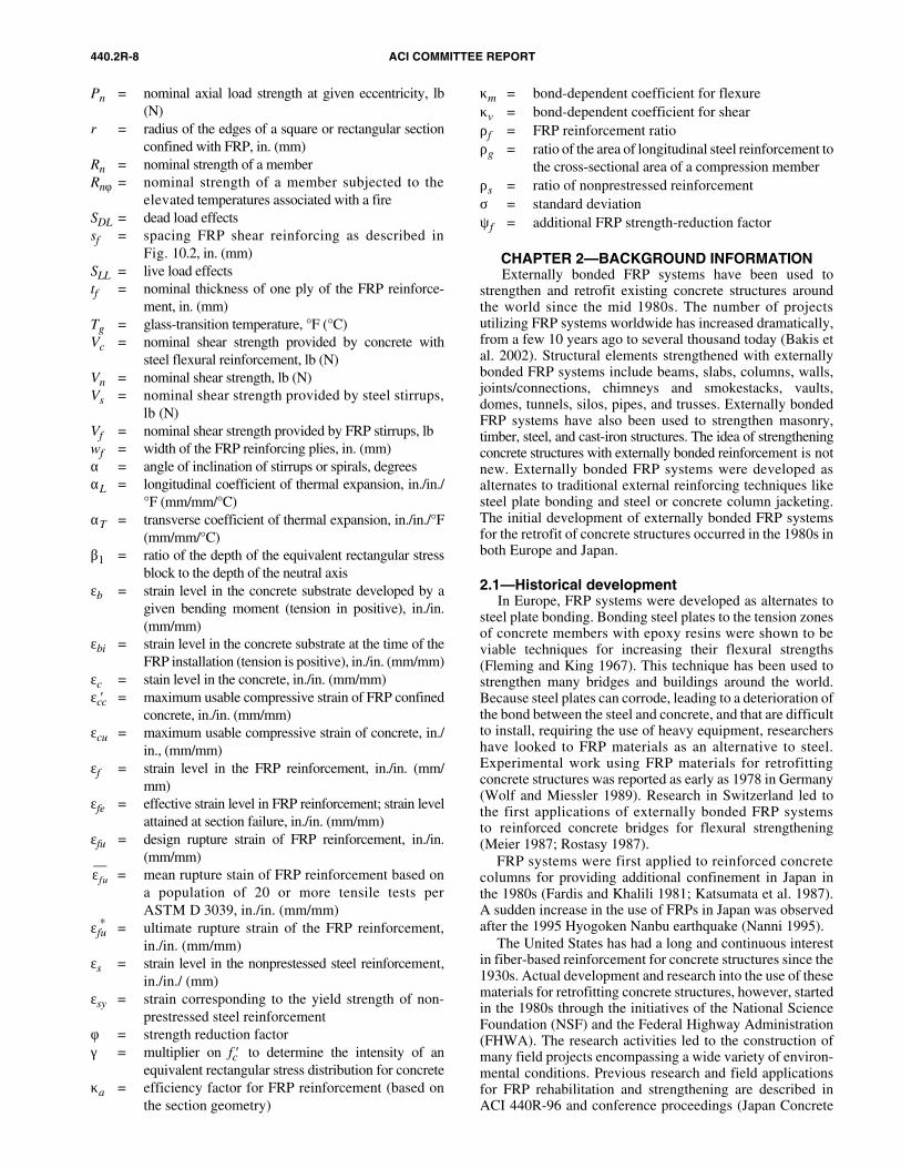
440.2R-8 ACI COMMITTEE REPORT
Pn = nominal axial load strength at given eccentricity, lb(N)
r = radius of the edges of a square or rectangular sectionconfined with FRP, in. (mm)
Rn = nominal strength of a memberRnφ = nominal strength of a member subjected to the
elevated temperatures associated with a fireSDL = dead load effectssf = spacing FRP shear reinforcing as described in
Fig. 10.2, in. (mm)SLL = live load effectstf = nominal thickness of one ply of the FRP reinforce-
ment, in. (mm)Tg = glass-transition temperature, °F (°C)Vc = nominal shear strength provided by concrete with
steel flexural reinforcement, lb (N)Vn = nominal shear strength, lb (N)Vs = nominal shear strength provided by steel stirrups,
lb (N)Vf = nominal shear strength provided by FRP stirrups, lbwf = width of the FRP reinforcing plies, in. (mm)α = angle of inclination of stirrups or spirals, degreesαL = longitudinal coefficient of thermal expansion, in./in./
°F (mm/mm/°C)αT = transverse coefficient of thermal expansion, in./in./°F
(mm/mm/°C)β1 = ratio of the depth of the equivalent rectangular stress
block to the depth of the neutral axisεb = strain level in the concrete substrate developed by a
given bending moment (tension in positive), in./in.(mm/mm)
εbi = strain level in the concrete substrate at the time of theFRP installation (tension is positive), in./in. (mm/mm)
εc = stain level in the concrete, in./in. (mm/mm)εcc′ = maximum usable compressive strain of FRP confined
concrete, in./in. (mm/mm)εcu = maximum usable compressive strain of concrete, in./
in., (mm/mm)εf = strain level in the FRP reinforcement, in./in. (mm/
mm)εfe = effective strain level in FRP reinforcement; strain level
attained at section failure, in./in. (mm/mm)εfu = design rupture strain of FRP reinforcement, in./in.
(mm/mm)= mean rupture stain of FRP reinforcement based on
a population of 20 or more tensile tests perASTM D 3039, in./in. (mm/mm)
εfu* = ultimate rupture strain of the FRP reinforcement,
in./in. (mm/mm)εs = strain level in the nonprestessed steel reinforcement,
in./in./ (mm)εsy = strain corresponding to the yield strength of non-
prestressed steel reinforcementφ = strength reduction factorγ = multiplier on fc′ to determine the intensity of an
equivalent rectangular stress distribution for concreteκa = efficiency factor for FRP reinforcement (based on
the section geometry)
κm = bond-dependent coefficient for flexureκv = bond-dependent coefficient for shearρf = FRP reinforcement ratioρg = ratio of the area of longitudinal steel reinforcement to
the cross-sectional area of a compression memberρs = ratio of nonprestressed reinforcementσ = standard deviationψf = additional FRP strength-reduction factor
CHAPTER 2—BACKGROUND INFORMATION Externally bonded FRP systems have been used to
strengthen and retrofit existing concrete structures aroundthe world since the mid 1980s. The number of projectsutilizing FRP systems worldwide has increased dramatically,from a few 10 years ago to several thousand today (Bakis etal. 2002). Structural elements strengthened with externallybonded FRP systems include beams, slabs, columns, walls,joints/connections, chimneys and smokestacks, vaults,domes, tunnels, silos, pipes, and trusses. Externally bondedFRP systems have also been used to strengthen masonry,timber, steel, and cast-iron structures. The idea of strengtheningconcrete structures with externally bonded reinforcement is notnew. Externally bonded FRP systems were developed asalternates to traditional external reinforcing techniques likesteel plate bonding and steel or concrete column jacketing.The initial development of externally bonded FRP systemsfor the retrofit of concrete structures occurred in the 1980s inboth Europe and Japan.
2.1—Historical development In Europe, FRP systems were developed as alternates to
steel plate bonding. Bonding steel plates to the tension zonesof concrete members with epoxy resins were shown to beviable techniques for increasing their flexural strengths(Fleming and King 1967). This technique has been used tostrengthen many bridges and buildings around the world.Because steel plates can corrode, leading to a deterioration ofthe bond between the steel and concrete, and that are difficultto install, requiring the use of heavy equipment, researchershave looked to FRP materials as an alternative to steel.Experimental work using FRP materials for retrofittingconcrete structures was reported as early as 1978 in Germany(Wolf and Miessler 1989). Research in Switzerland led tothe first applications of externally bonded FRP systemsto reinforced concrete bridges for flexural strengthening(Meier 1987; Rostasy 1987).
FRP systems were first applied to reinforced concretecolumns for providing additional confinement in Japan inthe 1980s (Fardis and Khalili 1981; Katsumata et al. 1987).A sudden increase in the use of FRPs in Japan was observedafter the 1995 Hyogoken Nanbu earthquake (Nanni 1995).
The United States has had a long and continuous interestin fiber-based reinforcement for concrete structures since the1930s. Actual development and research into the use of thesematerials for retrofitting concrete structures, however, startedin the 1980s through the initiatives of the National ScienceFoundation (NSF) and the Federal Highway Administration(FHWA). The research activities led to the construction ofmany field projects encompassing a wide variety of environ-mental conditions. Previous research and field applicationsfor FRP rehabilitation and strengthening are described inACI 440R-96 and conference proceedings (Japan Concrete
εfu
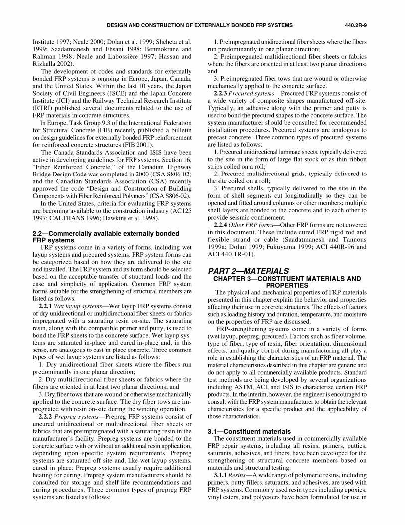
DESIGN AND CONSTRUCTION OF EXTERNALLY BONDED FRP SYSTEMS 440.2R-9
Institute 1997; Neale 2000; Dolan et al. 1999; Sheheta et al.1999; Saadatmanesh and Ehsani 1998; Benmokrane andRahman 1998; Neale and Labossière 1997; Hassan andRizkalla 2002).
The development of codes and standards for externallybonded FRP systems is ongoing in Europe, Japan, Canada,and the United States. Within the last 10 years, the JapanSociety of Civil Engineers (JSCE) and the Japan ConcreteInstitute (JCI) and the Railway Technical Research Institute(RTRI) published several documents related to the use ofFRP materials in concrete structures.
In Europe, Task Group 9.3 of the International Federationfor Structural Concrete (FIB) recently published a bulletinon design guidelines for externally bonded FRP reinforcementfor reinforced concrete structures (FIB 2001).
The Canada Standards Association and ISIS have beenactive in developing guidelines for FRP systems. Section 16,“Fiber Reinforced Concrete,” of the Canadian HighwayBridge Design Code was completed in 2000 (CSA S806-02)and the Canadian Standards Association (CSA) recentlyapproved the code “Design and Construction of BuildingComponents with Fiber Reinforced Polymers” (CSA S806-02).
In the United States, criteria for evaluating FRP systemsare becoming available to the construction industry (AC1251997; CALTRANS 1996; Hawkins et al. 1998).
2.2—Commercially available externally bonded FRP systems
FRP systems come in a variety of forms, including wetlayup systems and precured systems. FRP system forms canbe categorized based on how they are delivered to the siteand installed. The FRP system and its form should be selectedbased on the acceptable transfer of structural loads and theease and simplicity of application. Common FRP systemforms suitable for the strengthening of structural members arelisted as follows:
2.2.1 Wet layup systems—Wet layup FRP systems consistof dry unidirectional or multidirectional fiber sheets or fabricsimpregnated with a saturating resin on-site. The saturatingresin, along with the compatible primer and putty, is used tobond the FRP sheets to the concrete surface. Wet layup sys-tems are saturated in-place and cured in-place and, in thissense, are analogous to cast-in-place concrete. Three commontypes of wet layup systems are listed as follows:
1. Dry unidirectional fiber sheets where the fibers runpredominantly in one planar direction;
2. Dry multidirectional fiber sheets or fabrics where thefibers are oriented in at least two planar directions; and
3. Dry fiber tows that are wound or otherwise mechanicallyapplied to the concrete surface. The dry fiber tows are im-pregnated with resin on-site during the winding operation.
2.2.2 Prepreg systems—Prepreg FRP systems consist ofuncured unidirectional or multidirectional fiber sheets orfabrics that are preimpregnated with a saturating resin in themanufacturer’s facility. Prepreg systems are bonded to theconcrete surface with or without an additional resin application,depending upon specific system requirements. Prepregsystems are saturated off-site and, like wet layup systems,cured in place. Prepreg systems usually require additionalheating for curing. Prepreg system manufacturers should beconsulted for storage and shelf-life recommendations andcuring procedures. Three common types of prepreg FRPsystems are listed as follows:
1. Preimpregnated unidirectional fiber sheets where the fibersrun predominantly in one planar direction;
2. Preimpregnated multidirectional fiber sheets or fabricswhere the fibers are oriented in at least two planar directions;and
3. Preimpregnated fiber tows that are wound or otherwisemechanically applied to the concrete surface.
2.2.3 Precured systems—Precured FRP systems consist ofa wide variety of composite shapes manufactured off-site.Typically, an adhesive along with the primer and putty isused to bond the precured shapes to the concrete surface. Thesystem manufacturer should be consulted for recommendedinstallation procedures. Precured systems are analogous toprecast concrete. Three common types of precured systemsare listed as follows:
1. Precured unidirectional laminate sheets, typically deliveredto the site in the form of large flat stock or as thin ribbonstrips coiled on a roll;
2. Precured multidirectional grids, typically delivered tothe site coiled on a roll;
3. Precured shells, typically delivered to the site in theform of shell segments cut longitudinally so they can beopened and fitted around columns or other members; multipleshell layers are bonded to the concrete and to each other toprovide seismic confinement.
2.2.4 Other FRP forms—Other FRP forms are not coveredin this document. These include cured FRP rigid rod andflexible strand or cable (Saadatmanesh and Tannous1999a; Dolan 1999; Fukuyama 1999; ACI 440R-96 andACI 440.1R-01).
PART 2—MATERIALSCHAPTER 3—CONSTITUENT MATERIALS AND
PROPERTIES The physical and mechanical properties of FRP materials
presented in this chapter explain the behavior and propertiesaffecting their use in concrete structures. The effects of factorssuch as loading history and duration, temperature, and moistureon the properties of FRP are discussed.
FRP-strengthening systems come in a variety of forms(wet layup, prepreg, precured). Factors such as fiber volume,type of fiber, type of resin, fiber orientation, dimensionaleffects, and quality control during manufacturing all play arole in establishing the characteristics of an FRP material. Thematerial characteristics described in this chapter are generic anddo not apply to all commercially available products. Standardtest methods are being developed by several organizationsincluding ASTM, ACI, and ISIS to characterize certain FRPproducts. In the interim, however, the engineer is encouraged toconsult with the FRP system manufacturer to obtain the relevantcharacteristics for a specific product and the applicability ofthose characteristics.
3.1—Constituent materialsThe constituent materials used in commercially available
FRP repair systems, including all resins, primers, putties,saturants, adhesives, and fibers, have been developed for thestrengthening of structural concrete members based onmaterials and structural testing.
3.1.1 Resins—A wide range of polymeric resins, includingprimers, putty fillers, saturants, and adhesives, are used withFRP systems. Commonly used resin types including epoxies,vinyl esters, and polyesters have been formulated for use in
440.2R-10 ACI COMMITTEE REPORT
a wide range of environmental conditions. FRP systemmanufacturers use resins that have the following characteristics:• Compatibility with and adhesion to the concrete substrate;• Compatibility with and adhesion to the FRP composite
system;• Resistance to environmental effects, including but not
limited to moisture, salt water, temperature extremes, andchemicals normally associated with exposed concrete;
• Filling ability;• Workability;• Pot life consistent with the application;• Compatibility with and adhesion to the reinforcing
fiber; and• Development of appropriate mechanical properties for
the FRP composite.3.1.1.1 Primer—The primer is used to penetrate the
surface of the concrete, providing an improved adhesivebond for the saturating resin or adhesive.
3.1.1.2 Putty fillers—The putty is used to fill small surfacevoids in the substrate, such as bug holes, and to provide asmooth surface to which the FRP system can bond. Filledsurface voids also prevent bubbles from forming duringcuring of the saturating resin.
3.1.1.3 Saturating resin—The saturating resin is used toimpregnate the reinforcing fibers, fix them in place, andprovide a shear load path to effectively transfer load betweenfibers. The saturating resin also serves as the adhesive forwet layup systems, providing a shear load path between thepreviously primed concrete substrate and the FRP system.
3.1.1.4 Adhesives—Adhesives are used to bond precuredFRP laminate systems to the concrete substrate. The adhesiveprovides a shear load path between the concrete substrate andthe FRP reinforcing laminate. Adhesives are also used to bondtogether multiple layers of precured FRP laminates.
3.1.1.5 Protective coatings—The protective coating isused to protect the bonded FRP reinforcement from potentiallydamaging environmental effects. Coatings are typicallyapplied to the exterior surface of the cured FRP system afterthe adhesive or saturating resin has cured.
3.1.2 Fibers—Continuous glass, aramid, and carbon fibersare common reinforcements used with FRP systems. The fibersgive the FRP system its strength and stiffness. Typical ranges ofthe tensile properties of fibers are given in Appendix A. A moredetailed description of fibers is given in ACI 440R.
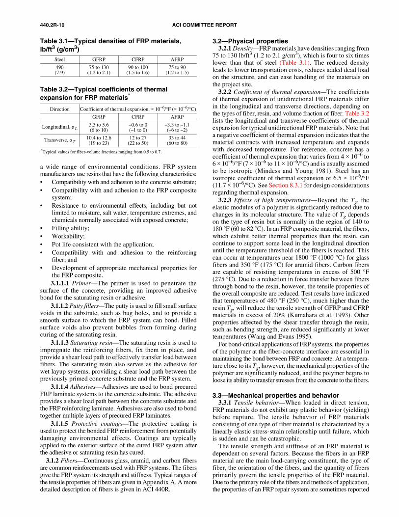
3.2—Physical properties3.2.1 Density—FRP materials have densities ranging from
75 to 130 lb/ft3 (1.2 to 2.1 g/cm3), which is four to six timeslower than that of steel (Table 3.1). The reduced densityleads to lower transportation costs, reduces added dead loadon the structure, and can ease handling of the materials onthe project site.
3.2.2 Coefficient of thermal expansion—The coefficientsof thermal expansion of unidirectional FRP materials differin the longitudinal and transverse directions, depending onthe types of fiber, resin, and volume fraction of fiber. Table 3.2lists the longitudinal and transverse coefficients of thermalexpansion for typical unidirectional FRP materials. Note thata negative coefficient of thermal expansion indicates that thematerial contracts with increased temperature and expandswith decreased temperature. For reference, concrete has acoefficient of thermal expansion that varies from 4 × 10⁻⁶ to6 × 10–6/°F (7 × 10⁻⁶ to 11 × 10–6/°C) and is usually assumedto be isotropic (Mindess and Young 1981). Steel has anisotropic coefficient of thermal expansion of 6.5 × 10⁻⁶/°F(11.7 × 10–6/°C). See Section 8.3.1 for design considerationsregarding thermal expansion.
3.2.3 Effects of high temperatures—Beyond the Tg, theelastic modulus of a polymer is significantly reduced due tochanges in its molecular structure. The value of Tg dependson the type of resin but is normally in the region of 140 to180 °F (60 to 82 °C). In an FRP composite material, the fibers,which exhibit better thermal properties than the resin, cancontinue to support some load in the longitudinal directionuntil the temperature threshold of the fibers is reached. Thiscan occur at temperatures near 1800 °F (1000 °C) for glassfibers and 350 °F (175 °C) for aramid fibers. Carbon fibersare capable of resisting temperatures in excess of 500 °F(275 °C). Due to a reduction in force transfer between fibersthrough bond to the resin, however, the tensile properties ofthe overall composite are reduced. Test results have indicatedthat temperatures of 480 °F (250 °C), much higher than theresin Tg, will reduce the tensile strength of GFRP and CFRPmaterials in excess of 20% (Kumahara et al. 1993). Otherproperties affected by the shear transfer through the resin,such as bending strength, are reduced significantly at lowertemperatures (Wang and Evans 1995).
For bond-critical applications of FRP systems, the propertiesof the polymer at the fiber-concrete interface are essential inmaintaining the bond between FRP and concrete. At a tempera-ture close to its Tg, however, the mechanical properties of thepolymer are significantly reduced, and the polymer begins toloose its ability to transfer stresses from the concrete to the fibers.
3.3—Mechanical properties and behavior3.3.1 Tensile behavior—When loaded in direct tension,
FRP materials do not exhibit any plastic behavior (yielding)before rupture. The tensile behavior of FRP materialsconsisting of one type of fiber material is characterized by alinearly elastic stress-strain relationship until failure, whichis sudden and can be catastrophic.
The tensile strength and stiffness of an FRP material isdependent on several factors. Because the fibers in an FRPmaterial are the main load-carrying constituent, the type offiber, the orientation of the fibers, and the quantity of fibersprimarily govern the tensile properties of the FRP material.Due to the primary role of the fibers and methods of application,the properties of an FRP repair system are sometimes reported
Table 3.1—Typical densities of FRP materials,lb/ft3 (g/cm3)
Steel GFRP CFRP AFRP
490(7.9)
75 to 130(1.2 to 2.1)
90 to 100(1.5 to 1.6)
75 to 90(1.2 to 1.5)
Table 3.2—Typical coefficients of thermal expansion for FRP materials*
Direction Coefficient of thermal expansion, × 10–6/°F (× 10–6/°C)
GFRP CFRP AFRP
Longitudinal, αL3.3 to 5.6(6 to 10)
–0.6 to 0(–1 to 0)
–3.3 to –1.1(–6 to –2)
Transverse, αT10.4 to 12.6(19 to 23)
12 to 27(22 to 50)
33 to 44(60 to 80)
*Typical values for fiber-volume fractions ranging from 0.5 to 0.7.
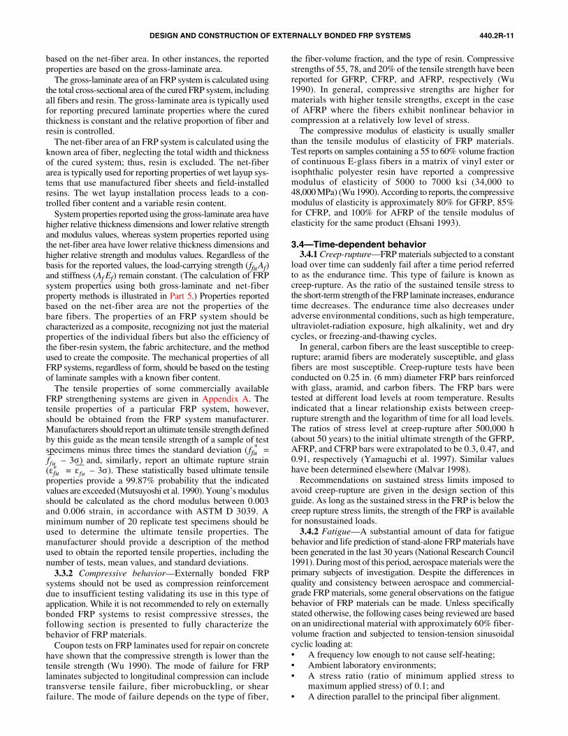
DESIGN AND CONSTRUCTION OF EXTERNALLY BONDED FRP SYSTEMS 440.2R-11
based on the net-fiber area. In other instances, the reportedproperties are based on the gross-laminate area.
The gross-laminate area of an FRP system is calculated usingthe total cross-sectional area of the cured FRP system, includingall fibers and resin. The gross-laminate area is typically usedfor reporting precured laminate properties where the curedthickness is constant and the relative proportion of fiber andresin is controlled.
The net-fiber area of an FRP system is calculated using theknown area of fiber, neglecting the total width and thicknessof the cured system; thus, resin is excluded. The net-fiberarea is typically used for reporting properties of wet layup sys-tems that use manufactured fiber sheets and field-installedresins. The wet layup installation process leads to a con-trolled fiber content and a variable resin content.
System properties reported using the gross-laminate area havehigher relative thickness dimensions and lower relative strengthand modulus values, whereas system properties reported usingthe net-fiber area have lower relative thickness dimensions andhigher relative strength and modulus values. Regardless of thebasis for the reported values, the load-carrying strength (ffu Af)and stiffness (Af Ef) remain constant. (The calculation of FRPsystem properties using both gross-laminate and net-fiberproperty methods is illustrated in Part 5.) Properties reportedbased on the net-fiber area are not the properties of thebare fibers. The properties of an FRP system should becharacterized as a composite, recognizing not just the materialproperties of the individual fibers but also the efficiency ofthe fiber-resin system, the fabric architecture, and the methodused to create the composite. The mechanical properties of allFRP systems, regardless of form, should be based on the testingof laminate samples with a known fiber content.
The tensile properties of some commercially availableFRP strengthening systems are given in Appendix A. Thetensile properties of a particular FRP system, however,should be obtained from the FRP system manufacturer.Manufacturers should report an ultimate tensile strength definedby this guide as the mean tensile strength of a sample of testspecimens minus three times the standard deviation ( ffu
* = – 3σ) and, similarly, report an ultimate rupture strain
(εfu* = – 3σ). These statistically based ultimate tensile
properties provide a 99.87% probability that the indicatedvalues are exceeded (Mutsuyoshi et al. 1990). Young’s modulusshould be calculated as the chord modulus between 0.003and 0.006 strain, in accordance with ASTM D 3039. Aminimum number of 20 replicate test specimens should beused to determine the ultimate tensile properties. Themanufacturer should provide a description of the methodused to obtain the reported tensile properties, including thenumber of tests, mean values, and standard deviations.
3.3.2 Compressive behavior—Externally bonded FRPsystems should not be used as compression reinforcementdue to insufficient testing validating its use in this type ofapplication. While it is not recommended to rely on externallybonded FRP systems to resist compressive stresses, thefollowing section is presented to fully characterize thebehavior of FRP materials.
Coupon tests on FRP laminates used for repair on concretehave shown that the compressive strength is lower than thetensile strength (Wu 1990). The mode of failure for FRPlaminates subjected to longitudinal compression can includetransverse tensile failure, fiber microbuckling, or shearfailure. The mode of failure depends on the type of fiber,
the fiber-volume fraction, and the type of resin. Compressivestrengths of 55, 78, and 20% of the tensile strength have beenreported for GFRP, CFRP, and AFRP, respectively (Wu1990). In general, compressive strengths are higher formaterials with higher tensile strengths, except in the caseof AFRP where the fibers exhibit nonlinear behavior incompression at a relatively low level of stress.
The compressive modulus of elasticity is usually smallerthan the tensile modulus of elasticity of FRP materials.Test reports on samples containing a 55 to 60% volume fractionof continuous E-glass fibers in a matrix of vinyl ester orisophthalic polyester resin have reported a compressivemodulus of elasticity of 5000 to 7000 ksi (34,000 to48,000 MPa) (Wu 1990). According to reports, the compressivemodulus of elasticity is approximately 80% for GFRP, 85%for CFRP, and 100% for AFRP of the tensile modulus ofelasticity for the same product (Ehsani 1993).
3.4—Time-dependent behavior3.4.1 Creep-rupture—FRP materials subjected to a constant
load over time can suddenly fail after a time period referredto as the endurance time. This type of failure is known ascreep-rupture. As the ratio of the sustained tensile stress tothe short-term strength of the FRP laminate increases, endurancetime decreases. The endurance time also decreases underadverse environmental conditions, such as high temperature,ultraviolet-radiation exposure, high alkalinity, wet and drycycles, or freezing-and-thawing cycles.
In general, carbon fibers are the least susceptible to creep-rupture; aramid fibers are moderately susceptible, and glassfibers are most susceptible. Creep-rupture tests have beenconducted on 0.25 in. (6 mm) diameter FRP bars reinforcedwith glass, aramid, and carbon fibers. The FRP bars weretested at different load levels at room temperature. Resultsindicated that a linear relationship exists between creep-rupture strength and the logarithm of time for all load levels.The ratios of stress level at creep-rupture after 500,000 h(about 50 years) to the initial ultimate strength of the GFRP,AFRP, and CFRP bars were extrapolated to be 0.3, 0.47, and0.91, respectively (Yamaguchi et al. 1997). Similar valueshave been determined elsewhere (Malvar 1998).
Recommendations on sustained stress limits imposed toavoid creep-rupture are given in the design section of thisguide. As long as the sustained stress in the FRP is below thecreep rupture stress limits, the strength of the FRP is availablefor nonsustained loads.
3.4.2 Fatigue—A substantial amount of data for fatiguebehavior and life prediction of stand-alone FRP materials havebeen generated in the last 30 years (National Research Council1991). During most of this period, aerospace materials were theprimary subjects of investigation. Despite the differences inquality and consistency between aerospace and commercial-grade FRP materials, some general observations on the fatiguebehavior of FRP materials can be made. Unless specificallystated otherwise, the following cases being reviewed are basedon an unidirectional material with approximately 60% fiber-volume fraction and subjected to tension-tension sinusoidalcyclic loading at:• A frequency low enough to not cause self-heating; • Ambient laboratory environments; • A stress ratio (ratio of minimum applied stress to
maximum applied stress) of 0.1; and • A direction parallel to the principal fiber alignment.
ffuεfu
440.2R-12 ACI COMMITTEE REPORT
Test conditions that raise the temperature and moisturecontent of FRP materials generally degrade the ambientenvironment fatigue behavior.
Of all types of FRP composites for infrastructure applications,CFRP is the least prone to fatigue failure. An endurance limitof 60 to 70% of the initial static ultimate strength of CFRP istypical. On a plot of stress versus the logarithm of the number ofcycles at failure (S-N curve), the downward slope of CFRPis usually about 5% of the initial static ultimate strength perdecade of logarithmic life. At one million cycles, the fatiguestrength is generally between 60 and 70% of the initial staticultimate strength and is relatively unaffected by the moistureand temperature exposures of concrete structures unless theresin or fiber/resin interface is substantially degraded by theenvironment.
In ambient-environment laboratory tests (Mandell andMeier 1983), individual glass fibers demonstrated delayedrupture caused by stress corrosion, which had been inducedby the growth of surface flaws in the presence of even minutequantities of moisture. When many glass fibers are embeddedinto a matrix to form an FRP composite, a cyclic tensilefatigue effect of approximately 10% loss in the initial staticstrength per decade of logarithmic lifetime is observed(Mandell 1982). This fatigue effect is thought to be due to fiber-fiber interactions and not dependent on the stress corrosionmechanism described for individual fibers. Usually, noclear fatigue limit can be defined. Environmental factorscan play an important role in the fatigue behavior of glassfibers due to their susceptibility to moisture, alkaline,and acidic solutions.
Aramid fibers, for which substantial durability data areavailable, appear to behave reasonably well in fatigue.Neglecting in this context the rather poor durability of allaramid fibers in compression, the tension-tension fatiguebehavior of an impregnated aramid fiber strand is excellent.Strength degradation per decade of logarithmic lifetime isapproximately 5 to 6% (Roylance and Roylance 1981).While no distinct endurance limit is known for AFRP, two-million-cycle endurance limits of commercial AFRP tendonsfor concrete applications have been reported in the range of54 to 73% of the ultimate tensile strength (Odagiri et al.1997). Based on these findings, Odagiri suggested that themaximum stress be set to 0.54 to 0.73 times the tensilestrength. Because the slope of the applied stress versuslogarithmic endurance time of AFRP is similar to the slopeof the stress versus logarithmic cyclic lifetime data, theindividual fibers appear to fail by a strain-limited, creep-rupture process. This lifetime-limiting mechanism incommercial AFRP bars is accelerated by exposure to moistureand elevated temperature (Roylance and Roylance 1981;Rostasy 1997).
3.5—DurabilityMany FRP systems exhibit reduced mechanical properties
after exposure to certain environmental factors, includingtemperature, humidity, and chemical exposure. The exposureenvironment, duration of the exposure, resin type andformulation, fiber type, and resin-curing method aresome of the factors that influence the extent of the reduction inmechanical properties. These factors are discussed in moredetail in Section 8.3. The tensile properties reported by themanufacturer are based on testing conducted in a laboratoryenvironment and do not reflect the effects of environmental
exposure. These properties should be adjusted in accordancewith Section 8.4 to account for the anticipated service environ-ment to which the FRP system may be exposed during itsservice life.
3.6—FRP system qualificationFRP systems should be qualified for use on a project on the
basis of independent laboratory test data of the FRP-constituentmaterials and the laminates made with them, structural testdata for the type of application being considered, and durabilitydata representative of the anticipated environment. Test dataprovided by the FRP system manufacturer demonstrating theproposed FRP system meets all mechanical and physicaldesign requirements including tensile strength, durability,resistance to creep, bond to substrate, and Tg should beconsidered but not used as the sole basis for qualification.
FRP composite systems that have not been fully testedshould not be considered for use. Mechanical propertiesof FRP systems should be determined from tests on laminatesmanufactured in a process representative of their field installa-tion. Mechanical properties should be tested in generalconformance with the procedures listed in Appendix B.Modifications of standard testing procedures may be permittedto emulate field assemblies.
The specified material-qualification programs shouldrequire sufficient laboratory testing to measure the repeatabilityand reliability of critical properties. Testing of multiplebatches of FRP materials is recommended. Independentstructural testing can be used to evaluate a system’s performancefor the specific application.
PART 3—RECOMMENDED CONSTRUCTION REQUIREMENTS
CHAPTER 4—SHIPPING, STORAGE, AND HANDLING
4.1—ShippingFRP system constituent materials must be packaged and
shipped in a manner that conforms to all applicable federaland state packaging and shipping codes and regulations.Packaging, labeling, and shipping for thermosetting resinmaterials are controlled by CFR 49. Many materials areclassified as corrosive, flammable, or poisonous in subchapter C(CFR 49) under “Hazardous Materials Regulations.”
4.2—Storage4.2.1 Storage conditions—To preserve the properties and
maintain safety in the storage of FRP system constituentmaterials, the materials should be stored in accordance withthe manufacturer’s recommendations. Certain constituentmaterials, such as reactive curing agents, hardeners, initiators,catalysts, and cleaning solvents, have safety-related require-ments and should be stored in a manner as recommended bythe manufacturer and OSHA. Catalysts and initiators (usuallyperoxides) should be stored separately.
4.2.2 Shelf life—The properties of the uncured resincomponents can change with time, temperature, or humidity.Such conditions can affect the reactivity of the mixed systemand the uncured and cured properties. The manufacturer setsa recommended shelf life within which the properties of theresin-based materials should continue to meet or exceedstated performance criteria. Any component material thathas exceeded its shelf life, has deteriorated, or has beencontaminated should not be used. FRP materials deemed
DESIGN AND CONSTRUCTION OF EXTERNALLY BONDED FRP SYSTEMS 440.2R-13
unusable should be disposed of in a manner specified by themanufacturer and acceptable to state and federal environmentalcontrol regulations.
4.3—Handling4.3.1 Material safety data sheets—Material safety data
sheets (MSDS) for all FRP constituent materials andcomponents must be obtained from the manufacturers andmust be accessible at the job site.
4.3.2 Information sources—Detailed information on thehandling and potential hazards of FRP constituent materialscan be found in information sources, such as ACI and ICRIreports, company literature and guides, OSHA guidelines,and other government informational documents. ACI 503Ris specifically noted as a general guideline for the safe handlingof epoxy compounds.
4.3.3 General handling hazards—Thermosetting resinsdescribe a generic family of products that includes unsaturatedpolyesters, vinyl esters, epoxy, and polyurethane resins. Thematerials used with them are generally described as hardeners,curing agents, peroxide initiators, isocyanates, fillers, andflexibilizers. There are precautions that should be observedwhen handling thermosetting resins and their componentmaterials. Some general hazards that may be encounteredwhen handling thermosetting resins are listed as follows:• Skin irritation, such as burns, rashes, and itching;• Skin sensitization, which is an allergic reaction similar
to that caused by poison ivy, building insulation, orother allergens;
• Breathing organic vapors from cleaning solvents,monomers, and diluents;
• With a sufficient concentration in air, explosion or fireof flammable materials when exposed to heat, flames,pilot lights, sparks, static electricity, cigarettes, or othersources of ignition;
• Exothermic reactions of mixtures of materials causingfires or personal injury; and
• Nuisance dust caused by grinding or handling of thecured FRP materials (consult manufacturer’s literaturefor specific hazards).
The complexity of thermosetting resins and associatedmaterials makes it essential that labels and MSDS are read andunderstood by those working with these products. CFR 16, Part1500, regulates the labeling of hazardous substances andincludes thermosetting-resin materials. ANSI Z-129.1 providesfurther guidance regarding classification and precautions.
4.3.4 Personnel safe handling and clothing—Disposablesuits and gloves are suitable for handling fiber and resinmaterials. Disposable rubber or plastic gloves are recommendedand should be discarded after each use. Gloves should beresistant to resins and solvents.
Safety glasses or goggles should be used when handlingresin components and solvents. Respiratory protection, suchas dust masks or respirators, should be used when fiber fly,dust, or organic vapors are present, or during mixing andplacing of resins if required by the FRP system manufacturer.
4.3.5 Workplace safe handling—The workplace should bewell ventilated. Surfaces should be covered as needed toprotect against contamination and resin spills. Each FRPsystem constituent material has different handling andstorage requirements to prevent damage. Consult with thematerial manufacturer for guidance. Some resin systems arepotentially dangerous during the mixing of the components.
Consult the manufacturer’s literature for proper mixingprocedures and MSDSs for specific handling hazards. Ambientcure resin formulations produce heat when curing, which inturn accelerates the reaction. Uncontrolled reactions, includingfuming, fire, or violent boiling, may occur in containersholding a mixed mass of resin; therefore, containers shouldbe monitored.
4.3.6 Clean-up and disposal—Clean-up can involve useof flammable solvents, and appropriate precautionsshould be observed. Clean-up solvents are available that donot present the same flammability concerns. All waste materialsshould be contained and disposed of as prescribed by the prevail-ing environmental authority.
CHAPTER 5—INSTALLATIONProcedures for installing FRP systems have been developed
by the system manufacturers and often differ between systems.In addition, installation procedures can vary within a system,depending on the type and condition of the structure. Thischapter presents general guidelines for the installation of FRPsystems. Contractors trained in accordance with the installationprocedures developed by the system manufacturer shouldinstall FRP systems. Deviations from the procedures developedby the FRP system manufacturer should not be allowed withoutconsulting with the manufacturer.
5.1—Contractor competencyThe FRP system installation contractor should demonstrate
competency for surface preparation and application of the FRPsystem to be installed. Contractor competency can be demon-strated by providing evidence of training and documentation ofrelated work previously completed by the contractor or by actualsurface preparation and installation of the FRP system onportions of the structure. The FRP system manufacturer or theirauthorized agent should train the contractor’s applicationpersonnel in the installation procedures of their system andensure they are competent to install the system.
5.2—Temperature, humidity, and moisture considerations
Temperature, relative humidity, and surface moisture atthe time of installation can affect the performance of the FRPsystem. Conditions to be observed before and during installationinclude surface temperature of the concrete, air temperature,relative humidity, and corresponding dew point.
Primers, saturating resins, and adhesives generally shouldnot be applied to cold or frozen surfaces. When the surfacetemperature of the concrete surface falls below a minimumlevel as specified by the FRP system manufacturer, impropersaturation of the fibers and improper curing of the resinconstituent materials can occur, compromising the integrityof the FRP system. An auxiliary heat source can be used toraise the ambient and surface temperature during installation.The heat source should be clean and not contaminate the surfaceor the uncured FRP system.
Resins and adhesives generally should not be applied todamp or wet surfaces unless they have been formulated forsuch applications. FRP systems should not be applied to concretesurfaces that are subject to moisture vapor transmission. Thetransmission of moisture vapor from a concrete surfacethrough the uncured resin materials typically appears assurface bubbles and can compromise the bond between theFRP system and the substrate.
440.2R-14 ACI COMMITTEE REPORT
5.3—EquipmentEach FRP system has unique equipment designed specifically
for the application of the materials for that system. Thisequipment can include resin impregnators, sprayers, lifting/positioning devices, and winding machines. All equipmentshould be clean and in good operating condition. Thecontractor should have personnel trained in the operation ofall equipment. Personal protective equipment, such asgloves, masks, eye guards, and coveralls, should be chosenand worn for each employee’s function. All supplies andequipment should be available in sufficient quantities to allowcontinuity in the installation project and quality assurance.
5.4—Substrate repair and surface preparationThe behavior of concrete members strengthened or retrofitted
with FRP systems is highly dependent on a sound concretesubstrate and proper preparation and profiling of the concretesurface. An improperly prepared surface can result in debondingor delamination of the FRP system before achieving the designload transfer. The general guidelines presented in this chaptershould be applicable to all externally bonded FRP systems.Specific guidelines for a particular FRP system should beobtained from the FRP system manufacturer. Substratepreparation can generate noise, dust, and disruption to buildingoccupants.
5.4.1 Substrate repair—All problems associated with thecondition of the original concrete and the concrete substratethat can compromise the integrity of the FRP system shouldbe addressed before surface preparation begins. ACI 546R andICRI 03730 detail methods for the repair and surface preparationof concrete. All concrete repairs should meet the requirementsof the design drawings and project specifications. The FRPsystem manufacturer should be consulted on the compatibilityof the materials used for repairing the substrate with the FRPsystem.
5.4.1.1 Corrosion-related deterioration—Externallybonded FRP systems should not be applied to concretesubstrates suspected of containing corroded reinforcingsteel. The expansive forces associated with the corrosionprocess are difficult to determine and could compromise thestructural integrity of the externally applied FRP system.The cause(s) of the corrosion should be addressed and thecorrosion-related deterioration should be repaired before theapplication of any externally bonded FRP system.
5.4.1.2 Injection of cracks—Some FRP manufacturershave reported that the movement of cracks 0.010 in. (0.3 mm)and wider can affect the performance of the externally bondedFRP system through delamination or fiber crushing. Con-sequently, cracks wider than 0.010 in. (0.3 mm) should bepressure injected with epoxy in accordance with ACI 224.1R.Smaller cracks exposed to aggressive environments may requireresin injection or sealing to prevent corrosion of existingsteel reinforcement. Crack-width criteria for various exposureconditions are given in ACI 224R.
5.4.2 Surface preparation—Surface preparation requirementsshould be based on the intended application of the FRP system.Applications can be categorized as bond-critical or contact-critical. Bond-critical applications, such as flexural or shearstrengthening of beams, slabs, columns, or walls, require anadhesive bond between the FRP system and the concrete.Contact-critical applications, such as confinement of columns,only require intimate contact between the FRP system andthe concrete. Contact-critical applications do not require an
adhesive bond between the FRP system and the concretesubstrate, although one is often provided to facilitate installation.
5.4.2.1 Bond-critical applications—Surface preparationfor bond-critical applications should be in accordance withrecommendations of ACI 546R and ICRI 03730. Theconcrete or repaired surfaces to which the FRP system is tobe applied should be freshly exposed and free of loose orunsound materials. Where fibers wrap around the corners ofrectangular cross sections, the corners should be rounded toa minimum 1/2 in. (13 mm) radius to prevent stress concentra-tions in the FRP system and voids between the FRP systemand the concrete. Roughened corners should be smoothedwith putty. Obstructions, reentrant corners, concave surfaces,and embedded objects can affect the performance of the FRPsystem and should be addressed. Obstructions and embeddedobjects may need to be removed before installing the FRPsystem. Reentrant corners and concave surfaces may requirespecial detailing to ensure that the bond of the FRP system to thesubstrate is maintained. Surface preparation can be accom-plished using abrasive or water-blasting techniques. All laitance,dust, dirt, oil, curing compound, existing coatings, and any othermatter that could interfere with the bond of the FRP system tothe concrete should be removed. Bug holes and other smallsurface voids should be completely exposed during surfaceprofiling. After the profiling operations are complete, thesurface should be cleaned and protected before FRP installationso that no materials that can interfere with bond are redepositedon the surface.
The concrete surface should be prepared to a minimumconcrete surface profile (CSP) 3 as defined by the ICRI-surface-profile chips. The FRP system manufacturer shouldbe consulted to determine if more aggressive surface profilingis necessary. Localized out-of-plane variations, includingform lines, should not exceed 1/32 in. (1 mm) or the tolerancesrecommended by the FRP system manufacturer. Localizedout-of-plane variations can be removed by grinding beforeabrasive or water blasting or can be smoothed over using epoxyputty if the variations are very small. Bug holes and voidsshould be filled with epoxy putty.
All surfaces to receive the strengthening system should beas dry as recommended by the FRP system manufacturer.Water in the pores can inhibit resin penetration and reducemechanical interlocking. Moisture content should beevaluated in accordance with the requirements of ACI 503.4.
5.4.2.2 Contact-critical applications—In applicationsinvolving confinement of structural concrete members,surface preparation should promote continuous intimatecontact between the concrete surface and the FRP system.Surfaces to be wrapped should, at a minimum, be flat orconvex to promote proper loading of the FRP system. Largevoids in the surface should be patched with a repair materialcompatible with the existing concrete.
Materials with low compressive strength and elastic modulus,like plaster, can reduce the effectiveness of the FRP systemand should be removed.
5.5—Mixing of resinsMixing of resins should be done in accordance with the FRP
system manufacturer’s recommended procedure. All resincomponents should be at a proper temperature and mixed in thecorrect ratio until there is a uniform and complete mixing ofcomponents. Resin components are often contrasting colors, sofull mixing is achieved when color streaks are eliminated.
DESIGN AND CONSTRUCTION OF EXTERNALLY BONDED FRP SYSTEMS 440.2R-15
Resins should be mixed for the prescribed mixing time andvisually inspected for uniformity of color. The materialmanufacturer should supply recommended batch sizes, mixtureratios, mixing methods, and mixing times.
Mixing equipment can include small electrically poweredmixing blades or specialty units, or resins can be mixed byhand stirring, if needed. Resin mixing should be in quantitiessufficiently small to ensure that all mixed resin can be usedwithin the resin’s pot life. Mixed resin that exceeds its potlife should not be used because the viscosity will continue toincrease and will adversely affect the resin’s ability topenetrate the surface or saturate the fiber sheet.
5.6—Application of constituent materialsFumes can accompany the application of some FRP resins.
FRP systems should be selected with consideration for theirimpact on the environment, including emission of volatileorganic compounds and toxicology.
5.6.1 Primer and putty—Where required, primer shouldbe applied to all areas on the concrete surface where the FRPsystem is to be placed. The primer should be placed uniformlyon the prepared surface at the manufacturer’s specified rateof coverage. The applied primer should be protected fromdust, moisture, and other contaminants prior to applying theFRP system.
Putty should be used in an appropriate thickness andsequence with the primer as recommended by the FRPmanufacturer. The system-compatible putty, which is typicallya thickened epoxy paste, should be used only to fill voids andsmooth surface discontinuities before the application of othermaterials. Rough edges or trowel lines of cured putty shouldbe ground smooth before continuing the installation.
Prior to applying the saturating resin or adhesive, the primerand putty should be allowed to cure as specified by the FRPsystem manufacturer. If the putty and primer are fully cured,additional surface preparation may be required prior to theapplication of the saturating resin or adhesive. Surfacepreparation requirements should be obtained from the FRPsystem manufacturer.
5.6.2 Wet layup systems—Wet layup FRP systems aretypically installed by hand using dry fiber sheets and asaturating resin, and the manufacturer’s recommendationsshould be followed. The saturating resin should be applieduniformly to all prepared surfaces where the system is to beplaced. The fibers can also be impregnated in a separate processusing a resin-impregnating machine before placement on theconcrete surface.
The reinforcing fibers should be gently pressed into theuncured saturating resin in a manner recommended by theFRP system manufacturer. Entrapped air between layersshould be released or rolled out before the resin sets. Sufficientsaturating resin should be applied to achieve full saturation ofthe fibers.
Successive layers of saturating resin and fiber materialsshould be placed before the complete cure of the previouslayer of resin. If previous layers are cured, interlayer surfacepreparation, such as light sanding or solvent application asrecommended by the system manufacturer, may be required.
5.6.3 Machine-applied systems—Machine-applied systemscan use resin-preimpregnated tow or dry-fiber tows. Prepregtows are impregnated with saturating resin off-site anddelivered to the work site as spools of prepreg tow material.
Dry fibers are impregnated at the job site during the windingprocess.
Wrapping machines are primarily used for the automatedwrapping of concrete columns. The tows can be wound eitherhorizontally or at a specified angle. The wrapping machineis placed around the column and automatically wraps the towmaterial around the perimeter of the column while movingup and down the column.
After wrapping, prepreg systems should be cured at anelevated temperature. Usually a heat source is placed aroundthe column for a predetermined temperature and time schedulein accordance with the manufacturer’s recommendations.Temperatures are controlled to ensure consistent quality. Theresulting FRP jackets do not have any seams or welds becausethe tows are continuous. In all of the previous application steps,the FRP system manufacturer’s recommendations should befollowed.
5.6.4 Precured systems—Precured systems include shells,strips, and open grid forms that are typically installed with anadhesive. Adhesives should be uniformly applied to theprepared surfaces where precured systems are to be placed,except in certain instances of concrete confinement whereadhesion of the FRP system to the concrete substrate may notbe required.
Precured laminate surfaces to be bonded should be cleanand prepared in accordance with the manufacturer’s recommen-dation. The precured sheets or curved shells should be placedon or into the wet adhesive in a manner recommended by theFRP manufacturer. Entrapped air between layers shouldbe released or rolled out before the adhesive sets. Adhesiveshould be applied at a rate recommended by the FRPmanufacturer to ensure full bonding of successive layers.
5.6.5 Protective coatings—Coatings should be compatiblewith the FRP strengthening system and applied in accordancewith the manufacturer’s recommendations. Typically, theuse of solvents to clean the FRP surface prior to installingcoatings is not recommended due to the deleterious effectssolvents can have on the polymer resins. The FRP systemmanufacturer should approve any use of solvent-wipepreparation of FRP surfaces before the application ofprotective coatings.
The coatings should be periodically inspected andmaintenance should be provided to ensure the effectivenessof the coatings.
5.7—Alignment of FRP materialsThe FRP-ply orientation and ply-stacking sequence should
be specified. Small variations in angle, as little as 5 degrees,from the intended direction of fiber alignment can cause asubstantial reduction in strengthening. Deviations in plyorientation should only be made if approved by the engineer.
Sheet and fabric materials should be handled in a mannerto maintain the fiber straightness and orientation. Fabrickinks, folds, or other forms of severe waviness should bereported to the engineer.
5.8—Multiple plies and lap splicesMultiple plies can be used, provided all plies are fully
impregnated with the resin system, the resin shear strength issufficient to transfer the shearing load between plies, and thebond strength between the concrete and FRP system issufficient. For long spans, multiple lengths of fiber materialor precured stock can be used to continuously transfer the
440.2R-16 ACI COMMITTEE REPORT
load by providing adequate lap splices. Lap splices should bestaggered, unless noted otherwise by the engineer. Lap splicedetails, including lap length, should be based on testing andinstalled in accordance with the manufacturer’s recommen-dations. Due to the unique characteristics of some FRPsystems, multiple plies and lap splices are not always possible.Specific guidelines on lap splices are given in Chapter 12.
5.9—Curing of resinsCuring of resins is a time-temperature-dependent phenome-
non. Ambient-cure resins can take several days to reach fullcure. Temperature extremes or fluctuations can retard oraccelerate the resin curing time. The FRP system manufacturermay offer several prequalified grades of resin to accommodatethese situations.
Elevated cure systems require the resin to be heated to aspecific temperature for a specified period of time. Variouscombinations of time and temperature within a definedenvelope should provide full cure of the system.
All resins should be cured according to the manufacturer’srecommendation. Field modification of resin chemistry shouldnot be permitted.
Cure of installed plies should be monitored before placingsubsequent plies. Installation of successive layers should behalted if there is a curing anomaly.
5.10—Temporary protectionAdverse temperatures; direct contact by rain, dust, or dirt;
excessive sunlight; high humidity; or vandalism can damagean FRP system during installation and cause improper cureof the resins. Temporary protection, such as tents and plasticscreens, may be required during installation and until theresins have cured. If temporary shoring is required, the FRPsystem should be fully cured before removing the shoringand allowing the structural member to carry the design loads.In the event of suspected damage to the FRP system duringinstallation, the engineer should be notified and the FRPsystem manufacturer consulted.
CHAPTER 6—INSPECTION, EVALUATION, AND ACCEPTANCE
Quality-assurance and quality-control (QA/QC) programsand criteria are to be maintained by the FRP system manu-facturers, the installation contractors, and others associatedwith the project. The quality-control program should becomprehensive and cover all aspects of the strengtheningproject. The degree of quality control and the scope of testing,inspection, and record keeping depends on the size andcomplexity of the project.
Quality assurance is achieved through a set of inspections andapplicable tests to document the acceptability of the installation.Project specifications should include a requirement to providea quality-assurance plan for the installation and curing of allFRP materials. The plan should include personnel safetyissues, application and inspection of the FRP system, locationand placement of splices, curing provisions, means to ensuredry surfaces, quality-assurance samples, cleanup, and therequired submittals listed in Section 13.3.
6.1—InspectionFRP systems and all associated work should be inspected
as required by the applicable codes. In the absence of suchrequirements, inspection should be conducted by or under
the supervision of a licensed engineer or a qualified inspector.Inspectors should be knowledgeable of FRP systems and betrained in the installation of FRP systems. The qualifiedinspector should require compliance with the design drawingsand project specifications. During the installation of the FRPsystem, daily inspection should be conducted and shouldinclude:• Date and time of installation;• Ambient temperature, relative humidity, and general
weather observations; • Surface temperature of concrete;• Surface dryness per ACI 503.4;• Surface preparation methods and resulting profile using
the ICRI-surface-profile-chips;• Qualitative description of surface cleanliness;• Type of auxiliary heat source, if applicable;• Widths of cracks not injected with epoxy;• Fiber or precured laminate batch number(s) and
approximate location in structure;• Batch numbers, mixture ratios, mixing times, and
qualitative descriptions of the appearance of all mixedresins, including primers, putties, saturants, adhesives,and coatings mixed for the day;
• Observations of progress of cure of resins;• Conformance with installation procedures;• Pull-off test results: bond strength, failure mode, and
location;• FRP properties from tests of field sample panels or
witness panels, if required;• Location and size of any delaminations or air voids; and• General progress of work.
The inspector should provide the engineer or owner withthe inspection records and witness panels. It is recommendedthat the records and witness panels be retained for a minimum of10 years or a period specified by the engineer. The installationcontractor should retain sample cups of mixed resin andmaintain a record of the placement of each batch.
6.2—Evaluation and acceptanceFRP systems should be evaluated and accepted/rejected
based on conformance/nonconformance with the design draw-ings and specifications. FRP system material properties, instal-lation within specified placement tolerances, presence ofdelaminations, cure of resins, and adhesion to substrate shouldbe included in the evaluation. Placement tolerances including fi-ber orientation, cured thickness, ply orientation, width and spac-ing, corner radii, and lap splice lengths should be evaluated.
Witness panel and pulloff tests are used to evaluate theinstalled FRP system. In-place load testing can also be usedto confirm the installed behavior of the FRP strengthenedmember (Nanni and Gold 1998).
6.2.1 Materials—Before starting the project, the FRPsystem manufacturer should submit certification of specifiedmaterial properties and identification of all materials to beused. Additional material testing can be conducted if deemednecessary based on the complexity and intricacy of theproject. Evaluation of delivered FRP materials can includetests for tensile strength, infrared spectrum analysis, Tg, geltime, pot life, and adhesive shear strength. These tests areusually performed on material samples sent to a laboratory,according to the quality-control test plan. Tests for pot life ofresins and curing hardness are usually conducted on-site.
DESIGN AND CONSTRUCTION OF EXTERNALLY BONDED FRP SYSTEMS 440.2R-17
Materials that do not meet the minimum requirements asspecified by the engineer should be rejected.
Witness panels can be used to evaluate the tensile strengthand modulus, lap splice strength, hardness, and Tg of the FRPsystem installed and cured on-site using installation proce-dures similar to those used to install and cure the FRP system.During installation, flat panels of predetermined dimensionsand thickness can be fabricated on-site according to a prede-termined sampling plan. After curing on-site, the panels canthen be sent to a laboratory for testing. Witness panels can beretained or submitted to an approved laboratory in a timelymanner for testing of strength, hardness, and Tg. Strength andelastic modulus of FRP materials can be determined in accor-dance with ASTM D 3039 and ISIS (1998). The properties tobe evaluated by testing should be specified. The engineer maywaive or alter the frequency of testing.
Some FRP systems, including precured and machine-wound systems, do not lend themselves to the fabrication ofsmall, flat, witness panels. For these cases, the engineer canmodify the requirements to include test panels or samplesprovided by the manufacturer. Tension strength and elasticmodulus, lap-splice strength of FRP materials can also bedetermined using burst testing of field fabricated ringspecimens (ISIS 1998).
During installation, sample cups of mixed resin shouldbe prepared according to a predetermined sampling planand retained for testing to determine the level of cure (seeSection 6.2.4).
6.2.2 Fiber orientation—Fiber or precured-laminateorientation should be evaluated by visual inspection. Fiberwaviness—a localized appearance of fibers that deviate fromthe general straight-fiber line in the form of kinks orwaves—should be evaluated for wet layup systems.
Fiber or precured laminate misalignment of more than5 degrees from that specified on the design drawings (approxi-mately 1 in./ft [80 mm/m]) should be reported to the engineerfor evaluation and acceptance.
6.2.3 Delaminations—The cured FRP system should beevaluated for delaminations or air voids between multipleplies or between the FRP system and the concrete. Inspectionmethods should be capable of detecting delaminations of 2 in.2
(1300 mm2) or greater. Methods such as acoustic sounding(hammer sounding), ultrasonics, and thermography can beused to detect delaminations.
The effect of delaminations or other anomalies on thestructural integrity and durability of the FRP system shouldbe evaluated. Delamination size, location, and quantityrelative to the overall application area should be consideredin the evaluation.
General acceptance guidelines for wet layup systems are:• Small delaminations less than 2 in.2 each (1300 mm2)
are permissible as long as the delaminated area is lessthan 5% of the total laminate area and there are no morethan 10 such delaminations per 10 ft2 (1 m2);
• Large delaminations, greater than 25 in.2 (16,000 mm2),can affect the performance of the installed FRP andshould be repaired by selectively cutting away theaffected sheet and applying an overlapping sheet patchof equivalent plies; and
• Delaminations less than 25 in.2 (16,000 mm2). may berepaired by resin injection or ply replacement, dependingon the size and number of delaminations and theirlocations.
For precured FRP systems, each delamination should beevaluated and repaired in accordance with the engineer’sdirection. Upon completion of the repairs, the laminateshould be re-inspected to verify that the repair was properlyaccomplished.
6.2.4 Cure of resins—The relative cure of FRP systems canbe evaluated by laboratory testing of witness panels or resin-cup samples using ASTM D 3418. The relative cure of the res-in can also be evaluated on the project site by physical observa-tion of resin tackiness and hardness of work surfaces orhardness of retained resin samples. The FRP system manu-facturer should be consulted to determine the specific res-in-cure verification requirements. For precured systems,adhesive-hardness measurements should be made in accor-dance with the manufacturer’s recommendation.
6.2.5 Adhesion strength—For bond-critical applications,tension adhesion testing of cored samples should be conductedusing the methods in ACI 503R or ASTM D 4541 or themethod described by ISIS (1998). The sampling frequencyshould be specified. Tension adhesion strengths should exceed200 psi (1.4 MPa) and exhibit failure of the concrete substrate.Lower strengths or failure between the FRP system and theconcrete or between plies should be reported to the engineerfor evaluation and acceptance.
6.2.6 Cured thickness—Small core samples, typically 0.5 in.(13 mm) diameter, may be taken to visually ascertain thecured laminate thickness or number of plies. Cored samplesrequired for adhesion testing also can be used to ascertain thelaminate thickness or number of plies. The sampling frequencyshould be specified. Taking samples from high-stress areasor splice areas should be avoided. For aesthetic reasons, thecored hole can be filled and smoothed with a repair mortar orthe FRP system putty. If required, a 4 to 8 in. (100 to 200 mm)overlapping FRP sheet patch of equivalent plies may be appliedover the filled and smoothed core hole immediately after takingthe core sample. The FRP sheet patch should be installed inaccordance with the manufacturer’s installation procedures.
CHAPTER 7—MAINTENANCE AND REPAIR7.1—General
As with any strengthening or retrofit repair, the ownershould periodically inspect and assess the performance of theFRP system used for strengthening or retrofit repair ofconcrete members. The causes of any damage or deficienciesdetected during routine inspections should be identified andaddressed before performing any repairs or maintenance.
7.2—Inspection and assessment7.2.1 General inspection—A visual inspection looks for
changes in color, debonding, peeling, blistering, cracking,crazing, deflections, indications of reinforcing-bar corrosion,and other anomalies. In addition, ultra-sonic, acoustic sounding(hammer tap), or thermographic tests may indicate signs ofprogressive delamination.
7.2.2 Testing—Testing can include pull-off tension tests(Section 6.2.5) or conventional structural loading tests.
7.2.3 Assessment—Test data and observations are usedto assess any damage and the structural integrity of thestrengthening system. The assessment can include a recom-mendation for repairing any deficiencies and preventingrecurrence of degradation.
440.2R-18 ACI COMMITTEE REPORT
7.3—Repair of strengthening systemThe method of repair of the strengthening system depends
on the causes of the damage, the type of material, the form ofdegradation, and the level of damage. Repairs to the FRPsystem should not be undertaken without first identifyingand addressing the causes of the damage.
Minor damage should be repaired, including localizedFRP laminate cracking or abrasions that affect the structuralintegrity of the laminate. Minor damage can be repaired bybonding FRP patches over the damaged area. The FRPpatches should possess the same characteristics, such asthickness or ply orientation, as the original laminate. The FRPpatches should be installed in accordance with the materialmanufacturer’s recommendation. Minor delaminations canbe repaired by epoxy-resin injection. Major damage, includingpeeling and debonding of large areas, may require removalof the affected area, reconditioning of the cover concrete,and replacing the FRP laminate.
7.4—Repair of surface coatingIn the event that the surface-protective coating should be
replaced, the FRP laminate should be inspected for structuraldamage or deterioration. The surface coating may be replacedusing a process approved by the system manufacturer.
PART 4—DESIGN RECOMMENDATIONSCHAPTER 8—GENERAL DESIGN
CONSIDERATIONSGeneral design recommendations are presented in this
chapter. The recommendations presented are based on thetraditional reinforced concrete design principles stated in therequirements of ACI 318-99 and knowledge of the specificmechanical behavior of FRP reinforcement.
FRP strengthening systems should be designed to resisttensile forces while maintaining strain compatibility betweenthe FRP and the concrete substrate. FRP reinforcementshould not be relied upon to resist compressive forces. It isacceptable, however, for FRP tension reinforcement toexperience compression due to moment reversals or changes inload pattern. The compressive strength of the FRP reinforce-ment, however, should be neglected.
8.1—Design philosophyThese design recommendations are based on limit-states-
design principles. This approach sets acceptable levels ofsafety against the occurrence of both serviceability limitstates (excessive deflections, cracking) and ultimate-limitstates (failure, stress rupture, fatigue). In assessing thenominal strength of a member, the possible failure modesand subsequent strains and stresses in each material shouldbe assessed. For evaluating the serviceability of a member,engineering principles, such as modular ratios and transformedsections, can be used.
FRP strengthening systems should be designed in accordancewith ACI 318-99 strength and serviceability requirements,using the load factors stated in ACI 318-99. The strength-reduction factors required by ACI 318-99 should also beused. Additional reduction factors applied to the contributionof the FRP reinforcement are recommended by this guide toreflect lesser existing knowledge of FRP systems comparedwith reinforced and prestressed concrete. The engineer maywish to incorporate more conservative strength-reductionfactors if there are uncertainties regarding existing material
strengths or substrate conditions greater than those discussedin these recommendations.
For the design of FRP systems for the seismic retrofit of astructure, it may be appropriate to use capacity design principles(Paulay and Priestley 1992), which assume a structureshould develop its full capacity and require that members becapable of resisting the associated required shear strengths.These FRP systems, particularly when used for columns,should be designed to provide seismic resistance throughenergy dissipation and deflection capacity at the code-definedbase shear levels. Unless additional performance objectivesare specified by the owner, life safety is the primary performanceobjective of seismic designs with an allowance for some level ofstructural damage to provide energy dissipation. Consequently,retrofitted members may require some level of repair orreplacement following a seismic event. Caution shouldbe exercised upon re-entering a seismically damagedstructure especially during or after a subsequent fire.
8.2—Strengthening limitsCareful consideration should be given to determine
reasonable strengthening limits. These limits are imposed toguard against collapse of the structure should bond or otherfailure of the FRP system occur due to fire, vandalism, orother causes. Some designers and system manufacturershave recommended that the unstrengthened structuralmember, without FRP reinforcement, should have sufficientstrength to resist a certain level of load. Using this philosophy,in the event that the FRP system is damaged, the structurewill still be capable of resisting a reasonable level of loadwithout collapse. It is the recommendation of the committeethat the existing strength of the structure be sufficient to resist alevel of load as described by Eq. (8-1).
(φRn)existing ≥ (1.2SDL + 0.85SLL)new (8-1)
More specific limits for structures requiring a fire endurancerating are given in Section 8.2.1.
8.2.1 Structural fire endurance—The level of strengtheningthat can be achieved through the use of externally bondedFRP reinforcement is often limited by the code-required fire-resistance rating of a structure. The polymer resins used inwet layup and prepreg FRP systems and the polymer adhesivesused in precured FRP systems lose structural integrity attemperatures exceeding the glass transition temperature Tgof the polymer. While the glass transition temperature canvary depending on the polymer chemistry, a typical range forfield-applied resins and adhesives is 140 to 180 ºF (60 to 82 ºC).Due to the high temperatures associated with a fire and thelow temperature resistance of the FRP system, the FRPsystem will not be capable of enduring a fire for any appreciableamount of time. Furthermore, it is most often not feasible toinsulate the FRP system to substantially increase its fireendurance because the amount of insulation that would berequired to protect the FRP system is far more than can berealistically applied.
Although the FRP system itself has a low fire endurance,combination of the FRP system with an existing concretestructure may still have an adequate level of fire endurance.This is attributable to the inherent fire endurance of theexisting concrete structure alone. To investigate the fireendurance of an FRP-strengthened concrete structure, it is
DESIGN AND CONSTRUCTION OF EXTERNALLY BONDED FRP SYSTEMS 440.2R-19
important to recognize that the strength of traditional reinforcedconcrete structures is somewhat reduced during exposure tothe high temperatures associated with a fire event as well.The yield strength of reinforcing steel is reduced, and thecompressive strength of concrete is reduced. As a result, theoverall resistance of a reinforced concrete member to loadeffects is reduced. This concept is used in ACI 216R toprovide a method of computing the fire endurance of concretemembers. ACI 216R suggests limits that maintain a reasonablelevel of safety against complete collapse of the structure inthe event of a fire.
By extending the concepts established in ACI 216R toFRP-strengthened reinforced concrete, limits on strengtheningcan be used to ensure a strengthened structure will not collapsein a fire. A member’s resistance to load effects, with reducedsteel and concrete strengths and without the strength of theFRP reinforcement, can be computed. This resistance canthen be compared with the load demand on the member toensure the structure will not collapse under service loads andelevated temperatures.
The existing strength of a structural member with a fire-resistance rating should satisfy the conditions of Eq. (8-2) ifit is to be strengthened with an FRP system. The load effects,SDL and SLL, should be determined using the current loadrequirements for the structure. If the FRP system is meant toallow greater load-carrying strength, such as an increase inlive load, the load effects should be computed using thesegreater loads.
(Rnθ)existing ≥ SDL + SLL (8-2)
The nominal resistance of the member at an elevatedtemperature Rnθ can be determined using the guidelinesoutlined in ACI 216R. This resistance should be computedfor the time period required by the structure’s fire-resistancerating—for example, a two-hour fire rating—and shoulddisallow the contribution of the FRP system. Furthermore, ifthe FRP system is meant to address a loss in strength, suchas deterioration, the resistance should reflect this loss.
The fire endurance of FRP materials can be improvedthrough the use of certain polymers or methods of fireprotection. Although these methods are typically impractical,these methods may become more effective in the future. Ifsuch methods can be shown through testing to increase thefire endurance of the FRP system to meet the fire resistancerating of a building structure, the criteria put forth in Eq. (8-2)can be modified to reflect the level of protection provided.The tests of these systems should, however, use end-pointcriteria defined by reaching the glass transition temperatureof the polymer. That is, the fire endurance of the FRP systemshould be set to the measured amount of time required for thepolymer resins or adhesives in the FRP system to reach theirglass transition temperature under exposure to a fire.ASTM E 119 gives guidance on the types of fires (heats anddurations) to be used in such tests.
8.2.2 Overall structural strength—While FRP systems areeffective in strengthening members for flexure and shear andproviding additional confinement, other modes of failure, suchas punching shear and bearing capacity of footings, may be un-affected by FRP systems. It is important to ensure that all mem-bers of a structure are capable of withstanding the anticipatedincrease in loads associated with the strengthened members.
Additionally, analysis should be performed on the memberstrengthened by the FRP system to check that under overloadconditions the strengthened member will fail in a flexuremode rather than in a shear mode.
8.2.3 Seismic applications—The majority of research intoseismic strengthening of structures has dealt with strengtheningof columns. FRP systems are used to confine columns toimprove concrete compressive strength, reduce requiredsplice length, and increase the shear strength (Priestley et al.1996). Limited information is available for strengtheningbuilding frames in seismic zones. Chapter 11 identifiesrestrictions on the use of FRP for shear and flexural strength-ening in seismic conditions.
When beams or floors in building frames in seismic riskZones 3 and 4 are strengthened, the strength and stiffness ofboth the beam/floor and column should be checked to ensurethe formation of the plastic hinge away from the column andthe joint (Mosallam et al. 2000).
8.3—Selection of FRP systems8.3.1 Environmental considerations—Environmental
conditions uniquely affect resins and fibers of various FRPsystems. The mechanical properties (for example, tensilestrength, strain, and elastic modulus) of some FRP systemsdegrade under exposure to certain environments, such asalkalinity, salt water, chemicals, ultraviolet light, hightemperatures, high humidity, and freezing and thawing cycles.The material properties used in design should account forthis degradation in accordance with Section 8.4.
The engineer should select an FRP system based on theknown behavior of that system in the anticipated serviceconditions. Some important environmental considerationsthat relate to the nature of the specific systems are given asfollows. Specific information can be obtained from the FRPsystem manufacturer.• Alkalinity/acidity: The performance of an FRP system
over time in an alkaline or acidic environment dependson the matrix material and the reinforcing fiber. Dry,unsaturated bare, or unprotected carbon fiber is resistantto both alkaline and acidic environments, while bare glassfiber can degrade over time in these environments. Aproperly applied resin matrix, however, should isolate andprotect the fiber from the alkaline/acidic environment andretard deterioration. The FRP system selected shouldinclude a resin matrix resistant to alkaline and acidicenvironments. Sites with high alkalinity and highmoisture or relative humidity favor the selection ofcarbon-fiber systems over glass-fiber systems.
• Thermal expansion: FRP systems may have thermalexpansion properties that are different from those ofconcrete. In addition, the thermal expansion propertiesof the fiber and polymer constituents of an FRP systemcan vary. Carbon fibers have a coefficient of thermalexpansion near zero while glass fibers have a coefficient ofthermal expansion similar to concrete. The polymersused in FRP strengthening systems typically havecoefficients of thermal expansion roughly five timesthat of concrete. Calculation of thermally inducedstrain differentials are complicated by variations infiber orientation, fiber volume fraction (ratio of thevolume of fibers to the volume of fibers and resinsin an FRP), and thickness of adhesive layers. Experience(Motavalli et al. 1993; Soudki and Green 1997;
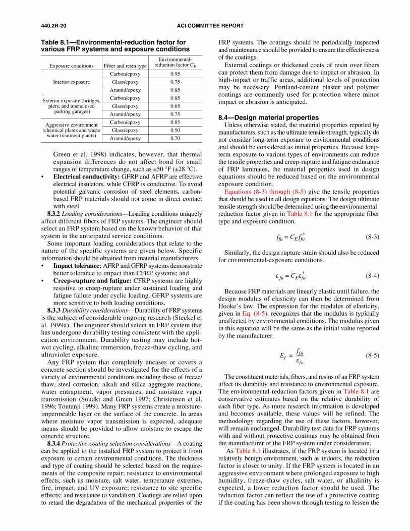
440.2R-20 ACI COMMITTEE REPORT
Green et al. 1998) indicates, however, that thermalexpansion differences do not affect bond for smallranges of temperature change, such as ±50 °F (±28 °C).
• Electrical conductivity: GFRP and AFRP are effectiveelectrical insulators, while CFRP is conductive. To avoidpotential galvanic corrosion of steel elements, carbon-based FRP materials should not come in direct contactwith steel.
8.3.2 Loading considerations—Loading conditions uniquelyaffect different fibers of FRP systems. The engineer shouldselect an FRP system based on the known behavior of thatsystem in the anticipated service conditions.
Some important loading considerations that relate to thenature of the specific systems are given below. Specificinformation should be obtained from material manufacturers.• Impact tolerance: AFRP and GFRP systems demonstrate
better tolerance to impact than CFRP systems; and• Creep-rupture and fatigue: CFRP systems are highly
resistive to creep-rupture under sustained loading andfatigue failure under cyclic loading. GFRP systems aremore sensitive to both loading conditions.
8.3.3 Durability considerations—Durability of FRP systemsis the subject of considerable ongoing research (Steckel etal. 1999a). The engineer should select an FRP system thathas undergone durability testing consistent with the appli-cation environment. Durability testing may include hot-wet cycling, alkaline immersion, freeze-thaw cycling, andultraviolet exposure.
Any FRP system that completely encases or covers aconcrete section should be investigated for the effects of avariety of environmental conditions including those of freeze/thaw, steel corrosion, alkali and silica aggregate reactions,water entrapment, vapor pressures, and moisture vaportransmission (Soudki and Green 1997; Christensen et al.1996; Toutanji 1999). Many FRP systems create a moisture-impermeable layer on the surface of the concrete. In areaswhere moisture vapor transmission is expected, adequatemeans should be provided to allow moisture to escape theconcrete structure.
8.3.4 Protective-coating selection considerations—A coatingcan be applied to the installed FRP system to protect it fromexposure to certain environmental conditions. The thicknessand type of coating should be selected based on the require-ments of the composite repair; resistance to environmentaleffects, such as moisture, salt water, temperature extremes,fire, impact, and UV exposure; resistance to site specificeffects; and resistance to vandalism. Coatings are relied uponto retard the degradation of the mechanical properties of the
FRP systems. The coatings should be periodically inspectedand maintenance should be provided to ensure the effectivenessof the coatings.
External coatings or thickened coats of resin over fiberscan protect them from damage due to impact or abrasion. Inhigh-impact or traffic areas, additional levels of protectionmay be necessary. Portland-cement plaster and polymercoatings are commonly used for protection where minorimpact or abrasion is anticipated.
8.4—Design material propertiesUnless otherwise stated, the material properties reported by
manufacturers, such as the ultimate tensile strength, typically donot consider long-term exposure to environmental conditionsand should be considered as initial properties. Because long-term exposure to various types of environments can reducethe tensile properties and creep-rupture and fatigue enduranceof FRP laminates, the material properties used in designequations should be reduced based on the environmentalexposure condition.
Equations (8-3) through (8-5) give the tensile propertiesthat should be used in all design equations. The design ultimatetensile strength should be determined using the environmental-reduction factor given in Table 8.1 for the appropriate fibertype and exposure condition.
ffu = CE ffu* (8-3)
Similarly, the design rupture strain should also be reducedfor environmental-exposure conditions.
ε fu = CEεfu* (8-4)
Because FRP materials are linearly elastic until failure, thedesign modulus of elasticity can then be determined fromHooke’s law. The expression for the modulus of elasticity,given in Eq. (8-5), recognizes that the modulus is typicallyunaffected by environmental conditions. The modulus givenin this equation will be the same as the initial value reportedby the manufacturer.
(8-5)
The constituent materials, fibers, and resins of an FRP systemaffect its durability and resistance to environmental exposure.The environmental-reduction factors given in Table 8.1 areconservative estimates based on the relative durability ofeach fiber type. As more research information is developedand becomes available, these values will be refined. Themethodology regarding the use of these factors, however,will remain unchanged. Durability test data for FRP systemswith and without protective coatings may be obtained fromthe manufacturer of the FRP system under consideration.
As Table 8.1 illustrates, if the FRP system is located in arelatively benign environment, such as indoors, the reductionfactor is closer to unity. If the FRP system is located in anaggressive environment where prolonged exposure to highhumidity, freeze-thaw cycles, salt water, or alkalinity isexpected, a lower reduction factor should be used. Thereduction factor can reflect the use of a protective coatingif the coating has been shown through testing to lessen the
Efffu
εfu
------=
Table 8.1—Environmental-reduction factor for various FRP systems and exposure conditions
Exposure conditions Fiber and resin typeEnvironmental-
reduction factor CE
Interior exposure
Carbon/epoxy 0.95
Glass/epoxy 0.75
Aramid/epoxy 0.85
Exterior exposure (bridges, piers, and unenclosed
parking garages)
Carbon/epoxy 0.85
Glass/epoxy 0.65
Aramid/epoxy 0.75
Aggressive environment (chemical plants and waste
water treatment plants)
Carbon/epoxy 0.85
Glass/epoxy 0.50
Aramid/epoxy 0.70
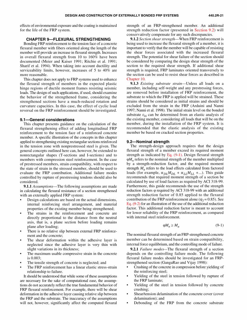
DESIGN AND CONSTRUCTION OF EXTERNALLY BONDED FRP SYSTEMS 440.2R-21
effects of environmental exposure and the coating is maintainedfor the life of the FRP system.
CHAPTER 9—FLEXURAL STRENGTHENINGBonding FRP reinforcement to the tension face of a concrete
flexural member with fibers oriented along the length of themember will provide an increase in flexural strength. Increasesin overall flexural strength from 10 to 160% have beendocumented (Meier and Kaiser 1991; Ritchie et al. 1991;Sharif et al. 1994). When taking into account ductility andserviceability limits, however, increases of 5 to 40% aremore reasonable.
This chapter does not apply to FRP systems used to enhancethe flexural strength of members in the expected plastichinge regions of ductile moment frames resisting seismicloads. The design of such applications, if used, should examinethe behavior of the strengthened frame, considering thestrengthened sections have a much-reduced rotation andcurvature capacities. In this case, the effect of cyclic loadreversal on the FRP reinforcement should be investigated.
9.1—General considerationsThis chapter presents guidance on the calculation of the
flexural strengthening effect of adding longitudinal FRPreinforcement to the tension face of a reinforced concretemember. A specific illustration of the concepts in this chapterapplied to strengthening existing rectangular sections reinforcedin the tension zone with nonprestressed steel is given. Thegeneral concepts outlined here can, however, be extended tononrectangular shapes (T-sections and I-sections) and tomembers with compression steel reinforcement. In the caseof prestressed members, strain compatibility, with respect tothe state of strain in the stressed member, should be used toevaluate the FRP contribution. Additional failure modescontrolled by rupture of prestressing tendons should also beconsidered.
9.1.1 Assumptions—The following assumptions are madein calculating the flexural resistance of a section strengthenedwith an externally applied FRP system:• Design calculations are based on the actual dimensions,
internal reinforcing steel arrangement, and materialproperties of the existing member being strengthened;
• The strains in the reinforcement and concrete aredirectly proportional to the distance from the neutralaxis, that is, a plane section before loading remainsplane after loading;
• There is no relative slip between external FRP reinforce-ment and the concrete;
• The shear deformation within the adhesive layer isneglected since the adhesive layer is very thin withslight variations in its thickness;
• The maximum usable compressive strain in the concreteis 0.003;
• The tensile strength of concrete is neglected; and• The FRP reinforcement has a linear elastic stress-strain
relationship to failure.It should be understood that while some of these assumptions
are necessary for the sake of computational ease, the assump-tions do not accurately reflect the true fundamental behavior ofFRP flexural reinforcement. For example, there will be sheardeformation in the adhesive layer causing relative slip betweenthe FRP and the substrate. The inaccuracy of the assumptionswill not, however, significantly affect the computed flexural
strength of an FRP-strengthened member. An additionalstrength reduction factor (presented in Section 9.2) willconservatively compensate for any such discrepancies.
9.1.2 Section shear strength—When FRP reinforcement isbeing used to increase the flexural strength of a member, it isimportant to verify that the member will be capable of resistingthe shear forces associated with the increased flexuralstrength. The potential for shear failure of the section shouldbe considered by comparing the design shear strength of thesection to the required shear strength. If additional shearstrength is required, FRP laminates oriented transversely tothe section can be used to resist shear forces as described inChapter 10.
9.1.3 Existing substrate strain—Unless all loads on amember, including self-weight and any prestressing forces,are removed before installation of FRP reinforcement, thesubstrate to which the FRP is applied will be strained. Thesestrains should be considered as initial strains and should beexcluded from the strain in the FRP (Arduini and Nanni1997; Nanni et al. 1998). The initial strain level on the bondedsubstrate εbi can be determined from an elastic analysis ofthe existing member, considering all loads that will be on themember, during the installation of the FRP system. It isrecommended that the elastic analysis of the existingmember be based on cracked section properties.
9.2—Nominal strengthThe strength-design approach requires that the design
flexural strength of a member exceed its required momentstrength as indicated by Eq. (9-1). Design flexural strengthφMn refers to the nominal strength of the member multipliedby a strength-reduction factor, and the required momentstrength Mu refers to the load effects calculated from factoredloads (for example, αDLMDL + αLLMLL +...). This guiderecommends that required moment strength of a section becalculated by use of load factors as required by ACI 318-99.Furthermore, this guide recommends the use of the strengthreduction factors φ required by ACI 318-99 with an additionalstrength reduction factor of 0.85 applied to the flexuralcontribution of the FRP reinforcement alone (ψf = 0.85). SeeEq. (9-2) for an illustration of the use of the additional reductionfactor. This additional reduction factor is meant to accountfor lower reliability of the FRP reinforcement, as comparedwith internal steel reinforcement.
φMn ≥ Mu (9-1)
The nominal flexural strength of an FRP-strengthened concretemember can be determined based on strain compatibility,internal force equilibrium, and the controlling mode of failure.
9.2.1 Failure modes—The flexural strength of a sectiondepends on the controlling failure mode. The followingflexural failure modes should be investigated for an FRP-strengthened section (GangaRao and Vijay 1998):• Crushing of the concrete in compression before yielding of
the reinforcing steel;• Yielding of the steel in tension followed by rupture of
the FRP laminate;• Yielding of the steel in tension followed by concrete
crushing;• Shear/tension delamination of the concrete cover (cover
delamination); and• Debonding of the FRP from the concrete substrate
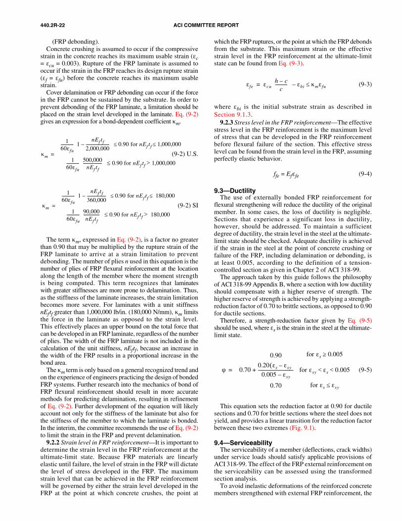
440.2R-22 ACI COMMITTEE REPORT
(FRP debonding).Concrete crushing is assumed to occur if the compressive
strain in the concrete reaches its maximum usable strain (εc= εcu = 0.003). Rupture of the FRP laminate is assumed tooccur if the strain in the FRP reaches its design rupture strain(εf = εfu) before the concrete reaches its maximum usablestrain.
Cover delamination or FRP debonding can occur if the forcein the FRP cannot be sustained by the substrate. In order toprevent debonding of the FRP laminate, a limitation should beplaced on the strain level developed in the laminate. Eq. (9-2)gives an expression for a bond-dependent coefficient κm.
(9-2) U.S.
(9-2) SI
The term κm, expressed in Eq. (9-2), is a factor no greaterthan 0.90 that may be multiplied by the rupture strain of theFRP laminate to arrive at a strain limitation to preventdebonding. The number of plies n used in this equation is thenumber of plies of FRP flexural reinforcement at the locationalong the length of the member where the moment strengthis being computed. This term recognizes that laminateswith greater stiffnesses are more prone to delamination. Thus,as the stiffness of the laminate increases, the strain limitationbecomes more severe. For laminates with a unit stiffnessnEftf greater than 1,000,000 lb/in. (180,000 N/mm), κm limitsthe force in the laminate as opposed to the strain level.This effectively places an upper bound on the total force thatcan be developed in an FRP laminate, regardless of the numberof plies. The width of the FRP laminate is not included in thecalculation of the unit stiffness, nEftf, because an increase inthe width of the FRP results in a proportional increase in thebond area.
The κm term is only based on a general recognized trend andon the experience of engineers practicing the design of bondedFRP systems. Further research into the mechanics of bond ofFRP flexural reinforcement should result in more accuratemethods for predicting delamination, resulting in refinementof Eq. (9-2). Further development of the equation will likelyaccount not only for the stiffness of the laminate but also forthe stiffness of the member to which the laminate is bonded.In the interim, the committee recommends the use of Eq. (9-2)to limit the strain in the FRP and prevent delamination.
9.2.2 Strain level in FRP reinforcement—It is important todetermine the strain level in the FRP reinforcement at theultimate-limit state. Because FRP materials are linearlyelastic until failure, the level of strain in the FRP will dictatethe level of stress developed in the FRP. The maximumstrain level that can be achieved in the FRP reinforcementwill be governed by either the strain level developed in theFRP at the point at which concrete crushes, the point at
which the FRP ruptures, or the point at which the FRP debondsfrom the substrate. This maximum strain or the effectivestrain level in the FRP reinforcement at the ultimate-limitstate can be found from Eq. (9-3).
(9-3)
where εbi is the initial substrate strain as described inSection 9.1.3.
9.2.3 Stress level in the FRP reinforcement—The effectivestress level in the FRP reinforcement is the maximum levelof stress that can be developed in the FRP reinforcementbefore flexural failure of the section. This effective stresslevel can be found from the strain level in the FRP, assumingperfectly elastic behavior.
ffe = Efεfe (9-4)
9.3—DuctilityThe use of externally bonded FRP reinforcement for
flexural strengthening will reduce the ductility of the originalmember. In some cases, the loss of ductility is negligible.Sections that experience a significant loss in ductility,however, should be addressed. To maintain a sufficientdegree of ductility, the strain level in the steel at the ultimate-limit state should be checked. Adequate ductility is achievedif the strain in the steel at the point of concrete crushing orfailure of the FRP, including delamination or debonding, isat least 0.005, according to the definition of a tension-controlled section as given in Chapter 2 of ACI 318-99.
The approach taken by this guide follows the philosophyof ACI 318-99 Appendix B, where a section with low ductilityshould compensate with a higher reserve of strength. Thehigher reserve of strength is achieved by applying a strength-reduction factor of 0.70 to brittle sections, as opposed to 0.90for ductile sections.
Therefore, a strength-reduction factor given by Eq. (9-5)should be used, where εs is the strain in the steel at the ultimate-limit state.
(9-5)
This equation sets the reduction factor at 0.90 for ductilesections and 0.70 for brittle sections where the steel does notyield, and provides a linear transition for the reduction factorbetween these two extremes (Fig. 9.1).
9.4—ServiceabilityThe serviceability of a member (deflections, crack widths)
under service loads should satisfy applicable provisions ofACI 318-99. The effect of the FRP external reinforcement onthe serviceability can be assessed using the transformedsection analysis.
To avoid inelastic deformations of the reinforced concretemembers strengthened with external FRP reinforcement, the
κm
160εfu------------- 1
nEf tf
2,000,000------------------------–
0.90 for nEf tf 1,000,000≤≤
160εfu------------- 500,000
nEf tf-------------------
0.90 for nEf tf 1,000,000>≤
=
κm
160εfu------------- 1
nEf tf
360,000-------------------–
0.90 for nEf tf 180,000≤≤
160εfu------------- 90,000
nEf tf----------------
0.90 for nEf tf 180,000>≤
=
εfe εcuh c–
c-----------
εbi κmεfu≤–=
φ 0.70
0.90
0.20 εs εsy–( )0.005 εsy–
0.70
--------------------------------
for εs 0.005≥
for εsy εs 0.005< <
for εs εsy≤
+
=
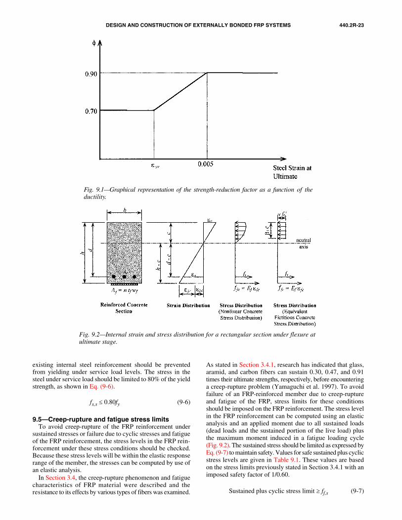
DESIGN AND CONSTRUCTION OF EXTERNALLY BONDED FRP SYSTEMS 440.2R-23
existing internal steel reinforcement should be preventedfrom yielding under service load levels. The stress in thesteel under service load should be limited to 80% of the yieldstrength, as shown in Eq. (9-6).
fs,s ≤ 0.80fy (9-6)
9.5—Creep-rupture and fatigue stress limitsTo avoid creep-rupture of the FRP reinforcement under
sustained stresses or failure due to cyclic stresses and fatigueof the FRP reinforcement, the stress levels in the FRP rein-forcement under these stress conditions should be checked.Because these stress levels will be within the elastic responserange of the member, the stresses can be computed by use ofan elastic analysis.
In Section 3.4, the creep-rupture phenomenon and fatiguecharacteristics of FRP material were described and theresistance to its effects by various types of fibers was examined.
As stated in Section 3.4.1, research has indicated that glass,aramid, and carbon fibers can sustain 0.30, 0.47, and 0.91times their ultimate strengths, respectively, before encounteringa creep-rupture problem (Yamaguchi et al. 1997). To avoidfailure of an FRP-reinforced member due to creep-ruptureand fatigue of the FRP, stress limits for these conditionsshould be imposed on the FRP reinforcement. The stress levelin the FRP reinforcement can be computed using an elasticanalysis and an applied moment due to all sustained loads(dead loads and the sustained portion of the live load) plusthe maximum moment induced in a fatigue loading cycle(Fig. 9.2). The sustained stress should be limited as expressed byEq. (9-7) to maintain safety. Values for safe sustained plus cyclicstress levels are given in Table 9.1. These values are basedon the stress limits previously stated in Section 3.4.1 with animposed safety factor of 1/0.60.
Sustained plus cyclic stress limit ≥ ff,s (9-7)
Fig. 9.1—Graphical representation of the strength-reduction factor as a function of theductility.
Fig. 9.2—Internal strain and stress distribution for a rectangular section under flexure atultimate stage.
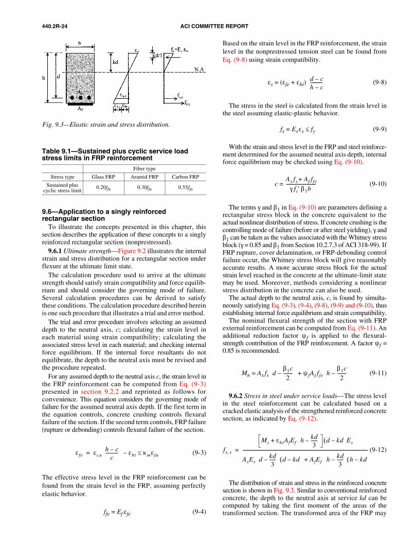
440.2R-24 ACI COMMITTEE REPORT
9.6—Application to a singly reinforcedrectangular section
To illustrate the concepts presented in this chapter, thissection describes the application of these concepts to a singlyreinforced rectangular section (nonprestressed).
9.6.1 Ultimate strength—Figure 9.2 illustrates the internalstrain and stress distribution for a rectangular section underflexure at the ultimate limit state.
The calculation procedure used to arrive at the ultimatestrength should satisfy strain compatibility and force equilib-rium and should consider the governing mode of failure.Several calculation procedures can be derived to satisfythese conditions. The calculation procedure described hereinis one such procedure that illustrates a trial and error method.
The trial and error procedure involves selecting an assumeddepth to the neutral axis, c; calculating the strain level ineach material using strain compatibility; calculating theassociated stress level in each material; and checking internalforce equilibrium. If the internal force resultants do notequilibrate, the depth to the neutral axis must be revised andthe procedure repeated.
For any assumed depth to the neutral axis c, the strain level inthe FRP reinforcement can be computed from Eq. (9-3)presented in section 9.2.2 and reprinted as follows forconvenience. This equation considers the governing mode offailure for the assumed neutral axis depth. If the first term inthe equation controls, concrete crushing controls flexuralfailure of the section. If the second term controls, FRP failure(rupture or debonding) controls flexural failure of the section.
(9-3)
The effective stress level in the FRP reinforcement can befound from the strain level in the FRP, assuming perfectlyelastic behavior.
ffe = Ef εfe (9-4)
εfe εcuh c–
c-----------
εbi κmεfu≤–=
Based on the strain level in the FRP reinforcement, the strainlevel in the nonprestressed tension steel can be found fromEq. (9-8) using strain compatibility.
εs = (εfe + εbi) (9-8)
The stress in the steel is calculated from the strain level inthe steel assuming elastic-plastic behavior.
fs = Esεs ≤ fy (9-9)
With the strain and stress level in the FRP and steel reinforce-ment determined for the assumed neutral axis depth, internalforce equilibrium may be checked using Eq. (9-10).
c = (9-10)
The terms γ and β1 in Eq. (9-10) are parameters defining arectangular stress block in the concrete equivalent to theactual nonlinear distribution of stress. If concrete crushing is thecontrolling mode of failure (before or after steel yielding), γ andβ1 can be taken as the values associated with the Whitney stressblock (γ = 0.85 and β1 from Section 10.2.7.3 of ACI 318-99). IfFRP rupture, cover delamination, or FRP-debonding controlfailure occur, the Whitney stress block will give reasonablyaccurate results. A more accurate stress block for the actualstrain level reached in the concrete at the ultimate-limit statemay be used. Moreover, methods considering a nonlinearstress distribution in the concrete can also be used.
The actual depth to the neutral axis, c, is found by simulta-neously satisfying Eq. (9-3), (9-4), (9-8), (9-9) and (9-10), thusestablishing internal force equilibrium and strain compatibility.
The nominal flexural strength of the section with FRPexternal reinforcement can be computed from Eq. (9-11). Anadditional reduction factor ψf is applied to the flexural-strength contribution of the FRP reinforcement. A factor ψf =0.85 is recommended.
Mn = As fs (9-11)
9.6.2 Stress in steel under service loads—The stress levelin the steel reinforcement can be calculated based on acracked elastic analysis of the strengthened reinforced concretesection, as indicated by Eq. (9-12).
(9-12)
The distribution of strain and stress in the reinforced concretesection is shown in Fig. 9.3. Similar to conventional reinforcedconcrete, the depth to the neutral axis at service kd can becomputed by taking the first moment of the areas of thetransformed section. The transformed area of the FRP may
d c–h c–-----------
As fs Af ffe+
γ fc′ β1b--------------------------
dβ1c
2--------–
ψfAf ffe hβ1c
2--------–
+
fs s,
Ms εbiAfEf h kd3
------– + d kd–( )Es
AsEs d kd3
------– d kd–( ) AfEf h kd
3------–
h kd–( )+
--------------------------------------------------------------------------------------------------------------=
Table 9.1—Sustained plus cyclic service load stress limits in FRP reinforcement
Fiber type
Stress type Glass FRP Aramid FRP Carbon FRP
Sustained plus cyclic stress limit
0.20ffu 0.30ffu 0.55ffu
Fig. 9.3—Elastic strain and stress distribution.
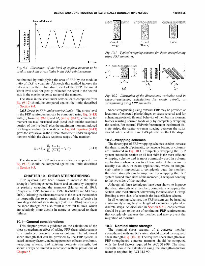
DESIGN AND CONSTRUCTION OF EXTERNALLY BONDED FRP SYSTEMS 440.2R-25
be obtained by multiplying the area of FRP by the modularratio of FRP to concrete. Although this method ignores thedifference in the initial strain level of the FRP, the initialstrain level does not greatly influence the depth to the neutralaxis in the elastic response range of the member.
The stress in the steel under service loads computed fromEq. (9-12) should be compared against the limits describedin Section 9.4.
9.6.3 Stress in FRP under service loads—The stress levelin the FRP reinforcement can be computed using Eq. (9-13)with fs,s from Eq. (9-12) and Ms (in Eq. (9-12)) equal to themoment due to all sustained loads (dead loads and the sustainedportion of the live load) plus the maximum moment inducedin a fatigue loading cycle as shown in Fig. 9.4. Equation (9-13)gives the stress level in the FRP reinforcement under an appliedmoment within the elastic response range of the member.
ff,s = fs,s (9-13)
The stress in the FRP under service loads computed fromEq. (9-13) should be compared against the limits describedin Section 9.5.
CHAPTER 10—SHEAR STRENGTHENINGFRP systems have been shown to increase the shear
strength of existing concrete beams and columns by wrappingor partially wrapping the members (Malvar et al. 1995;Chajes et al. 1995; Norris et al. 1997; Kachlakev and McCurry2000). Orienting the fibers transverse to the axis of the memberor perpendicular to potential shear cracks is effective inproviding additional shear strength (Sato et al. 1996). Increasingthe shear strength can also result in flexural failures, whichare relatively more ductile in nature as compared to shearfailures.
10.1—General considerationsThis chapter presents guidance on the calculation of the
shear-strengthening effect of adding FRP shear reinforcementto a reinforced concrete beam or column. The additionalshear strength that can be provided by the FRP system isbased on many factors, including geometry of beam or column,wrapping scheme, and existing concrete strength, butshould always be limited in accordance with the provisions ofChapter 8.
Ef
Es
----- h kd–
d kd–--------------- εbiEf–
Shear strengthening using external FRP may be provided atlocations of expected plastic hinges or stress reversal and forenhancing postyield flexural behavior of members in momentframes resisting seismic loads only by completely wrappingthe section. For external FRP reinforcement in the form of dis-crete strips, the center-to-center spacing between the stripsshould not exceed the sum of d/4 plus the width of the strip.
10.2—Wrapping schemesThe three types of FRP wrapping schemes used to increase
the shear strength of prismatic, rectangular beams, or columnsare illustrated in Fig. 10.1. Completely wrapping the FRPsystem around the section on all four sides is the most efficientwrapping scheme and is most commonly used in columnapplications where access to all four sides of the column isusually available. In beam applications, where an integralslab makes it impractical to completely wrap the member,the shear strength can be improved by wrapping the FRPsystem around three sides of the member (U-wrap) or bondingto the two sides of the member.
Although all three techniques have been shown to improvethe shear strength of a member, completely wrapping thesection is the most efficient, followed by the three-sided U-wrap.Bonding to two sides of a beam is the least efficient scheme.
In all wrapping schemes, the FRP system can be installedcontinuously along the span length of a member or placed asdiscrete strips. As discussed in Section 8.3.3, considerationshould be given to the use of continuous FRP reinforcementthat completely encases the member and may prevent themigration of moisture.
10.3—Nominal shear strengthThe nominal shear strength of a concrete member
strengthened with an FRP system should exceed the requiredshear strength (Eq. (10-1)). The required shear strength on anFRP-strengthened concrete member should be computedwith the load factors required by ACI 318-99. The shearstrength should be calculated using the strength-reductionfactor φ, required by ACI 318-99.
Fig. 9.4—Illustration of the level of applied moment to beused to check the stress limits in the FRP reinforcement.
Fig. 10.1—Typical wrapping schemes for shear strengtheningusing FRP laminates.
Fig. 10.2—Illustration of the dimensional variables used inshear-strengthening calculations for repair, retrofit, orstrengthening using FRP laminates.
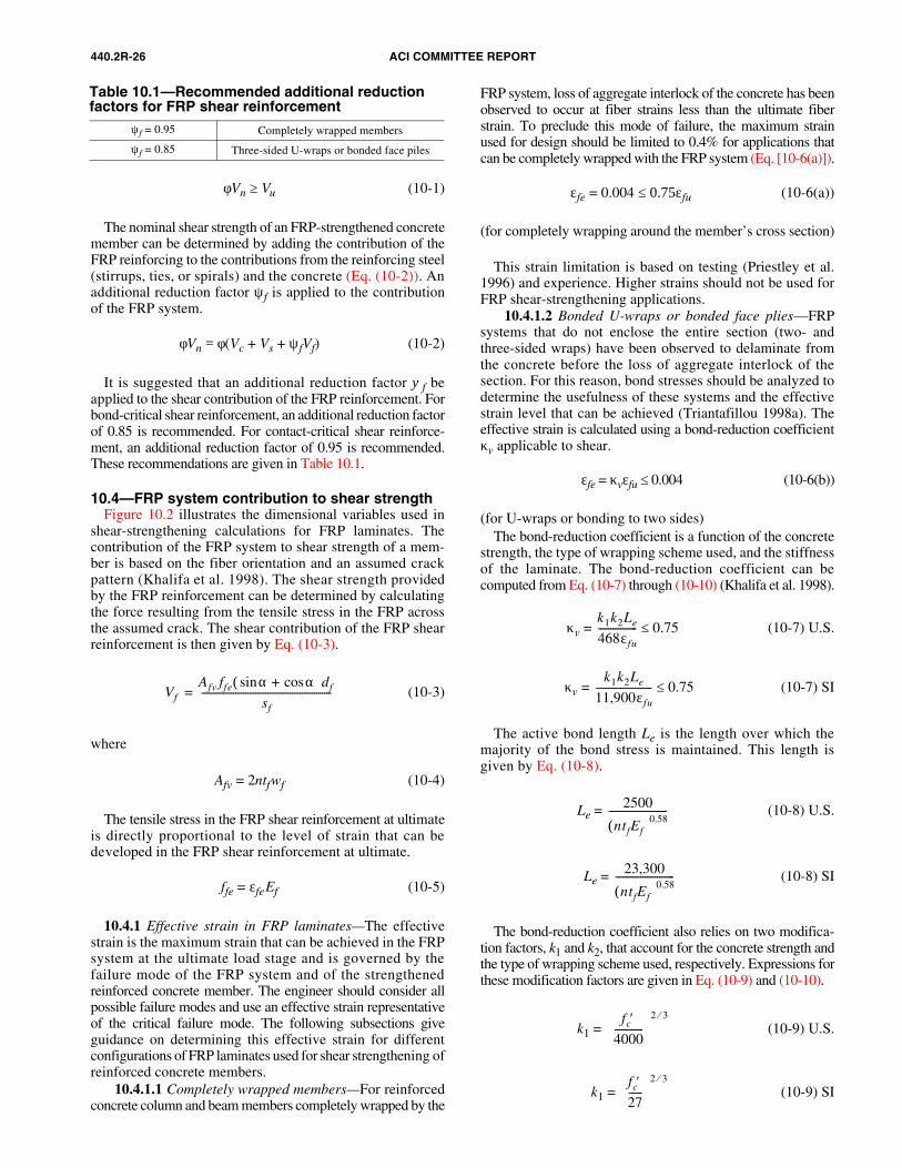
440.2R-26 ACI COMMITTEE REPORT
φVn ≥ Vu (10-1)
The nominal shear strength of an FRP-strengthened concretemember can be determined by adding the contribution of theFRP reinforcing to the contributions from the reinforcing steel(stirrups, ties, or spirals) and the concrete (Eq. (10-2)). Anadditional reduction factor ψf is applied to the contributionof the FRP system.
φVn = φ(Vc + Vs + ψfVf) (10-2)
It is suggested that an additional reduction factor ψf beapplied to the shear contribution of the FRP reinforcement. Forbond-critical shear reinforcement, an additional reduction factorof 0.85 is recommended. For contact-critical shear reinforce-ment, an additional reduction factor of 0.95 is recommended.These recommendations are given in Table 10.1.
10.4—FRP system contribution to shear strengthFigure 10.2 illustrates the dimensional variables used in
shear-strengthening calculations for FRP laminates. Thecontribution of the FRP system to shear strength of a mem-ber is based on the fiber orientation and an assumed crackpattern (Khalifa et al. 1998). The shear strength providedby the FRP reinforcement can be determined by calculatingthe force resulting from the tensile stress in the FRP acrossthe assumed crack. The shear contribution of the FRP shearreinforcement is then given by Eq. (10-3).
(10-3)
where
Afv = 2ntfwf (10-4)
The tensile stress in the FRP shear reinforcement at ultimateis directly proportional to the level of strain that can bedeveloped in the FRP shear reinforcement at ultimate.
ffe = εfeEf (10-5)
10.4.1 Effective strain in FRP laminates—The effectivestrain is the maximum strain that can be achieved in the FRPsystem at the ultimate load stage and is governed by thefailure mode of the FRP system and of the strengthenedreinforced concrete member. The engineer should consider allpossible failure modes and use an effective strain representativeof the critical failure mode. The following subsections giveguidance on determining this effective strain for differentconfigurations of FRP laminates used for shear strengthening ofreinforced concrete members.
10.4.1.1 Completely wrapped members—For reinforcedconcrete column and beam members completely wrapped by the
VfAfv ffe α αcos+sin( )df
sf
-----------------------------------------------------=
FRP system, loss of aggregate interlock of the concrete has beenobserved to occur at fiber strains less than the ultimate fiberstrain. To preclude this mode of failure, the maximum strainused for design should be limited to 0.4% for applications thatcan be completely wrapped with the FRP system (Eq. [10-6(a)]).
εfe = 0.004 ≤ 0.75εfu (10-6(a))
(for completely wrapping around the member’s cross section)
This strain limitation is based on testing (Priestley et al.1996) and experience. Higher strains should not be used forFRP shear-strengthening applications.
10.4.1.2 Bonded U-wraps or bonded face plies—FRPsystems that do not enclose the entire section (two- andthree-sided wraps) have been observed to delaminate fromthe concrete before the loss of aggregate interlock of thesection. For this reason, bond stresses should be analyzed todetermine the usefulness of these systems and the effectivestrain level that can be achieved (Triantafillou 1998a). Theeffective strain is calculated using a bond-reduction coefficientκv applicable to shear.
εfe = κvεfu ≤ 0.004 (10-6(b))
(for U-wraps or bonding to two sides)The bond-reduction coefficient is a function of the concrete
strength, the type of wrapping scheme used, and the stiffnessof the laminate. The bond-reduction coefficient can becomputed from Eq. (10-7) through (10-10) (Khalifa et al. 1998).
κv = (10-7) U.S.
κv = (10-7) SI
The active bond length Le is the length over which themajority of the bond stress is maintained. This length isgiven by Eq. (10-8).
Le = (10-8) U.S.
Le = (10-8) SI
The bond-reduction coefficient also relies on two modifica-tion factors, k1 and k2, that account for the concrete strength andthe type of wrapping scheme used, respectively. Expressions forthese modification factors are given in Eq. (10-9) and (10-10).
k1 = (10-9) U.S.
k1 = (10-9) SI
k1k2Le
468εfu
---------------- 0.75≤
k1k2Le
11,900εfu
----------------------- 0.75≤
2500
ntfEf( )0.58------------------------
23,300
ntfEf( )0.58------------------------
fc′4000------------
2 3⁄
fc′27------
2 3⁄
Table 10.1—Recommended additional reduction factors for FRP shear reinforcement
ψf = 0.95 Completely wrapped members
ψf = 0.85 Three-sided U-wraps or bonded face piles
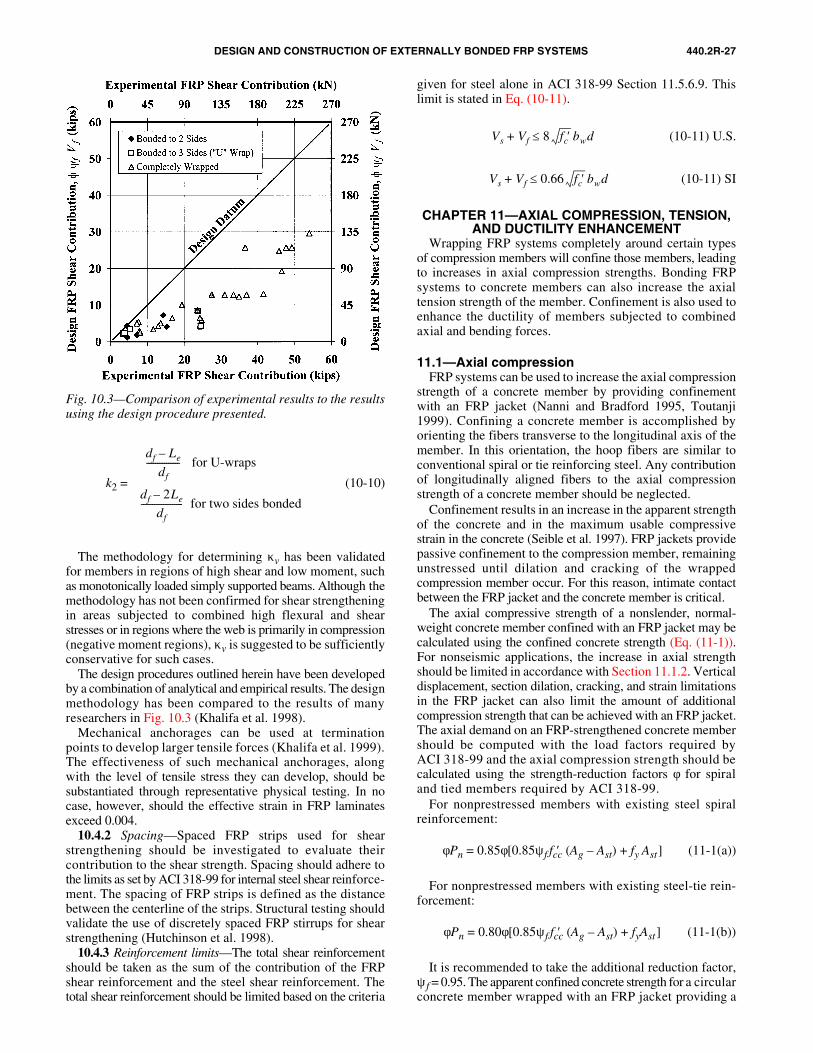
DESIGN AND CONSTRUCTION OF EXTERNALLY BONDED FRP SYSTEMS 440.2R-27
k2 = (10-10)
The methodology for determining κv has been validatedfor members in regions of high shear and low moment, suchas monotonically loaded simply supported beams. Although themethodology has not been confirmed for shear strengtheningin areas subjected to combined high flexural and shearstresses or in regions where the web is primarily in compression(negative moment regions), κv is suggested to be sufficientlyconservative for such cases.
The design procedures outlined herein have been developedby a combination of analytical and empirical results. The designmethodology has been compared to the results of manyresearchers in Fig. 10.3 (Khalifa et al. 1998).
Mechanical anchorages can be used at terminationpoints to develop larger tensile forces (Khalifa et al. 1999).The effectiveness of such mechanical anchorages, alongwith the level of tensile stress they can develop, should besubstantiated through representative physical testing. In nocase, however, should the effective strain in FRP laminatesexceed 0.004.
10.4.2 Spacing—Spaced FRP strips used for shearstrengthening should be investigated to evaluate theircontribution to the shear strength. Spacing should adhere tothe limits as set by ACI 318-99 for internal steel shear reinforce-ment. The spacing of FRP strips is defined as the distancebetween the centerline of the strips. Structural testing shouldvalidate the use of discretely spaced FRP stirrups for shearstrengthening (Hutchinson et al. 1998).
10.4.3 Reinforcement limits—The total shear reinforcementshould be taken as the sum of the contribution of the FRPshear reinforcement and the steel shear reinforcement. Thetotal shear reinforcement should be limited based on the criteria
df Le–
df
--------------- for U-wraps
df 2Le–
df
------------------- for two sides bonded
given for steel alone in ACI 318-99 Section 11.5.6.9. Thislimit is stated in Eq. (10-11).
(10-11) U.S.
(10-11) SI
CHAPTER 11—AXIAL COMPRESSION, TENSION, AND DUCTILITY ENHANCEMENT
Wrapping FRP systems completely around certain typesof compression members will confine those members, leadingto increases in axial compression strengths. Bonding FRPsystems to concrete members can also increase the axialtension strength of the member. Confinement is also used toenhance the ductility of members subjected to combinedaxial and bending forces.
11.1—Axial compressionFRP systems can be used to increase the axial compression
strength of a concrete member by providing confinementwith an FRP jacket (Nanni and Bradford 1995, Toutanji1999). Confining a concrete member is accomplished byorienting the fibers transverse to the longitudinal axis of themember. In this orientation, the hoop fibers are similar toconventional spiral or tie reinforcing steel. Any contributionof longitudinally aligned fibers to the axial compressionstrength of a concrete member should be neglected.
Confinement results in an increase in the apparent strengthof the concrete and in the maximum usable compressivestrain in the concrete (Seible et al. 1997). FRP jackets providepassive confinement to the compression member, remainingunstressed until dilation and cracking of the wrappedcompression member occur. For this reason, intimate contactbetween the FRP jacket and the concrete member is critical.
The axial compressive strength of a nonslender, normal-weight concrete member confined with an FRP jacket may becalculated using the confined concrete strength (Eq. (11-1)).For nonseismic applications, the increase in axial strengthshould be limited in accordance with Section 11.1.2. Verticaldisplacement, section dilation, cracking, and strain limitationsin the FRP jacket can also limit the amount of additionalcompression strength that can be achieved with an FRP jacket.The axial demand on an FRP-strengthened concrete membershould be computed with the load factors required byACI 318-99 and the axial compression strength should becalculated using the strength-reduction factors φ for spiraland tied members required by ACI 318-99.
For nonprestressed members with existing steel spiralreinforcement:
φPn = 0.85φ[0.85ψf fcc′ (Ag – Ast) + fy Ast] (11-1(a))
For nonprestressed members with existing steel-tie rein-forcement:
φPn = 0.80φ[0.85ψf fcc′ (Ag – Ast) + fyAst] (11-1(b))
It is recommended to take the additional reduction factor,ψf = 0.95. The apparent confined concrete strength for a circularconcrete member wrapped with an FRP jacket providing a
Vs Vf 8 fc′ bwd≤+
Vs Vf 0.66 fc′ bwd≤+
Fig. 10.3—Comparison of experimental results to the resultsusing the design procedure presented.
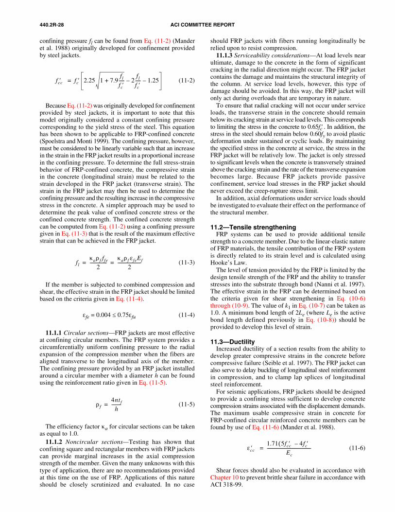
440.2R-28 ACI COMMITTEE REPORT
confining pressure fl can be found from Eq. (11-2) (Manderet al. 1988) originally developed for confinement providedby steel jackets.
(11-2)
Because Eq. (11-2) was originally developed for confinementprovided by steel jackets, it is important to note that thismodel originally considered a constant confining pressurecorresponding to the yield stress of the steel. This equationhas been shown to be applicable to FRP-confined concrete(Spoelstra and Monti 1999). The confining pressure, however,must be considered to be linearly variable such that an increasein the strain in the FRP jacket results in a proportional increasein the confining pressure. To determine the full stress-strainbehavior of FRP-confined concrete, the compressive strainin the concrete (longitudinal strain) must be related to thestrain developed in the FRP jacket (transverse strain). Thestrain in the FRP jacket may then be used to determine theconfining pressure and the resulting increase in the compressivestress in the concrete. A simpler approach may be used todetermine the peak value of confined concrete stress or theconfined concrete strength. The confined concrete strengthcan be computed from Eq. (11-2) using a confining pressuregiven in Eq. (11-3) that is the result of the maximum effectivestrain that can be achieved in the FRP jacket.
(11-3)
If the member is subjected to combined compression andshear, the effective strain in the FRP jacket should be limitedbased on the criteria given in Eq. (11-4).
εfe = 0.004 ≤ 0.75εfu (11-4)
11.1.1 Circular sections—FRP jackets are most effectiveat confining circular members. The FRP system provides acircumferentially uniform confining pressure to the radialexpansion of the compression member when the fibers arealigned transverse to the longitudinal axis of the member.The confining pressure provided by an FRP jacket installedaround a circular member with a diameter h can be foundusing the reinforcement ratio given in Eq. (11-5).
(11-5)
The efficiency factor κa for circular sections can be takenas equal to 1.0.
11.1.2 Noncircular sections—Testing has shown thatconfining square and rectangular members with FRP jacketscan provide marginal increases in the axial compressionstrength of the member. Given the many unknowns with thistype of application, there are no recommendations providedat this time on the use of FRP. Applications of this natureshould be closely scrutinized and evaluated. In no case
should FRP jackets with fibers running longitudinally berelied upon to resist compression.
11.1.3 Serviceability considerations—At load levels nearultimate, damage to the concrete in the form of significantcracking in the radial direction might occur. The FRP jacketcontains the damage and maintains the structural integrity ofthe column. At service load levels, however, this type ofdamage should be avoided. In this way, the FRP jacket willonly act during overloads that are temporary in nature.
To ensure that radial cracking will not occur under serviceloads, the transverse strain in the concrete should remainbelow its cracking strain at service load levels. This correspondsto limiting the stress in the concrete to 0.65fc′ . In addition, thestress in the steel should remain below 0.60fy to avoid plasticdeformation under sustained or cyclic loads. By maintainingthe specified stress in the concrete at service, the stress in theFRP jacket will be relatively low. The jacket is only stressedto significant levels when the concrete is transversely strainedabove the cracking strain and the rate of the transverse expansionbecomes large. Because FRP jackets provide passiveconfinement, service load stresses in the FRP jacket shouldnever exceed the creep-rupture stress limit.
In addition, axial deformations under service loads shouldbe investigated to evaluate their effect on the performance ofthe structural member.
11.2—Tensile strengtheningFRP systems can be used to provide additional tensile
strength to a concrete member. Due to the linear-elastic natureof FRP materials, the tensile contribution of the FRP systemis directly related to its strain level and is calculated usingHooke’s Law.
The level of tension provided by the FRP is limited by thedesign tensile strength of the FRP and the ability to transferstresses into the substrate through bond (Nanni et al. 1997).The effective strain in the FRP can be determined based onthe criteria given for shear strengthening in Eq. (10-6)through (10-9). The value of k1 in Eq. (10-7) can be taken as1.0. A minimum bond length of 2Le (where Le is the activebond length defined previously in Eq. (10-8)) should beprovided to develop this level of strain.
11.3—DuctilityIncreased ductility of a section results from the ability to
develop greater compressive strains in the concrete beforecompressive failure (Seible et al. 1997). The FRP jacket canalso serve to delay buckling of longitudinal steel reinforcementin compression, and to clamp lap splices of longitudinalsteel reinforcement.
For seismic applications, FRP jackets should be designedto provide a confining stress sufficient to develop concretecompression strains associated with the displacement demands.The maximum usable compressive strain in concrete forFRP-confined circular reinforced concrete members can befound by use of Eq. (11-6) (Mander et al. 1988).
(11-6)
Shear forces should also be evaluated in accordance withChapter 10 to prevent brittle shear failure in accordance withACI 318-99.
fcc′ fc′ 2.25 1 7.9fl
fc′-----+ 2
fl
fc′-----– 1.25–=
flκaρf ffe
2----------------
κaρf εfeEf
2----------------------= =
ρf4ntf
h---------=
εcc′1.71 5fcc′ 4fc′–( )
Ec
-----------------------------------------=
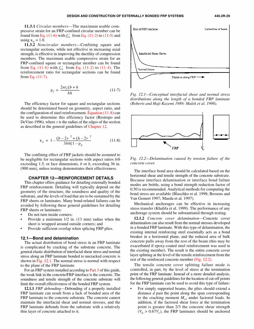
DESIGN AND CONSTRUCTION OF EXTERNALLY BONDED FRP SYSTEMS 440.2R-29
11.3.1 Circular members—The maximum usable com-pressive strain for an FRP-confined circular member can befound from Eq. (11-6) with fcc′ from Eq. (11-2) to (11-5) andusing κa = 1.0.
11.3.2 Noncircular members—Confining square andrectangular sections, while not effective in increasing axialstrength, is effective in improving the ductility of compressionmembers. The maximum usable compressive strain for anFRP-confined square or rectangular member can be foundfrom Eq. (11-6) with fcc′ from Eq. (11-2) to (11-4). Thereinforcement ratio for rectangular sections can be foundfrom Eq. (11-7).
(11-7)
The efficiency factor for square and rectangular sectionsshould be determined based on geometry, aspect ratio, andthe configuration of steel reinforcement. Equation (11-8) canbe used to determine this efficiency factor (Restrepo andDeVino 1996), where r is the radius of the edges of the sectionas described in the general guidelines of Chapter 12.
(11-8)
The confining effect of FRP jackets should be assumed tobe negligible for rectangular sections with aspect ratios b/hexceeding 1.5, or face dimensions, b or h, exceeding 36 in.(900 mm), unless testing demonstrates their effectiveness.
CHAPTER 12—REINFORCEMENT DETAILSThis chapter offers guidance for detailing externally bonded
FRP reinforcement. Detailing will typically depend on thegeometry of the structure, the soundness and quality of thesubstrate, and the levels of load that are to be sustained by theFRP sheets or laminates. Many bond-related failures can beavoided by following these general guidelines for detailingFRP sheets or laminates:• Do not turn inside corners;• Provide a minimum 1/2 in. (13 mm) radius when the
sheet is wrapped around outside corners; and• Provide sufficient overlap when splicing FRP plies.
12.1—Bond and delaminationThe actual distribution of bond stress in an FRP laminate
is complicated by cracking of the substrate concrete. Thegeneral elastic distribution of interfacial shear stress and normalstress along an FRP laminate bonded to uncracked concrete isshown in Fig. 12.1. The normal stress is normal with respectto the plane of the FRP laminate.
For an FRP system installed according to Part 3 of this guide,the weak link in the concrete/FRP interface is the concrete. Thesoundness and tensile strength of the concrete substrate willlimit the overall effectiveness of the bonded FRP system.
12.1.1 FRP debonding—Debonding of a properly installedFRP laminate can result from a lack of bonded area of theFRP laminate to the concrete substrate. The concrete cannotmaintain the interfacial shear and normal stresses, and theFRP laminate debonds from the substrate with a relativelythin layer of concrete attached to it.
ρf2ntf b h+( )
bh---------------------------=
κa 1 b 2r–( )2h 2r–( )2+
3bh 1 ρg–( )--------------------------------------------------–=
The interface bond area should be calculated based on thehorizontal shear and tensile strength of the concrete substrate.Because interface delamination or interface bond failuremodes are brittle, using a bond strength reduction factor of0.50 is recommended. Analytical methods for computing thebond stress are available (Blaschko et al. 1998; Brosens andVan Gemert 1997; Maeda et al. 1997).
Mechanical anchorages can be effective in increasingstress transfer (Khalifa et al. 1999). The performance of anyanchorage system should be substantiated through testing.
12.1.2 Concrete cover delamination—Concrete coverdelamination can also result from the normal stresses developedin a bonded FRP laminate. With this type of delamination, theexisting internal reinforcing steel essentially acts as a bondbreaker in a horizontal plane, and the reduced area of bulkconcrete pulls away from the rest of the beam (this may beexacerbated if epoxy-coated steel reinforcement was used inthe existing member). The result is the entire concrete coverlayer splitting at the level of the tensile reinforcement from therest of the reinforced concrete member (Fig. 12.2).
The tensile concrete cover splitting failure mode iscontrolled, in part, by the level of stress at the terminationpoint of the FRP laminate. Instead of a more detailed analysis,the following general guidelines for the location of cut-off pointsfor the FRP laminate can be used to avoid this type of failure:• For simply supported beams, the plies should extend a
distance d past the point along the span correspondingto the cracking moment Mcr under factored loads. Inaddition, if the factored shear force at the terminationpoint is greater than 2/3 the concrete shear strength(Vu > 0.67Vc), the FRP laminates should be anchored
Fig. 12.1—Conceptual interfacial shear and normal stressdistributions along the length of a bonded FRP laminate(Roberts and Haji-Kazemi 1989; Malek et al. 1998).
Fig. 12.2—Delamination caused by tension failure of theconcrete cover.
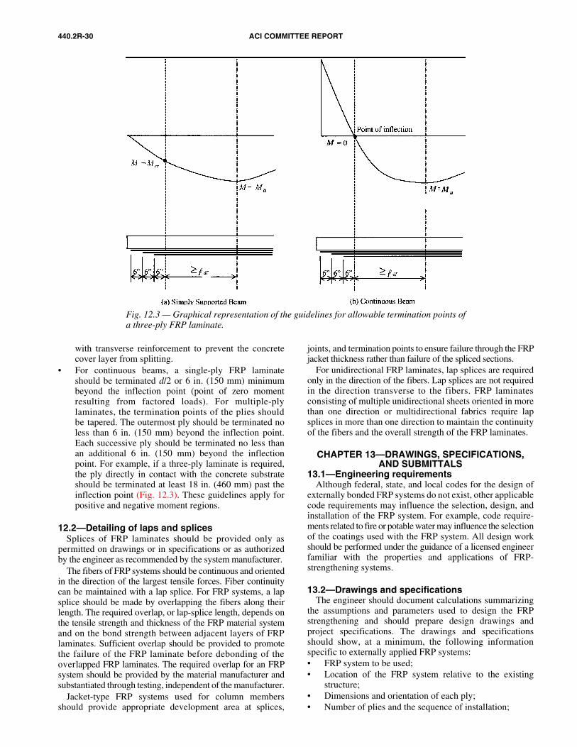
440.2R-30 ACI COMMITTEE REPORT
with transverse reinforcement to prevent the concretecover layer from splitting.
• For continuous beams, a single-ply FRP laminateshould be terminated d/2 or 6 in. (150 mm) minimumbeyond the inflection point (point of zero momentresulting from factored loads). For multiple-plylaminates, the termination points of the plies shouldbe tapered. The outermost ply should be terminated noless than 6 in. (150 mm) beyond the inflection point.Each successive ply should be terminated no less thanan additional 6 in. (150 mm) beyond the inflectionpoint. For example, if a three-ply laminate is required,the ply directly in contact with the concrete substrateshould be terminated at least 18 in. (460 mm) past theinflection point (Fig. 12.3). These guidelines apply forpositive and negative moment regions.
12.2—Detailing of laps and splicesSplices of FRP laminates should be provided only as
permitted on drawings or in specifications or as authorizedby the engineer as recommended by the system manufacturer.
The fibers of FRP systems should be continuous and orientedin the direction of the largest tensile forces. Fiber continuitycan be maintained with a lap splice. For FRP systems, a lapsplice should be made by overlapping the fibers along theirlength. The required overlap, or lap-splice length, depends onthe tensile strength and thickness of the FRP material systemand on the bond strength between adjacent layers of FRPlaminates. Sufficient overlap should be provided to promotethe failure of the FRP laminate before debonding of theoverlapped FRP laminates. The required overlap for an FRPsystem should be provided by the material manufacturer andsubstantiated through testing, independent of the manufacturer.
Jacket-type FRP systems used for column membersshould provide appropriate development area at splices,
joints, and termination points to ensure failure through the FRPjacket thickness rather than failure of the spliced sections.
For unidirectional FRP laminates, lap splices are requiredonly in the direction of the fibers. Lap splices are not requiredin the direction transverse to the fibers. FRP laminatesconsisting of multiple unidirectional sheets oriented in morethan one direction or multidirectional fabrics require lapsplices in more than one direction to maintain the continuityof the fibers and the overall strength of the FRP laminates.
CHAPTER 13—DRAWINGS, SPECIFICATIONS, AND SUBMITTALS
13.1—Engineering requirementsAlthough federal, state, and local codes for the design of
externally bonded FRP systems do not exist, other applicablecode requirements may influence the selection, design, andinstallation of the FRP system. For example, code require-ments related to fire or potable water may influence the selectionof the coatings used with the FRP system. All design workshould be performed under the guidance of a licensed engineerfamiliar with the properties and applications of FRP-strengthening systems.
13.2—Drawings and specificationsThe engineer should document calculations summarizing
the assumptions and parameters used to design the FRPstrengthening and should prepare design drawings andproject specifications. The drawings and specificationsshould show, at a minimum, the following informationspecific to externally applied FRP systems:• FRP system to be used;• Location of the FRP system relative to the existing
structure;• Dimensions and orientation of each ply;• Number of plies and the sequence of installation;
Fig. 12.3 — Graphical representation of the guidelines for allowable termination points ofa three-ply FRP laminate.
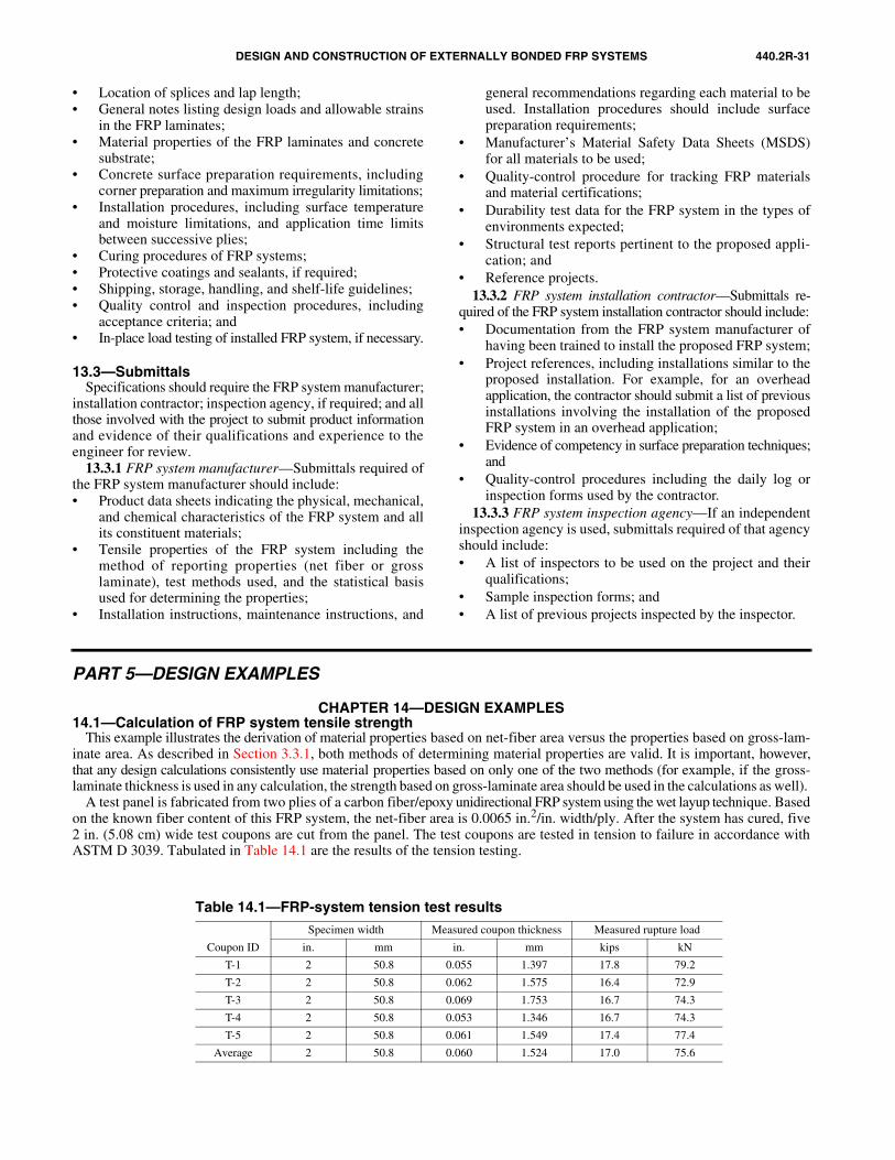
DESIGN AND CONSTRUCTION OF EXTERNALLY BONDED FRP SYSTEMS 440.2R-31
• Location of splices and lap length;• General notes listing design loads and allowable strains
in the FRP laminates;• Material properties of the FRP laminates and concrete
substrate;• Concrete surface preparation requirements, including
corner preparation and maximum irregularity limitations;• Installation procedures, including surface temperature
and moisture limitations, and application time limitsbetween successive plies;
• Curing procedures of FRP systems;• Protective coatings and sealants, if required;• Shipping, storage, handling, and shelf-life guidelines;• Quality control and inspection procedures, including
acceptance criteria; and• In-place load testing of installed FRP system, if necessary.
13.3—SubmittalsSpecifications should require the FRP system manufacturer;
installation contractor; inspection agency, if required; and allthose involved with the project to submit product informationand evidence of their qualifications and experience to theengineer for review.
13.3.1 FRP system manufacturer—Submittals required ofthe FRP system manufacturer should include:• Product data sheets indicating the physical, mechanical,
and chemical characteristics of the FRP system and allits constituent materials;
• Tensile properties of the FRP system including themethod of reporting properties (net fiber or grosslaminate), test methods used, and the statistical basisused for determining the properties;
• Installation instructions, maintenance instructions, and
general recommendations regarding each material to beused. Installation procedures should include surfacepreparation requirements;
• Manufacturer’s Material Safety Data Sheets (MSDS)for all materials to be used;
• Quality-control procedure for tracking FRP materialsand material certifications;
• Durability test data for the FRP system in the types ofenvironments expected;
• Structural test reports pertinent to the proposed appli-cation; and
• Reference projects.13.3.2 FRP system installation contractor—Submittals re-
quired of the FRP system installation contractor should include:• Documentation from the FRP system manufacturer of
having been trained to install the proposed FRP system;• Project references, including installations similar to the
proposed installation. For example, for an overheadapplication, the contractor should submit a list of previousinstallations involving the installation of the proposedFRP system in an overhead application;
• Evidence of competency in surface preparation techniques;and
• Quality-control procedures including the daily log orinspection forms used by the contractor.
13.3.3 FRP system inspection agency—If an independentinspection agency is used, submittals required of that agencyshould include:• A list of inspectors to be used on the project and their
qualifications;• Sample inspection forms; and• A list of previous projects inspected by the inspector.
PART 5—DESIGN EXAMPLES
CHAPTER 14—DESIGN EXAMPLES14.1—Calculation of FRP system tensile strength
This example illustrates the derivation of material properties based on net-fiber area versus the properties based on gross-lam-inate area. As described in Section 3.3.1, both methods of determining material properties are valid. It is important, however,that any design calculations consistently use material properties based on only one of the two methods (for example, if the gross-laminate thickness is used in any calculation, the strength based on gross-laminate area should be used in the calculations as well).
A test panel is fabricated from two plies of a carbon fiber/epoxy unidirectional FRP system using the wet layup technique. Basedon the known fiber content of this FRP system, the net-fiber area is 0.0065 in.2/in. width/ply. After the system has cured, five2 in. (5.08 cm) wide test coupons are cut from the panel. The test coupons are tested in tension to failure in accordance withASTM D 3039. Tabulated in Table 14.1 are the results of the tension testing.
Table 14.1—FRP-system tension test results
Coupon ID
Specimen width Measured coupon thickness Measured rupture load
in. mm in. mm kips kN
T-1 2 50.8 0.055 1.397 17.8 79.2
T-2 2 50.8 0.062 1.575 16.4 72.9
T-3 2 50.8 0.069 1.753 16.7 74.3
T-4 2 50.8 0.053 1.346 16.7 74.3
T-5 2 50.8 0.061 1.549 17.4 77.4
Average 2 50.8 0.060 1.524 17.0 75.6
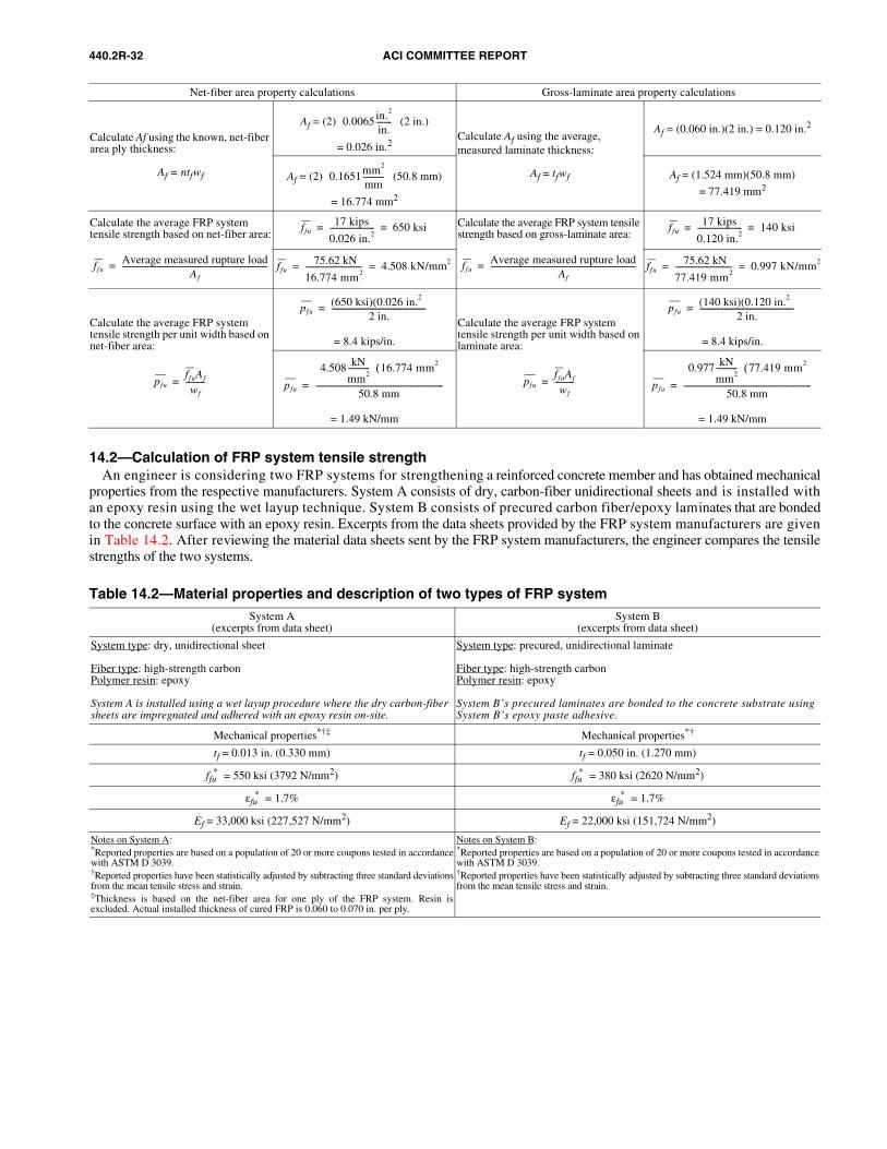
440.2R-32 ACI COMMITTEE REPORT
14.2—Calculation of FRP system tensile strengthAn engineer is considering two FRP systems for strengthening a reinforced concrete member and has obtained mechanical
properties from the respective manufacturers. System A consists of dry, carbon-fiber unidirectional sheets and is installed withan epoxy resin using the wet layup technique. System B consists of precured carbon fiber/epoxy laminates that are bondedto the concrete surface with an epoxy resin. Excerpts from the data sheets provided by the FRP system manufacturers are givenin Table 14.2. After reviewing the material data sheets sent by the FRP system manufacturers, the engineer compares the tensilestrengths of the two systems.
Net-fiber area property calculations Gross-laminate area property calculations
Calculate Af using the known, net-fiber area ply thickness:
Af = ntfwf
Af = (2) (2 in.)
= 0.026 in.2Calculate Af using the average,measured laminate thickness:
Af = tfwf
Af = (0.060 in.)(2 in.) = 0.120 in.2
Af = (2) (50.8 mm)
= 16.774 mm2
Af = (1.524 mm)(50.8 mm)
= 77.419 mm2
Calculate the average FRP systemtensile strength based on net-fiber area:
Calculate the average FRP system tensile strength based on gross-laminate area:
Calculate the average FRP systemtensile strength per unit width based on net-fiber area: = 8.4 kips/in.
Calculate the average FRP systemtensile strength per unit width based on laminate area: = 8.4 kips/in.
= 1.49 kN/mm = 1.49 kN/mm
0.0065in.2
in.--------
0.1651mm2
mm-----------
ffuAverage measured rupture load
Af
---------------------------------------------------------------------------=
ffu17 kips
0.026 in.2----------------------- 650 ksi= =
ffuAverage measured rupture load
Af
---------------------------------------------------------------------------=
ffu17 kips
0.120 in.2----------------------- 140 ksi= =
ffu 75.62 kN
16.774 mm2----------------------------- 4.508 kN/mm2= = ffu
75.62 kN
77.419 mm2----------------------------- 0.997 kN/mm2= =
pfuffuAf
wf
----------=
pfu(650 ksi)(0.026 in.2 )
2 in.-------------------------------------------------=
pfuffuAf
wf
----------=
pfu(140 ksi)(0.120 in.2 )
2 in.-------------------------------------------------=
pfu
4.508 kN
mm2-----------
16.774 mm2( )
50.8 mm------------------------------------------------------------------= pfu
0.977 kN
mm2-----------
77.419 mm2( )
50.8 mm------------------------------------------------------------------=
Table 14.2—Material properties and description of two types of FRP systemSystem A
(excerpts from data sheet)System B
(excerpts from data sheet)
System type: dry, unidirectional sheet
Fiber type: high-strength carbonPolymer resin: epoxy
System A is installed using a wet layup procedure where the dry carbon-fiber sheets are impregnated and adhered with an epoxy resin on-site.
System type: precured, unidirectional laminate
Fiber type: high-strength carbonPolymer resin: epoxy
System B’s precured laminates are bonded to the concrete substrate using System B’s epoxy paste adhesive.
Mechanical properties*†‡ Mechanical properties*†
tf = 0.013 in. (0.330 mm) tf = 0.050 in. (1.270 mm)
ffu* = 550 ksi (3792 N/mm2) ffu
* = 380 ksi (2620 N/mm2)
εfu* = 1.7% εfu
* = 1.7%
Ef = 33,000 ksi (227,527 N/mm2) Ef = 22,000 ksi (151,724 N/mm2)
Notes on System A:*Reported properties are based on a population of 20 or more coupons tested in accordancewith ASTM D 3039.†Reported properties have been statistically adjusted by subtracting three standard deviationsfrom the mean tensile stress and strain.‡Thickness is based on the net-fiber area for one ply of the FRP system. Resin isexcluded. Actual installed thickness of cured FRP is 0.060 to 0.070 in. per ply.
Notes on System B:*Reported properties are based on a population of 20 or more coupons tested in accordancewith ASTM D 3039.†Reported properties have been statistically adjusted by subtracting three standard deviationsfrom the mean tensile stress and strain.
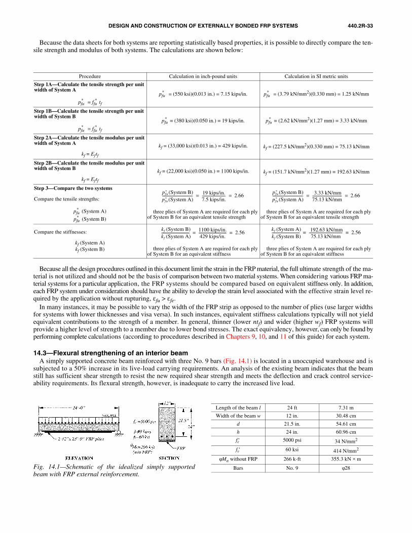
DESIGN AND CONSTRUCTION OF EXTERNALLY BONDED FRP SYSTEMS 440.2R-33
Because the data sheets for both systems are reporting statistically based properties, it is possible to directly compare the ten-sile strength and modulus of both systems. The calculations are shown below:
Procedure Calculation in inch-pound units Calculation in SI metric units
Step 1A—Calculate the tensile strength per unit width of System A
pfu* = ffu
* tf
pfu* = (550 ksi)(0.013 in.) = 7.15 kips/in. pfu
* = (3.79 kN/mm2)(0.330 mm) = 1.25 kN/mm
Step 1B—Calculate the tensile strength per unit width of System B
pfu* = ffu
* tf
pfu* = (380 ksi)(0.050 in.) = 19 kips/in. pfu
* = (2.62 kN/mm2)(1.27 mm) = 3.33 kN/mm
Step 2A—Calculate the tensile modulus per unit width of System A
kf = Eftf
kf = (33,000 ksi)(0.013 in.) = 429 kips/in. kf = (227.5 kN/mm2)(0.330 mm) = 75.13 kN/mm
Step 2B—Calculate the tensile modulus per unit width of System B
kf = Eftf
kf = (22,000 ksi)(0.050 in.) = 1100 kips/in. kf = (151.7 kN/mm2)(1.27 mm) = 192.63 kN/mm
Step 3—Compare the two systems
Compare the tensile strengths:
pfu* (System A)
pfu* (System B)
∴ three plies of System A are required for each ply of System B for an equivalent tensile strength
∴ three plies of System A are required for each ply of System B for an equivalent tensile strength
Compare the stiffnesses:
kf (System A)kf (System B) ∴ three plies of System A are required for each ply
of System B for an equivalent stiffness∴ three plies of System A are required for each ply of System B for an equivalent stiffness
pfu* (System B)
pfu* (System A)
---------------------------------- 19 kips/in.7.5 kips/in.-------------------------- 2.66= =
pfu* (System B)
pfu* (System A)
---------------------------------- 3.33 kN/mm75.13 kN/mm--------------------------------- 2.66= =
kf (System B)kf (System A)------------------------------- 1100 kips/in.
429 kips/in.------------------------------- 2.56= =
kf (System A)kf (System B)------------------------------- 192.63 kN/mm
75.13 kN/mm------------------------------------- 2.56= =
Fig. 14.1—Schematic of the idealized simply supportedbeam with FRP external reinforcement.
Length of the beam l 24 ft 7.31 m
Width of the beam w 12 in. 30.48 cm
d 21.5 in. 54.61 cm
h 24 in. 60.96 cm
fc′ 5000 psi 34 N/mm2
fv′ 60 ksi 414 N/mm2
φMn without FRP 266 k-ft 355.3 kN × m
Bars No. 9 φ28
Because all the design procedures outlined in this document limit the strain in the FRP material, the full ultimate strength of the ma-terial is not utilized and should not be the basis of comparison between two material systems. When considering various FRP ma-terial systems for a particular application, the FRP systems should be compared based on equivalent stiffness only. In addition,each FRP system under consideration should have the ability to develop the strain level associated with the effective strain level re-quired by the application without rupturing, εfu > εfe.
In many instances, it may be possible to vary the width of the FRP strip as opposed to the number of plies (use larger widthsfor systems with lower thicknesses and visa versa). In such instances, equivalent stiffness calculations typically will not yieldequivalent contributions to the strength of a member. In general, thinner (lower ntf) and wider (higher wf) FRP systems willprovide a higher level of strength to a member due to lower bond stresses. The exact equivalency, however, can only be found byperforming complete calculations (according to procedures described in Chapters 9, 10, and 11 of this guide) for each system.
14.3—Flexural strengthening of an interior beamA simply supported concrete beam reinforced with three No. 9 bars (Fig. 14.1) is located in a unoccupied warehouse and is
subjected to a 50% increase in its live-load carrying requirements. An analysis of the existing beam indicates that the beamstill has sufficient shear strength to resist the new required shear strength and meets the deflection and crack control service-ability requirements. Its flexural strength, however, is inadequate to carry the increased live load.
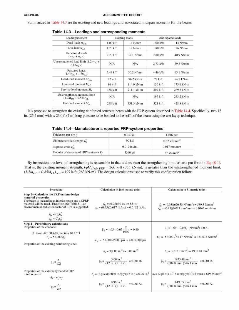
440.2R-34 ACI COMMITTEE REPORT
Table 14.3—Loadings and corresponding momentsLoading/moment Existing loads Anticipated loads
Dead loads wDL 1.00 k/ft 14 N/mm 1.00 k/ft 14 N/mm
Live load wLL 1.20 k/ft 17 N/mm 1.80 k/ft 26 N/mm
Unfactored loads(wDL + wLL) 2.20 k/ft 32.1 N/mm 2.80 k/ft 40.9 N/mm
Unstrengthened load limit (1.2wDL + 0.85wLL) N/A N/A 2.73 k/ft 39.8 N/mm
Factored loads(1.4wDL + 1.7wLL) 3.44 k/ft 50.2 N/mm 4.46 k/ft 65.1 N/mm
Dead-load moment MDL 72 k-ft 96.2 kN-m 72 k-ft 96.2 kN-m
Live-load moment MLL 86 k-ft 114.9 kN-m 130 k-ft 173.6 kN-m
Service-load moment Ms 158 k-ft 211.1 kN-m 202 k-ft 269.8 kN-m
Unstrengthened moment limit (1.2MDL + 0.85MLL) N/A N/A 197 k-ft 263.2 kN-m
Factored moment Mu 248 k-ft 331.3 kN-m 321 k-ft 428.8 kN-m
Table 14.4—Manufacturer’s reported FRP-system propertiesThickness per ply tf 0.040 in. 1.016 mm
Ultimate tensile strength ffu* 90 ksi 0.62 kN/mm2
Rupture strain εfu* 0.017 in./in. 0.017 mm/mm
Modulus of elasticity of FRP laminates Ef 5360 ksi 37 kN/mm2
Summarized in Table 14.3 are the existing and new loadings and associated midspan moments for the beam.
It is proposed to strengthen the existing reinforced concrete beam with the FRP system described in Table 14.4. Specifically, two 12in. (25.4 mm) wide x 23.0 ft (7 m) long plies are to be bonded to the soffit of the beam using the wet layup technique.
By inspection, the level of strengthening is reasonable in that it does meet the strengthening limit criteria put forth in Eq. (8-1).That is, the existing moment strength, (φMn)w/o FRP = 266 k-ft (355 kN-m), is greater than the unstrengthened moment limit,(1.2MDL + 0.85MLL)new = 197 k-ft (263 kN-m). The design calculations used to verify this configuration follow.
Procedure Calculation in inch-pound units Calculation in SI metric units
Step 1—Calculate the FRP-system designmaterial propertiesThe beam is located in an interior space and a CFRPmaterial will be used. Therefore, per Table 8.1, an environmental-reduction factor of 0.95 is suggested.
ffu = CEffu*
εfu = CEεfu*
ffu = (0.95)(90 ksi) = 85 ksiεfu = (0.95)(0.017 in./in.) = 0.0162 in./in.
ffu = (0.95)(620.53 N/mm2) = 589.5 N/mm2
εfu = (0.95)(0.017 mm/mm) = 0.0162 mm/mm
Step 2—Preliminary calculationsProperties of the concrete:
β1 from ACI 318-99, Section 10.2.7.3Ec = 57,000√fc′
Properties of the existing reinforcing steel:
ρs ≡
Properties of the externally bonded FRP reinforcement:
Af = ntfwf
ρf =
β1 = 1.05 – 0.05 = 0.80
= 4,030,000 psi
As = 3(1.00 in.2) = 3.00 in.2
ρs = = 0.00116
Af = (2 plies)(0.040 in./ply)(12 in.) = 0.96 in.2
ρs = = 0.00372
β1 = 1.09 – 0.08fc′ (N/mm2) = 0.81
= 334,672 N/mm2
As = 3(615.7 mm2) = 1935.48 mm2
ρs = = 0.00116
Af = (2 plies)(1.016 mm/ply)(304.8 mm) = 619.35 mm2
ρs = = 0.00372
As
bd------
Af
bd------
fc′1000------------
Ec 57,000 5000 psi=
3.00 in.2
12 in.( ) 21.5 in.( )------------------------------------------
0.96 in.2
12 in.( ) 21.5 in.( )------------------------------------------
Ec 57,000 34.47 N/mm2=
1935.48 mm2
304.8 mm( ) 546.1 mm( )----------------------------------------------------------
619.35 mm2
304.8 mm( ) 546.1 mm( )----------------------------------------------------------
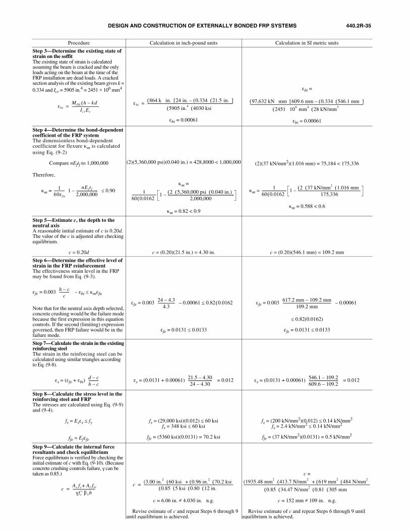
DESIGN AND CONSTRUCTION OF EXTERNALLY BONDED FRP SYSTEMS 440.2R-35
Procedure Calculation in inch-pound units Calculation in SI metric units
Step 3—Determine the existing state of strain on the soffitThe existing state of strain is calculated assuming the beam is cracked and the only loads acting on the beam at the time of the FRP installation are dead loads. A cracked section analysis of the existing beam gives k = 0.334 and Icr = 5905 in.4 = 2451 × 106 mm4
εbi = 0.00061
εbi =
εbi = 0.00061
Step 4—Determine the bond-dependent coefficient of the FRP systemThe dimensionless bond-dependent coefficient for flexure κm is calculated using Eq. (9-2)
Compare nEftf to 1,000,000
Therefore,
κm =
(2)(5,360,000 psi)(0.040 in.) = 428,8000 < 1,000,000
κm =
κm = 0.82 < 0.9
(2)(37 kN/mm2)(1.016 mm) = 75,184 < 175,336
κm =
κm = 0.588 < 0.6
Step 5—Estimate c, the depth to the neutral axisA reasonable initial estimate of c is 0.20d. The value of the c is adjusted after checking equilibrium.
c = 0.20d c = (0.20)(21.5 in.) = 4.30 in. c = (0.20)(546.1 mm) = 109.2 mm
Step 6—Determine the effective level of strain in the FRP reinforcementThe effectiveness strain level in the FRP may be found from Eq. (9-3).
εfe = 0.003 – εbi ≤ κmεfu
Note that for the neutral axis depth selected, concrete crushing would be the failure mode because the first expression in this equation controls. If the second (limiting) expression governed, then FRP failure would be in the failure mode.
εfe = 0.003
εfe = 0.0131 ≤ 0.0133
εfe = 0.003
≤ 0.82(0.0162)
εfe = 0.0131 ≤ 0.0133
Step 7—Calculate the strain in the existing reinforcing steelThe strain in the reinforcing steel can be calculated using similar triangles according to Eq. (9-8).
εs = (εfe + εbi) εs = (0.0131 + 0.00061) = 0.012 εs = (0.0131 + 0.00061) = 0.012
Step 8—Calculate the stress level in thereinforcing steel and FRPThe stresses are calculated using Eq. (9-9) and (9-4).
fs = Esεs ≤ fy
ffe = Efεfe
fs = (29,000 ksi)(0.012) ≤ 60 ksifs = 348 ksi ≤ 60 ksi
ffe = (5360 ksi)(0.0131) = 70.2 ksi
fs = (200 kN/mm2)(0.012) ≤ 0.14 kN/mm2
fs = 2.4 kN/mm2 ≤ 0.14 kN/mm2
ffe = (37 kN/mm2)(0.0131) = 0.5 kN/mm2
Step 9—Calculate the internal force resultants and check equilibriumForce equilibrium is verified by checking the initial estimate of c with Eq. (9-10). (Because concrete crushing controls failure, γ can be taken as 0.85.)
c = 6.06 in. ≠ 4.030 in. n.g.
∴ Revise estimate of c and repeat Steps 6 through 9 until equilibrium is achieved.
c =
c = 152 mm ≠ 109 in. n.g.
∴ Revise estimate of c and repeat Steps 6 through 9 until equilibrium is achieved.
εbiMDL h kd–( )
IcrEc
------------------------------=εbi
864 k in.⋅( ) 24 in. 0.334( ) 21.5 in.( )–[ ]5905 in.4( ) 4030 ksi( )
------------------------------------------------------------------------------------------------= 97,632 kN mm⋅( ) 609.6 mm 0.334( ) 546.1 mm( )–[ ]2451 10⋅ 6 mm4( ) 28 kN/mm2( )
-------------------------------------------------------------------------------------------------------------------------------
160εfu
------------ 1nE ft f
2,000,000------------------------–
0.90≤ 160 0.0162( )--------------------------- 1 2( ) 5,360,000 psi( ) 0.040 in.)( )
2,000,000--------------------------------------------------------------------------–
160 0.0162( )--------------------------- 1 2( ) 37 kN/mm2( ) 1.016 mm( )
175,336----------------------------------------------------------------------–
h c–c
-----------
24 4.3–4.3
------------------- 0.00061 0.82 0.0162( )≤– 617.2 mm 109.2 mm–
109.2 mm------------------------------------------------------
0.00061–
d c–h c–-----------
21.5 4.30–24 4.30–
--------------------------- 546.1 109.2–
609.6 109.2–---------------------------------
cAs fs Af ffe+
γ fc′ β1b-------------------------=
c (3.00 in.2 ) 60 ksi( ) 0.96 in.2( ) 70.2 ksi( )+0.85( ) 5 ksi( ) 0.80( ) 12 in.( )
----------------------------------------------------------------------------------------------------= (1935.48 mm2 ) 413.7 N/mm2( ) 619 mm2( ) 484 N/mm2( )+
0.85( ) 34.47 N/mm2( ) 0.81( ) 305 mm( )---------------------------------------------------------------------------------------------------------------------------------------------
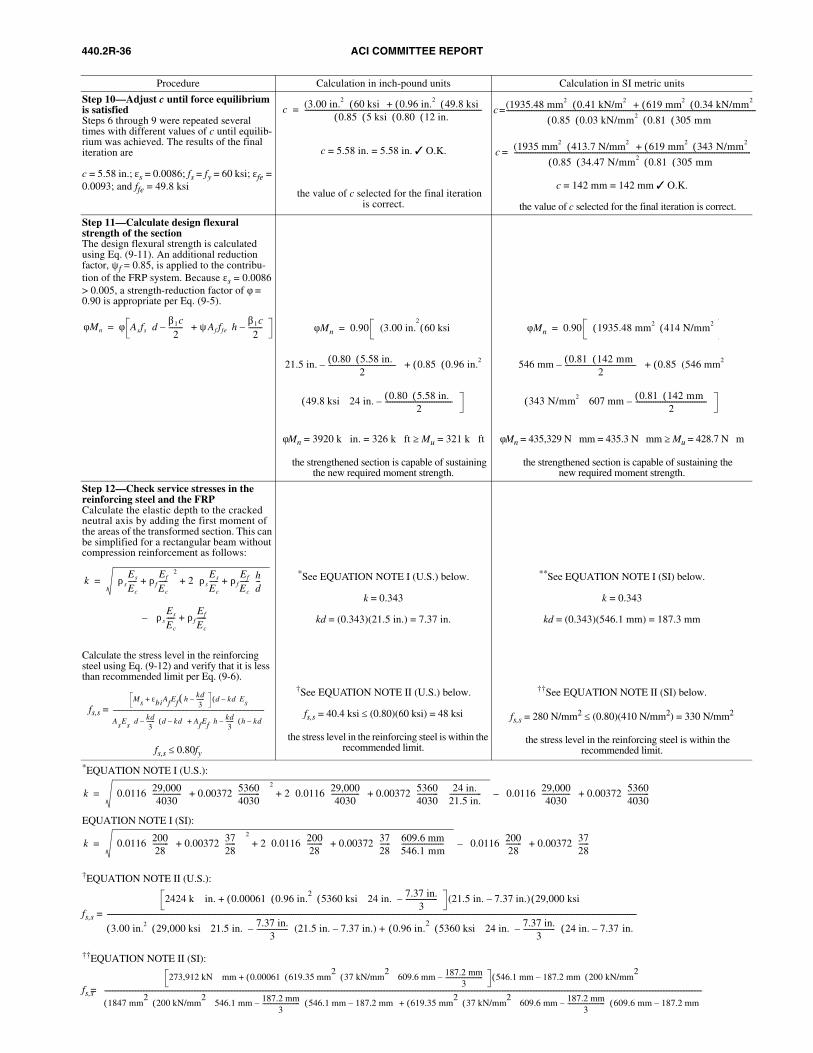
440.2R-36 ACI COMMITTEE REPORT
Procedure Calculation in inch-pound units Calculation in SI metric units
Step 10—Adjust c until force equilibrium is satisfiedSteps 6 through 9 were repeated several times with different values of c until equilib-rium was achieved. The results of the final iteration are
c = 5.58 in.; εs = 0.0086; fs = fy = 60 ksi; εfe = 0.0093; and ffe = 49.8 ksi
c = 5.58 in. = 5.58 in. 3 O.K.
∴ the value of c selected for the final iterationis correct.
c = 142 mm = 142 mm 3 O.K.
∴ the value of c selected for the final iteration is correct.
Step 11—Calculate design flexural strength of the sectionThe design flexural strength is calculated using Eq. (9-11). An additional reduction factor, ψf = 0.85, is applied to the contribu-tion of the FRP system. Because εs = 0.0086 > 0.005, a strength-reduction factor of φ = 0.90 is appropriate per Eq. (9-5).
φMn = 3920 k ⋅ in. = 326 k ⋅ ft ≥ Mu = 321 k ⋅ ft
∴ the strengthened section is capable of sustaining the new required moment strength.
φMn = 435,329 N ⋅ mm = 435.3 N ⋅ mm ≥ Mu = 428.7 N ⋅ m
∴ the strengthened section is capable of sustaining thenew required moment strength.
Step 12—Check service stresses in thereinforcing steel and the FRPCalculate the elastic depth to the cracked neutral axis by adding the first moment of the areas of the transformed section. This can be simplified for a rectangular beam without compression reinforcement as follows:
–
Calculate the stress level in the reinforcing steel using Eq. (9-12) and verify that it is less than recommended limit per Eq. (9-6).
fs,s =
fs,s ≤ 0.80fy
*See EQUATION NOTE I (U.S.) below.
k = 0.343
kd = (0.343)(21.5 in.) = 7.37 in.
†See EQUATION NOTE II (U.S.) below.
fs,s = 40.4 ksi ≤ (0.80)(60 ksi) = 48 ksi
∴ the stress level in the reinforcing steel is within the recommended limit.
**See EQUATION NOTE I (SI) below.
k = 0.343
kd = (0.343)(546.1 mm) = 187.3 mm
††See EQUATION NOTE II (SI) below.
fs,s = 280 N/mm2 ≤ (0.80)(410 N/mm2) = 330 N/mm2
∴ the stress level in the reinforcing steel is within therecommended limit.
*EQUATION NOTE I (U.S.):
EQUATION NOTE I (SI):
†EQUATION NOTE II (U.S.):
fs,s =
††EQUATION NOTE II (SI):
fs,s =
c (3.00 in.2 ) 60 ksi( ) 0.96 in.2( ) 49.8 ksi( )+0.85( ) 5 ksi( ) 0.80( ) 12 in.( )
----------------------------------------------------------------------------------------------------= c (1935.48 mm2 ) 0.41 kN/m2( ) 619 mm2( ) 0.34 kN/mm2( )+
0.85( ) 0.03 kN/mm2( ) 0.81( ) 305 mm( )---------------------------------------------------------------------------------------------------------------------------------------------=
c (1935 mm2 ) 413.7 N/mm2( ) 619 mm2( ) 343 N/mm2( )+
0.85( ) 34.47 N/mm2( ) 0.81( ) 305 mm( )--------------------------------------------------------------------------------------------------------------------------------------=
φMn φ Asfs dβ1c2
--------– ψAf ffe h
β1c2
--------– += φMn 0.90 (3.00 in.
260 ksi( )=
21.5 in. 0.80( ) 5.58 in.( )2
--------------------------------------– 0.85( ) 0.96 in.2( )+
49.8 ksi( ) 24 in. 0.80( ) 5.58 in.( )2
--------------------------------------–
φMn 0.90 1935.48 mm2( ) 414 N/mm2( )=
546 mm 0.81( ) 142 mm( )2
----------------------------------------– 0.85( )(546 mm2 )+
343 N/mm2( ) 607 mm 0.81( ) 142 mm( )2
----------------------------------------–
k ρsEs
Ec
----- ρfEf
Ec
-----+
2
2 ρsEs
Ec
----- ρfEf
Ec
-----+ hd---
+=
ρsEs
Ec
----- ρfEf
Ec
-----+
Ms εbiAfEf h kd3
------–( )+ d kd–( )Es
AsEs d kd3
------– d kd–( ) AfEf h kd
3------–
h kd–( )+------------------------------------------------------------------------------------------------------------------
k 0.0116 29,0004030
---------------- 0.00372 5360
4030------------
+ 2
2 0.0116 29,0004030
---------------- 0.00372 5360
4030------------
24 in.21.5 in.------------------
+ + 0.0116 29,000
4030----------------
0.00372 53604030------------
+ –=
k 0.0116 20028
--------- 0.00372 37
28------
+
2
2 0.0116 20028---------
0.00372 3728------
609.6 mm546.1 mm------------------------
+ + 0.0116 200
28---------
0.00372 3728------
+ –=
2424 k in. 0.00061( ) 0.96 in.2( ) 5360 ksi( ) 24 in. 7.37 in.
3------------------–
+⋅ (21.5 in. 7.37 in.) 29,000 ksi( )–
3.00 in.2( ) 29,000 ksi( ) 21.5 in. 7.37 in.3
------------------– (21.5 in. 7.37 in.) + 0.96 in.
2( ) 5360 ksi( ) 24 in. 7.37 in.3
------------------– 24 in. 7.37 in.–( )–
-----------------------------------------------------------------------------------------------------------------------------------------------------------------------------------------------------------------------------------------------------------------------------------------------------------
273,912 kN mm 0.00061( ) 619.35 mm2
( ) 37 kN/mm2
( ) 609.6 mm 187.2 mm3
------------------------– +⋅ 546.1 mm 187.2 mm–( ) 200 kN/mm
2( )
1847 mm2
( ) 200 kN/mm2
( ) 546.1 mm 187.2 mm3
------------------------– 546.1 mm 187.2 mm–( ) 619.35 mm
2( ) 37 kN/mm
2( ) 609.6 mm 187.2 mm
3------------------------–
609.6 mm 187.2 mm–( )+
--------------------------------------------------------------------------------------------------------------------------------------------------------------------------------------------------------------------------------------------------------------------------------------------------------------------------------------------------------------------------------------------------
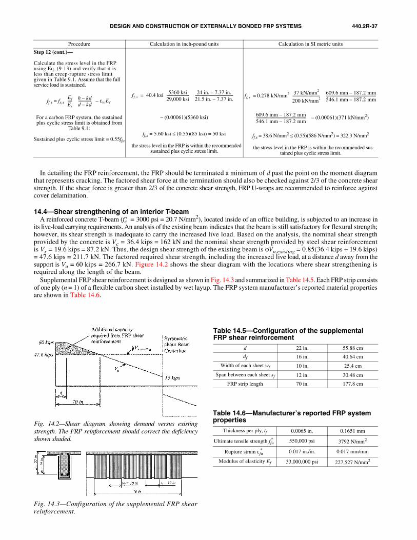
DESIGN AND CONSTRUCTION OF EXTERNALLY BONDED FRP SYSTEMS 440.2R-37
Procedure Calculation in inch-pound units Calculation in SI metric units
Step 12 (cont.)—
Calculate the stress level in the FRP using Eq. (9-13) and verify that it is less than creep-rupture stress limit given in Table 9.1. Assume that the full service load is sustained.
ff,s = fs,s
For a carbon FRP system, the sustained plus cyclic stress limit is obtained from
Table 9.1:
Sustained plus cyclic stress limit = 0.55ffu
– (0.00061)(5360 ksi)
ff,s = 5.60 ksi ≤ (0.55)(85 ksi) = 50 ksi
∴ the stress level in the FRP is within the recommended sustained plus cyclic stress limit.
– (0.00061)(371 kN/mm2)
ff,s = 38.6 N/mm2 ≤ (0.55)(586 N/mm2) = 322.3 N/mm2
∴ the stress level in the FRP is within the recommended sus-tained plus cyclic stress limit.
Ef
Es
----- h kd–
d kd–---------------
εbiEf–ff s, 40.4 ksi 5360 ksi
29,000 ksi-------------------------
24 in. 7.37 in.–21.5 in. 7.37 in.–------------------------------------------
= ff s, 0.278 kN/mm2 37 kN/mm2
200 kN/mm2------------------------------
609.6 mm 187.2 mm–546.1 mm 187.2 mm–-------------------------------------------------------
=
609.6 mm 187.2 mm–546.1 mm 187.2 mm–-------------------------------------------------------
In detailing the FRP reinforcement, the FRP should be terminated a minimum of d past the point on the moment diagramthat represents cracking. The factored shear force at the termination should also be checked against 2/3 of the concrete shearstrength. If the shear force is greater than 2/3 of the concrete shear strength, FRP U-wraps are recommended to reinforce againstcover delamination.
14.4—Shear strengthening of an interior T-beamA reinforced concrete T-beam (fc′ = 3000 psi = 20.7 N/mm2), located inside of an office building, is subjected to an increase in
its live-load carrying requirements. An analysis of the existing beam indicates that the beam is still satisfactory for flexural strength;however, its shear strength is inadequate to carry the increased live load. Based on the analysis, the nominal shear strengthprovided by the concrete is Vc = 36.4 kips = 162 kN and the nominal shear strength provided by steel shear reinforcementis Vs = 19.6 kips = 87.2 kN. Thus, the design shear strength of the existing beam is φVn,existing = 0.85(36.4 kips + 19.6 kips)= 47.6 kips = 211.7 kN. The factored required shear strength, including the increased live load, at a distance d away from thesupport is Vu = 60 kips = 266.7 kN. Figure 14.2 shows the shear diagram with the locations where shear strengthening isrequired along the length of the beam.
Supplemental FRP shear reinforcement is designed as shown in Fig. 14.3 and summarized in Table 14.5. Each FRP strip consistsof one ply (n = 1) of a flexible carbon sheet installed by wet layup. The FRP system manufacturer’s reported material propertiesare shown in Table 14.6.
Fig. 14.2—Shear diagram showing demand versus existingstrength. The FRP reinforcement should correct the deficiencyshown shaded.
Fig. 14.3—Configuration of the supplemental FRP shearreinforcement.
Table 14.5—Configuration of the supplemental FRP shear reinforcement
d 22 in. 55.88 cm
df 16 in. 40.64 cm
Width of each sheet wf 10 in. 25.4 cm
Span between each sheet sf 12 in. 30.48 cm
FRP strip length 70 in. 177.8 cm
Table 14.6—Manufacturer’s reported FRP system properties
Thickness per ply, tf 0.0065 in. 0.1651 mm
Ultimate tensile strength ffu* 550,000 psi 3792 N/mm2
Rupture strain εfu* 0.017 in./in. 0.017 mm/mm
Modulus of elasticity Ef 33,000,000 psi 227,527 N/mm2
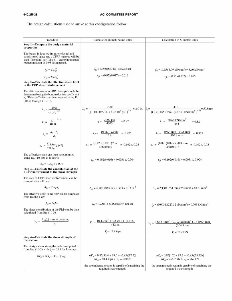
440.2R-38 ACI COMMITTEE REPORT
Procedure Calculation in inch-pound units Calculation in SI metric units
Step 1—Compute the design material properties
The beam is located in an enclosed and conditioned space and a CFRP material will be used. Therefore, per Table 8.1, an environmental-reduction factor of 0.95 is suggested.
ffu = CEffu*
εfu = CEεfu*
ffu = (0.95)(550 ksi) = 522.5 ksi
εfu = (0.95)(0.017) = 0.016
ffu = (0.95)(3.79 kN/mm2) = 3.60 kN/mm2
εfu = (0.95)(0.017) = 0.016
Step 2—Calculate the effective strain level in the FRP shear reinforcement
The effective strain in FRP U-wraps should be determined using the bond-reduction coefficient κv. This coefficient can be computed using Eq. (10-7) through (10-10).
Le =
k1 =
k2 =
The effective strain can then be computed using Eq. (10-6b) as follows:
εfe = κvεfu ≤ 0.004
Le = = 2.0 in.
k1 = = 0.82
k2 =
εfe = 0.192(0.016) = 0.0031 ≤ 0.004
Le = = 50.8mm
k1 = = 0.82
k2 =
εfe = 0.192(0.016) = 0.0031 ≤ 0.004
Step 3—Calculate the contribution of the FRP reinforcement to the shear strength
The area of FRP shear reinforcement can be computed as follows:
Afv = 2nt f wf
The effective stress in the FRP can be computed from Hooke’s law.
ffe = εfeEf
The shear contribution of the FRP can be then calculated from Eq. (10-3).
Afv = 2(1)(0.0065 in.)(10 in.) = 0.13 in.2
ffe = (0.0031)(33,000 ksi) = 102 ksi
Vf = 17.7 kips
Afv = 2(1)(0.1651 mm)(254 mm) = 83.87 mm2
ffe = (0.0031)(227.52 kN/mm2) = 0.703 kN/mm2
Vf = 78.73 kN
Step 4—Calculate the shear strength of the section
The design shear strength can be computed from Eq. (10-2) with ψf = 0.85 for U-wraps.
φVn = φ(Vc + Vs + ψfVf) φVn = 0.85[36.4 + 19.6 + (0.85)(17.7)]φVn = 60.4 kips > Vn = 60 kips
∴ the strengthened section is capable of sustaining the required shear strength.
φVn = 0.85[162 + 87.2 + (0.85)(78.73)]φVn = 268.7 kN > Vn = 267 kN
∴ the strengthened section is capable of sustaining the required shear strength.
2500
ntfEf( )0.58-----------------------
fc′4000------------
2 3⁄
df Le–df
---------------
κvk1k2Le
468εfu
--------------- 0.75≤=
2500
1( ) 0.0065 in.( ) 33 106 psi×( )[ ]0.58
------------------------------------------------------------------------------------
3000 psi4000
--------------------
2 3⁄
16 in. 2.0 in.–16 in.
---------------------------------- 0.875=
κv0.82( ) 0.875( ) 2 in.( )
468 0.016( )-------------------------------------------------- 0.192 0.75≤= =
416
1( ) 0.1651 mm ( ) 227.53 kN/mm2( )[ ]0.58
--------------------------------------------------------------------------------------------------
20.68 kN/mm2
254-----------------------------------
2 3⁄
406.4 mm 50.8 mm–406.4 mm
---------------------------------------------------- 0.875=
κv0.82( ) 0.875( ) 50.8 mm( )
468 0.016( )------------------------------------------------------------- 0.192 0.75≤= =
VfA fvffe α αcos+sin( )df
sf
-----------------------------------------------------= Vf0.13 in.2( ) 102 ksi( ) 1( ) 16 in.( )
12 in.( )---------------------------------------------------------------------------= V f
83.87 mm2( ) 0.703 kN/mm2( ) 1( ) 406.4 mm( )304.8 mm( )
--------------------------------------------------------------------------------------------------------------=
The design calculations used to arrive at this configuration follow.
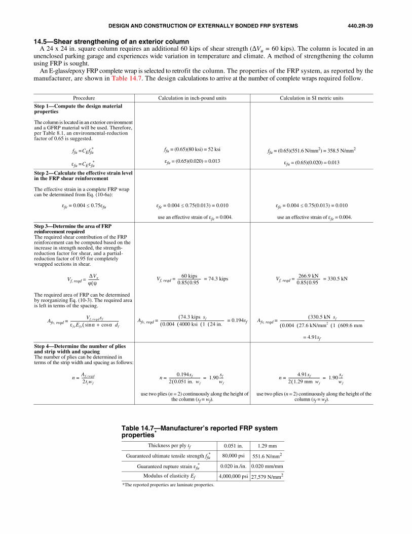
DESIGN AND CONSTRUCTION OF EXTERNALLY BONDED FRP SYSTEMS 440.2R-39
14.5—Shear strengthening of an exterior columnA 24 x 24 in. square column requires an additional 60 kips of shear strength (∆Vu = 60 kips). The column is located in an
unenclosed parking garage and experiences wide variation in temperature and climate. A method of strengthening the columnusing FRP is sought.
An E-glass/epoxy FRP complete wrap is selected to retrofit the column. The properties of the FRP system, as reported by themanufacturer, are shown in Table 14.7. The design calculations to arrive at the number of complete wraps required follow.
Table 14.7—Manufacturer’s reported FRP system properties*
Thickness per ply tf 0.051 in. 1.29 mm
Guaranteed ultimate tensile strength ffu* 80,000 psi 551.6 N/mm2
Guaranteed rupture strain εfu* 0.020 in./in. 0.020 mm/mm
Modulus of elasticity Ef 4,000,000 psi 27,579 N/mm2
*The reported properties are laminate properties.
Procedure Calculation in inch-pound units Calculation in SI metric units
Step 1—Compute the design materialproperties
The column is located in an exterior environment and a GFRP material will be used. Therefore, per Table 8.1, an environmental-reduction factor of 0.65 is suggested.
ffu =CEffu*
εfu =CEεfu*
ffu = (0.65)(80 ksi) = 52 ksi
εfu = (0.65)(0.020) = 0.013
ffu = (0.65)(551.6 N/mm2) = 358.5 N/mm2
εfu = (0.65)(0.020) = 0.013
Step 2—Calculate the effective strain level in the FRP shear reinforcement
The effective strain in a complete FRP wrap can be determined from Eq. (10-6a):
εfe = 0.004 ≤ 0.75εfu εfe = 0.004 ≤ 0.75(0.013) = 0.010
∴ use an effective strain of εfe = 0.004.
εfe = 0.004 ≤ 0.75(0.013) = 0.010
∴ use an effective strain of εfe = 0.004.
Step 3—Determine the area of FRPreinforcement requiredThe required shear contribution of the FRP reinforcement can be computed based on the increase in strength needed, the strength-reduction factor for shear, and a partial-reduction factor of 0.95 for completely wrapped sections in shear.
Vf, reqd =
The required area of FRP can be determined by reorganizing Eq. (10-3). The required area is left in terms of the spacing.
Afv, reqd =
Vf, reqd = = 74.3 kips
Afv, reqd = = 0.194sf
Vf, reqd = = 330.5 kN
Afv, reqd =
= 4.91sf
Step 4—Determine the number of plies and strip width and spacingThe number of plies can be determined in terms of the strip width and spacing as follows:
n = n =
∴ use two plies (n = 2) continuously along the height of the column (sf = wf).
n =
∴ use two plies (n = 2) continuously along the height of the column (sf = wf).
∆Vu
φ ψ( )------------
Vf reqd, sf
εf eEfe α αcos+sin( )df
------------------------------------------------------
60 kips0.85 0.95( )--------------------------
74.3 kips( )sf
0.004( ) 4000 ksi( ) 1( ) 24 in.( )-----------------------------------------------------------------------
266.9 kN0.85 0.95( )--------------------------
330.5 kN( )sf
0.004( ) 27.6 kN/mm2( ) 1( ) 609.6 mm( )----------------------------------------------------------------------------------------------
Af reqd,
2tfwf
--------------0.194sf
2 0.051 in.( )wf
----------------------------------- 1.90sf
wf
-----=4.91sf
2 1.29 mm( )wf
----------------------------------- 1.90sf
wf
-----=
440.2R-40 ACI COMMITTEE REPORT
CHAPTER 15—REFERENCES15.1—Referenced standards and reports
The standards and reports listed below were the latesteditions at the time this document was prepared. Becausethese documents are revised frequently, the reader is advisedto contact the proper sponsoring group if it is desired to referto the latest version.
American Concrete Institute (ACI)201.1R Guide for Making a Condition Survey of Concrete
in Service216R Guide for Determining Fire Endurance of Concrete
Elements224R Control of Cracking in Concrete Structures224.1R Causes, Evaluation, and Repair of Cracks in
Concrete Structures318-99 Building Code Requirements for Structural
Concrete and Commentary364.1R Guide for Evaluation of Concrete Structures Prior
to Rehabilitation437R Strength Evaluation of Existing Concrete Buildings440R-96 State-of-the-Art Report on Fiber Reinforced
Plastic (FRP) Reinforcement for ConcreteStructures
440.1R Guide for the Design and Construction of ConcreteReinforced with FRP Bars
503R Use of Epoxy Compounds with Concrete503.4 Standard Specification for Repairing Concrete
with Epoxy Mortars546R Concrete Repair Guide
American National Standards Institute (ANSI)Z-129.1 Hazardous Industrial Chemicals Precautionary
Labeling
American Society for Testing and Materials (ASTM)D 696 Test Method for Coefficient of Linear Thermal
Expansion of Plastics Between –30 °C and 30 °CD 2240 Test Method for Rubber Hardness—Durometer
HardnessD 2583 Test Method for Indentation Hardness of Rigid
Body Plastics by Means of a Barcol ImpressorD 3039 Test Method for Tensile Properties of Fiber Resin
CompositesD 3165 Test Method for Strength Properties of Adhesives
in Shear by Tension Loading of Single Lap JointLaminated Assemblies
D 3418 Test Method for Transition Temperatures ofPolymers by Thermal Analysis (DTA or DSC)
D 3528 Test Method for Strength Properties of DoubleLap Shear Adhesive Joints by Tension Loading
D 4065 Practice for Determining and Reporting DynamicMechanical Properties of Plastics
D 4541 Test Method for Pull off Strength of CoatingsUsing Portable Adhesion Tester
E 84 Test Method for Surface Burning Characteristicsof Building Materials
E 119 Standard Test Methods for Fire Tests of Build-ing Construction and Materials
Canadian Standards Association (CSA)CSA S806-02 Design and Construction of Building Compo-
nents with Fiber-Reinforced Polymers
Code of Federal RegulationsCFR 16, Part 1500 Hazardous Substances and Articles;
Administration and EnforcementRegulations
CFR 49, Chapter C Transportation
International Conference of Building Officials (ICBO)AC125 Acceptance Criteria for Concrete and Reinforced
and Unreinforced Masonry Strengthening UsingFiber-Reinforced Composite Systems
International Concrete Repair Institute (ICRI)ICRI 03730Guide for Surface Preparation for the Repair of
Deteriorated Concrete Resulting from ReinforcingSteel Corrosion
ICRI 03733Guide for Selecting and Specifying Materials forRepairs of Concrete Surfaces
International Federation for Structural ConcreteFIB 2001 Externally Bonded FRP Reinforcement for
RC Structures
These publications may be obtained from these organizations:
American Concrete InstituteP.O. Box 9094Farmington Hills, MI 48333-9094
American National Standards Institute11 West 42nd StreetNew York, NY 10036
ASTM100 Barr Harbor DriveWest Conshohocken, PA 19428
Canadian Standards Association178 Rexdale Blvd.Toronto, ONM9W 1R3 Canada
Code of Federal RegulationsGovernment Printing Office732 N. Capitol St. N.W.Washington, D.C. 20402
International Conference of Building Officials5360 Workman Mill RoadWhittier, CA 90601-2298
International Concrete Repair Institute3166 S. River Road Suite 132Des Plains, IL 60018
International Federation for Structural ConcreteCase Postale 88CH–1015 Lausanne, Switzerland
DESIGN AND CONSTRUCTION OF EXTERNALLY BONDED FRP SYSTEMS 440.2R-41
15.2—Cited referencesArduini, M., and Nanni, A., 1997, “Behavior of Pre-Cracked
RC Beams Strengthened with Carbon FRP Sheets,” Journal ofComposites in Construction, V. 1, No. 2, pp. 63-70.
Bakis, C. E.; Bank, L. C.; Brown, V. L.; Cosenza, E.;Davalos, J. F.; Lesko, J. J.; Machida, A.; Rizkalla, S. H.; andTriantifillou, T. C., 2002, “Fibre-Reinforced PolymerComposites for Construction-State-of-the-Art Review,”Journal of Composites in Construction, V. 6, No. 2, pp. 73-87.
Benmokrane, B., and Rahman, H., eds., 1998, Durabilityof Fiber Reinforced Polymer (FRP) Composites for Con-struction, University of Sherbrooke, Canada.
Blaschko, M.; Niedermeier, R.; and Zilch, K., 1998,“Bond Failure Modes of Flexural Members Strengthenedwith FRP,” Proceedings of the Second InternationalConference on Composites in Infrastructure, V. 1, Jan.,Tucson, Ariz., pp. 315-327.
Brosens, K., and Van Gemert, D., 1997, “AnchoringStresses Between Concrete and Carbon Fibre ReinforcedLaminates,” Non-Metallic (FRP) Reinforcement for ConcreteStructures, Proceedings of the Third International Symposium,V. 1, Oct., pp. 271-278.
CALTRANS Division of Structures, 1996, PrequalificationRequirements for Alternative Column Casings for SeismicRetrofit (Composites), Section 10.1, California Departmentof Transportation.
Chajes, M.; Januska, T.; Mertz, D.; Thomson, T.; andFinch, W., 1995, “Shear Strengthening of Reinforced ConcreteBeams Using Externally Applied Composite Fabrics,” ACIStructural Journal, V. 92, No. 3, May-June, pp. 295-303.
Christensen, J. B.; Gilstrap, J. M.; and Dolan, C. W., 1996,“Composite Materials Reinforcement of Masonry Structures,”Journal of Architectural Engineering, V. 2, No. 12, pp. 63-70.
Dolan, C., 1999, “FRP Prestressing in the USA,” ConcreteInternational, V. 21, No. 10, Oct., pp. 29-32.
Dolan, C. W.; Rizkalla, S.H.; and Nanni, A., eds, 1999,Fourth International Symposium on Fiber Reinforced PolymerReinforcement for Reinforced Concrete Structures, SP-188,American Concrete Institute, Farmington Hills, Mich.
Ehsani, M. R., 1993, “Glass-Fiber Reinforcing Bars,” Alter-native Materials for the Reinforcement and Prestressing ofConcrete, J.L. Clarke, Blackie Academic & Professional,London, England, pp. 35-54.
Ehsani, M.; Saadatmanesh, H.; and Al-Saidy, A., 1997,“Shear Behavior of URM Retrofitted with FRP Overlays,”Journal of Composites for Construction, V. 1, No. 1, pp. 17-25.
Fardis, M. N., and Khalili, H., 1981, “Concrete Encased inFiberglass Reinforced Plastic,” ACI JOURNAL, 78(6), pp. 440-446.
Fleming, C. J., and King, G. E. M., 1967, “The Developmentof Structural Adhesives for Three Original Uses in SouthAfrica,” RILEM International Symposium, Synthetic Resinsin Building Construction, Paris, pp.75-92.
Fukuyama, H., 1999, “FRP Composites in Japan,” ConcreteInternational, V. 21, No. 10, Oct., pp. 29-32.
GangaRao, H. V. S., and Vijay, P. V., 1998, “BendingBehavior of Concrete Beams Wrapped with Carbon Fabric,”Journal of Structural Engineering, V. 124, No. 1, pp. 3-10.
Green, M.; Bisby, L.; Beaudoin, Y.; and Labossiere, P.,1998, “Effects of Freeze-Thaw Action on the Bond of FRPSheets to Concrete,” Proceedings of the First InternationalConference on Durability of Composites for Construction,Oct., Sherbrooke, Quebec, pp. 179-190.
Hassan, T., and Rizkalla, S., 2002, “Flexural Strengtheningof Prestressed Bridge Slabs with FRP Systems” PCI Journal,V. 47, No. 1, pp. 76-93.
Hawkins, G. F.; Steckel, G. L.; Bauer, J. L.; and Sultan, M.,1998, “Qualification of Composites for Seismic Retrofit ofBridge Columns,” Proceedings of the First InternationalConference on Durability of Composites for Construction,Aug., Sherbrooke, Quebec, pp. 25-36.
Hutchinson, R.; Abdelrahman, A.; Rizkalla, S.; and Rihal,S., 1998, Proceedings of the Second International Confer-ence on Composites in Infrastructure, V. 1, Tucson, Ariz.,Jan., pp. 261-275.
ISIS, 1998, ISIS Standard Test Methods, University ofManitoba, Winnipeg, Manitoba.
Japan Concrete Institute (JCI), 1997, Non-Metallic (FRP)Reinforcement for Concrete Structures, 1 and 2, Tokyo, Japan.
Jones, R.; Swamy, R. N.; and Charif, A., 1988, “PlateSeparation and Anchorage of Reinforced Concrete BeamsStrengthened by Epoxy-Bonded Steel Plates,” StructuralEngineering, 66(5), pp. 85-94.
Kachlakev, D., and McCurry, D., 2000, “Testing of Full-SizeReinforced Concrete Beams Strengthened with FRPComposites: Experimental Results and Design MethodsVerification,” Report No. FHWA-OR-00-19, U.S. Departmentof Transportation Federal Highway Administration.
Katsumata, H.; Kobatake, Y.; and Takeda, T., 1987, “AStudy on the Strengthening with Carbon Fiber for Earth-quake-Resistant Capacity of Existing Concrete Columns,”Proceedings from the Workshop on Repair and Retrofit ofExisting Structures, U.S.-Japan Panel on Wind and SeismicEffects, U.S.-Japan Cooperative Program in Natural Resources,Tsukuba, Japan, pp. 1816-1823.
Khalifa, A.; Alkhrdaji, T.; Nanni, A.; and Lansburg, S.,1999, “Anchorage of Surface Mounted FRP Reinforcement,”Concrete International: Design and Construction, V. 21,No. 10, Oct., pp. 49-54.
Khalifa, A.; Gold, W.; Nanni, A.; and Abel-Aziz M., 1998,“Contribution of Externally Bonded FRP to the Shear Capacityof RC Flexural Members,” Journal of Composites in Con-struction, V. 2, No. 4, pp. 195-203.
Kumahara, S.; Masuda, Y.; and Tanano, Y., 1993, “TensileStrength of Continuous Fiber Bar Under High Temperature,”International Symposium on Fiber-Reinforced PlasticReinforcement for Concrete Structures, SP-138, AmericanConcrete Institute, Farmington Hills, Mich., pp. 731-742.
Maeda, T.; Asano, Y.; Sato, Y.; Ueda, T.; and Kakuta, Y.,1997, “A Study on Bond Mechanism of Carbon Fiber Sheet,”Non-Metallic (FRP) Reinforcement for Concrete Structures,Proceedings of the Third Symposium, V. 1, Oct., pp. 279-286.
Malek, A.; Saadatmanesh, H.; and Ehsani, M., 1998, “Pre-diction of Failure Load of R/C Beams Strengthened with FRPPlate Due to Stress Concentrations at the Plate End,” ACIStructural Journal, V. 95, No. 1, Jan.-Feb., pp. 142-152.
Malvar, L., 1998, “Durability of Composites in ReinforcedConcrete,” Proceedings of the First International Conferenceon Durability of Composites for Construction, Aug.,Sherbrooke, Canada, pp. 361-372.
Malvar, L.; Warren, G.; and Inaba, C., 1995, “Rehabili-tation of Navy Pier Beams With Composite Sheets,” Sec-ond FRP International Symposium on Non-Metallic (FRP)Reinforcement for Concrete Structures, Aug., Gent, Bel-gium, pp. 533-540.
440.2R-42 ACI COMMITTEE REPORT
Mandell, J. F., 1982, “Fatigue Behavior of Fibre-ResinComposites,” Developments in Reinforced Plastics, V. 2,Applied Science Publishers, London, England, pp. 67-107.
Mandell, J. F., and Meier, U., 1983, “Effects of Stress RatioFrequency and Loading Time on the Tensile Fatigue ofGlass-Reinforced Epoxy,” Long Term Behavior of Composites,ASTM STP 813, American Society for Testing and Materials,Philadelphia, Pa., pp. 55-77.
Mander, J. B.; Priestley, M. J. N.; and Park, R., 1988, “Theo-retical Stress-Strain Model for Confined Concrete,” Journal ofStructural Engineering, V. 114, No. 8, pp. 1804-1826.
Marshall, O. S.; Sweeney, S. C.; and Trovillion, J. C.,1999, “Seismic Rehabilitation of Unreinforced MasonryWalls,” Fourth International Symposium on Fiber ReinforcedPolymer Reinforcement for Concrete Structures, SP-188,C. W. Dolan, S. H. Rizkalla, and A. Nanni, eds., American Con-crete Institute, Farmington Hills, Mich., pp. 287-295.
Meier, U., 1987, “Bridge Repair with High PerformanceComposite Materials,” Material und Technik, V. 4, pp. 125-128(in German).
Meier, U., and Kaiser, H., 1991, “Strengthening of Structureswith CFRP Laminates,” Advanced Composite Materials inCivil Engineering Structures, ASCE Specialty Conference,pp. 224-232.
Mindess, S., and Young, J., 1981, Concrete, Prentice-Hall,Englewood Cliffs, N.J., 671 pp.
Mosallam, A.; Chakrabarti, R.; Sim, S.; and Elasnadedy, H.,2000, “Seismic Response of Reinforced Concrete MomentConnections Repaired and Upgraded with FRP Composites,”Innovative Systems for Seismic Repair and Rehabilitation ofStructures, Proceedings, SRRS2 Conference, A. Mosallam, ed.,Fullerton, Calif., Mar. 20-21, pp. 59-72.
Motavalli, M.; Terrasi, G. P.; and Meier, U., 1993, “On theBehavior of Hybrid Aluminum/CFRP Box Beams at LowTemperatures,” Swiss Federal Laboratories for MaterialsTesting and Research (EMPA), Switzerland.
Mutsuyoshi, H.; Uehara, K.; and Machida, A., 1990,“Mechanical Properties and Design Method of ConcreteBeams Reinforced with Carbon Fiber Reinforced Plastics,”Transaction of the Japan Concrete Institute, V. 12, JapanConcrete Institute, Tokyo, Japan, pp. 231-238.
Nanni, A., 1995, “Concrete Repair with Externally BondedFRP Reinforcement,” Concrete International, V. 17, No. 6,June, pp. 22-26.
Nanni, A.; Bakis, C. E.; Boothby, T. E.; Lee, Y. J.; andFrigo, E. L., 1997, “Tensile Reinforcement by FRP SheetsApplied to RC,” 9C/1-8, ICE 97 International CompositesExposition, Jan., Nashville, Tenn., pp. 9C/1 to 8.
Nanni, A., and Bradford, N., 1995, “FRP Jacketed ConcreteUnder Uniaxial Compression,” Construction and BuildingMaterials, V. 9, No. 2, pp. 115-124.
Nanni, A.; Focacci, F.; and Cobb, C. A., 1998, “ProposedProcedure for the Design of RC Flexural Members Strengthenedwith FRP Sheets,” Proceedings, ICCI-98, V. 1, Jan., Tucson,Ariz, pp. 187-201.
Nanni, A., and Gold, W., 1998, “Strength Assessment ofExternal FRP Reinforcement,” Concrete International, V. 20,No. 6, June, pp. 39-42.
National Research Council, 1991, “Life PredictionMethodologies for Composite Materials,” Committee onLife Prediction Methodologies for Composites, NMAB-460,National Materials Advisory Board, Washington, D.C.
Neale, K. W., 2000, “FRPs for Structural Rehabilitation:A Survey of Recent Progress,” Progress in StructuralEngineering and Materials, V. 2, No. 2, pp. 133-138.
Neale, K. W., and Labossière, P., 1997, “State-of-the-ArtReport on Retrofitting and Strengthening by Continuous Fi-bre in Canada,” Non-Metallic (FRP) Reinforcement forConcrete Structures, V. 1, Japan Concrete Institute, Tokyo,Japan, pp. 25-39.
Norris, T.; Saadatmanesh, H.; and Ehsani, M., 1997,“Shear and Flexural Strengthening of R/C Beams withCarbon Fiber Sheets,” Journal of Structural Engineering,V. 123, No. 7, pp. 903-911.
Odagiri, T.; Matsumoto, K.; and Nakai H., 1997, “Fatigueand Relaxation Characteristics of Continuous Aramid FiberReinforced Plastic Rods,” Third International Symposiumon Non-Metallic (FRP) Reinforcement for ConcreteStructures (FRPRCS-3), V. 2, Japan Concrete Institute, To-kyo, Japan, pp. 227-234.
Paulay, T., and Priestley, M., 1992, Seismic Design ofReinforced Concrete and Masonry Buildings, John Wiley &Sons, New York, N.Y., 744 pp.
Priestley, M.; Seible, F.; and Calvi, G., 1996, Seismic Designand Retrofit of Bridges, John Wiley and Sons, New York, N.Y.
Ritchie, P.; Thomas, D.; Lu, L.; and Conneley, G., 1991,“External Reinforcement of Concrete Beams Using FiberReinforced Plastics,” ACI Structural Journal, V. 88, No. 4,July-Aug., pp. 490-500.
Restrepo, J., and DeVino, B., 1996, “Enhancement of theAxial Load-Carrying Capacity of Reinforced ConcreteColumns by Means of Fiber-glass Epoxy Jackets,” Proceedingsof the Advanced Composite Materials in Bridges andStructures II, Montreal, Quebec, pp. 547-553.
Roberts, T. M., and Haji-Kazemi, H., 1989, “TheoreticalStudy of the Behavior of Reinforced Concrete Beams Strength-ened by Externally Bonded Steel Plates,” Proceedings of the In-stitute of Civil Engineers, Part 2, V. 87, No. 9344, pp. 39-55.
Rostasy, F. S., 1987, “Bonding of Steel and GFRP Platesin the Area of Coupling Joints. Talbrucke Kattenbusch,”Research Report No. 3126/1429, Federal Institute for MaterialsTesting, Braunschweig, Germany (in German).
Rostasy, F. S., 1997, “On Durability of FRP in AggressiveEnvironments,” Third International Symposium on Non-Metallic (FRP) Reinforcement for Concrete Structures(FRPRCS-3), V. 2, Japan Concrete Institute, Tokyo, Japan,pp. 107-114.
Roylance, M., and Roylance, O., 1981, “Effect of Moistureon the Fatigue Resistance of an Aramid-Epoxy Composite,”Organic Coatings and Plastics Chemistry, V. 45, AmericanChemical Society, Washington, D.C., pp. 784-788.
Saadatmanesh, H., and Ehsani, M., ed., 1998, SecondInternational Conference on Composites in Infrastructure,ICCI, V. 1 and 2, Tucson, Ariz., 1506 pp.
Saadatmanesh, H., and Tannous, F., 1999a, “Relaxation,Creep, and Fatigue Behavior of Carbon Fiber ReinforcedPlastic Tendons,” ACI Materials Journal, V. 96, No. 2,Mar.-Apr., pp. 143-153.
Sato, Y.; Ueda, T.; Kakuta, Y.; and Tanaka, T., 1996, “ShearReinforcing Effect of Carbon Fiber Sheet Attached to Side ofReinforced Concrete Beams,” Advanced Composite Materialsin Bridges and Structures, M. M. El-Badry, ed., pp. 621-627.
Seible, F.; Priestley, M. J. N.; Hegemier, G. A.; and Innam-orato, D., 1997, “Seismic Retrofit of RC Columns with
DESIGN AND CONSTRUCTION OF EXTERNALLY BONDED FRP SYSTEMS 440.2R-43
Continuous Carbon Fiber Jackets,” Journal of Compositesfor Construction, No. 1, pp. 52-62.
Sharif, A.; Al-Sulaimani, G.; Basunbul, I.; Baluch, M.;and Ghaleb, B., 1994, “Strengthening of Initially LoadedReinforced Concrete Beams Using FRP Plates,” ACI StructuralJournal, V. 91, No. 2, Mar.-Apr., pp. 160-168.
Sheheta, E.; Morphy, R.; and Rizkalla, S., 1999, FourthInternational Symposium on Fiber Reinforced PolymerReinforcement for Concrete Structures, SP-188, C. W.Dolan, S. H. Rizkalla, and A. Nanni, eds., American Con-crete Institute, Farmington Hills, Mich., pp. 157-167.
Soudki, K. A., and Green, M. F., 1997, “Freeze-ThawResponse of CFRP Wrapped Concrete,” Concrete Inter-national, V. 19, No. 8, Aug., pp. 64-67.
Spoelstra, M. R., and Monti, G., 1999, “FRP-ConfinedConcrete Model,” Journal of Composites for Construction,V. 3, No. 3, pp. 143-150.
Steckel, G.; Hawkins, G.; and Bauer, J., 1999a, “DurabilityIssues for Composites in Infrastructure,” 44th InternationalSAMPE Symposium, May, Long Beach, Calif., pp. 2194-2208.
Steckel, G.; Hawkins, G.; and Bauer, J., 1999b, “Qualifica-tions for Seismic Retrofitting of Bridge Columns UsingComposites,” V. 1, 2, and 3, Aerospace Corporation ReportATR-99(7524)-2.
Toutanji, H., 1999, “Stress-Strain Characteristics ofConcrete Columns Externally Confined with AdvancedFiber Composite Sheets,” ACI Materials Journal, V. 96,No. 3, May-June, pp. 397-404.
Triantafillou, T. C., 1998a, “Shear Strengthening of ReinforcedConcrete Beams Using Epoxy-Bonded FRP Composites,” ACIStructural Journal, V. 95, No. 2, Mar.-Apr., pp. 107-115.
Triantafillou, T. C., 1998b, “Strengthening of MasonryStructures Using Epoxy-Bonded FRP Laminates,” Journalof Composites for Construction, No. 2, pp. 96-104.
Wang, N., and Evans, J. T., 1995, “Collapse of ContinuousFiber Composite Beam at Elevated Temperatures,” Composites,V. 26, No. 1, pp. 56-61.
Wolf, R., and Miessler, H. J., 1989, HLV-Spannglieder inder Praxis, Erfahrungen Mit Glasfaserverbundstaben, Beton,2, pp. 47-51.
Wu, W., 1990, “Thermomechanical Properties of FiberReinforced Plastics (FRP) Bars,” PhD dissertation, WestVirginia University, Morgantown, W.Va., 292 pp.
Yamaguchi, T.; Kato, Y.; Nishimura, T.; and Uomoto, T.,1997, “Creep Rupture of FRP Rods Made of Aramid, Carbonand Glass Fibers,” Third International Symposium on Non-Metallic (FRP) Reinforcement for Concrete Structures(FRPRCS-3), V. 2, Japan Concrete Institute, Tokyo, Japan,pp. 179-186.
15.3—Other referencesBaumert, M.; Green, M.; and Erki, M., 1996, “Low
Temperature Behaviour of Concrete Beams Strengthenedwith FRP Sheets,” Proceedings of the 1996 CSCE AnnualConference, Edmonton, Alberta, pp. 179-190.
Brosens, K., and Van Gemert, D., 2001, “Anchorage ofExternally Bonded Reinforcements Subjected to CombinedShear/Bending Action,” Proceedings of the InternationalConference on FRP Composites in Civil Engineering, HongKong, China, pp. 589-596.
Dutta, P. K., 1988, “Structural Fiber Composite Materialsfor Cold Regions,” Journal of Cold Regions Engineering,V. 2, No.3, pp. 124-132.
Fyfe, E. R.; Gee, D. J.; and Milligan, P. B., 1998, “CompositeSystems for Seismic Applications,” Concrete International,V. 20, No. 6, June, pp. 31-33.
Hormann, M.; Seible, F.; Karbhari, V.; and Seim, W.,1998, “Preliminary Structural Tests for Strengthening ofConcrete Slabs Using FRP Composites,” Structural SystemsResearch Project, Report No. TR-98/13, University ofCalifornia, San Diego, Calif., Sept.
Irwin, C. A. K., 1975, “The Strengthening of Concrete Beamsby Bonded Steel Plates,” Technical Report, TRRL Supplemen-tal Report 160UC, Transport and Road Research Laboratory,Department of the Environment, Crowthrone, England.
ISIS Canada Design Manuals, 2001, “StrengtheningReinforced Concrete Structures with Externally-BondedFibre Reinforced Polymers,” The Canadian Network ofCentres of Excellence on Intelligent Sensing for InnovativeStructures, Winnipeg, Manitoba, Canada, 86 pp.
ISIS-Canada, 1998, Standard Test Methods for FRP Rodand Sheet, University of Manitoba, Winnipeg, Manitoba.
Japan Concrete Institute (JCI), 1998, “Technical Reporton Continuous Fiber Reinforced Concrete,” TC 952: Com-mittee on Continuous Fiber Reinforced Concrete, Tokyo.
Japan Society of Civil Engineers (JSCE), 2001, “Recommen-dations for Upgrading of Concrete Structures with Use ofContinuous Fiber Sheets,” Concrete Engineering Series, No. 41,Tokyo, Japan, 250 pp.
Khalifa, A.; Alkhrdaji, T.; Nanni, A.; and Lansburg, S.,1999, “Anchorage of Surface Mounted FRP Reinforcement,”Concrete International, V. 21, No. 10, Oct., pp. 49-54.
MacDonald, M. D., and Calder, A. J. J., 1982, “Bonded SteelPlating for Strengthening Concrete Structures,” InternationalJournal of Adhesion and Adhesives, pp. 119-127.
MacGregor, J., 1997, Reinforced Concrete: Mechanicsand Design, 3rd Edition, Prentice-Hall, Englewood Cliffs,N.J., 939 pp.
Mil Handbook 17, 1999, The Composite MaterialsHandbook—Mil-17, V. 2, Materials Properties, TechnomicPublication, Lancaster, Pa.
Railway Technical Research Institute (RTRI), 1996,“Design and Construction Guidelines for Seismic Retrofitting ofRailway Viaduct Columns Using Aramid Fiber Sheets,” Tokyo.(in Japanese)
Saadatmanesh, J.; Ehsani, M. R.; and Jin, L., 1997, “Repair ofEarthquake-Damaged RC Columns with FRP Wraps,” ACIStructural Journal, V. 95, No. 6, Nov.-Dec., pp. 206-215.
Saadatmanesh, H., and Tannous, F., 1999b, “Long-Term Behavior of Aramid Reinforced Plastic (AFRP)Tendons,” ACI Materials Journal, V. 96, No. 3, May-June, pp. 297-305.
Suppliers of Advanced Composite Materials Associa-tion, 1994, SACMA Recommended Methods, SRM 16-90,Arlington, Va.
Thomas, J., 1978, “FRP Strengthening—Experimental orMainstream Technology,” Concrete International, V. 20,No. 6, June, pp. 57-58.
Todeschini, C.; Bianchini, A; and Kesler, C., 1964,“Behavior of Concrete Columns Reinforced with HighStrength Steels,” ACI JOURNAL, Proceedings, V. 61, No. 6,pp. 701-716.
Triantafillou, T. C., 1998, “Strengthening of Structureswith Advanced FRPs,” Progress in Structural Engineeringand Materials, V. 1, pp. 126-134.
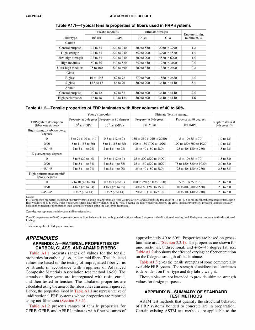
440.2R-44 ACI COMMITTEE REPORT
APPENDIXESAPPENDIX A—MATERIAL PROPERTIES OF
CARBON, GLASS, AND ARAMID FIBERSTable A1.1 presents ranges of values for the tensile
properties for carbon, glass, and aramid fibers. The tabulatedvalues are based on the testing of impregnated fiber yarnsor strands in accordance with Suppliers of AdvancedComposite Materials Association test method 16-90. Thestrands or fiber yarns are impregnated with resin, cured,and then tested in tension. The tabulated properties arecalculated using the area of the fibers; the resin area is ignored.Hence, the properties listed in Table A1.1 are representative ofunidirectional FRP systems whose properties are reportedusing net-fiber area (Section 3.3.1).
Table A1.2 presents ranges of tensile properties forCFRP, GFRP, and AFRP laminates with fiber volumes of
approximately 40 to 60%. Properties are based on gross-laminate area (Section 3.3.1). The properties are shown forunidirectional, bidirectional, and +45/–45 degree fabrics.Table A1.2 also shows the effect of varying the fiber orientationon the 0 degree strength of the laminate.
Table A1.3 gives the tensile strengths of some commerciallyavailable FRP systems. The strength of unidirectional laminatesis dependent on fiber type and dry fabric weight.
These tables are not intended to provide ultimate strengthvalues for design purposes.
APPENDIX B—SUMMARY OF STANDARDTEST METHODS
ASTM test methods that quantify the structural behaviorof FRP systems bonded to concrete are in preparation.Certain existing ASTM test methods are applicable to the
Table A1.1—Typical tensile properties of fibers used in FRP systems
Fiber type
Elastic modulus Ultimate strengthRupture strain, minimum, %103 ksi GPa 103 ksi GPa
Carbon
General purpose 32 to 34 220 to 240 300 to 550 2050 to 3790 1.2
High strength 32 to 34 220 to 240 550 to 700 3790 to 4820 1.4
Ultra-high strength 32 to 34 220 to 240 700 to 900 4820 to 6200 1.5
High modulus 50 to 75 340 to 520 250 to 450 1720 to 3100 0.5
Ultra-high modulus 75 to 100 520 to 690 200 to 350 1380 to 2400 0.2
Glass
E-glass 10 to 10.5 69 to 72 270 to 390 1860 to 2680 4.5
S-glass 12.5 to 13 86 to 90 500 to 700 3440 to 4140 5.4
Aramid
General purpose 10 to 12 69 to 83 500 to 600 3440 to 4140 2.5
High performance 16 to 18 110 to 124 500 to 600 3440 to 4140 1.6
Table A1.2—Tensile properties of FRP laminates with fiber volumes of 40 to 60%
FRP-system description(fiber orientation)
Young’s modulus Ultimate Tensile strength
Rupture strain at 0 degrees, %
Property at 0 degrees Property at 90 degrees Property at 0 degrees Property at 90 degrees
103 ksi (GPa) 103 ksi (MPa) ksi (MPa) ksi (MPa)
High-strength carbon/epoxy, degrees
0 15 to 21 (100 to 140) 0.3 to 1 (2 to 7) 150 to 350 (1020 to 2080) 5 to 10 (35 to 70) 1.0 to 1.5
0/90 8 to 11 (55 to 76) 8 to 11 (55 to 75) 100 to 150 (700 to 1020) 100 to 150 (700 to 1020) 1.0 to 1.5
+45/–45 2 to 4 (14 to 28) 2 to 4 (14 to 28) 25 to 40 (180 to 280) 25 to 40 (180 to 280) 1.5 to 2.5
E-glass/epoxy, degrees
0 3 to 6 (20 to 40) 0.3 to 1 (2 to 7) 75 to 200 (520 to 1400) 5 to 10 (35 to 70) 1.5 to 3.0
0/90 2 to 5 (14 to 34) 2 to 5 (14 to 35) 75 to 150 (520 to 1020) 75 to 150 (520 to 1020) 2.0 to 3.0
+45/–45 2 to 3 (14 to 21) 2 to 3 (14 to 20) 25 to 40 (180 to 280) 25 to 40 (180 to 280) 2.5 to 3.5
High-performance aramid/epoxy, degrees
0 7 to 10 (48 to 68) 0.3 to 1 (2 to 7) 100 to 250 (700 to 1720) 5 to 10 (35 to 70) 2.0 to 3.0
0/90 4 to 5 (28 to 34) 4 to 5 (28 to 35) 40 to 80 (280 to 550) 40 to 80 (280 to 550) 2.0 to 3.0
+45/–45 1 to 2 (7 to 14) 1 to 2 (7 to 14) 20 to 30 (140 to 210) 20 to 30 (140 to 210) 2.0 to 3.0
Notes:FRP composite properties are based on FRP systems having an approximate fiber volume of 50% and a composite thickness of 0.1 in. (2.5 mm). In general, precured systems have fiber volumes of 40 to 60%, while wet layup systems have fiber volumes of 25 to 40%. Because the fiber volume influences the gross-laminate properties, precured laminates usually have higher mechanical properties than laminates created using the wet layup technique.
Zero degrees represents unidirectional fiber orientation.
Zero/90 degrees (or +45/–45 degrees) represents fiber balanced in two orthogonal directions, where 0 degrees is the direction of loading, and 90 degrees is normal to the direction of loading.
Tension is applied to 0 degrees direction.
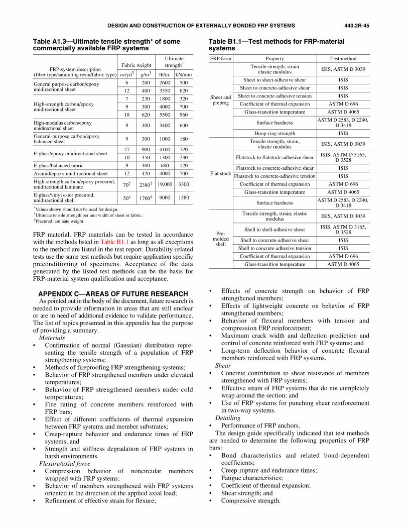
DESIGN AND CONSTRUCTION OF EXTERNALLY BONDED FRP SYSTEMS 440.2R-45
FRP material. FRP materials can be tested in accordancewith the methods listed in Table B1.1 as long as all exceptionsto the method are listed in the test report. Durability-relatedtests use the same test methods but require application specificpreconditioning of specimens. Acceptance of the datagenerated by the listed test methods can be the basis forFRP-material system qualification and acceptance.
APPENDIX C—AREAS OF FUTURE RESEARCHAs pointed out in the body of the document, future research is
needed to provide information in areas that are still unclearor are in need of additional evidence to validate performance.The list of topics presented in this appendix has the purposeof providing a summary.
Materials• Confirmation of normal (Gaussian) distribution repre-
senting the tensile strength of a population of FRPstrengthening systems;
• Methods of fireproofing FRP strengthening systems;• Behavior of FRP strengthened members under elevated
temperatures;• Behavior of FRP strengthened members under cold
temperatures;• Fire rating of concrete members reinforced with
FRP bars;• Effect of different coefficients of thermal expansion
between FRP systems and member substrates;• Creep-rupture behavior and endurance times of FRP
systems; and• Strength and stiffness degradation of FRP systems in
harsh environments.Flexure/axial force
• Compression behavior of noncircular memberswrapped with FRP systems;
• Behavior of members strengthened with FRP systemsoriented in the direction of the applied axial load;
• Refinement of effective strain for flexure;
• Effects of concrete strength on behavior of FRPstrengthened members;
• Effects of lightweight concrete on behavior of FRPstrengthened members;
• Behavior of flexural members with tension andcompression FRP reinforcement;
• Maximum crack width and deflection prediction andcontrol of concrete reinforced with FRP systems; and
• Long-term deflection behavior of concrete flexuralmembers reinforced with FRP systems.
Shear• Concrete contribution to shear resistance of members
strengthened with FRP systems;• Effective strain of FRP systems that do not completely
wrap around the section; and• Use of FRP systems for punching shear reinforcement
in two-way systems.Detailing
• Performance of FRP anchors. The design guide specifically indicated that test methods
are needed to determine the following properties of FRPbars:• Bond characteristics and related bond-dependent
coefficients;• Creep-rupture and endurance times;• Fatigue characteristics; • Coefficient of thermal expansion; • Shear strength; and• Compressive strength.
Table A1.3—Ultimate tensile strength* of some commercially available FRP systems
FRP-system description(fiber type/saturating resin/fabric type)
Fabric weightUltimate strength†
oz/yd3 g/m3 lb/in. kN/mm
General purpose carbon/epoxyunidirectional sheet
6 200 2600 500
12 400 3550 620
High-strength carbon/epoxyunidirectional sheet
7 230 1800 320
9 300 4000 700
18 620 5500 960
High-modulus carbon/epoxyunidirectional sheet 9 300 3400 600
General-purpose carbon/epoxy balanced sheet 9 300 1000 180
E-glass/epoxy unidirectional sheet27 900 4100 720
10 350 1300 230
E-glass/balanced fabric 9 300 680 120
Aramid/epoxy unidirectional sheet 12 420 4000 700
High-strength carbon/epoxy precured, unidirectional laminate 70‡ 2380‡ 19,000 3300
E-glass/vinyl ester precured,unidirectional shell 50‡ 1700‡ 9000 1580
*Values shown should not be used for design.†Ultimate tensile strength per unit width of sheet or fabric.‡Precured laminate weight.
Table B1.1—Test methods for FRP-material systemsFRP form Property Test method
Sheet and prepreg
Tensile strength, strainelastic modulus ISIS, ASTM D 3039
Sheet to sheet-adhesive shear ISIS
Sheet to concrete-adhesive shear ISIS
Sheet to concrete-adhesive tension ISIS
Coefficient of thermal expansion ASTM D 696
Glass-transition temperature ASTM D 4065
Surface hardness ASTM D 2583, D 2240, D 3418
Hoop-ring strength ISIS
Flat stock
Tensile strength, strain,elastic modulus ISIS, ASTM D 3039
Flatstock to flatstock-adhesive shear ISIS, ASTM D 3165,D 3528
Flatstock to concrete-adhesive shear ISIS
Flatstock to concrete-adhesive tension ISIS
Coefficient of thermal expansion ASTM D 696
Glass-transition temperature ASTM D 4065
Surface hardness ASTM D 2583, D 2240, D 3418
Pre-molded
shell
Tensile strength, strain, elasticmodulus ISIS, ASTM D 3039
Shell to shell-adhesive shear ISIS, ASTM D 3165,D 3528
Shell to concrete-adhesive shear ISIS
Shell to concrete-adhesive tension ISIS
Coefficient of thermal expansion ASTM D 696
Glass-transition temperature ASTM D 4065
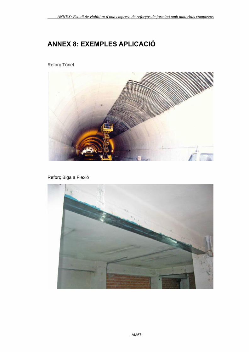
ANNEX: Estudi de viabilitat d'una empresa de reforços de formigó amb materials compostos
- AM67 -
ANNEX 8: EXEMPLES APLICACIÓ
Reforç Túnel
Reforç Biga a Flexió
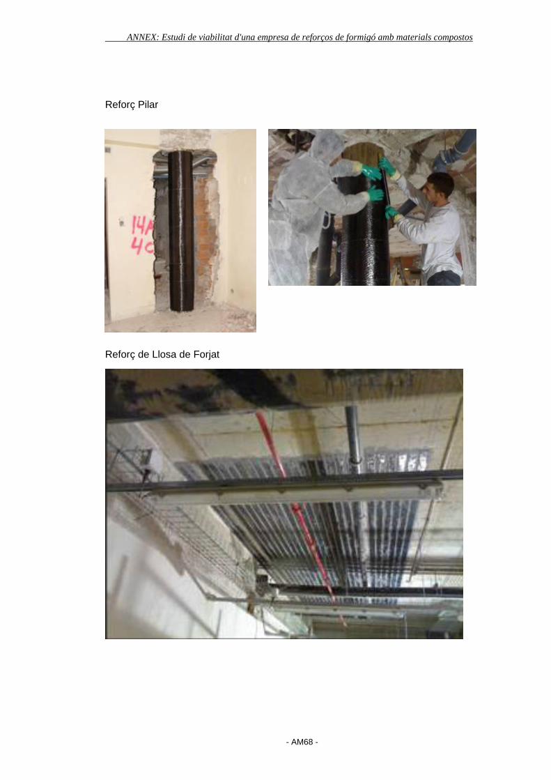
ANNEX: Estudi de viabilitat d'una empresa de reforços de formigó amb materials compostos
- AM68 -
Reforç Pilar
Reforç de Llosa de Forjat

ANNEX: Estudi de viabilitat d'una empresa de reforços de formigó amb materials compostos
- AM69 -
ANNEX 9: “PUNT VERD” GESTIÓ RESIDUS

ANNEX: Estudi de viabilitat d'una empresa de reforços de formigó amb materials compostos
- AM70 -
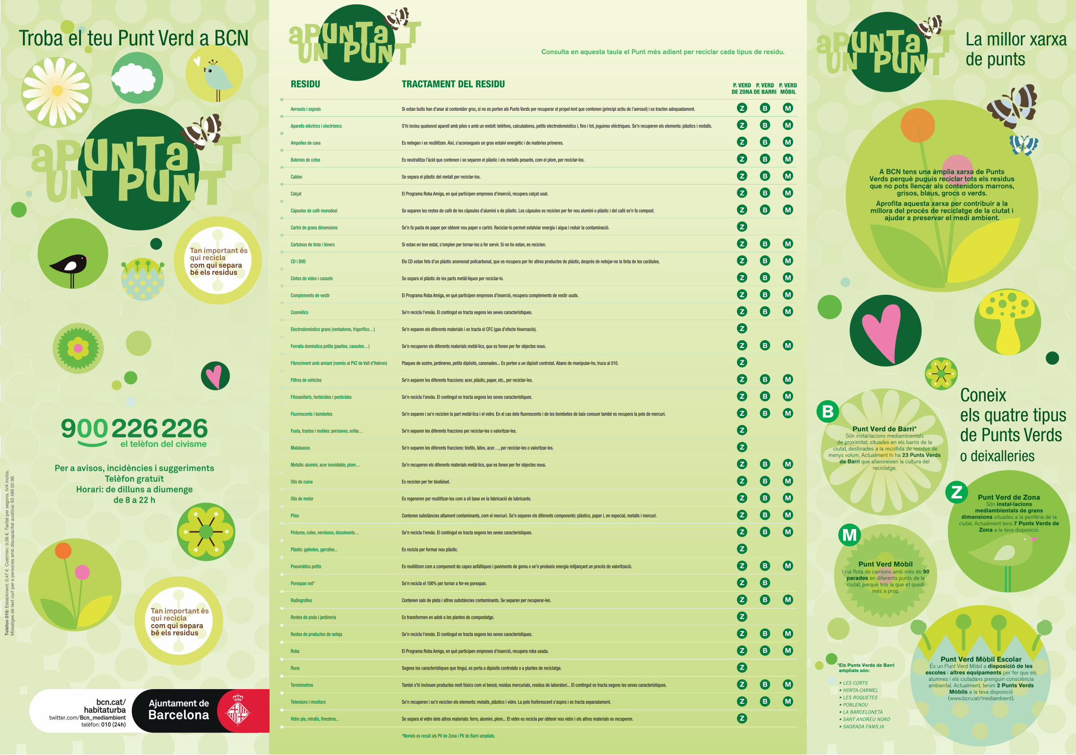
Consulta en aquesta taula el Punt més adient per reciclar cada tipus de residu.
Per a avisos, incidències i suggeriments Telèfon gratuït
Horari: de dilluns a diumenge de 8 a 22 h
Tel
èfo
n 01
0: E
stab
limen
t: 0
,47
€. C
ost/
min
: 0,0
6 €.
Tar
ifat
per
seg
ons.
IVA
incl
òs.
Mis
satg
es d
e te
xt c
urt
per
a p
erso
nes
amb
dis
cap
acita
t au
diti
va: 9
3 48
9 00
98.
bcn.cat/habitaturba
twitter.com/ Bcn_mediambienttelèfon: 010 (24h)
*Els Punts Verds de Barri ampliats són:
• LES CORTS • HORTA-CARMEL• LES ROQUETES• POBLENOU• LA BARCELONETA • SANT ANDREU NORD• SAGRADA FAMÍLIA
A BCN tens una àmplia xarxa de Punts Verds perquè puguis reciclar tots els residus que no pots llençar als contenidors marrons,
grisos, blaus, grocs o verds.Aprofita aquesta xarxa per contribuir a la
millora del procés de reciclatge de la ciutat i ajudar a preservar el medi ambient.
ApUNTA Tun PUNT
Punt Verd de Barri*Són instal·lacions mediambientals
de proximitat, situades en els barris de la ciutat, destinades a la recollida de residus de
menys volum. Actualment hi ha 23 Punts Verds de Barri que afavoreixen la cultura del
reciclatge.
Punt Verd Mòbil Una flota de camions amb més de 90
parades en diferents punts de la ciutat, perquè triïs la que et quedi
més a prop.
Punt Verd de ZonaSón instal·lacions
mediambientals de grans dimensions situades a la perifèria de la
ciutat. Actualment tens 7 Punts Verds de Zona a la teva disposició.
Punt Verd Mòbil Escolar És un Punt Verd Mòbil a disposició de les
escoles i altres equipaments per fer que els alumnes i els ciutadans prenguin consciència ambiental. Actualment, tenim 2 Punts Verds
Mòbils a la teva disposició (www.bcn.cat/mediambient).
ApUNTA Tun PUNT
ApUNTA Tun PUNT
Troba el teu Punt Verd a BCN La millor xarxade punts
Coneixels quatre tipusde Punts Verdso deixalleries
RESIDU TRACTAMENT DEL RESIDU P. VERD P. VERD P. VERD DE ZONA DE BARRI MÒBIL
Aerosols i esprais Si estan buits han d'anar al contenidor groc, si no es porten als Punts Verds per recuperar el propel·lent que contenen (principi actiu de l'aerosol) i es tracten adequadament. Z B M
Aparells elèctrics i electrònics S’hi inclou qualsevol aparell amb piles o amb un endoll: telèfons, calculadores, petits electrodomèstics i, �ns i tot, joguines elèctriques. Se’n recuperen els elements: plàstics i metalls. Z B M
Ampolles de cava Es netegen i es reutilitzen. Així, s’aconsegueix un gran estalvi energètic i de matèries primeres. Z B M
Bateries de cotxe Es neutralitza l’àcid que contenen i se separen el plàstic i els metalls pesants, com el plom, per reciclar-los. Z B M
Cables Se separa el plàstic del metall per reciclar-los. Z B M
Calçat El Programa Roba Amiga, en què participen empreses d’inserció, recupera calçat usat. Z B M
Càpsules de cafè monodosi Se separen les restes de cafè de les càpsules d’alumini o de plàstic. Les càpsules es reciclen per fer nou alumini o plàstic i del cafè se’n fa compost. Z B M
Cartró de grans dimensions Se’n fa pasta de paper per obtenir nou paper o cartró. Reciclar-lo permet estalviar energia i aigua i reduir la contaminació. Z
Cartutxos de tinta i tòners Si estan en bon estat, s’omplen per tornar-los a fer servir. Si no ho estan, es reciclen. Z B M
CD i DVD Els CD estan fets d’un plàstic anomenat policarbonat, que es recupera per fer altres productes de plàstic, després de netejar-ne la tinta de les caràtules. Z B M
Cintes de vídeo i cassets Se separa el plàstic de les parts metàl·liques per reciclar-lo. Z B M
Complements de vestir El Programa Roba Amiga, en què participen empreses d’inserció, recupera complements de vestir usats. Z B M
Cosmètics Se’n recicla l’envàs. El contingut es tracta segons les seves característiques. Z B M
Electrodomèstics grans (rentadores, frigorí�cs…) Se’n separen els diferents materials i es tracta el CFC (gas d’efecte hivernacle). Z
Ferralla domèstica petita (paelles, cassoles…) Se’n recuperen els diferents materials metàl·lics, que es fonen per fer objectes nous. Z B M
Fibrociment amb amiant (només al PVZ de Vall d’Hebron) Plaques de sostre, jardineres, petits dipòsits, canonades... Es porten a un dipòsit controlat. Abans de manipular-ho, truca al 010. Z
Filtres de vehicles Se’n separen les diferents fraccions: acer, plàstic, paper, etc., per reciclar-les. Z B M
Fitosanitaris, herbicides i pesticides Se’n recicla l’envàs. El contingut es tracta segons les seves característiques. Z B M
Fluorescents i bombetes Se’n separen i se’n reciclen la part metàl·lica i el vidre. En el cas dels �uorescents i de les bombetes de baix consum també es recupera la pols de mercuri. Z B M
Fusta, trastos i mobles: persianes, sofàs… Se’n separen les diferents fraccions per reciclar-les o valoritzar-les. Z
Matalassos Se’n separen les diferents fraccions: tèxtils, làtex, acer…, per reciclar-les o valoritzar-les. Z
Metalls: alumini, acer inoxidable, plom… Se’n recuperen els diferents materials metàl·lics, que es fonen per fer objectes nous. Z B M
Olis de cuina Es reciclen per fer biodièsel. Z B M
Olis de motor Es regeneren per reutilitzar-los com a oli base en la fabricació de lubricants. Z B M
Piles Contenen substàncies altament contaminants, com el mercuri. Se’n separen els diferents components: plàstics, paper i, en especial, metalls i mercuri. Z B M
Pintures, coles, vernissos, dissolvents… Se’n recicla l’envàs. El contingut es tracta segons les seves característiques. Z B M
Plàstic: galledes, garrafes... Es recicla per formar nou plàstic. Z
Pneumàtics petits Es reutilitzen com a component de capes asfàltiques i paviments de goma o se’n produeix energia mitjançant un procés de valorització. Z B M
Porexpan net* Se’n recicla el 100% per tornar a fer-ne porexpan. Z B
Radiogra�es Contenen sals de plata i altres substàncies contaminants. Se separen per recuperar-les. Z B M
Restes de poda i jardineria Es transformen en adob a les plantes de compostatge. Z
Restes de productes de neteja Se’n recicla l’envàs. El contingut es tracta segons les seves característiques. Z B M
Roba El Programa Roba Amiga, en què participen empreses d’inserció, recupera roba usada. Z B M
Runa Segons les característiques que tingui, es porta a dipòsits controlats o a plantes de reciclatge. Z
Termòmetres També s’hi inclouen productes molt tòxics com el benzè, residus mercurials, residus de laboratori... El contingut es tracta segons les seves característiques. Z B M
Televisors i monitors Se’n recuperen i se’n reciclen els elements: metalls, plàstics i vidre. La pols fosforescent s’aspira i es tracta separadament. Z B M
Vidre pla, miralls, �nestres... Se separa el vidre dels altres materials: ferro, alumini, plom... El vidre es recicla per obtenir nou vidre i els altres materials es recuperen. Z
*Només es recull als PV de Zona i PV de Barri ampliats.
Tan important ésqui reciclacom qui separabé els residus
Tan important ésqui reciclacom qui separabé els residus

General Mitre, 28-36dimarts de 8.30 a 14.00 h
Jardins de Manuel J. Arnalot (Av. del Jordà, 29)dimarts de 16.00 a 19.30 h
Mercat de les CortsTrav. de les Corts, 229dijous de 8.30 a 14.00 h
Joan Güell, 30 (entre Miquel Àngel i Rajolers) dimecres de 16.00 a 19.30 h
Can Basilio
Cartellà
Mercat de la Unió - Poblenou (Bilbao, 25)
Bacardí
Horta-Carmel
Passatge de Tossa / Lisboadimarts de 8.30 a 14.00 h
Pedrell, 58dimecres de 8.30 a 14.00 h
Turó de la Peira
Les Roquetes
Ciutat Meridiana
Darnius / Espinaugadijous de 8.30 a 14.00 h
CAP Ciutat MeridianaSant Feliu de Codines / Av. de Vallbonadilluns de 16.00 a 19.30 h
Nova Esquerra de l’Eixample
Biscaia / Av. Meridianadivendres de 8.30 a 14.00 h
Taulat/Provençalsdimarts de 16.00 a 19.30 h
Travessera de Dalt / Alegre de Daltdilluns de 8.30 a 14.00 h
Vallvidrera
Rep. Argentina, 108-110(al costat del metro de Vallcarca)dimarts de 8.30 a 14.00 h
Mercat de Sant Antoni (Urgell/Manso)divendres de 8.30 a 14.00 h
Pl. del Doctor Letamendi, 24(costat muntanya)dimecres de 16.00 a 19.30 h
Mercat de Sta. Caterina (Francesc Cambó, 12) dissabte de 8.30 a 14.00 h
Mercat de la Barceloneta (Atlàntida, 49)dijous de 8.30 a 14.00 h
Jardins de Can Senillosa (Fontcoberta, 5)dimecres de 16.00 a 19.30 h
Mercat de l’Estrella (Providència/Sardenya)dimecres de 8.30 a 14.00 h
Rbla. de Guipúscoa / Bac de Rodadilluns de 16.00 a 19.30 h
Rbla. del Poblenou / Sancho de Áviladimarts de 16.00 a 19.30 h
Pl. de les Madres de Mayo (amb passeig de Verdun)divendres de 8.30 a 14.00 h
Mercat de la Guineueta (Pg. de Valldaura, 186)dissabte de 8.30 a 14.00 h
Cardenal Reig / Sant Ramon Nonatdijous de 16.00 a 19.30 h
Mercat de la Vall d’Hebron (Pg. de la Vall d’Hebron, 128)dijous de 8.30 a 14.00 h
Pl. de la Font Castellana (Av. de la Mare de Déu de Montserrat / Francesc Alegre)dijous de 16.00 a 19.30 h
Mercat de Galvany (Santaló, 65)divendres de 8.30 a 14.00 h
Turó Parc (Av. de Pau Casals, 17)dilluns de 16.00 a 19.30 h
Joan Sales / Poesiadilluns de 16.00 a 19.30 h
Sant Martí de Provençals
Pl. de Sarrià (amb Major de Sarrià)
de
Pl. de la Bonanova (amb pg. de la Bonanova)
Mercat de St. Gervasi(Pl. de Frederic Soler)
Pl. de Lesseps Pl. del Virrei Amat (amb av. de Borbó)
Numància / Nau de Sta. Maria
Pl. del Congrés Eucarístic, 10
Pl. de la Concòrdia (amb Deu i Mata)
Pl. de Maragall, 14
Rbla. de l’Onze de Setembre /Mercat de Felip II(Olesa/Garcilaso)
Plaça del Guinardó, 10
Pl. de la Revolució (amb Terol) Lepant/TaxdirtAv. de Madrid / Av. de Carles III
Pl. de l’Olivereta (Bacardí, 33) Pg. de Sant Joan / Indústria
Indústria / Pg. de MaragallRbla. de Badal / SantsProvença / Rbla. de Catalunya
Pg. de Sant Joan / RossellóPg. de Sant Antoni / Galileu
(Casanova/Mallorca)
Rbla. de Prim / Guipúscoa
Badal/Quetzal
Mercat d’Hostafrancs (Vilardell, 33)
Mercat de St. Martí(Puigcerdà/Andrade)Pl. de Sara Bernhardt
(amb Gran Via de les Corts Catalanes)Casp/Bruc
Mercat de la Marina(Pl. de la Marina de Sants)
Av. del Paral·lel / Jaume FabraRbla. de Prim / Cristóbal de Moura
Marina/Almogàvers
Pl. de Sant Miquel
Drassanes / Portal de Sta. Madrona
Pl. del Duc de Medinacelli (amb Ample) Av. d’Icària / Arquitecte Sert
Sant Andreu Nord
Les Corts
dijous de 16.00 a 19.30 h
Pl. dels Àngels (amb Montalegre)
Pl. de la Farga (amb Almeria)
Santuari, 27 (davant del centre cívic El Carmel)
Diagonal Mar (Av. Diagonal / Llull)
Poblenou FòrumLa Barceloneta
La Bordeta
Mercat de la Trinitat, (Chafarinas entre Via Favència i la Fosca) dilluns de 8.30 a 14.00 h
Pl. de la Trinitat (amb Galícia)
Via Júlia / Francesc Layret
Pl. d’Or�la (amb Segre)
São Paulo / Posoltega
Mercat del Bon Pastor
Pl. Verda de la Prosperitat (Tissó/Vinyar)
Deu i Mata / Numància (dav. de la pl. de Can Rosés)dimarts de 16.00 a 19.30 h
Pl. d’Espronceda (amb Perú)divendres de 16.00 a 19.30 h
Mercat de Provençals (Treball/Menorca)dissabte de 8.30 a 14.00 h
Escorial / Pi i Margall (dav. pl. de Joanic)dissabte de
Pl. de la Pau (amb Concili de Trento)dimarts de
Pg. de Sant Joan
Trobael teu Punt!!!
Aquests són els Punts Verds o deixalleries de la ciutat. Localitza els que et
convinguin més i recicla còmodament.
Direccióa direcció
CollserolaCollserola, 2, amb passeig de la Vall d’Hebron, Rda. De Dalt, Sortida 6
FòrumAvda. del Litoral, 115, Rda. Litoral, lateral mar, Sortida 24, passat Josep Pla
Les Corts - PedralbesAvda. d’Esplugues amb Gran Capità
MontjuïcFoc, 56, cantonada amb Cobalt
Sant AndreuCaracas, 46, entre Potosí i Tucumán
Vall d’HebronAvda. de l’Estat de Catalunya, 23, amb Camí de Can Travi
VallbonaCastelladrall, 14
ClotParc del Clot, Escultors Claperós davant de Coronel SanfeliuVallvidreraReis Catòlics al costat de l’escola NabíGal·la PlacídiaPl. de Gal·la Placídia amb Travessera de GràciaHorta - GuinardóMas Casanovas davant de l’entrada del pàrquing de l’Hospital de Sant PauHorta - CarmelDante Alighieri amb C/ de les LletresTuró de la PeiraPg. de la Peira, 1Les RoquetesC. de les Torres amb AiguablavaCiutat MeridianaCostabona, 4, al costat del Mercat de Ciutat MeridianaSant AndreuSant Ildefons cantonada amb Rovira VirgiliSant Andreu NordPl. de Miquel Casablancas i Joanico amb BartrinaPoblenouCarmen Amaya amb LlacunaLa Barceloneta***Pg. de Salvat Papasseit, 1 al costat de la Fàbrica del Sol
Poble-secPl. de les Tres Xemeneies a la banda de Palaudàries
Folch i TorresPl. de Josep M. Folch i Torres amb Reina Amàlia
Sant Martí de ProvençalsAndrade, 154
Can Basilio (col·laborador)**Jaume Giralt, 49, baixos
Les CortsNicaragua amb Marquès de Sentmenat
BacardíJardins de Bacardí, Comandant Benitez amb Travessera de les Corts
Sagrada FamiliaLepant, 281-283
Fort PiencAlí Bei cantonada amb Sicília
La BordetaJardins de Celestina Vigneaux amb Corral
Nova Esquerra de l’EixampleJardins de Montserrat, Còrsega amb Rocafort
Tabuenca (col·laborador)*Guilleries, 24
De DILLUNS a DIVENDRES DISSABTES i DIUMENGES FESTIUS De 8 a 18:30h De 9 a 13h Tancat
De DILLUNS a DISSABTE* DIUMENGES i FESTIUS De 8:30 a 14h i de 16 a 19:30h Tancat
*Tabuenca: de dilluns a divendres, de 8:30 a 13:30h i de 16:00 a 19:00 h, i dissabtes, de 10:00 a 13.00h. Del 24 de juny al 24 de setembre, dissabtes tancat. La setmana següent a la Festa Major de Gràcia el PVC també romandrà tancat.
** Can Basilio: de dilluns a divendres, de 10:00 a 13.30h i de 16:30 a 19:30h, i dissabtes, de 10:00 a 13:30h. Del 24 de juny al 24 de setembre, dissabtes tancat.
*** Previsió de posada en servei: primer trimestre de 2013.

ANNEX: Estudi de viabilitat d'una empresa de reforços de formigó amb materials compostos
- AM73 -
ANNEX 10: COMPROVANT NOM SOCIETAT
DISPONIBLE

ANNEX: Estudi de viabilitat d'una empresa de reforços de formigó amb materials compostos
- AM74 -
ANNEX 11: COMPETIDORS PRIMERA ETAPA
BASF
http://www.basf.es/ecp1/Spain/es/
BASF és l'empresa química líder mundial: The Chemical Company. Oferim
solucions intel·ligents i productes d'alta qualitat als nostres clients.
Les empreses del grup BASF a la Península Ibèrica fabriquen productes químics
per ajudar els seus clients a tenir més èxit en pràcticament qualsevol sector de la
indústria. Actualment, BASF comercialitza a Espanya la seva extensa gamma de
productes a través de set empreses i una joint venture, en què treballen més de
2.000 col·laboradors. Cinc d'elles disposen de centres de producció propis. A
Portugal, comptem amb dues empreses en quatre localitzacions diferents.
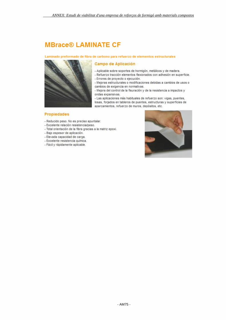
ANNEX: Estudi de viabilitat d'una empresa de reforços de formigó amb materials compostos
- AM75 -
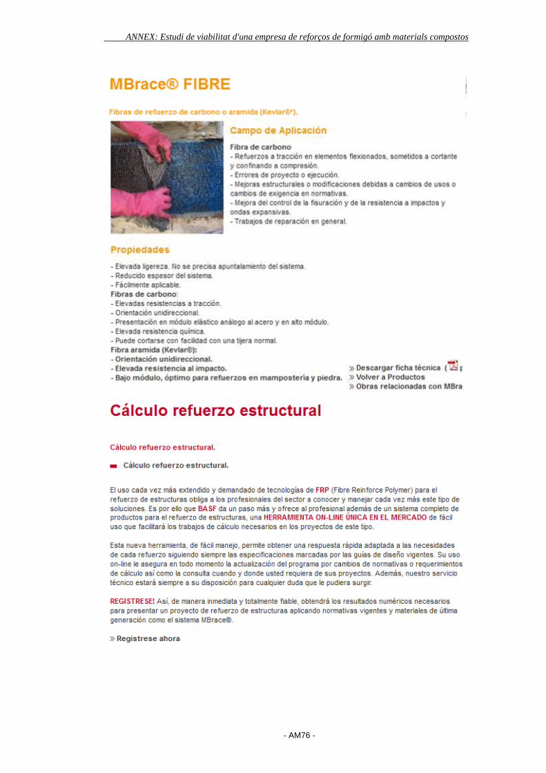
ANNEX: Estudi de viabilitat d'una empresa de reforços de formigó amb materials compostos
- AM76 -
ANNEX: Estudi de viabilitat d'una empresa de reforços de formigó amb materials compostos
- AM77 -
SIKA
http://esp.sika.com/es/group.html
Sika desenvolupa solucions orientades al futur en construccions de primer nivell,
optimitzant els processos dels clients i reduint els seus costos. El ràpid
subministrament de productes innovadors i serveis de qualitat garantida arreu del
món són factors clau de l'èxit, que ha permès a Sika arribar a taxes de
creixement per sobre de la mitjana en mercats difícils i el desembarcament
reeixit en nous mercats.
La divisió de construcció de Sika està repartida en tres unitats de negoci:
Aplicadors
Productors de Formigó
Distribució
Sika té equips tècnics i de vendes específics en contacte directe amb els clients
en cada fase de la construcció. D'aquesta manera s'assegura una qualitat
perfecta i una satisfacció completa.
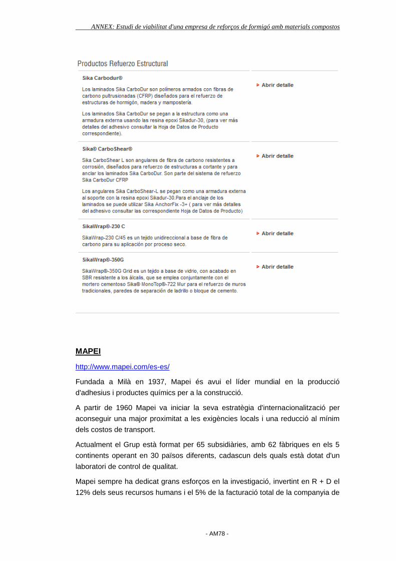
ANNEX: Estudi de viabilitat d'una empresa de reforços de formigó amb materials compostos
- AM78 -
MAPEI
http://www.mapei.com/es-es/
Fundada a Milà en 1937, Mapei és avui el líder mundial en la producció
d'adhesius i productes químics per a la construcció.
A partir de 1960 Mapei va iniciar la seva estratègia d'internacionalització per
aconseguir una major proximitat a les exigències locals i una reducció al mínim
dels costos de transport.
Actualment el Grup està format per 65 subsidiàries, amb 62 fàbriques en els 5
continents operant en 30 països diferents, cadascun dels quals està dotat d'un
laboratori de control de qualitat.
Mapei sempre ha dedicat grans esforços en la investigació, invertint en R + D el
12% dels seus recursos humans i el 5% de la facturació total de la companyia de
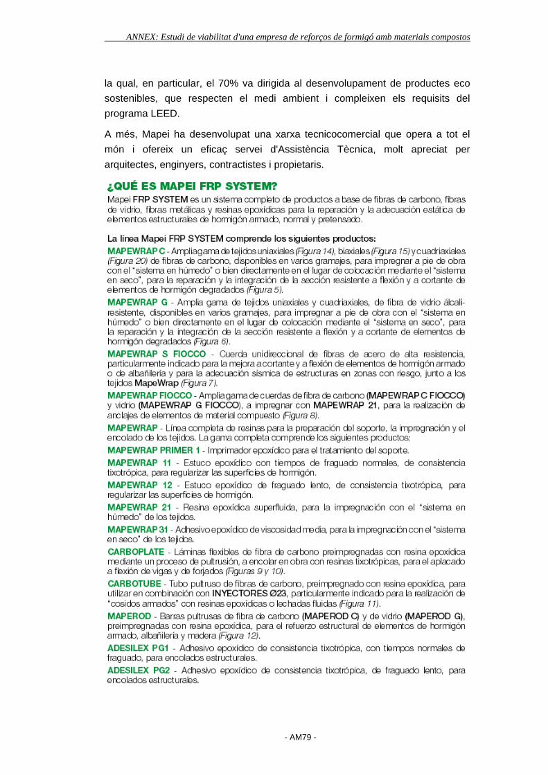
ANNEX: Estudi de viabilitat d'una empresa de reforços de formigó amb materials compostos
- AM79 -
la qual, en particular, el 70% va dirigida al desenvolupament de productes eco
sostenibles, que respecten el medi ambient i compleixen els requisits del
programa LEED.
A més, Mapei ha desenvolupat una xarxa tecnicocomercial que opera a tot el
món i ofereix un eficaç servei d'Assistència Tècnica, molt apreciat per
arquitectes, enginyers, contractistes i propietaris.

ANNEX: Estudi de viabilitat d'una empresa de reforços de formigó amb materials compostos
- AM80 -
BETEC
http://www.betec.es/home
Els Productes BETEC compten amb més de trenta anys d'experiència. BETEC
s'ha especialitzat en la investigació, desenvolupament, fabricació, distribució i
posada en obra de morters especials i productes químics per a la construcció.
Sempre a l'avantguarda entre les empreses del sector, BETEC ha estat pionera
en la fabricació a Espanya de morters d'altes resistències sense retracció i de
tota una gamma de productes auxiliars per a la reparació del formigó, que van
millorar ostensiblement les tècniques de construcció emprades i aconseguint que
BETEC avui dia, sigui capaç d'aportar les solucions tecnològicament més
avançades per a l'obra civil, l'edificació, el manteniment, la indústria i la
rehabilitació.
Des del 12 de maig de l'any 2.010 BETEC passa a formar part de Propamsa
SAU, empresa del Grup Cementos Molins, com la divisió de productes especials.
Tant des Propamsa com des BETEC, l'objectiu principal és la satisfacció dels
nostres clients, garantint les solucions més avançades i anticipant-nos a les
seves necessitats.
Per això, comptem amb una àmplia gamma de productes i solucions que
compleixen els més alts estàndards per qualitat i tecnologia. De la unió
d'esforços de les dues empreses pretenem oferir al mercat una major gamma de
productes i un millor servei.

ANNEX: Estudi de viabilitat d'una empresa de reforços de formigó amb materials compostos
- AM81 -
CPE
http://www.consultoracpe.com/refuerzos_fibra.php
CPE compta amb un departament dedicat a la cada vegada mes important
especialització de reforços d'estructures existents emprant làmines de fibra de
carboni i resines amb base epoxídica fabricats per l'empresa SIKA .... Dins
d'aquest departament disposes de personal especialitzat en el càlcul d'aquest
tipus de reforços així com d'instal·ladors homologats per l'empresa
subministradora dels reforços.
En tractar-se d'un tipus de reforços de relativament jove implantació en el mercat
de les rehabilitacions a nivell nacional, es requereix per a la correcta utilització de
la supervisió dels treballs per part d'un grup d'enginyers qualificat i amb
experiència, i això és precisament el que CPE ofereix, avalats per la seva
experiència en l'àmbit del càlcul estructural.
El correcte ús d'aquests elements, comporta l'estudi expert de cada projecte, per
tal de poder valorar l'adequació o no d'aquesta tipologia de reforç per a cada cas
concret, ja que com sempre en estructures no es tracta només de calcular el
reforç necessari sinó de saber per a cada situació especial, que classe de reforç
s'adapta millor tant des del punt de vista econòmic, com de l'estructural i
arquitectònic.
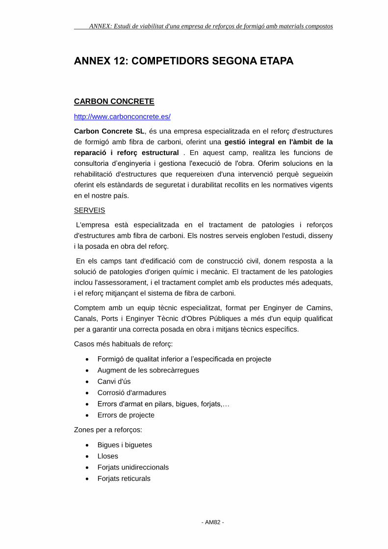
ANNEX: Estudi de viabilitat d'una empresa de reforços de formigó amb materials compostos
- AM82 -
ANNEX 12: COMPETIDORS SEGONA ETAPA
CARBON CONCRETE
http://www.carbonconcrete.es/
Carbon Concrete SL, és una empresa especialitzada en el reforç d'estructures
de formigó amb fibra de carboni, oferint una gestió integral en l'àmbit de la
reparació i reforç estructural . En aquest camp, realitza les funcions de
consultoria d’enginyeria i gestiona l'execució de l'obra. Oferim solucions en la
rehabilitació d'estructures que requereixen d'una intervenció perquè segueixin
oferint els estàndards de seguretat i durabilitat recollits en les normatives vigents
en el nostre país.
SERVEIS
L'empresa està especialitzada en el tractament de patologies i reforços
d'estructures amb fibra de carboni. Els nostres serveis engloben l'estudi, disseny
i la posada en obra del reforç.
En els camps tant d'edificació com de construcció civil, donem resposta a la
solució de patologies d'origen químic i mecànic. El tractament de les patologies
inclou l'assessorament, i el tractament complet amb els productes més adequats,
i el reforç mitjançant el sistema de fibra de carboni.
Comptem amb un equip tècnic especialitzat, format per Enginyer de Camins,
Canals, Ports i Enginyer Tècnic d'Obres Públiques a més d'un equip qualificat
per a garantir una correcta posada en obra i mitjans tècnics específics.
Casos més habituals de reforç:
Formigó de qualitat inferior a l’especificada en projecte
Augment de les sobrecàrregues
Canvi d'ús
Corrosió d'armadures
Errors d'armat en pilars, bigues, forjats,…
Errors de projecte
Zones per a reforços:
Bigues i biguetes
Lloses
Forjats unidireccionals
Forjats reticurals

ANNEX: Estudi de viabilitat d'una empresa de reforços de formigó amb materials compostos
- AM83 -
Pilars
L'ús de fibra de carboni com a substitutiu de l'acer, ens aporta avantatges com
l'absència de corrosió, una mínima càrrega morta a l'estructura, curt temps
d'intervenció i afectació a l'obra. Al ser un producte molt lleuger, permet
manipular-lo amb les mans i s'adhereix sense necessitat d' apuntalar, si bé les
seves propietats són clarament superiors a l'acer tradicional. La reducció en el
cost global d'aplicació d'un reforç de fibra de carboni (producte més mà d'obra i
maquinària) es situa entorn al 30-40% davant d'un reforç tradicional.
NOVAPOX
http://www.novapox.com/
NOVAPOX és una societat del sector de la construcció creada al març de 1997,
fruit de l'associació d'un grup de professionals amb una dilatada experiència de
més de 20 anys en el camp de les aplicacions tècniques, principalment en el
camp de les reparacions i reforços estructurals.
La missió de NOVAPOX és ser una empresa de rehabilitació d'edificis líder al
sector, oferint la màxima qualitat de treball en totes les àrees: equip tècnic,
administració, producció i direcció general, amb una visió molt clara, ser una
empresa capdavantera en el món de la rehabilitació i, concretament, en el món

ANNEX: Estudi de viabilitat d'una empresa de reforços de formigó amb materials compostos
- AM84 -
de la química aplicada a la construcció, fent servir tècniques innovadores i, al
mateix temps, mantenint l'essència d'una empresa de rehabilitació tradicional.
Posem a disposició dels nostres clients una Gestió Integral del projecte facilitant
un desenvolupament "claus en mà" del mateix a través de la interlocució amb els
nostres tècnics.
El nostre equip tècnic d'Arquitectes, Arquitectes Tècnics i Enginyers podran
assegurar la qualitat al llarg de tot el projecte responent a les necessitats que el
client ens sol · liciti o bé prenent iniciativa i decisions sobre la intervenció puntual
o la rehabilitació total a l'edifici. Els mateixos tècnics, arquitectes i enginyers,
coordinen i supervisen les obres des de l'inici de l'encàrrec fins al final realitzant:
Anàlisi i diagnòstic de conservació de l'edifici.
Redacció de documentació tècnica. Projecte.
Confecció de pressupost de les obres.
Sol·licitud de permisos d'obra i tramitació de subvencions.
Execució del projecte.
Lliurament i liquidació d'obra.
ORION GRUPO
http://www.oriongrupo.com/default.asp
Amb més de 18 anys dedicats al sector de la reparació, reforç i
impermeabilització d'estructures de formigó, Orion Reparació estructural SL és
una de les empreses pioneres en aquest camp.
Amb infinitat d'obres realitzades en tota la geografia nacional Orion pot ser
considerada l'empresa líder en la rehabilitació d'obres d’edificació, obra pública o
enginyeria civil.

ANNEX: Estudi de viabilitat d'una empresa de reforços de formigó amb materials compostos
- AM85 -
La recerca de la millora contínua i la col · laboració amb els nostres clients, fan
de la nostra empresa el soci de referència per als clients privats o les
administracions públiques, aportant en cada cas la solució més òptima per a
cada problema.
Tècnicament avançats
Dins la política d'Orion sempre aquesta la incorporació de les més modernes
tecnologies al nostre servei, que ens aportin una diferenciació de la competència
i més ens ajudin en la millora de la competitivitat de l'empresa.
Amb aquesta finalitat Orion ha estat capaç d'incorporar en els seus sistemes de
producció la maquinària més moderna i els sistemes de treball més avançats.
Per tot això som líders en reforços a base de fibra de carboni o aramida,
protecció catòdica d'estructures de formigó, restauració i rehabilitació d'edificis
històrics o la solució de patologies estructurals.
Per aconseguir uns objectius de satisfacció del client òptims i uns nivells de
seguretat en obra superiors hem implantat els sistemes de qualitat i seguretat
basats en les normes internacionals ISO 9001:2008 i OSHAS 18001:2007 sent
empresa certificada en ambdues normes.
Tecnologia al seu servei
Dins de la política de l'empresa, s'ha primat la incorporació de totes aquelles
unitats de negoci que aportessin valor afegit a l'empresa, de manera que
aquestes àrees de negoci en aquests moments suposen el major percentatge de
facturació de l'empresa.
L'especialització en tot tipus de reforços, l'execució de substitució d'aparells de
suport en ponts, la incorporació de diferents sistemes de protecció d'estructures,
etc. fan que Orion es trobi a l'avantguarda en les tècniques de reparació, reforç,
impermeabilització i protecció d'estructures.
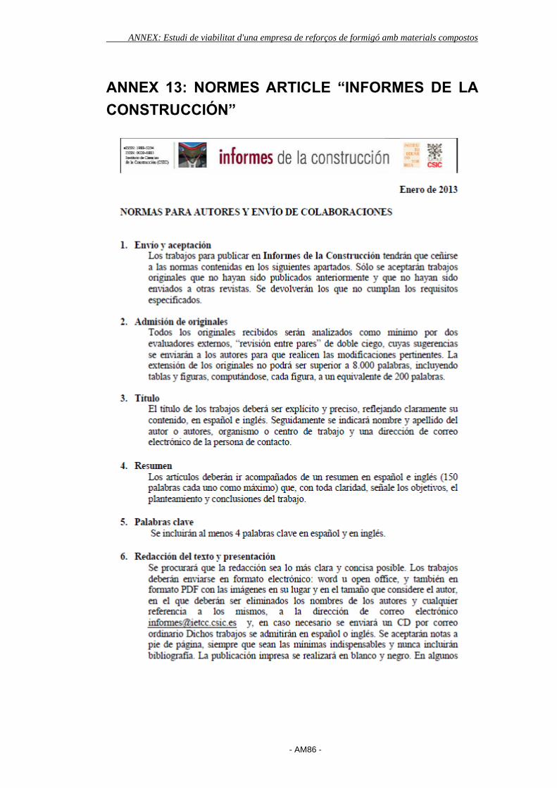
ANNEX: Estudi de viabilitat d'una empresa de reforços de formigó amb materials compostos
- AM86 -
ANNEX 13: NORMES ARTICLE “INFORMES DE LA
CONSTRUCCIÓN”
ANNEX: Estudi de viabilitat d'una empresa de reforços de formigó amb materials compostos
- AM87 -
ANNEX: Estudi de viabilitat d'una empresa de reforços de formigó amb materials compostos
- AM88 -
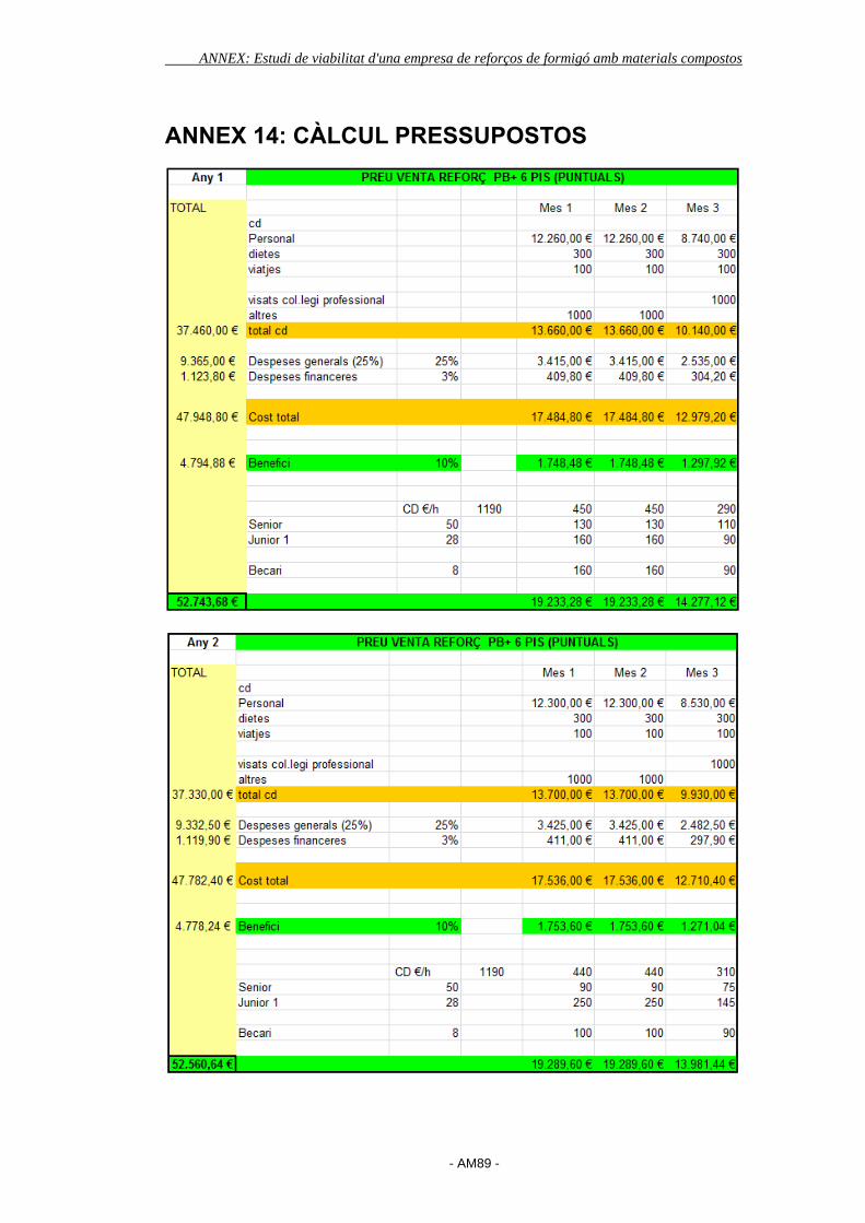
ANNEX: Estudi de viabilitat d'una empresa de reforços de formigó amb materials compostos
- AM89 -
ANNEX 14: CÀLCUL PRESSUPOSTOS
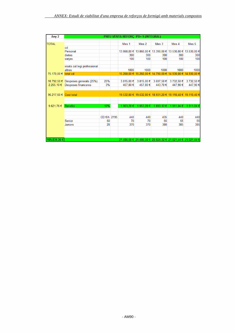
ANNEX: Estudi de viabilitat d'una empresa de reforços de formigó amb materials compostos
- AM90 -

ANNEX: Estudi de viabilitat d'una empresa de reforços de formigó amb materials compostos
- AM91 -
ANNEX 15: PLANIFICACIÓ PROJECTE
Per tal de realitzar al planificació d’aquest projecte s’ha utilitzat l’eina d’ofimàtica
Microsoft Project. El fet de fer aquesta planificació ha estat molt útil per assignar
temporalment les tasques i poder fer un seguiment en tot moment de les tasques
pendents.
Així doncs ens les següent pàgines es mostra el diagrama de Gantt del projecte
amb el temps assignat a cada tasca.