Embed Size (px)
Citation preview

User manual
M2306 & M2307, Lift control module
Please select your language
English Suomi
Français Norsk
Polski Svenska
Italiano Dansk
Español Pусский
Português 简体中文
Čeština Deutsch
Slovenčina Nederlands
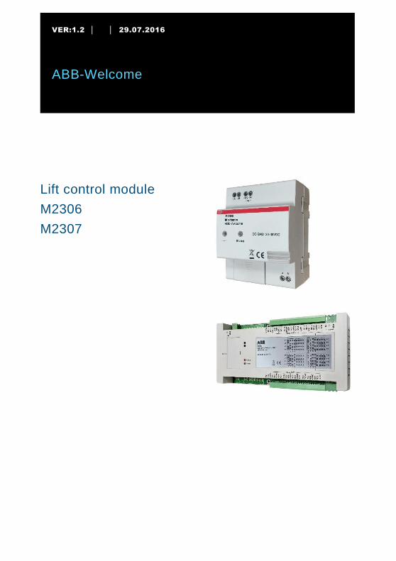
VER:1.2 │ │ 29.07.2016
ABB-Welcome
Pos: 2 /Di nA4 - Anleitung en Online/Inhalt /KN X/D oorEntr y/83220- AP- xxx/Titelbl att - 83220-AP- xxx - ABB @ 19\mod_1323249806476_15.docx @ 111084 @ @ 1
Lift control module
M2306
M2307
=== Ende der Liste für Textmar ke Cover ===
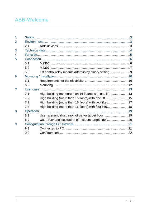
ABB-Welcome
| — 2 —
Pos: 4 /Busch-Jaeger (Neus truktur)/M odul-Str uktur/Online-Dokumentation/Inhal tsverzeichnis (--> Für alle D okumente <--)/Inhaltsverzeichnis @ 19\mod_1320649044386_15.docx @ 109653 @ @ 1
1 Safety ............................................................................................................ 3 2 Environment .................................................................................................. 3
2.1 ABB devices ................................................................................. 3 3 Technical data ............................................................................................... 4 4 Function ......................................................................................................... 5 5 Connection .................................................................................................... 6
5.1 M2306 ........................................................................................... 6 5.2 M2307 ........................................................................................... 7 5.3 Lift control relay module address by binary setting ....................... 9
6 Mounting / Installation .................................................................................. 10 6.1 Requirements for the electrician ................................................. 10 6.2 Mounting ..................................................................................... 12
7 User case .................................................................................................... 13 7.1 High building (no more than 16 floors) with one lift ..................... 13 7.2 High building (more than 16 floors) with one lift .......................... 15 7.3 High building (more than 16 floors) with two lifts ........................ 17 7.4 High building (more than 16 floors) with four lifts ........................ 18
8 Operation ..................................................................................................... 19 8.1 User scenario illustration of visitor target floor ............................ 19 8.2 User Scenario Illustration of resident target floor ........................ 20
9 Configuration through PC software .............................................................. 21 9.1 Connected to PC ........................................................................ 21 9.2 Configuration .............................................................................. 22
=== Ende der Liste für Textmar ke TOC ===

ABB-Welcome
Pos: 6 /Busch-Jaeger (Neus truktur)/M odul-Str uktur/Online-Dokumentation/Überschriften (--> Für alle Dokumente <--)/1. Ebene/S - T/Sicherheit @ 18\mod_1302612791790_15.docx @ 103357 @ 1 @ 1
1 Safety Pos : 7 /Busch-Jaeger (Neus truktur)/M odul-Str uktur/Online-Dokumentation/Sicherheit (--> Für all e D okumente <--)/Warnhi nweise/Sicherheit - 230 V @ 18\mod_1302606816750_15.docx @ 103308 @ @ 1
Warning
Electric voltage!
Risk of death and fire due to electrical voltage of 100-240 V.
– Work on the 100-240 V supply system may only be performed by
authorized electricians!
– Disconnect the mains power supply prior to installation and/or
disassembly!
Pos: 10 /Busch-Jaeg er (Neustr uktur)/Modul- Struktur /Online-Dokumentati on/Überschriften (--> Für alle D okumente <--)/1. Ebene/U - Z/U mwelt @ 18\mod_1302614158967_15.docx @ 103383 @ 1 @ 1
2 Environment Pos : 11 /Busch-Jaeg er (Neustr uktur)/Modul- Struktur /Online-Dokumentati on/U mwel t (--> Für alle D okumente <--)/Hinweise/Hi nweis - U mwelt - Hinweis Elektrog eräte @ 18\mod_1302763973434_15.docx @ 103500 @ @ 1
Consider the protection of the environment!
Used electric and electronic devices must not be disposed of with
household waste.
– The device contains valuable raw materials that can be recycled.
Therefore, dispose of the device at the appropriate recycling
facility.
Pos: 12 /DinA4 - Anl eitungen Onli ne/Ueberschrif ten/2./ABB Geraete @ 19\mod_1323162843832_15.docx @ 110875 @ 2 @ 1
2.1 ABB devices Pos : 13 /Busch-Jaeg er (Neustr uktur)/Modul- Struktur /Online-Dokumentati on/U mwel t (--> Für alle D okumente <--)/Hinweise/Hi nweis - U mwelt - ABB El ektr ogeräte @ 19\mod_1323162745839_15.docx @ 110867 @ @ 1
All packaging materials and devices from ABB bear the markings and test seals for
proper disposal. Always dispose of the packaging material and electric devices and their
components via an authorized collecting depots or disposal companies.
ABB products meet the legal requirements, in particular the laws governing electronic
and electrical devices and the REACH ordinance.
(EU-Directive 2002/96/EG WEEE and 2002/95/EG RoHS)
(EU-REACH ordinance and law for the implementation of the ordinance (EG)
No.1907/2006)
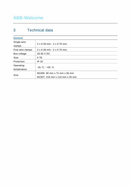
ABB-Welcome
3 Technical data Pos : 14 /Busch-Jaeg er (Neustr uktur)/Modul- Struktur /Online-Dokumentati on/Technische Daten/Di mmer/Technische Daten - 6591 U- 101 @ 23\mod_1333089085280_15.docx @ 207039 @ @ 1
General
Single-wire
clamps 2 x 0.28 mm - 2 x 0.75 mm;
Fine-wire clamps 2 x 0.28 mm - 2 x 0.75 mm;
Bus voltage 20-30 V DC
Size 4 TE
Protection IP 20
Operating
temperature -25 °C - +55 °C
Size M2306: 90 mm x 72 mm x 65 mm
M2307: 216 mm x 110 mm x 45 mm

ABB-Welcome
Pos: 15 /Busch-Jaeg er (Neustr uktur)/Modul- Struktur /Online-Dokumentati on/Steuermodul e - Onli ne-D okumentation (--> Für all e D okumente <--)/++++++++++++ Seitenumbruch ++++++++++++ @ 9\mod_1268898668093_0.docx @ 52149 @ @ 1
4 Function Pos : 22 /Busch-Jaeg er (Neustr uktur)/Modul- Struktur /Online-Dokumentati on/Überschriften (--> Für alle D okumente <--)/2. Ebene/G - L/Lastarten @ 20\mod_1326269704379_15.docx @ 136905 @ 2 @ 1
The lift control modules include the M adaptor (M2306) and lift control relay module (M2307). These two devices together ensure that lift (elevator) only goes to authorized floor(s). If a resident presses the "unlock" button when receiving a guest's call from the outdoor station, or the authorized user swipes the registered card or enters correct password, the lift (elevator) will automatically go down to the floor where the outdoor station is installed. The lift (elevator) will then go to the dedicated floor where that resident lives. It cannot go to unauthorized floors, even when other buttons are pressed. The configuration should be done through the dedicated configuration software by connecting the M adaptor to a computer.

ABB-Welcome
Pos: 30 /Busch-Jaeg er (Neustr uktur)/Modul- Struktur /Online-Dokumentati on/Überschriften (--> Für alle D okumente <--)/1. Ebene/A - F /Anschluss @ 19\mod_1309248278435_15.docx @ 107413 @ 1 @ 1
5 Connection
5.1 M2306 Pos : 31 /Busch-Jaeg er (Neustr uktur)/Modul- Struktur /Online-Dokumentati on/Anschluss/Di mmer /Anschluss - 6591 U-101 @ 23\mod_1333093920008_15.docx @ 207132 @ @ 1
Fig. 1
No. Function
1 Status
- ON = Connected with the system controller/internal bus
- OFF = Not connected with the system controller/internal bus
- Blinking = Working with the system controller/internal bus
2 - ON = Power on
- OFF = Power off
- Blinking = Working
3 Connect with M2307
4 Power supply
5 Connect with the system controller/internal bus

ABB-Welcome
5.2 M2307 Pos : 31 /Busch-Jaeg er (Neustr uktur)/Modul- Struktur /Online-Dokumentati on/Anschluss/Di mmer /Anschluss - 6591 U-101 @ 23\mod_1333093920008_15.docx @ 207132 @ @ 1
Fig. 2
No. Function
1 Power LED
- ON = Power on
- OFF = Power off
2 Setting LED
- Blinks when working normally
3 Address
Set the module address
The address range is 1-16.Only the left 4 bits are used.
4 Power supply
5 Connect with M2306
6 Connect with the lift controller
ABB-Welcome
Pos: 24 /Busch-Jaeg er (Neustr uktur)/Modul- Struktur /Online-Dokumentati on/Steuermodul e - Onli ne-D okumentation (--> Für all e D okumente <--)/++++++++++++ Seitenumbruch ++++++++++++ @ 9\mod_1268898668093_0.docx @ 52149 @ @ 1

ABB-Welcome
5.3 Lift control relay module address by binary setting
Fig. 3
Installer needs only read the labeling on the lift control module and adjust according to the given position.
Only digits 1-2-3-4 are used.

ABB-Welcome
6 Mounting / Installation Pos : 34 /Busch-Jaeg er (Neustr uktur)/Modul- Struktur /Online-Dokumentati on/Sicherheit (--> Für alle Dokumente <--)/Warnhinweise/Sicherheit - Ni ederspannungs- und 230 V-Leitungen @ 18\mod_1302617821491_15.docx @ 103465 @ @ 1
Warning
Electric voltage!
Risk of death and fire due to electric voltage of 230 V.
– Low-voltage and 230 V cables must not be installed together in a
flush-mounted socket!
In case of a short-circuit there is the danger of a 230 V load on the
low-voltage line.
Pos: 35 /Busch-Jaeg er (Neustr uktur)/Modul- Struktur /Online-Dokumentati on/Sicherheit (--> Für alle Dokumente <--)/Warnhinweise/Sicherheit - Vorgeschaltete Sicherung abschalten @ 20\mod_1326441711467_15.docx @ 137043 @ @ 1
Warning
Electric voltage!
The upstream fuse must be disconnected when working on the lighting
system.
Pos: 36 /Busch-Jaeg er (Neustr uktur)/Modul- Struktur /Online-Dokumentati on/Sicherheit (--> Für alle Dokumente <--)/Warnhinweise/Sicherheit - Fachkenntnisse @ 18\mod_1302774384017_15.docx @ 103564 @ 2 @ 1
6.1 Requirements for the electrician
Warning
Electric voltage!
Install the device only if you have the necessary electrical engineering
knowledge and experience.
• Incorrect installation endangers your life and that of the user of the
electrical system.
• Incorrect installation can cause serious damage to property, such as
a fire.
The minimum necessary expert knowledge and requirements for the
installation are as follows:
• Apply the "five safety rules" (DIN VDE 0105, EN 50110):
1. Disconnect the power;
2. Secure against being reconnected;
3. Ensure there is no voltage;
4. Connect to earth;
5. Cover or barricade adjacent live parts.

ABB-Welcome
• Use suitable personal protective clothing.
• Use only suitable tools and measuring devices.
• Check the type of supply network (TN system, IT system, TT system)
to secure the following power supply conditions (classic connection
to ground, protective earthing, necessary additional measures, etc.).

ABB-Welcome
6.2 Mounting Pos : 38 /Busch-Jaeg er (Neustr uktur)/Modul- Struktur /Online-Dokumentati on/Montage/alle Geräte/Montage - U P-Dosen - D IN 49073- 1 oder geeignetes Aufputzgehaeuse - Ohne D ocvariabl e @ 20\mod_1325766034453_15.docx @ 136593 @ @ 1
The device must only be installed on mounting rails according to DIN EN 50022.
It is highly recommended that M2306 be installed in the lift motor room on the top floor
or the electrical riser, while M2307 should be installed in the lift cabin.
Fig. 4
Fig. 5: Dismantle

ABB-Welcome
7 User case
7.1 High building (no more than 16 floors) with one lift
One M2306 and one M2307
Pos : 41 /Busch-Jaeg er (Neustr uktur)/Modul- Struktur /Online-Dokumentati on/Inbetri ebnahme/Di mmer/Inbetriebnahme - 6591 U-101 @ 19\mod_1311948781023_15.docx @ 108300 @ 222 @ 1
Fig. 6: Topology

ABB-Welcome
Wiring with one M2306 and one M2307
Fig. 7

ABB-Welcome
7.2 High building (more than 16 floors) with one lift
one M2306 and multi (up to 16) M2307
Fig. 8: Topology

ABB-Welcome
Wiring with one M2306 and multi M2307
Fig. 9
Notes:
1.The first mini system controller (M2301) feeds one M2306 and one M2307.
2. An additional M2307 should be locally powered by one mini system controller. Eg. with
(4) M2307 and (1) M2306, 4 mini system controllers are needed.
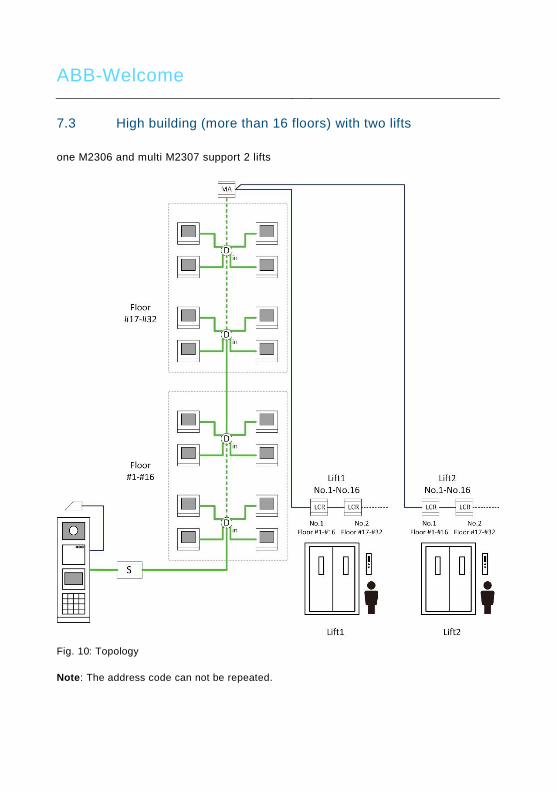
ABB-Welcome
7.3 High building (more than 16 floors) with two lifts
one M2306 and multi M2307 support 2 lifts
Fig. 10: Topology
Note: The address code can not be repeated.

ABB-Welcome
7.4 High building (more than 16 floors) with four lifts
Two M2306 and multi M2307 support 4 lifts
Fig. 11: Topology
Pos: 42 /Busch-Jaeger (Neustruktur)/Modul-Struktur/Online-Dokumentation/Steuermodule - Online-Dokumentation (--> Für alle Dokumente <--)/++++++++++++ Seitenumbruch ++++++++++++ @ 9\mod_1268898668093_0.docx @ 52149 @ @ 1 Note: The address code can not be repeated.

ABB-Welcome
Pos : 43 /Busch-Jaeg er (Neustr uktur)/Modul- Struktur /Online-Dokumentati on/Überschriften (--> Für alle D okumente <--)/1. Ebene/A - F /Bedienung @ 11\mod_1279185541649_15.docx @ 83043 @ 1 @ 1
8 Operation Pos : 44 /Busch-Jaeg er (Neustr uktur)/Modul- Struktur /Online-Dokumentati on/Bedienung/Di mmer/Bedi enung - 6591 U-101 @ 23\mod_1333091293158_15.docx @ 207069 @ @ 1
8.1 User scenario illustration of visitor target floor
Fig. 12
Pos: 42 /Busch-Jaeg er (Neustr uktur)/Modul- Struktur /Online-Dokumentati on/Steuermodul e - Onli ne-D okumentation (--> Für all e D okumente <--)/++++++++++++ Seitenumbruch ++++++++++++ @ 9\mod_1268898668093_0.docx @ 52149 @ @ 1
1.Visitor inputs calling code for
the 12th floor.
2. The resident presses the "unlock" button
at any ABB-Welcome indoor station.
3. The lift will go down to the outdoor station automatically
when visitor enters the lift.
4. Within a set of time (default of 10 minutes), the visitor can only activate the 12th floor. Other floors will not be activated at the same time.
After 10 minutes, the visitor must go to the outdoor station to call the resident again.
5. The visitor reaches the 12th floor.
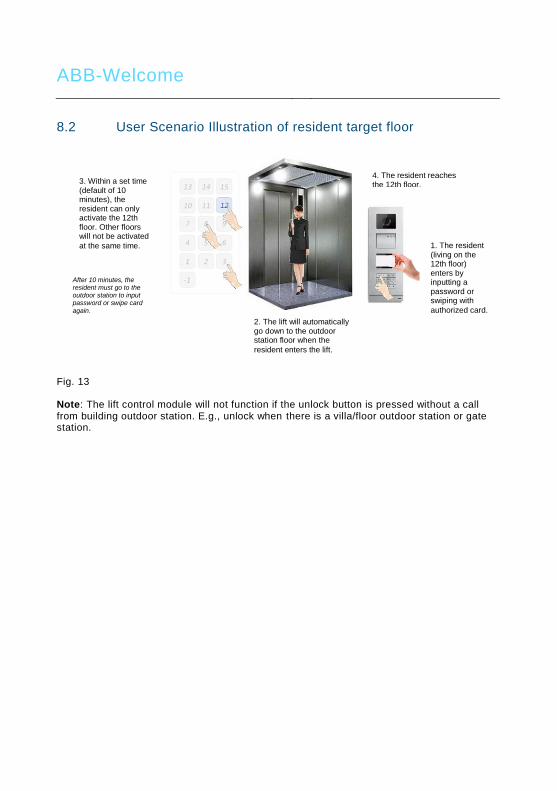
ABB-Welcome
Pos: 43 /Busch-Jaeg er (Neustr uktur)/Modul- Struktur /Online-Dokumentati on/Überschriften (--> Für alle D okumente <--)/1. Ebene/A - F /Bedienung @ 11\mod_1279185541649_15.docx @ 83043 @ 1 @ 1 Pos : 44 /Busch-Jaeg er (Neustr uktur)/Modul- Struktur /Online-Dokumentati on/Bedienung/Di mmer/Bedi enung - 6591 U-101 @ 23\mod_1333091293158_15.docx @ 207069 @ @ 1
8.2 User Scenario Illustration of resident target floor
Fig. 13 Note: The lift control module will not function if the unlock button is pressed without a call from building outdoor station. E.g., unlock when there is a villa/floor outdoor station or gate station.
1. The resident (living on the 12th floor) enters by inputting a password or swiping with
authorized card. 2. The lift will automatically go down to the outdoor station floor when the
resident enters the lift.
3. Within a set time (default of 10 minutes), the resident can only activate the 12th floor. Other floors will not be activated
at the same time.
After 10 minutes, the resident must go to the outdoor station to input password or swipe card again.
4. The resident reaches the 12th floor.

ABB-Welcome
9 Configuration through PC software
9.1 Connected to PC
During configuration, the lift control adaptor can be connected directly to the PC so that the installed software (ABB-Welcome PC Configuration Tool) can be used. Essentially, there is no need for local power supply during configuration. Upon completing configuration, click "Send the Configuration" to upload the configured file to the system. Refer to instructions below. Note: Only supports Microsoft Windows
Fig. 14
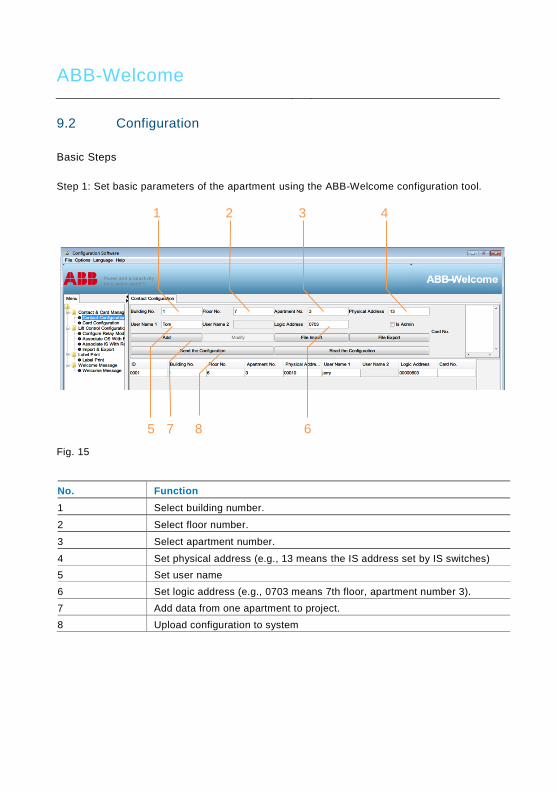
ABB-Welcome
9.2 Configuration
Basic Steps
Step 1: Set basic parameters of the apartment using the ABB-Welcome configuration tool.
Fig. 15
No. Function
1 Select building number.
2 Select floor number.
3 Select apartment number.
4 Set physical address (e.g., 13 means the IS address set by IS switches)
5 Set user name
6 Set logic address (e.g., 0703 means 7th floor, apartment number 3).
7 Add data from one apartment to project.
8 Upload configuration to system
1 2 3 4
5 6 7 8

ABB-Welcome
Step 2: Select building, M2307 and configure parameters of each relay
Fig. 16
No. Function
1 Select building number
2 Select M2307 number
3 Click “Add” to add a new M2307
4 Select ON or OFF for connecting the relay
5 Select NO or NC for output type
6 Set relay operation time (1-3,600 seconds)
7 Show all M2307 parameters Note: In order to ensure building is configured properly, please finish each step before starting installation in a new building.
1 2 3
4 5 6
7

ABB-Welcome
Step 3: Associate outdoor station with M2307
Fig. 17
No. Function
1 Building number (same as step2)
2 Select outdoor station number
3 Select Relay No. of M2307
4 Click “Add” to associate outdoor station with relay
5 Send all parameters to M2306
6 Input password*. Default password is 123456.
*Please write down this password. If password is forgotten, software must
be reloaded.
1 2 3
4 5
6

ABB-Welcome
Step 4: Associate indoor station with M2307
Fig. 18
No. Function
1 Building number (same as step2)
2 Select indoor station physical address
3 Select relay number of M2307
4 Select outdoor station number (floor number of outdoor station installed)
5 Click “Add” to associate indoor station with relay
6 Send all parameters to M2306
7 Input password. Default password is 123456.
1 2 3
5 6 7
4

ABB-Welcome
Optional steps: Step 5: Export all data from this project or import data for new project
Fig. 19
No. Function
1 Export all lift control configuration data to one read-only Excel file. (Export
the lift control configuration of each building for future reference.)
2 Import data for a new project from Excel file
1 2

ABB-Welcome
Step 6: Save as one new project
Fig. 20
No. Function
1 Save as one new project: *.xml
1

ABB-Welcome
Step 7: Import existing project data to new outdoor station, guard unit and lift control
Fig. 21
No. Function
1 Open one existing project: *.xml
1
ABB-Welcome
Notice === Ende der Liste für Textmar ke Backcover ===
We reserve the right to, at any time, make technical changes or changes in the content
of this document without prior notice.
The detailed specifications agreed to at the time of ordering applies to all orders. ABB
accepts no responsibility for possible errors or incompleteness in this document.
We reserve all rights to this document and the topics and illustrations contained therein.
The document and its contents, or excerpts thereof, must not be reproduced,
transmitted or reused by third parties without prior written consent by ABB.

VER:1.0 │ │ 20.10.2015
ABB-Welcome
Поз. 2 /Di nA4 - Anleitungen Online/Inhal t/KN X/D oorEntr y/83220- AP- xxx/Titelbl att - 83220-AP- xxx - ABB @ 19\mod_1323249806476_15.docx @ 111084 @ @ 1
Модуль управления
лифтом
M2306
M2307
=== Ende der Liste für Textmar ke Cover ===

ABB-Welcome
| — 2 —
Поз. 4 /Busch-Jaeger (N eus truktur)/M odul-Str uktur/Online-D okumentation/Inhal tsverzeichnis (--> Für alle D okumente <--)/Inhaltsverzeichnis @ 19\mod_1320649044386_15.docx @ 109653 @ @ 1
1 Безопасность ............................................................................................... 3 2 Окружающая среда...................................................................................... 3
2.1 Устройства ABB .......................................................................... 3 3 Технические данные .................................................................................... 4 4 Функция ........................................................................................................ 5 5 Соединение .................................................................................................. 6
5.1 M2306 ........................................................................................... 6 5.2 M2307 ........................................................................................... 7
6 Монтаж / установка .................................................................................... 10 6.1 Требования к квалификации электрика .................................. 10 6.2 Монтаж....................................................................................... 12
7 Пользовательский вариант ....................................................................... 13 7.1 Один M2306 и M2307 ................................................................ 13 7.2 Один M2306 и M2307 ................................................................ 15 7.3 До двух лифтов на здание ....................................................... 17 7.4 До четырех лифтов на здание ................................................. 18
8 Эксплуатация ............................................................................................. 19 8.1 Рисунок пользовательского сценария нужного для посетителя
этажа .......................................................................................... 19 8.2 Рисунок пользовательского сценария нужного для жильца
этажа .......................................................................................... 20 9 Конфигурация с помощью программного обеспечения ПК .................... 21
9.1 Подключение к ПК..................................................................... 21 9.2 Конфигурация ........................................................................... 22
=== Ende der Liste für Textmar ke TOC ===
ABB-Welcome
| — 3 —
Поз. 6 /Busch-Jaeger (N eus truktur)/M odul-Str uktur/Online-D okumentation/Überschrif ten (--> Für alle Dokumente <--)/1. Ebene/S - T/Sicherheit @ 18\mod_1302612791790_15.docx @ 103357 @ 1 @ 1
1 Безопасность Поз. 7 /Busch-Jaeger (N eus truktur)/M odul-Str uktur/Online-D okumentation/Sicherheit (--> Für alle D okumente <--)/War nhi nweise/Sicher heit - 230 V @ 18\mod_1302606816750_15.docx @ 103308 @ @ 1
Предупреждение!
Электрическое напряжение!
Опасность гибели или возникновения пожара в результате
воздействия электрического напряжения 100–240 В.
– Работу на системах с напряжением питания 100–240 В могут
проводить только авторизованные электрики!
– Перед установкой и/или сборкой отключите подачу напряжения
от электросети!
Поз. 10 /Busch-Jaeg er (Neustr uktur)/Modul-Struktur/Online-Dokumentati on/Überschriften (--> Für alle D okumente <--)/1. Ebene/U - Z/U mwelt @ 18\mod_1302614158967_15.docx @ 103383 @ 1 @ 1
2 Окружающая среда Поз. 11 /Busch-Jaeg er (Neustr uktur)/Modul-Struktur/Online-Dokumentati on/U mwel t (--> Für alle Dokumente <--)/inweise/Hi nweis - U mwelt - Hinweis Elektrog eräte @ 18\mod_1302763973434_15.docx @ 103500 @ @ 1
Сведения по защите окружающей среды
Используемые электрические и электронные устройства не должны
утилизироваться вместе с бытовыми отходами.
– Устройство содержит дорогие исходные материалы, которые
пригодны для вторичной переработки. Поэтому утилизировать
данное устройство необходимо в соответствующем сборном
пункте.
Поз. 12 /DinA4 - Anl eitungen Online/Ueberschrif ten/2./ABB Geraete @ 19\mod_1323162843832_15.docx @ 110875 @ 2 @ 1
2.1 Устройства ABB Поз. 13 /Busch-Jaeg er (Neustr uktur)/Modul-Struktur/Online-Dokumentati on/U mwel t (--> Für alle Dokumente <--)/Hi nweise/Hi nweis - U mwelt - ABB El ektr oger äte @ 19\mod_1323162745839_15.docx @ 110867 @ @ 1
Все упаковочные материалы и устройства ABB содержат маркировку и
контрольные уплотнения для правильной утилизации. Утилизацию упаковочного
материала, электрических устройств и их компонентов всегда следует проводить
на авторизованных сборных пунктах и в специализированных компаниях.
Изделия ABB соответствуют юридическим требованиям, в частности
законодательным актам, относящимся к электрическим и электронным
устройствам, а также постановлению REACH.
(Директива ЕС 2002/96/EG «Утилизация отходов производства электрического и
электронного оборудования» (WEEE) и «Директива ЕС по ограничению
использования опасных веществ» 2002/95/EG RoHS)
(Постановление ЕС REACH и закон по его вводу в действие (EG) № 1907/2006)
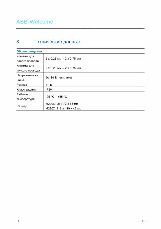
ABB-Welcome
| — 4 —
3 Технические данные Поз. 14 /Busch-Jaeg er (Neustr uktur)/Modul-Struktur/Online-Dokumentati on/Technische Daten/Di mmer/Technische Daten - 6591 U- 101 @ 23\mod_1333089085280_15.docx @ 207039 @ @ 1
Общие сведения
Клеммы для
одного провода 2 x 0,28 мм – 2 x 0,75 мм
Клеммы для
тонкого провода 2 x 0,28 мм – 2 x 0,75 мм
Напряжение на
шине 20–30 В пост. тока
Размер 4 TE
Класс защиты IP20
Рабочая
температура -25 °C – +55 °C
Размер M2306: 90 x 72 x 65 мм
M2307: 216 x 110 x 45 мм
ABB-Welcome
| — 5 —
Поз. 15 /Busch-Jaeg er (Neustr uktur)/Modul-Struktur/Online-Dokumentati on/Steuermodul e - Onli ne-D okumentation (--> Für all e D okumente <--)/++++++++++++ Seitenumbruch ++++++++++++ @ 9\mod_1268898668093_0.docx @ 52149 @ @ 1
4 Функция Поз. 22 /Busch-Jaeg er (Neustr uktur)/Modul-Struktur/Online-Dokumentati on/Überschriften (--> Für alle D okumente <--)/2. Ebene/G - L/Lastarten @ 20\mod_1326269704379_15.docx @ 136905 @ 2 @ 1
В модули управления лифтом входят переходное устройство М (M2306) и модуль реле управления лифтом (M2307). Эти два устройства вместе осуществляют управление лифтом только на разрешенных этажах. Если постоянный жилец нажимает кнопку «Разблокировка» при получении звонка от гостя с вызывной станции (ВС), или авторизованный пользователь проводит картой по считывающему устройству или вводит правильный пароль, лифт автоматически опустится вниз до того этажа, на котором установлена вызывная станция (ВС). Затем лифт поднимается на определенный этаж, где живет жилец. Лифт не может останавливаться на других этажах, даже если на нем нажата другая кнопка этажа. Конфигурация должна проводиться с помощью специализированного программного обеспечения при подключении переходного устройства М к ПК/ноутбуку.
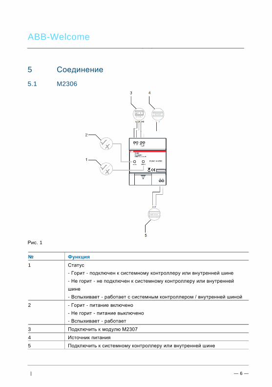
ABB-Welcome
| — 6 —
Поз. 30 /Busch-Jaeg er (Neustr uktur)/Modul-Struktur/Online-Dokumentati on/Überschriften (--> Für alle D okumente <--)/1. Ebene/A - F/Anschluss @ 19\mod_1309248278435_15.docx @ 107413 @ 1 @ 1
5 Соединение
5.1 M2306 Поз. 31 /Busch-Jaeg er (Neustr uktur)/Modul-Struktur/Online-Dokumentati on/Anschl uss/Di mmer/Anschluss - 6591 U-101 @ 23\mod_1333093920008_15.docx @ 207132 @ @ 1
Рис. 1
№ Функция
1 Статус
- Горит - подключен к системному контроллеру или внутренней шине
- Не горит - не подключен к системному контроллеру или внутренней
шине
- Вспыхивает - работает с системным контроллером / внутренней шиной
2 - Горит - питание включено
- Не горит - питание выключено
- Вспыхивает - работает
3 Подключить к модулю M2307
4 Источник питания
5 Подключить к системному контроллеру или внутренней шине

ABB-Welcome
| — 7 —
5.2 M2307
5.2.1 Поз. 31 /Busch-Jaeg er (Neustr uktur)/Modul-Struktur/Online-Dokumentati on/Anschl uss/Di mmer/Anschluss - 6591 U-101 @ 23\mod_1333093920008_15.docx @ 207132 @ @ 1
Рис. 2
№ Функция
1 Индикатор питания
- Горит - питание включено
- Не горит - питание выключено
2 Индикатор настройки
- Вспыхивает во время нормальной работы
3 Адрес
Установка адреса модуля
Диапазон адресов от 1 до 16, используются только 4 левые бита.
4 Источник питания
5 Подключить к модулю M2306
6 Подключить к контроллеру лифта

ABB-Welcome
| — 8 —
Поз. 24 /Busch-Jaeg er (Neustr uktur)/Modul-Struktur/Online-Dokumentati on/Steuermodul e - Onli ne-D okumentation (--> Für all e D okumente <--)/++++++++++++ Seitenumbruch ++++++++++++ @ 9\mod_1268898668093_0.docx @ 52149 @ @ 1
Различный режим работы в соответствии с настройками программного обеспечения ПК
Если подключено NC-COM
Питание выкл., все реле будут замкнуты
Питание вкл., все реле будут разомкнуты
При наличии команды от модуля управления лифтом будет замыкаться соответствующее
реле
Если подключено NO-COM
Питание выкл., все реле будут разомкнуты
Питание вкл., все реле будут разомкнуты
При наличии команды от модуля управления лифтом будет замыкаться соответствующее
реле
ИНДИКАТОР
НЕ ГОРИТ
ИНДИКАТОР
ГОРИТ
ИНДИКАТОР НЕ ГОРИТ
ИНДИКАТОР НЕ ГОРИТ
ИНДИКАТОР НЕ ГОРИТ
ИНДИКАТ
ОР ГОРИТ
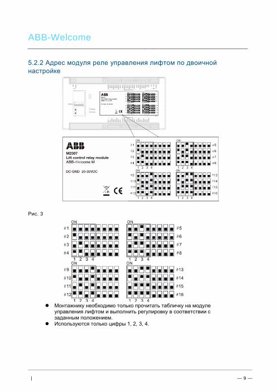
ABB-Welcome
| — 9 —
5.2.2 Адрес модуля реле управления лифтом по двоичной
настройке
Рис. 3
Монтажнику необходимо только прочитать табличку на модуле управления лифтом и выполнить регулировку в соответствии с заданным положением.
Используются только цифры 1, 2, 3, 4.
ABB-Welcome
| — 10 —
6 Монтаж / установка Поз. 34 /Busch-Jaeg er (Neustr uktur)/Modul-Struktur/Online-Dokumentati on/Sicherheit (--> Für all e Dokumente <--)/Warnhinweise/Si cherheit - Ni ederspannungs- und 230 V-Leitung en @ 18\mod_1302617821491_15.docx @ 103465 @ @ 1
Предупреждение!
Электрическое напряжение!
Опасность гибели или возникновения пожара в результате
воздействия электрического напряжения 230 В.
– Низковольтные кабели и кабели напряжения 230 В не должны
подключаться в одной и той же розетке, устанавливаемой в
стене заподлицо!
При коротком замыкании напряжение 230 В может попасть в
низковольтную линию.
Поз. 35 /Busch-Jaeg er (Neustr uktur)/Modul-Struktur/Online-Dokumentati on/Sicherheit (--> Für all e Dokumente <--)/Warnhinweise/Si cherheit - Vorgeschaltete Sicher ung abschalten @ 20\mod_1326441711467_15.docx @ 137043 @ @ 1
Предупреждение!
Электрическое напряжение!
Во время проведения работ с системой освещения необходимо
отключить предохранитель выше по линии.
Поз. 36 /Busch-Jaeg er (Neustr uktur)/Modul-Struktur/Online-Dokumentati on/Sicherheit (--> Für all e Dokumente <--)/Warnhinweise/Si cherheit - Fachkenntnisse @ 18\mod_1302774384017_15.docx @ 103564 @ 2 @ 1
6.1 Требования к квалификации электрика
Предупреждение!
Электрическое напряжение!
Для установки устройства электрик должен обладать необходимыми
знаниями и опытом в области электротехники.
• Неправильная установка подвергает опасности вашу жизнь и
жизнь пользователя электрической системы.
• Неправильная установка может вызвать серьезное повреждение
имущества, например, в результате пожара.
Минимальные знания и требования по установке:
• Применяйте «пять правил безопасности» (DIN VDE 0105, EN
50110):
1. Отключайте устройство от электросети.
ABB-Welcome
| — 11 —
2. Примите меры от случайного включения.
3. Убедитесь в отсутствии напряжения.
4. Подключите заземление.
5. Накрывайте соседние детали, находящие под
напряжением, или устанавливайте для них ограждение.
• Пользуйтесь подходящей защитной одеждой.
• Используйте только подходящие инструменты и измерительные
устройства.
• Проверяйте тип электросети (TN-, IT-, TT-система), чтобы
обеспечить безопасность подачи питания (классическое
подключение к заземлению, защитное заземление, необходимые
дополнительные измерения и т.д.).

ABB-Welcome
| — 12 —
6.2 Монтаж Поз. 38 /Busch-Jaeg er (Neustr uktur)/Modul-Struktur/Online-Dokumentati on/Montage/all e Geräte/Montage - UP-D osen - D IN 49073- 1 oder geeignetes Aufputzg ehaeuse - Ohne D ocvariable @ 20\mod_1325766034453_15.docx @ 136593 @ @ 1
Устройство необходимо устанавливать только на монтажные рейки в соответствии
с DIN EN 50022.
Модуль M2306 настоятельно рекомендуется для установки в помещении с
двигателями лифта на верхнем этаже или электрического вертикально
проложенного кабеля; в то время как модуль M2307 настоятельно рекомендуется
устанавливать в кабине лифта.
Рис. 4
Рис. 5: Демонтаж

ABB-Welcome
| — 13 —
7 Пользовательский вариант
7.1 Один M2306 и M2307
Высотное здание не более 16 этажей с одним лифтом
Поз. 41 /Busch-Jaeg er (Neustr uktur)/Modul-Struktur/Online-Dokumentati on/Inbetri ebnahme/Di mmer /Inbetriebnahme - 6591 U-101 @ 19\mod_1311948781023_15.docx @ 108300 @ 222 @ 1
Рис. 6: Топология
Переходное устройство

ABB-Welcome
| — 14 —
Проводка с помощью одного модуля M2306 и M2307
Рис. 7

ABB-Welcome
| — 15 —
7.2 Один M2306 и M2307
Высотное здание более 16 этажей с одним лифтом
Рис. 8: Топология
Переходное устройство
Системный мини-
контроллер (M2301)
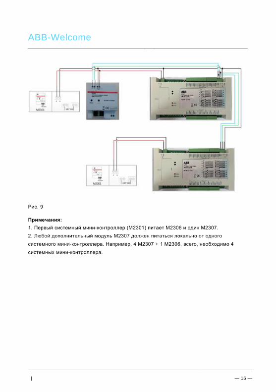
ABB-Welcome
| — 16 —
Рис. 9
Примечания:
1. Первый системный мини-контроллер (M2301) питает M2306 и один M2307.
2. Любой дополнительный модуль M2307 должен питаться локально от одного
системного мини-контроллера. Например, 4 M2307 + 1 M2306, всего, необходимо 4
системных мини-контроллера.

ABB-Welcome
| — 17 —
7.3 До двух лифтов на здание
Высотное здание более 16 этажей
Рис. 10: Топология
Примечание: Код адреса не может повторяться.
Переходное устройство

ABB-Welcome
| — 18 —
7.4 До четырех лифтов на здание
Высотное здание более 16 этажей
Рис. 11: Топология
Поз. 42 /Busch-Jaeger (Neustruktur)/Modul-Struktur/Online-Dokumentation/Steuermodule - Online-Dokumentation (--> Für alle Dokumente <--)/++++++++++++ Seitenumbruch ++++++++++++ @ 9\mod_1268898668093_0.docx @ 52149 @ @ 1 Примечание: Код адреса не может повторяться.
Переходное устройство
Переходное устройство

ABB-Welcome
| — 19 —
Поз. 43 /Busch-Jaeg er (Neustr uktur)/Modul-Struktur/Online-Dokumentati on/Überschriften (--> Für alle D okumente <--)/1. Ebene/A - F/Bedienung @ 11\mod_1279185541649_15.docx @ 83043 @ 1 @ 1
8 Эксплуатация Поз. 44 /Busch-Jaeg er (Neustr uktur)/Modul-Struktur/Online-Dokumentati on/Bedienung/Di mmer /Bedi enung - 6591 U-101 @ 23\mod_1333091293158_15.docx @ 207069 @ @ 1
8.1 Рисунок пользовательского сценария нужного для
посетителя этажа
Рис. 12
Поз. 42 /Busch-Jaeg er (Neustr uktur)/Modul-Struktur/Online-Dokumentati on/Steuermodul e - Onli ne-D okumentation (--> Für all e D okumente <--)/++++++++++++ Seitenumbruch ++++++++++++ @ 9\mod_1268898668093_0.docx @ 52149 @ @ 1
1. Посетитель вводит код вызова 12-ого
этажа
2. Жилец нажимает кнопку «Разблокировка» любого абонентского терминала (АТ) Welcome M.
3. Лифт опускается автоматически до этажа с установленной вызывной станцией (ВС), посетитель
входит в лифт.
4. В пределах заданного времени (по умолчанию 10 минут) посетитель может только включить кнопку этажа № 12, другие номера этажей включены
не будут все это время.
5. Посетитель добирается до 12 этажа.
Если пройдет больше 10 минут, посетителю необходимо снова подойти к вызывной станции и вызвать нужного жильца.
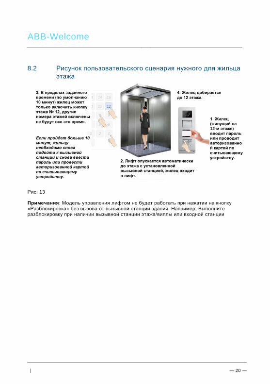
ABB-Welcome
| — 20 —
Поз. 43 /Busch-Jaeg er (Neustr uktur)/Modul-Struktur/Online-Dokumentati on/Überschriften (--> Für alle D okumente <--)/1. Ebene/A - F/Bedienung @ 11\mod_1279185541649_15.docx @ 83043 @ 1 @ 1 Поз. 44 /Busch-Jaeg er (Neustr uktur)/Modul-Struktur/Online-Dokumentati on/Bedienung/Di mmer /Bedi enung - 6591 U-101 @ 23\mod_1333091293158_15.docx @ 207069 @ @ 1
8.2 Рисунок пользовательского сценария нужного для жильца
этажа
Рис. 13 Примечания: Модель управления лифтом не будет работать при нажатии на кнопку «Разблокировка» без вызова от вызывной станции здания. Например, Выполните разблокировку при наличии вызывной станции этажа/виллы или входной станции
1. Жилец (живущий на 12-м этаже) вводит пароль или проводит авторизованной картой по считывающему
устройству. 2. Лифт опускается автоматически до этажа с установленной вызывной станцией, жилец входит
в лифт.
3. В пределах заданного времени (по умолчанию 10 минут) жилец может только включить кнопку этажа № 12, другие номера этажей включены
не будут все это время.
4. Жилец добирается
до 12 этажа.
Если пройдет больше 10 минут, жильцу необходимо снова подойти к вызывной станции и снова ввести пароль или провести авторизованной картой по считывающему устройству.

ABB-Welcome
| — 21 —
9 Конфигурация с помощью программного
обеспечения ПК
9.1 Подключение к ПК Во время конфигурации переходное устройство управления лифтом можно непосредственно подключить к ПК, на котором может использоваться установленное программное обеспечение (программа конфигурации ABB Welcome M на ПК). Другими словами, во время конфигурации локального источника питания не требуется. По завершению конфигурации нажмите кнопку Send the Configuration (Отправить конфигурацию), чтобы загрузить сконфигурированный файл в систему. См. общее пошаговое введение на слайдах ниже. Примечания: Поддерживается только ПК с Windows
Рис. 14

ABB-Welcome
| — 22 —
9.2 Конфигурация
Основные шаги Шаг 1. Установка основных параметров подъезда с помощью программы конфигурации Welcome M
Рис. 15
№ Функция
1 Выбрать номер здания.
2 Выбрать номер этажа.
3 Выбрать номер подъезда.
4 Установить физический адрес (например 13 означает адрес АТ,
установленный с помощью переключателей АТ)
5 Задать имя пользователя
6 Установить логический адрес (например 0703 означает: номер этажа
07, номер подъезда 03)
7 Добавить данные для одного подъезда в проект
8 Загрузить конфигурацию в систему
2 3
5 6 7 8
4 1

ABB-Welcome
| — 23 —
Шаг 2. Выбрать здание, модуль М2307 и настроить параметры каждого реле
Рис. 16
№ Функция
1 Выбор номера здания.
2 Выбор номера модуля М2307.
3 Нажать кнопку Add (Добавить), чтобы добавить новый модуль М2307
4 Выбрать ON (ВКЛ.) или OFF (ВЫКЛ.) для подключения реле
5 Выбрать тип выхода: NO (нормально-разомкнутый) или NC
(нормально- замкнутый)
6 Установить время работы реле (от 1 до 3600 с)
7 Показать все параметры модуля M2307
Примечание: Чтобы убедиться в правильности настройки одного здания, для каждого здания выполните шаги в таком порядке: 2, 3, 4, 5. Затем повторите этот цикл для нового здания.
1 2 3
4 5 6
7

ABB-Welcome
| — 24 —
Шаг 3. Связать ВС с модулем M2307
Рис. 17
№ Функция
1 Номер здания (как в шаге 2)
2 Выбрать номер ВС
3 Выбрать номер реле модуля М2307
4 Нажать кнопку Add (Добавить), чтобы связать ВС с реле
5 Передать все параметры в модуль М2306
6 Ввести пароль* (по умолчанию: 123456)
* запишите этот пароль, чтобы не забыть, перегрузите это
программное обеспечение!
1 2 3
4 5
6

ABB-Welcome
| — 25 —
Шаг 4. Связать АТ с модулем M2307
Рис. 18
№ Функция
1 Номер здания (как в шаге 2)
2 Выбрать физический адрес АТ
3 Выбрать номер реле модуля М2307
4 Выбрать номер ВС (номер этажа установленной ВС)
5 Нажать кнопку Add (Добавить), чтобы связать АТ с реле
6 Передать все параметры в модуль М2306
7 Ввести пароль (по умолчанию: 123456)
1 2 3
5
6
7
4
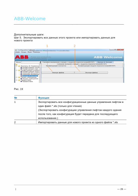
ABB-Welcome
| — 26 —
Дополнительные шаги: Шаг 5. Экспортировать все данные этого проекта или импортировать данные для нового проекта
Рис. 19
№ Функция
1 Экспортировать все конфигурационные данные управления лифтом в
один файл *.xls (только для чтения)
(Экспортировать конфигурацию управления лифтом каждого здания
после того, как конфигурация будет передана для последующего
использования.)
2 Импортировать данные для нового проекта из одного файла *.xls
1 2
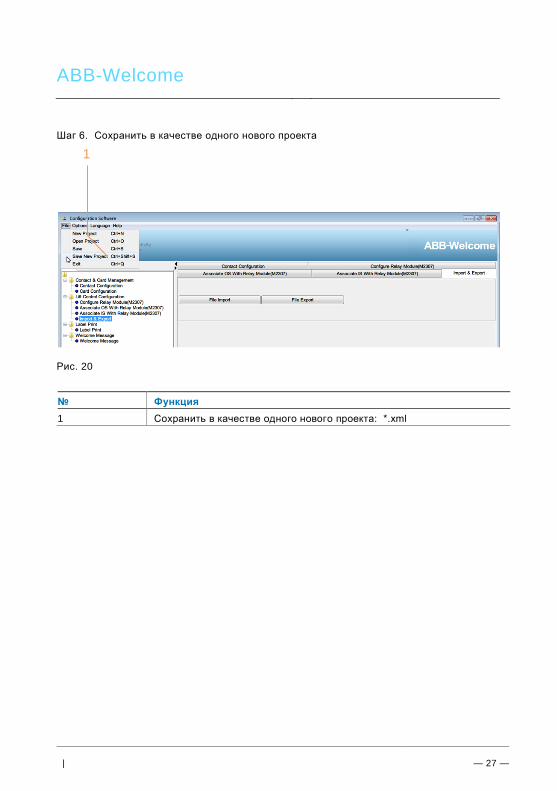
ABB-Welcome
| — 27 —
Шаг 6. Сохранить в качестве одного нового проекта
Рис. 20
№ Функция
1 Сохранить в качестве одного нового проекта: *.xml
1

ABB-Welcome
| — 28 —
Шаг 7. Открыть данные одного существующего проекта в новой ВС, станции безопасности и модуле управления лифтом
Рис. 21
№ Функция
1 Открыть один существующий проект: *.xml
1