Embed Size (px)
Citation preview
eni Angola WOP EAST HUB Field D&C performance overview end of 1st Phase
Luanda, August 02nd, 2016
Agenda
East Hub Project Overview
HSE
Time & NPT Analysis
Lessons Learnt
2
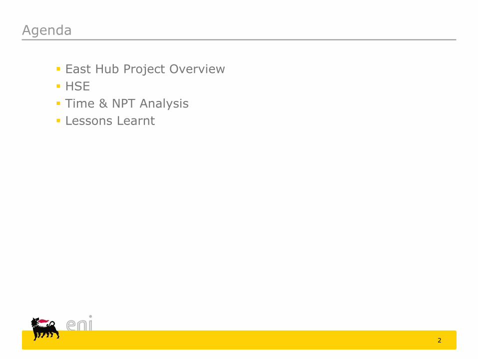
Map
3
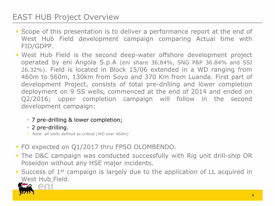
Scope of this presentation is to deliver a performance report at the end of West Hub Field development campaign comparing Actual time with FID/GDPP.
West Hub Field is the second deep-water offshore development project operated by eni Angola S.p.A (eni share 36,84%, SNG P&P 36.84% and SSI
26.32%). Field is located in Block 15/06 extended in a WD ranging from 460m to 560m, 130km from Soyo and 370 Km from Luanda. First part of development Project, consists of total pre-drilling and lower completion deployment on 9 SS wells, commenced at the end of 2014 and ended on Q2/2016; upper completion campaign will follow in the second development campaign:
7 pre-drilling & lower completion;
2 pre-drilling. Note: all wells defined as critical (WD over 460m)
FO expected on Q1/2017 thru FPSO OLOMBENDO.
The D&C campaign was conducted successfully with Rig unit drill-ship OR Poseidon without any HSE major incidents.
Success of 1st campaign is largely due to the application of LL acquired in West Hub Field.
4
EAST HUB Project Overview
5
HSE
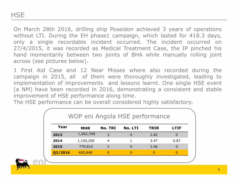
On March 28th 2016, drilling ship Poseidon achieved 3 years of operations without LTI. During the EH phase1 campaign, which lasted for 418.3 days, only a single recordable incident occurred. The incident occurred on 27/4/2015, it was recorded as Medical Treatment Case, the IP pinched his hand momentarily between two joints of BHA while manually rolling joint across (see pictures below).
1 First Aid Case and 12 Near Misses where also recorded during the campaign in 2015, all of them were thoroughly investigated, leading to implementation of improvements and lessons learnt. One single HSE event (a NM) have been recorded in 2016, demonstrating a consistent and stable improvement of HSE performance along time. The HSE performance can be overall considered highly satisfactory.
Year MHR No. TRI No. LTI TRIR LTIF
2013 1,062,348 3 0 2.82 0
2014 1,150,200 4 1 3.47 0.87
2015 779,810 2 0 2.56 0
Q2/2016 400,848 0 0 0 0
WOP eni Angola HSE performance
6
EH D&C Performance overview
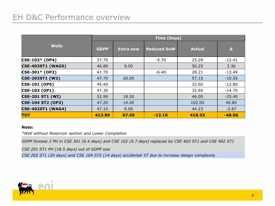
Wells
Time (Days)
GDPP Extra sow Reduced SoW Actual Δ
CSE-102* (OP4) 37.70 -5.70 25.29 -12.41
CSE-403ST1 (WAG5) 46.89 9.00 50.25 3.36
CSE-301* (OP2) 41.70 -6.40 28.21 -13.49
CSE-202ST1 (W2) 47.70 20.00 57.15 -10.55
CSE-101 (OP5) 45.40 32.60 -12.80
CSE-103 (OP1) 47.30 32.60 -14.70
CSE-201 ST1 (WI) 52.90 18.50 46.00 -25.40
CSE-104 ST2 (OP3) 47.20 14.00 102.00 40.80
CSE-402ST1 (WAG4) 47.10 6.00 44.23 -2.87
TOT 413.89 67.50 -12.10 418.33 -48.06
Note:
*Well without Reservoir section and Lower Completion
GDPP foresee 2 PH in CSE 301 (6.4 days) and CSE 102 (5.7 days) replaced by CSE 403 ST1 and CSE 402 ST1
CSE 201 ST1 PH (18.5 days) out of GDPP sow
CSE 202 ST1 (20 days) and CSE 104 ST2 (14 days) accidental ST due to increase design complexity
7
EH D&C Performance overview
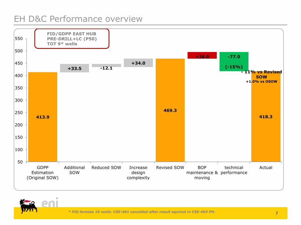
* FID foresee 10 wells. CSE-401 cancelled after result aquired in CSE-403 PH.
413.9
469.3
418.3
+33.5 -12.1 +34.0
+26.0 -77.0
(-15%)
- 11% vs Revised
SOW +1.0% vs OSOW
50
100
150
200
250
300
350
400
450
500
550
GDPP
Estimation
(Original SOW)
Additional
SOW
Reduced SOW Increase
design
complexity
Revised SOW BOP
maintenance &
moving
technical
performance
Actual
FID/GDPP EAST HUB PRE-DRILL+LC (P50) TOT 9* wells
8
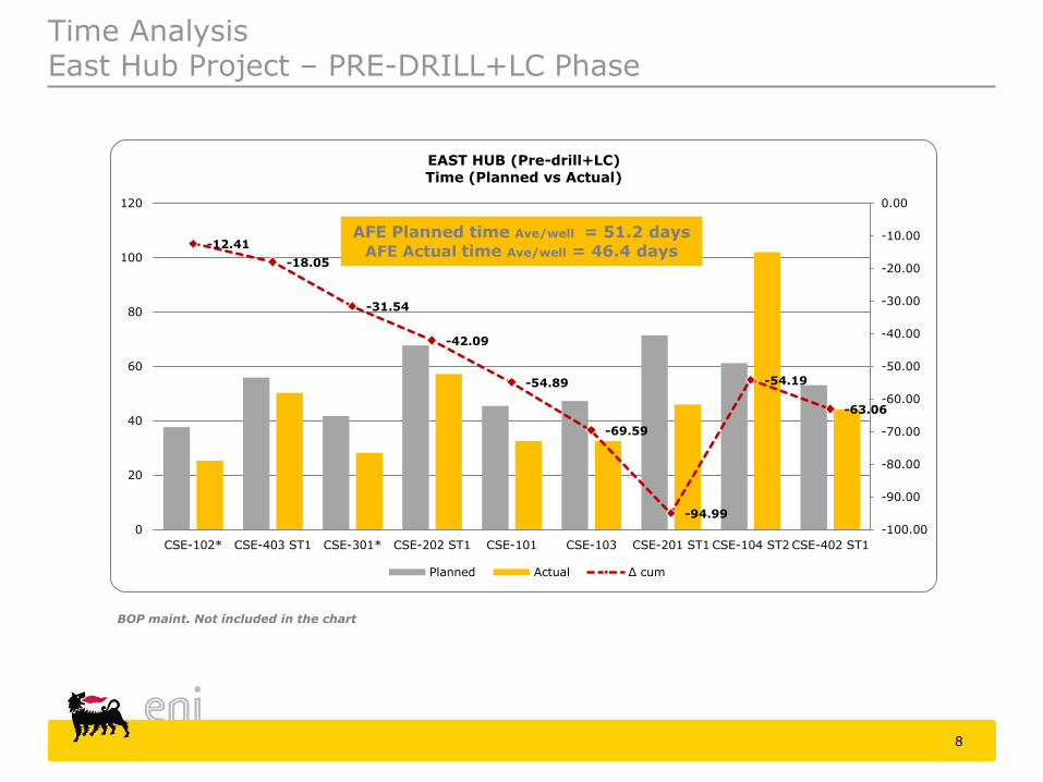
Time Analysis East Hub Project – PRE-DRILL+LC Phase
-12.41
-18.05
-31.54
-42.09
-54.89
-69.59
-94.99
-54.19
-63.06
-100.00
-90.00
-80.00
-70.00
-60.00
-50.00
-40.00
-30.00
-20.00
-10.00
0.00
0
20
40
60
80
100
120
CSE-102* CSE-403 ST1 CSE-301* CSE-202 ST1 CSE-101 CSE-103 CSE-201 ST1 CSE-104 ST2 CSE-402 ST1
EAST HUB (Pre-drill+LC)
Time (Planned vs Actual)
Planned Actual Δ cum
AFE Planned time Ave/well = 51.2 days AFE Actual time Ave/well = 46.4 days
BOP maint. Not included in the chart
9
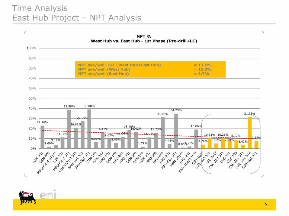
Time Analysis East Hub Project – NPT Analysis
22.76%
1.69% 3.19%
11.06%
38.58%
20.61%
27.09%
38.88%
6.22%
16.17%
9.67%
5.49%
11.62%
18.40% 16.42%
1.71%
11.03%
15.73%
31.06%
4.48%
34.73%
0.85% 1.90%
18.86%
3.79%
10.33%
5.02%
10.36%
7.60%
8.12%
3.43%
31.33%
7.37%
0%
10%
20%
30%
40%
50%
60%
70%
80%
90%
100%
NPT %
West Hub vs. East Hub - 1st Phase (Pre-drill+LC)
NPT ave/well TOT (West Hub+East Hub) = 13.5% NPT ave/well (West Hub) = 15.3% NPT ave/well (East Hub) = 9.7%
10
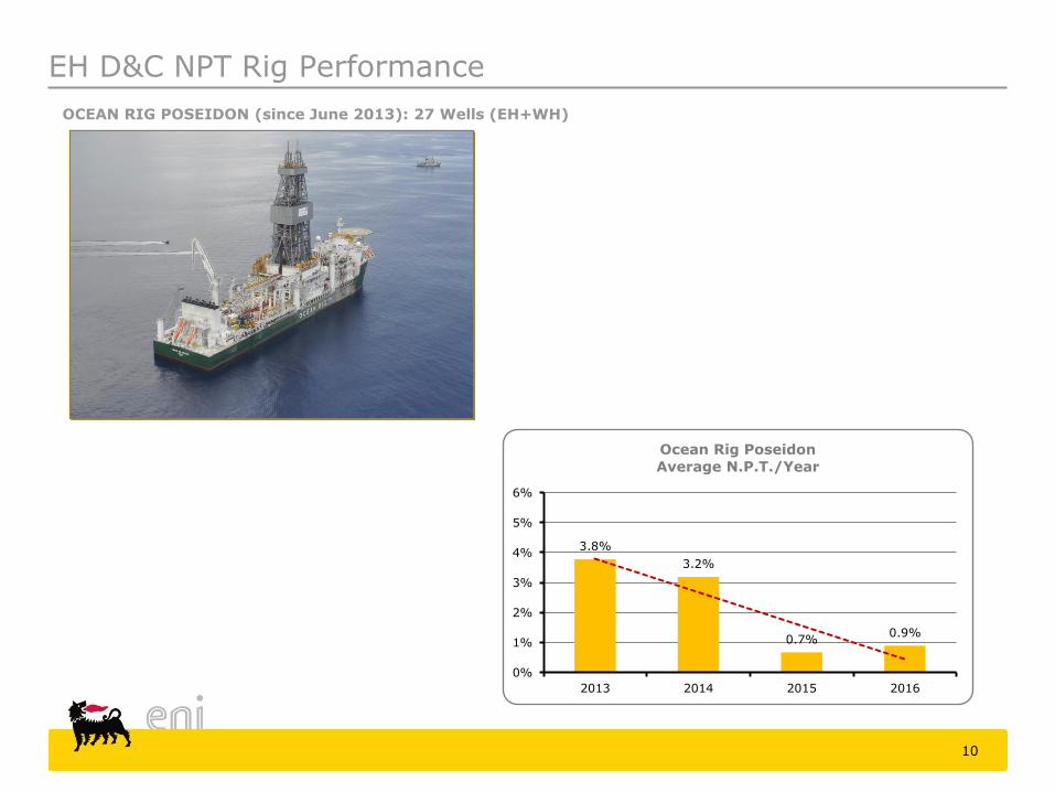
OCEAN RIG POSEIDON (since June 2013): 27 Wells (EH+WH)
EH D&C NPT Rig Performance
3.8%
3.2%
0.7% 0.9%
0%
1%
2%
3%
4%
5%
6%
2013 2014 2015 2016
Ocean Rig Poseidon
Average N.P.T./Year
EH Lessons Learnt 1/3
Main LL and new idea/technologies applied in East Hub Field.
Drilling:
Application of Automatic drilling tools (type Geopilot™) to drill ER wells
eni Lean Profile™ with NF™ tubulars
Ceramic centralizers (type Protech™)
RBP “Retrievable Bridge Plug” in TP&A instead of conventional cmt plug
Expandable Liner Hanger (Type Versaflex™) 11 ¾” and 9 7/8”
Non-Aqueous Drilling Fluid (LTOBM) to enhance bore hole stability
Reservoir Fluid OB-DIF (type Faze-pro™) to limit fm damage
Completion:
Prod wells completed in OHGP with Shunt Tubes™ technology
Inj. Wells completed with SAS “Stand Alone Screens” technology
FIV “Formation Isolation Valve” (Fortress™ type) used in both prod/inj. Wells to replace common flapper valve LBFV
11
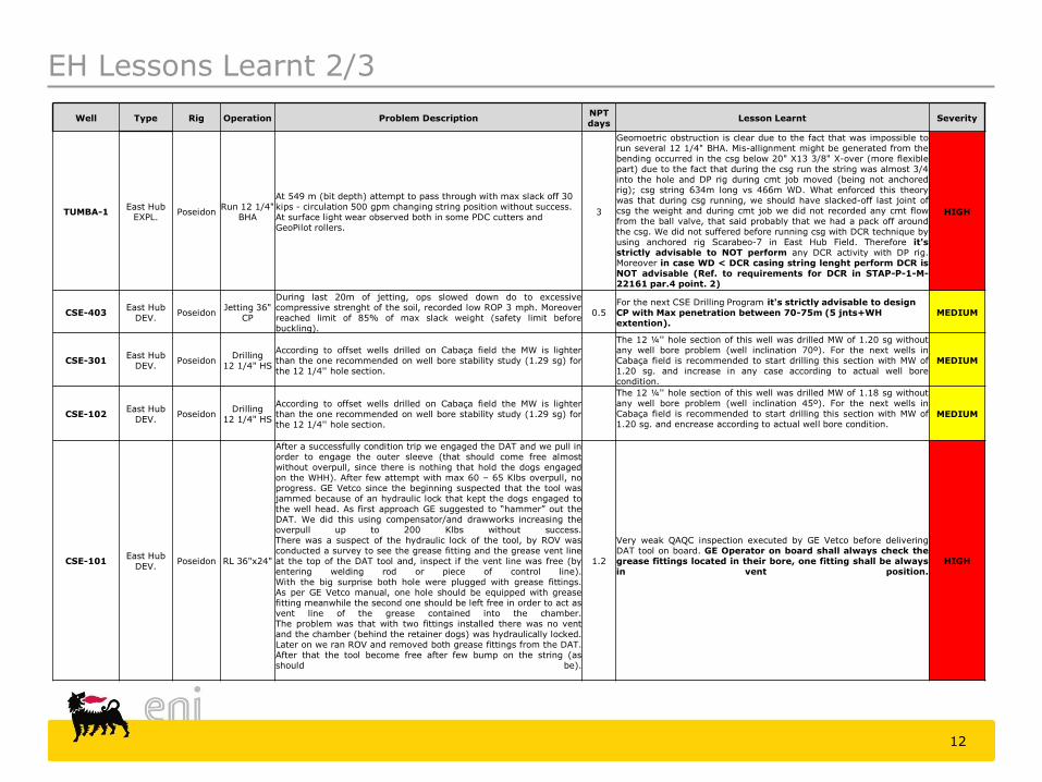
EH Lessons Learnt 2/3
12
Well Type Rig Operation Problem Description NPT days
Lesson Learnt Severity
TUMBA-1 East Hub
EXPL. Poseidon
Run 12 1/4" BHA
At 549 m (bit depth) attempt to pass through with max slack off 30 kips - circulation 500 gpm changing string position without success. At surface light wear observed both in some PDC cutters and GeoPilot rollers.
3
Geomoetric obstruction is clear due to the fact that was impossible to run several 12 1/4" BHA. Mis-allignment might be generated from the bending occurred in the csg below 20" X13 3/8" X-over (more flexible part) due to the fact that during the csg run the string was almost 3/4 into the hole and DP rig during cmt job moved (being not anchored rig); csg string 634m long vs 466m WD. What enforced this theory was that during csg running, we should have slacked-off last joint of csg the weight and during cmt job we did not recorded any cmt flow from the ball valve, that said probably that we had a pack off around the csg. We did not suffered before running csg with DCR technique by using anchored rig Scarabeo-7 in East Hub Field. Therefore it's strictly advisable to NOT perform any DCR activity with DP rig. Moreover in case WD < DCR casing string lenght perform DCR is NOT advisable (Ref. to requirements for DCR in STAP-P-1-M-22161 par.4 point. 2)
HIGH
CSE-403 East Hub
DEV. Poseidon
Jetting 36" CP
During last 20m of jetting, ops slowed down do to excessive compressive strenght of the soil, recorded low ROP 3 mph. Moreover reached limit of 85% of max slack weight (safety limit before buckling).
0.5 For the next CSE Drilling Program it's strictly advisable to design CP with Max penetration between 70-75m (5 jnts+WH extention).
MEDIUM
CSE-301 East Hub
DEV. Poseidon
Drilling 12 1/4" HS
According to offset wells drilled on Cabaça field the MW is lighter than the one recommended on well bore stability study (1.29 sg) for the 12 1/4'' hole section.
The 12 ¼'' hole section of this well was drilled MW of 1.20 sg without any well bore problem (well inclination 70º). For the next wells in Cabaça field is recommended to start drilling this section with MW of 1.20 sg. and increase in any case according to actual well bore condition.
MEDIUM
CSE-102 East Hub
DEV. Poseidon
Drilling 12 1/4" HS
According to offset wells drilled on Cabaça field the MW is lighter than the one recommended on well bore stability study (1.29 sg) for the 12 1/4'' hole section.
The 12 ¼'' hole section of this well was drilled MW of 1.18 sg without any well bore problem (well inclination 45º). For the next wells in Cabaça field is recommended to start drilling this section with MW of 1.20 sg. and encrease according to actual well bore condition.
MEDIUM
CSE-101 East Hub
DEV. Poseidon RL 36"x24"
After a successfully condition trip we engaged the DAT and we pull in order to engage the outer sleeve (that should come free almost without overpull, since there is nothing that hold the dogs engaged on the WHH). After few attempt with max 60 – 65 Klbs overpull, no progress. GE Vetco since the beginning suspected that the tool was jammed because of an hydraulic lock that kept the dogs engaged to the well head. As first approach GE suggested to “hammer” out the DAT. We did this using compensator/and drawworks increasing the overpull up to 200 Klbs without success. There was a suspect of the hydraulic lock of the tool, by ROV was conducted a survey to see the grease fitting and the grease vent line at the top of the DAT tool and, inspect if the vent line was free (by entering welding rod or piece of control line). With the big surprise both hole were plugged with grease fittings. As per GE Vetco manual, one hole should be equipped with grease fitting meanwhile the second one should be left free in order to act as vent line of the grease contained into the chamber. The problem was that with two fittings installed there was no vent and the chamber (behind the retainer dogs) was hydraulically locked. Later on we ran ROV and removed both grease fittings from the DAT. After that the tool become free after few bump on the string (as should be).
1.2
Very weak QAQC inspection executed by GE Vetco before delivering DAT tool on board. GE Operator on board shall always check the grease fittings located in their bore, one fitting shall be always in vent position.
HIGH
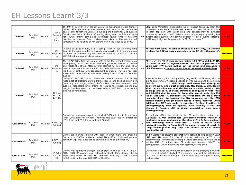
EH Lessons Learnt 3/3
13
CSE-202 East Hub
DEV. Poseidon
Run & Cement 11 ¾ Liner
11 3/4" X 13 3/8" liner hanger VersaFlex (Expandable Liner Hanger) failure. After performing liner cement job with succes, attempted several time to retrieve VersaFlex Running and Setting tool, no success. Decision was taken to back off landing string near the fish and try to fish. POOH landing string and attempted several time to fish with overshot, no success. Finaly decision was taken to abbandon the well temporarily and re-entry or not depending on the study to be done.
2.65
Stop using VersaFlex (Expandable Liner Hanger) tecnology from this contractor on eni wells. Route cause deployed 2 main failure: 1. failure to latch top dart with wiper plug and conseguently to activater conftigency plan with ball.2. failure to activate emergency setting tool disconnection system. It's strictly suggest to avoid susing Versaflex untill plug design will be proved to be "fit for purpouse".
HIGH
CSE-103 East Hub
DEV. Poseidon
Well Suspensio
n
In case of usage of RBP, it is a best practice to use kill string hang down to the plug in order to circulate any possible hyd migration from reservoir. In CSE-103 plug has been installed just below 10 3/4" x 9 5/8" XO without any kill string in place.
For the next wells, in case of absence of kill string, it's adviced to place the RBP as close as possible to the GP pkr (50m above).
MEDIUM
CSE-403 East Hub
DEV. Poseidon
Well Suspensio
n
The 12 ¼'' Slick BHA was run in hole to tag the second cement plug. While pulling out at 3041 m MD the BHA got stuck, unable to circulate and rotate the string. After several attempt to free the stuck BHA, decision was made to cut the drill pipe body and leave the Slick BHA in the hole to continue with abandonment operation. The pipe has been succesfully cut at 2868 m MD. (MW drilling 1.16-1.18 sg - ECD 1.19-1.20 sg)
1.93
After reach the TD of each section mainly 12 1/4'' and 8 1/2'' HS, circulate the well at highest no-loss rate and compensate ECD value with MW before pulling out the string and displacing a pills if necessary (unless severe losses occurred while driling) HIGH
CSE-104 East Hub
DEV. Poseidon
Drilling ER 12 1/4" HS
During 12 1/4" HS, about 1600m with max inclination of 67.0 deg, faced a lot of problems during drilling (losses) and tripping-out/in BHA (swabbing and surging effect). Before Pooh MW was increased from 1.19 sg (hole stable while drilling) to 1.21 sg to compensate the ECD margin N.6 days spent to cure losses (about 6000 bbls), by activating also PBL several times.
5
Major LL to be acquired during drilling long section in ER wells, with the aim to compromise Wellbore behavior prior to run csg and avoiding any BHA LIH: 1. Well Design: well access fault description doc from EXPL. and select accordingly MW trend. 2. BHA design shall be as slimmest and flexible as possible, reduce LWD package and so n. of stabs. Minimum configuration with PWD and GR-RES shall be used. 3. Preferable use bit with high JSA "Junk Slot Area" 4. minimize PBL offset from the bit 5. Deep evaluate chance to increase the MW to compensate the ECD margin before pooh (if severe losses already occurred while drilling, it's NOT advisable to execute). 6. Best Practices in drilling/tripping shall be applied, back reaming is the last chance. 7. Prepare LCM or similar material on time before starting drilling
HIGH
CSE-104ST1 East Hub
DEV. Poseidon
9 5/8" csg running
During csg running observed csg stuck @ 3030m in front of clear sand layer. Circulation not stopped, believed csg stuck due to differential. MW 1.21sg and PG 1.09 sg, well incl. 68.0 deg.
10
To mitigate differential stuck in the ER wells, these actions are suggested: 1. Use centralizers (preferable ceramic type) in a moderate number and place at the shoe (1C1) 2. Deep evaluate MW increasing before Pooh BHA 3. Load on board some lubricant (similar to "pipe-lax") to pump in case of stuck 4. Deep follow-up from Eng. Dept. and interact with SPT before running the job
HIGH
CSE-104ST2 East Hub
DEV. Poseidon
9 5/8" csg running
During csg running suffered with pack off phenomena and dragging. Csg stop at 3357m whilst expected TD 4195m. Pooh and perform condition trip. Well classified as ER with max 75 deg inclination.
10
In ER wells it is always preferable to split long csg section with LNR and TB, even if in the SS activity performing a TB is not recommended. Advantages of using a LNR is possibility to rotate and to set the LNR off bottom. Next ER wells shall foresee LNR+TB csg configuration. LNR to be provide with reaming/drilling shoe.
HIGH
CSE-202 ST1 East Hub
DEV. Poseidon
10 5/8 x 12 1/4"
HS
During Well operation changed the enlarger in the 10 5/8" x 12 1/4" BHA. HALL XR reamer was replaced by Smith Rhino Reamer due to impossibility to sustain a min FR 1050 GPM necessary to clean the hole for ER wells vs the max 900 GPM for the XR..
0
During well design the hydraulics simulation of the enlarging BHA shall be very well detailed studied. The enlarger item shall be selected on the bases of min FR to manage. That 'd avoid jeopardizing LOG during well activity.
MEDIUM

![SRU WiWHLV - AMENO Consorb Portateis.pdf · lqrydomrhpfolpdwl]domr $/8*8(5h9(1'$ hpdlo frphufldo#dphqr sw wop zzz dphqr sw hpdlo frphufldo qruwh#dphqr sw wop 48(17( )5,2 ,1'225 287'225](https://img.pdfslide.tips/doc/110x75/5f193f6f08db10095d5fb9a4/sru-wiwhlv-ameno-consorb-lqrydomrhpfolpdwldomr-885h91-hpdlo-frphufldodphqr.jpg)