Embed Size (px)
Citation preview
1
INSTALLATION GUIDE
FOR EXTERNAL INSTALLATION ONLY
Eternity GAS WATER HEATERS
MODELS 16-18-20-24-26
2
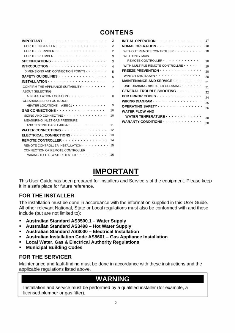
CONTENS
IMPORTANT・・・・・・・・・・・・・・・・・・・・・
FOR THE INSTALLER・・・・・・・・・・・・・・・・・
FOR THE SERVICER・・・・・・・・・・・・・・・・・
FOR THE PLUMBER・・・・・・・・・・・・・・・・・
SPECIFICATIONS・・・・・・・・・・・・・・・・・・
INTRODUCTION・・・・・・・・・・・・・・・・・・・
DIMENSIONS AND CONNECTION POINTS・・・・・・・
SAFETY GUIDELINES・・・・・・・・・・・・・・・・
INSTALLATION・・・・・・・・・・・・・・・・・・・
CONFIRM THE APPLIANCE SUITABILITY・・・・・・・・
ABOUT SELECTING
A INSTALLATION LOCATION・・・・・・・・・・・・
CLEARANCES FOR OUTDOOR
HEATER LOCATIONS – AS5601・・・・・・・・・・・
GAS CONNECTIONS・・・・・・・・・・・・・・・・
SIZING AND CONNECTING・・・・・・・・・・・・・・
MEASURING INLET GAS PRESSURE
AND TESTING GAS LEAKGAE・・・・・・・・・・・
WATER CONNECTIONS・・・・・・・・・・・・・・・
ELECTRICAL CONNECTIONS・・・・・・・・・・・・
REMOTE CONTROLLER・・・・・・・・・・・・・・・
REMOTE CONTROLLER INSTALLATION・・・・・・・・・
CONNECTION OF REMOTE CONTROLLER
WIRING TO THE WATER HEATER・・・・・・・・・・
2
2
2
3
3
4
5
6
7
7
8
9
10
10
11
12
13
14
15
16
INITIAL OPERATION・・・・・・・・・・・・・・・
NOMAL OPERATION・・・・・・・・・・・・・・・
WITHOUT REMOTE CONTROLLER・・・・・・・・・
WITH ONLY MAIN
REMOTE CONTROLLER・・・・・・・・・・・・
WITH MULTIPLE REMOTE CONTROLLRE・・・・・・
FREEZE PREVENTION・・・・・・・・・・・・・・
WINTER SHUTDOWN・・・・・・・・・・・・・・・
MAINTENANCE AND SERVICE・・・・・・・・・・
UNIT DRAINING and FILTER CLEANING・・・・・・・
GENERAL TROUBLE SHOOTING・・・・・・・・
PCB ERROR CODES・・・・・・・・・・・・・・・
WIRING DIAGRAM・・・・・・・・・・・・・・・・
OPERATING SAFETY・・・・・・・・・・・・・・・
WATER FLOW AND
WATER TENPERATURE・・・・・・・・・・・・
WARANTY CONDITIONS・・・・・・・・・・・・・
17
18
18
18
19
20
20
21
21
22
24
25
26
28
28
IMPORTANT This User Guide has been prepared for Installers and Servicers of the equipment. Please keep it in a safe place for future reference. FOR THE INSTALLER The installation must be done in accordance with the information supplied in this User Guide. All other relevant National, State or Local regulations must also be conformed with and these include (but are not limited to): Australian Standard AS3500.1 – Water Supply Australian Standard AS3498 – Hot Water Supply Australian Standard AS3000 – Electrical Installation Australian Installation Code AS5601 – Gas Appliance Installation Local Water, Gas & Electrical Authority Regulations Municipal Building Codes FOR THE SERVICER Maintenance and fault-finding must be done in accordance with these instructions and the applicable regulations listed above.
@@@@@@@@@@@WARNING@@@@@@@@@@@ Installation and service must be performed by a qualified installer (for example, a licensed plumber or gas fitter).
3
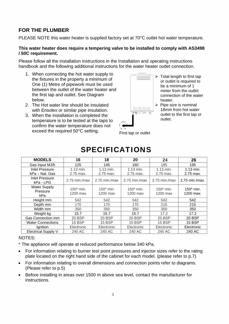
FOR THE PLUMBER PLEASE NOTE this water heater is supplied factory set at 70°C outlet hot water temperature. This water heater does require a tempering valve to be installed to comply with AS3498 / 50C requirement. Please follow all the installation instructions in the Installation and operating instructions handbook and the following additional instructions for the water heater outlet connection.
1. When connecting the hot water supply to
the fixtures in the property a minimum of One (1) Metre of pipework must be used between the outlet of the water heater and the first tap and outlet. See Diagram below.
2. The Hot water line should be insulated with Ensolex or similar pipe insulation.
3. When the installation is completed the temperature is to be tested at the taps to confirm the water temperature does not exceed the required 50°C setting.
SPECIFICATIONS
MODELS 16 18 20 24 26
Gas Input MJ/h 125 145 160 185 195 Inlet Pressure
kPa – Nat. Gas 1.13 min. 2.75 max.
1.13 min. 2.75 max.
1.13 min. 2.75 max.
1.13 min. 2.75 max.
1.13 min. 2.75 max.
Inlet Pressure kPa - LPG
2.75 min./max 2.75 min./max 2.75 min./max 2.75 min./max 2.75 min./max.
Water Supply Pressure
kPa
150* min. 1200 max
150* min. 1200 max
150* min. 1200 max
150* min. 1200 max
150* min. 1200 max.
Height mm 542 542 542 542 542 Depth mm 170 170 170 215 215 Width mm 350 350 350 350 350 Weight kg 15.7 15.7 15.7 17.2 17.2
Gas Connection mm 20 BSP 20 BSP 20 BSP 20 BSP 20 BSP Water Connections 15 BSP 15 BSP 15 BSP 15 BSP 15 BSP
Ignition Electronic Electronic Electronic Electronic Electronic Electrical Supply V 240 AC 240 AC 240 AC 240 AC 240 AC
NOTES: * The appliance will operate at reduced performance below 340 kPa. For information relating to burner test point pressures and injector sizes refer to the rating
plate located on the right hand side of the cabinet for each model. (please refer to p.7) For information relating to overall dimensions and connection points refer to diagrams.
(Please refer to p.5) Before installing in areas over 1500 m above sea level, contact the manufacturer for
instructions.
Total length to first tap or outlet is required to be a minimum of 1 meter from the outlet connection of the water heater.
Pipe size is nominal 18mm from hot water outlet to the first tap or outlet.
First tap or outlet

4
INTRODUCTION
This manual provides information necessary for the installation, operation, and maintenance of the water heater.
The model description is listed on the rating plate which is attached to the right side of
the case of the water heater. (Please refer to p.7) Please read all installation instructions completely before installing this product. The Water Heater is an instantaneous, tankless water heater designed to efficiently
supply endless hot water for your needs. The principle behind the water heater is simple:
Burner
Heat exchangerExhaust
Flow sensor
ThermistorComputerboard
AC240V
Gas valve
Fan
Cold water inlet
Gas
Hot water outlet
1. A hot water tap is turned on.
2. Water enters the heater.
3. The water flow sensor detects the water flow.
4. The computer automatically ignites the burner.
5. Water circulates through the heat exchanger and then gets hot.
6. The computer will modulate the gas supply valve and water flow to produce the right amount of hot water at the correct temperature.
7. When the tap is turned off, the unit shuts down.
※ This diagram illustrates the
w a t e r h e a t e r d e s i g n concepts only and is not a c c u r a t e t o t h e o n e p h y s i c a l d e s c r i p t i o n .
5
GAS
COLD
HOT
GASHOT
COLD
133 124
47 GAS
330
350
520
490
37
198
60
94
335
79
19
41 HOT
49 COLD
170
15.7
542
137
31 POWER
POWER
46:COLD
86:GAS
114:HOT
124:POWER
34
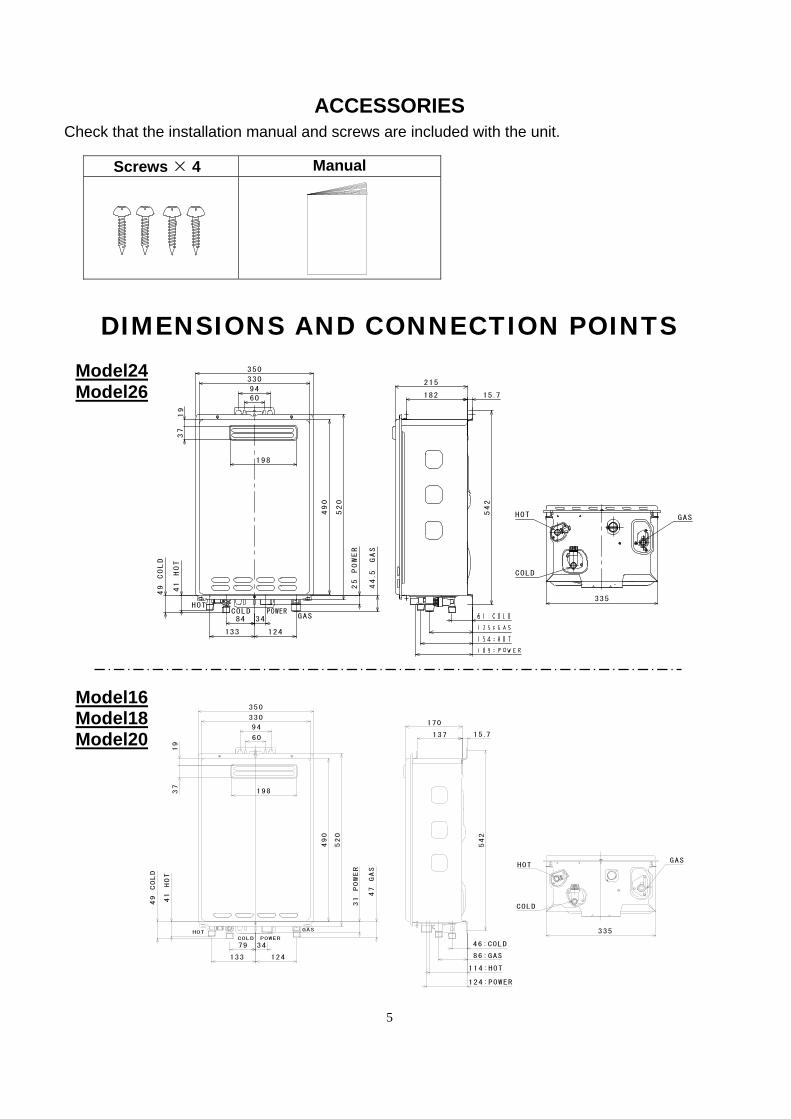
ACCESSORIES Check that the installation manual and screws are included with the unit.
Screws × 4 Manual
DIMENSIONS AND CONNECTION POINTS
GASCOLD
HOT
GASHOT
COLD
19
37
330
350
490
124133
335
44.5
GAS
520
41 HOT
49 COLD
1 98
60
94215
182
542
15.7
84 34POWER
25 POWER
Model24 Model26
Model16 Model18 Model20
6
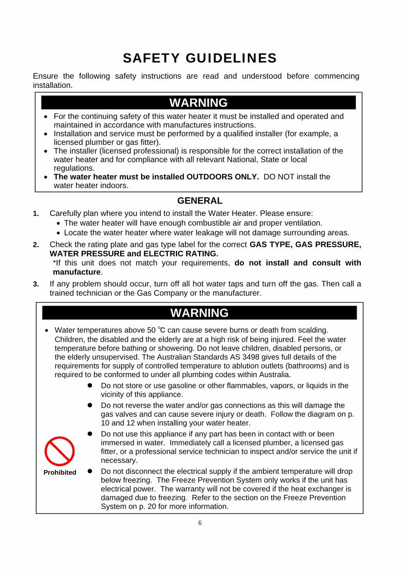
SAFETY GUIDELINES
Ensure the following safety instructions are read and understood before commencing installation.
GENERAL 1. Carefully plan where you intend to install the Water Heater. Please ensure:
The water heater will have enough combustible air and proper ventilation. Locate the water heater where water leakage will not damage surrounding areas.
2. Check the rating plate and gas type label for the correct GAS TYPE, GAS PRESSURE, WATER PRESSURE and ELECTRIC RATING. *If this unit does not match your requirements, do not install and consult with manufacture.
3. If any problem should occur, turn off all hot water taps and turn off the gas. Then call a trained technician or the Gas Company or the manufacturer.
@@@@@@@@@@@WARNING@@@@@@@@@@@ For the continuing safety of this water heater it must be installed and operated and
maintained in accordance with manufactures instructions. Installation and service must be performed by a qualified installer (for example, a
licensed plumber or gas fitter). The installer (licensed professional) is responsible for the correct installation of the
water heater and for compliance with all relevant National, State or local regulations.
The water heater must be installed OUTDOORS ONLY. DO NOT install the water heater indoors.
@@@@@@@@@@@WARNING@@@@@@@@@@@ Water temperatures above 50 ℃ can cause severe burns or death from scalding.
Children, the disabled and the elderly are at a high risk of being injured. Feel the water temperature before bathing or showering. Do not leave children, disabled persons, or the elderly unsupervised. The Australian Standards AS 3498 gives full details of the requirements for supply of controlled temperature to ablution outlets (bathrooms) and is required to be conformed to under all plumbing codes within Australia.
Do not store or use gasoline or other flammables, vapors, or liquids in the vicinity of this appliance.
Do not reverse the water and/or gas connections as this will damage the gas valves and can cause severe injury or death. Follow the diagram on p. 10 and 12 when installing your water heater.
Do not use this appliance if any part has been in contact with or been immersed in water. Immediately call a licensed plumber, a licensed gas fitter, or a professional service technician to inspect and/or service the unit if necessary.
Do not disconnect the electrical supply if the ambient temperature will drop below freezing. The Freeze Prevention System only works if the unit has electrical power. The warranty will not be covered if the heat exchanger is damaged due to freezing. Refer to the section on the Freeze Prevention System on p. 20 for more information.
Prohibited
7
INSTALLATION
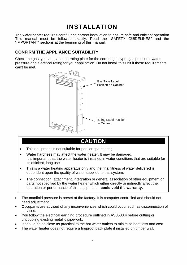
The water heater requires careful and correct installation to ensure safe and efficient operation. This manual must be followed exactly. Read the “SAFETY GUIDELINES” and the “IMPORTANT” sections at the beginning of this manual. CONFIRM THE APPLIANCE SUITABILITY Check the gas type label and the rating plate for the correct gas type, gas pressure, water pressure and electrical rating for your application. Do not install this unit if these requirements can’t be met.
The manifold pressure is preset at the factory. It is computer controlled and should not
need adjustment. Occupants are advised of any inconveniences which could occur such as disconnection of
services. You follow the electrical earthing procedure outlined in AS3500.4 before cutting or
uncoupling existing metallic pipework. It should be as close as practical to the hot water outlets to minimise heat loss and cost. The water heater does not require a fireproof back plate if installed on timber wall.
Rating Label Position on Cabinet
Gas Type Label Position on Cabinet
@@@@@@@@@@@CAUTION@@@@@@@@@@@
This equipment is not suitable for pool or spa heating. Water hardness may affect the water heater. It may be damaged.
It is important that the water heater is installed in water conditions that are suitable for its efficient, long use.
This is a water heating apparatus only and the final fitness of water delivered is dependent upon the quality of water supplied to this system.
The connection, attachment, integration or general association of other equipment or parts not specified by the water heater which either directly or indirectly affect the operation or performance of this equipment – could void the warranty.
8
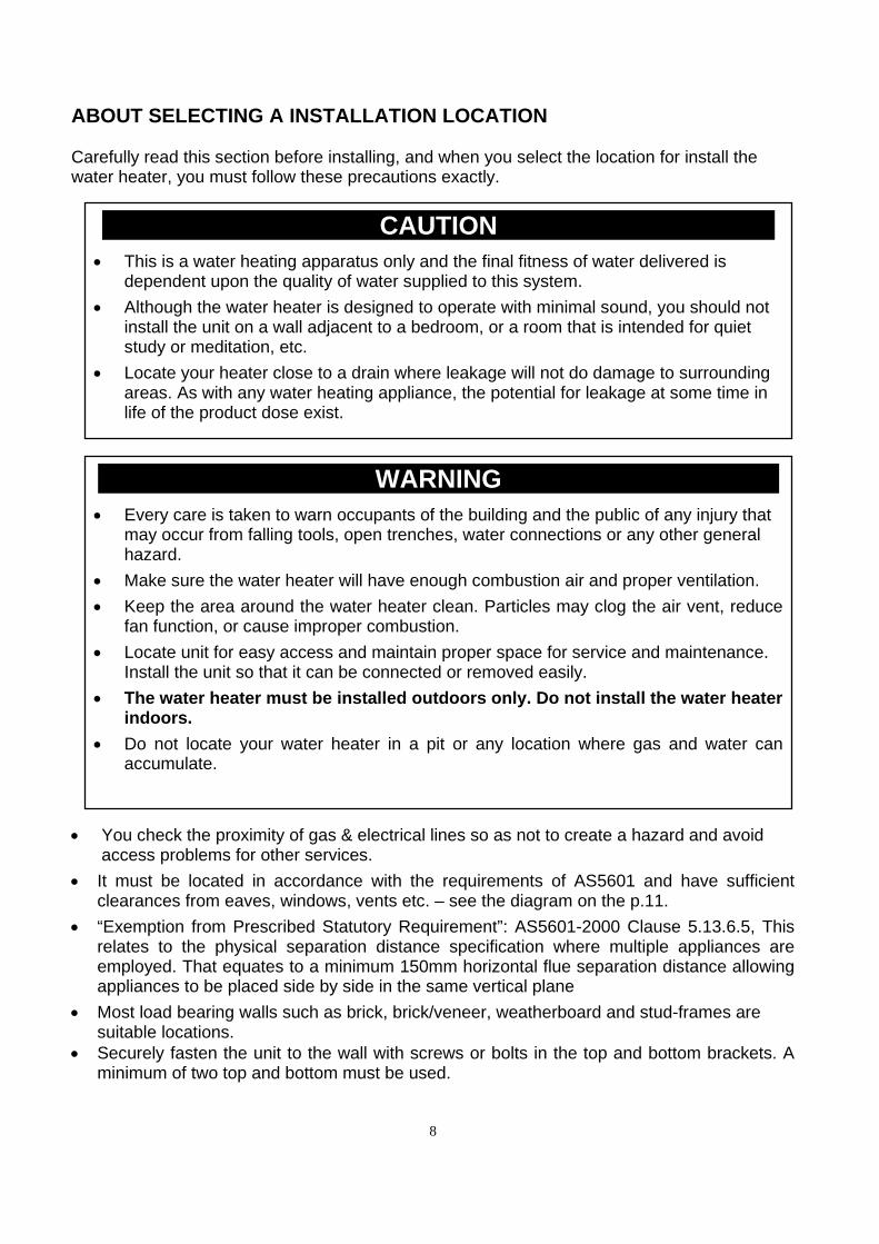
ABOUT SELECTING A INSTALLATION LOCATION Carefully read this section before installing, and when you select the location for install the water heater, you must follow these precautions exactly.
You check the proximity of gas & electrical lines so as not to create a hazard and avoid
access problems for other services. It must be located in accordance with the requirements of AS5601 and have sufficient
clearances from eaves, windows, vents etc. – see the diagram on the p.11. “Exemption from Prescribed Statutory Requirement”: AS5601-2000 Clause 5.13.6.5, This
relates to the physical separation distance specification where multiple appliances are employed. That equates to a minimum 150mm horizontal flue separation distance allowing appliances to be placed side by side in the same vertical plane
Most load bearing walls such as brick, brick/veneer, weatherboard and stud-frames are suitable locations.
Securely fasten the unit to the wall with screws or bolts in the top and bottom brackets. A minimum of two top and bottom must be used.
@@@@@@@@@@@CAUTION@@@@@@@@@@@ This is a water heating apparatus only and the final fitness of water delivered is
dependent upon the quality of water supplied to this system. Although the water heater is designed to operate with minimal sound, you should not
install the unit on a wall adjacent to a bedroom, or a room that is intended for quiet study or meditation, etc.
Locate your heater close to a drain where leakage will not do damage to surrounding areas. As with any water heating appliance, the potential for leakage at some time in life of the product dose exist.
@@@@@@@@@@@WARNING@@@@@@@@@@@ Every care is taken to warn occupants of the building and the public of any injury that
may occur from falling tools, open trenches, water connections or any other general hazard.
Make sure the water heater will have enough combustion air and proper ventilation. Keep the area around the water heater clean. Particles may clog the air vent, reduce
fan function, or cause improper combustion. Locate unit for easy access and maintain proper space for service and maintenance.
Install the unit so that it can be connected or removed easily. The water heater must be installed outdoors only. Do not install the water heater
indoors. Do not locate your water heater in a pit or any location where gas and water can
accumulate.
9
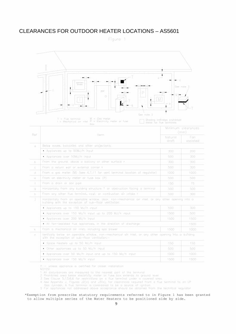
CLEARANCES FOR OUTDOOR HEATER LOCATIONS – AS5601 *Exemption from prescribe statutory requirements referred to in Figure 1 has been granted
to allow multiple series of the Water Heaters to be positioned side by side.
10
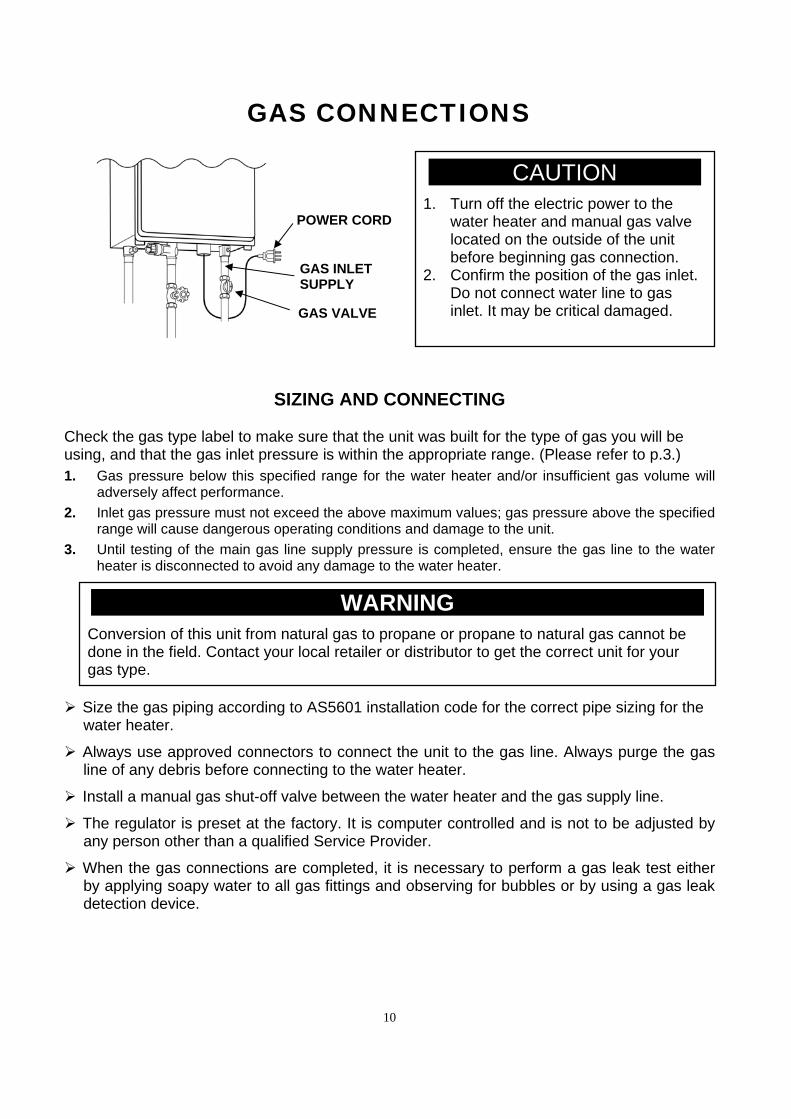
GAS CONNECTIONS
SIZING AND CONNECTING
Check the gas type label to make sure that the unit was built for the type of gas you will be using, and that the gas inlet pressure is within the appropriate range. (Please refer to p.3.) 1. Gas pressure below this specified range for the water heater and/or insufficient gas volume will
adversely affect performance. 2. Inlet gas pressure must not exceed the above maximum values; gas pressure above the specified
range will cause dangerous operating conditions and damage to the unit. 3. Until testing of the main gas line supply pressure is completed, ensure the gas line to the water
heater is disconnected to avoid any damage to the water heater. Size the gas piping according to AS5601 installation code for the correct pipe sizing for the
water heater. Always use approved connectors to connect the unit to the gas line. Always purge the gas
line of any debris before connecting to the water heater. Install a manual gas shut-off valve between the water heater and the gas supply line. The regulator is preset at the factory. It is computer controlled and is not to be adjusted by
any person other than a qualified Service Provider. When the gas connections are completed, it is necessary to perform a gas leak test either
by applying soapy water to all gas fittings and observing for bubbles or by using a gas leak detection device.
GAS INLET SUPPLY
POWER CORD
GAS VALVE
a@@@CAUTION@@@a 1. Turn off the electric power to the
water heater and manual gas valve located on the outside of the unit before beginning gas connection.
2. Confirm the position of the gas inlet. Do not connect water line to gas inlet. It may be critical damaged.
@@@@@@@@@@@WARNING@@@@@@@@@@@ Conversion of this unit from natural gas to propane or propane to natural gas cannot be done in the field. Contact your local retailer or distributor to get the correct unit for your gas type.
11
MEASURING INLET GAS PRESSURE AND TESTING GAS LEAKGAE
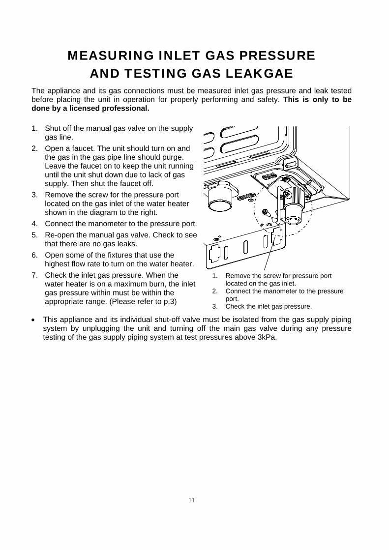
The appliance and its gas connections must be measured inlet gas pressure and leak tested before placing the unit in operation for properly performing and safety. This is only to be done by a licensed professional.
1. Shut off the manual gas valve on the supply gas line.
2. Open a faucet. The unit should turn on and the gas in the gas pipe line should purge. Leave the faucet on to keep the unit running until the unit shut down due to lack of gas supply. Then shut the faucet off.
3. Remove the screw for the pressure port located on the gas inlet of the water heater shown in the diagram to the right.
4. Connect the manometer to the pressure port.
5. Re-open the manual gas valve. Check to see that there are no gas leaks.
6. Open some of the fixtures that use the highest flow rate to turn on the water heater.
7. Check the inlet gas pressure. When the water heater is on a maximum burn, the inlet gas pressure within must be within the appropriate range. (Please refer to p.3)
This appliance and its individual shut-off valve must be isolated from the gas supply piping
system by unplugging the unit and turning off the main gas valve during any pressure testing of the gas supply piping system at test pressures above 3kPa.
1. Remove the screw for pressure port located on the gas inlet.
2. Connect the manometer to the pressure port.
3. Check the inlet gas pressure.

12
WATER CONNECTIONS
All pipes, pipe fittings, valves and other components, including soldering materials, must be suitable for potable water systems.
A manual shut off valve must be installed on the cold water inlet to the water heater between the main water supply line and the water heater.
Only a gate valve or a ball valve is to be used on the cold water supply. No stop taps or check valves are to be used as this will void the warranty and damage the
water heater. Check the cold water pressure and if above 1000 kPa an approved limiting valve must be
fitted.
Before installing the water heater, flush the water line to remove all debris, and after installation is complete, purge the air from the line. Failure to do so may cause damage to the heater.
There is a wire mesh filter to discourage debris from entering your heater. Clean filter after initial installation to ensure no debris from the pipe work has clogged it.
NOTE: This filter must be cleaned as part of regular maintenance.
HOT WATER OUTLET COLD WATER
INLET
DRAIN PLUG
FILTER
GATE OR BALL VALVE ON INLET
1. TURN OFF THE WATER INLET SUPPLY VALVE.
2. OPEN A HOT WATER TAP TO RELEASE THE LINE P R E S S U R E .
R E M O V E B Y T U R N I N G COUNTERCLOCKWISE AND THEN CLEAN AND REPLACE
FILTER
@@WARNING@ @
Do not reverse the hot outlet and cold supply line connections to the Water Heater as this will cause your heater to operate improperly.
13
ELECTRICAL CONNECTIONS
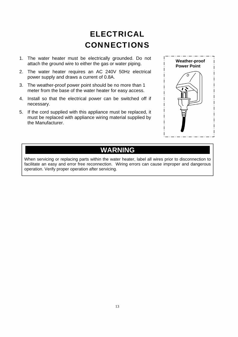
1. The water heater must be electrically grounded. Do not
attach the ground wire to either the gas or water piping. 2. The water heater requires an AC 240V 50Hz electrical
power supply and draws a current of 0.8A. 3. The weather-proof power point should be no more than 1
meter from the base of the water heater for easy access. 4. Install so that the electrical power can be switched off if
necessary. 5. If the cord supplied with this appliance must be replaced, it
must be replaced with appliance wiring material supplied by the Manufacturer.
@@@@@@@@@@@WARNING@@@@@@@@@@@ When servicing or replacing parts within the water heater, label all wires prior to disconnection to facilitate an easy and error free reconnection. Wiring errors can cause improper and dangerous operation. Verify proper operation after servicing.
Weather-proof Power Point

14
REMOTE CONTROLLER (OPTIONAL)
The water heater can be installed with up to three remote controllers. Each remote controller has two functions which can adjust the set temperature and indicate the error code on the remote controller. The set temperature can be adjusted only by remote controller which has the priority
setting (When remote controller has the priority setting, PRIORITY lamp on remote controller is lit), and the other remote controller(s) display the set temperature. If you desire to transfer the priority setting, you can transfer it by pressing PRIORITY button only when there is no water flow through the water heater. (Default set temperature is 40ºC)
All models water heater have self diagnostic function for safety and convenience when trouble shooting. If there is a problem with the installation or the unit, it will display a numerical error code on the remote controller (or the LED of the computer board will be blink.)
MAIN REMOTE CONTROLLER MODEL MC100-AU3 MC100-AU3 must be installed inside (such as kitchen)
due to NO water resistant. Be careful installation location.
It allows the output temperature from the water heater to be adjusted within the range of 37ºC to 55ºC.
The temperature options are: 37ºC, 38ºC, 39ºC, 40ºC, 41ºC, 42ºC, 43ºC, 44ºC, 45ºC, 46ºC, 47ºC, 50ºC, 55ºC.
When “BURNER ON” lamp is lit, the set temperature can not be adjusted to 55ºC. If you desire to set it to 55ºC, you should close the hot water tap.
MODEL FC100W-AU3 SHOWER CONTROLLER AND SC100-AU3 ENSUITE CONTROLLER FC100W-AU3 (Shower) and SC100-AU3 (Ensuite)
controllers are water resistant, however should not be positioned where can be splashed directly and there should be caulking between the surface of the wall and the controller.
FC100W-AU3 is installed such as the main bathroom, and SC100-AU3 is installed such as the ensuite bath room.
These remote controller allows the output temperature from the water heater to be adjust within the range of 37ºC to 50ºC.
The temperature options are: 37ºC, 38ºC, 39ºC, 40ºC, 41ºC, 42ºC, 43ºC, 44ºC, 45ºC, 46ºC, 47ºC, 50ºC.
When BURNER ON lamp is lit, the set temperature can not be adjusted to 42ºC or over. If you desire those temperatures, you should close the hot water tap.
PRIORITY
BURNER ON
ON/OFFPRIORITY
HOT
COOL
MADE IN JAPANMain
40
Main
Shower
PRIORITY
BURNER ON
ON/OFFPRIORITY
HOT
COOL
MADE IN JAPANShower
40
Ensuite
PRIORITY
BURNER ON
ON/OFFPRIORITY
HOT
COOL
MADE IN JAPANEnsuite
40
15
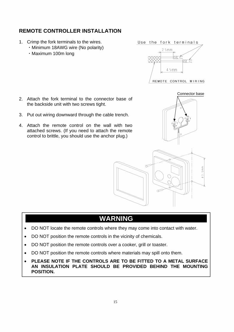
REMOTE CONTROLLER INSTALLATION 1. Crimp the fork terminals to the wires.
・Minimum 18AWG wire (No polarity) ・Maximum 100m long
2. Attach the fork terminal to the connector base of
the backside unit with two screws tight. 3. Put out wiring downward through the cable trench. 4. Attach the remote control on the wall with two
attached screws. (If you need to attach the remote control to brittle, you should use the anchor plug.)
Connector base
@@@@@@@@@@@WARNING@@@@@@@@@@@ DO NOT locate the remote controls where they may come into contact with water. DO NOT position the remote controls in the vicinity of chemicals. DO NOT position the remote controls over a cooker, grill or toaster. DO NOT position the remote controls where materials may spill onto them. PLEASE NOTE IF THE CONTROLS ARE TO BE FITTED TO A METAL SURFACE
AN INSULATION PLATE SHOULD BE PROVIDED BEHIND THE MOUNTING POSITION.
REMOTE CONTROL WIRING
Use the fork terminals
16
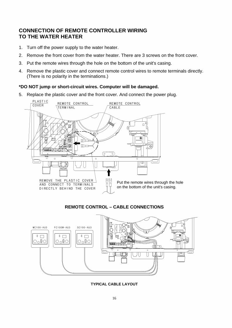
CONNECTION OF REMOTE CONTROLLER WIRING TO THE WATER HEATER 1. Turn off the power supply to the water heater. 2. Remove the front cover from the water heater. There are 3 screws on the front cover. 3. Put the remote wires through the hole on the bottom of the unit's casing. 4. Remove the plastic cover and connect remote control wires to remote terminals directly.
(There is no polarity in the terminations.)
*DO NOT jump or short-circuit wires. Computer will be damaged. 5. Replace the plastic cover and the front cover. And connect the power plug.
REMOTE CONTROL – CABLE CONNECTIONS
TYPICAL CABLE LAYOUT
1 2 3 4 5 6 7 8
PLASTICCOVER
REMOTE CONTROLCABLE
REMOTE CONTROL TERMINAL
REMOVE THE PLASTIC COVER AND CONNECT TO TERMINALSDIRECTLY BEHIND THE COVER
Put the remote wires through the hole on the bottom of the unit's casing.
1 2 3 4 5 6 7 8
MC100-AU3 SC100-AU3FC100W-AU3
17
INITIAL OPERATION
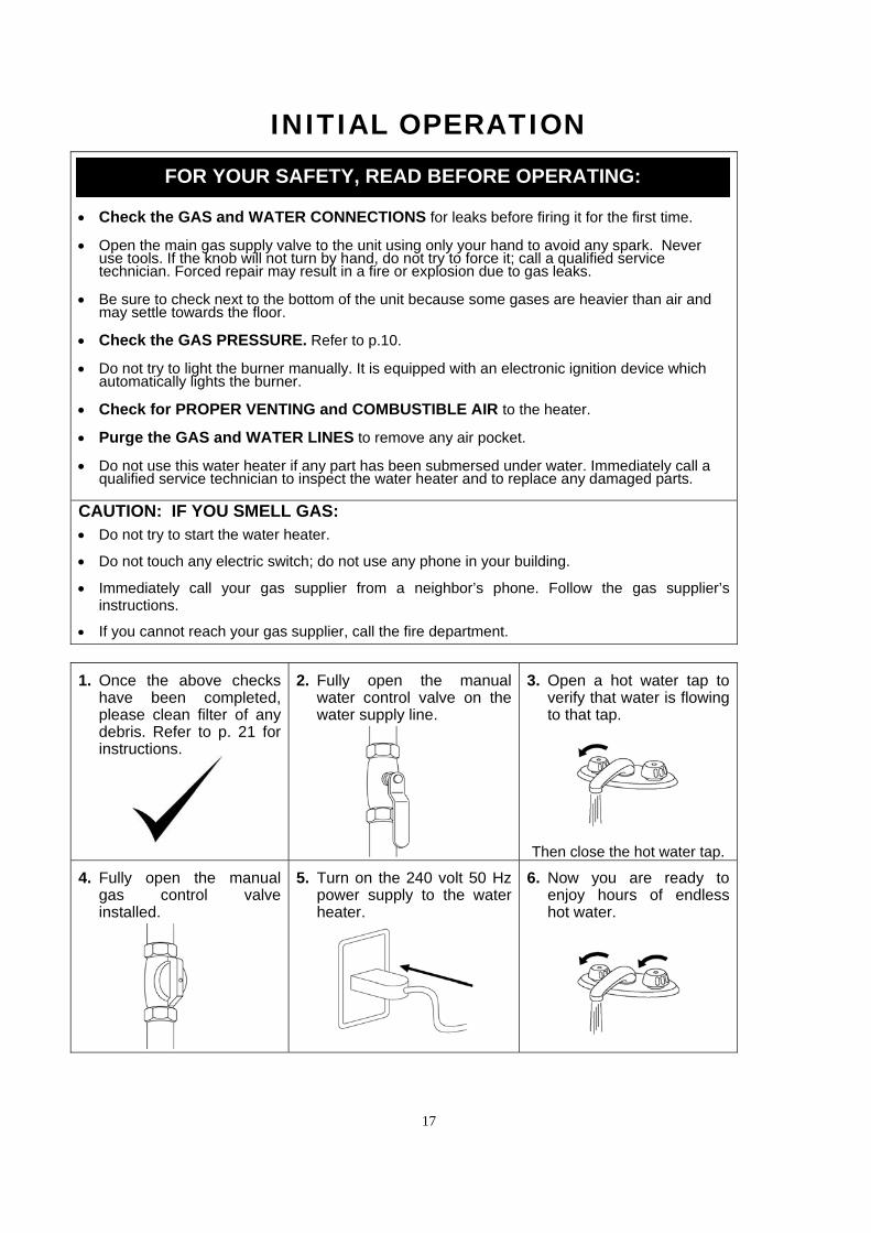
Check the GAS and WATER CONNECTIONS for leaks before firing it for the first time.
Open the main gas supply valve to the unit using only your hand to avoid any spark. Never use tools. If the knob will not turn by hand, do not try to force it; call a qualified service technician. Forced repair may result in a fire or explosion due to gas leaks.
Be sure to check next to the bottom of the unit because some gases are heavier than air and may settle towards the floor.
Check the GAS PRESSURE. Refer to p.10.
Do not try to light the burner manually. It is equipped with an electronic ignition device which automatically lights the burner.
Check for PROPER VENTING and COMBUSTIBLE AIR to the heater.
Purge the GAS and WATER LINES to remove any air pocket.
Do not use this water heater if any part has been submersed under water. Immediately call a qualified service technician to inspect the water heater and to replace any damaged parts.
CAUTION: IF YOU SMELL GAS: Do not try to start the water heater.
Do not touch any electric switch; do not use any phone in your building.
Immediately call your gas supplier from a neighbor’s phone. Follow the gas supplier’s instructions.
If you cannot reach your gas supplier, call the fire department.
1. Once the above checks have been completed, please clean filter of any debris. Refer to p. 21 for instructions.
2. Fully open the manual water control valve on the water supply line.
3. Open a hot water tap to verify that water is flowing to that tap.
Then close the hot water tap.
4. Fully open the manual gas control valve installed.
5. Turn on the 240 volt 50 Hz power supply to the water heater.
6. Now you are ready to enjoy hours of endless hot water.
FOR YOUR SAFETY, READ BEFORE OPERATING:
18
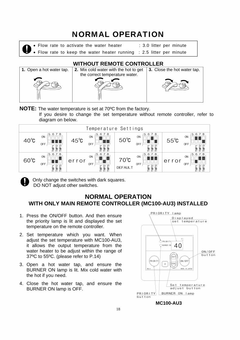
NORMAL OPERATION Flow rate to activate the water heater : 3.0 litter per minute
Flow rate to keep the water heater running : 2.5 litter per minute
WITHOUT REMOTE CONTROLLER 1. Open a hot water tap.
2. Mix cold water with the hot to get the correct temperature water.
3. Close the hot water tap.
NOTE: The water temperature is set at 70ºC from the factory.
If you desire to change the set temperature without remote controller, refer to diagram on below.
Only change the switches with dark squares.
DO NOT adjust other switches.
NORMAL OPERATION WITH ONLY MAIN REMOTE CONTROLLER (MC100-AU3) INSTALLED
1. Press the ON/OFF button. And then ensure
the priority lamp is lit and displayed the set temperature on the remote controller.
2. Set temperature which you want. When
adjust the set temperature with MC100-AU3, it allows the output temperature from the water heater to be adjust within the range of 37ºC to 55ºC. (please refer to P.14)
3. Open a hot water tap, and ensure the
BURNER ON lamp is lit. Mix cold water with the hot if you need.
4. Close the hot water tap, and ensure the
BURNER ON lamp is OFF.
MC100-AU3
PRIORITY
BURNER ON
ON/OFFPRIORITY
HOT
COOL
MADE IN JAPANMain
40ON/OFFbutton
Displayedset temperature
BURNER ON lamp
Set temperature adjust button
PRIORITYbutton
PRIORITY lamp
45℃40℃ 55℃50℃
error60℃ errorDEFAULT
Temperature Settings
OFF
ON5 6 7 8 5 6 7 8 5 6 7 85 6 7 8
OFF
ON
OFF
ON
OFF
ON
5 6 7 85 6 7 8 5 6 7 8
OFF
ON
OFF
ON
OFF
ON5 6 7 8
OFF
ON
70℃
TMP3
TMP2
TMP1
TMP3
TMP2
TMP1
TMP3
TMP2
TMP1
TMP3
TMP2
TMP1
TMP3
TMP2
TMP1
TMP3
TMP2
TMP1
TMP3
TMP2
TMP1
TMP3
TMP2
TMP1
19
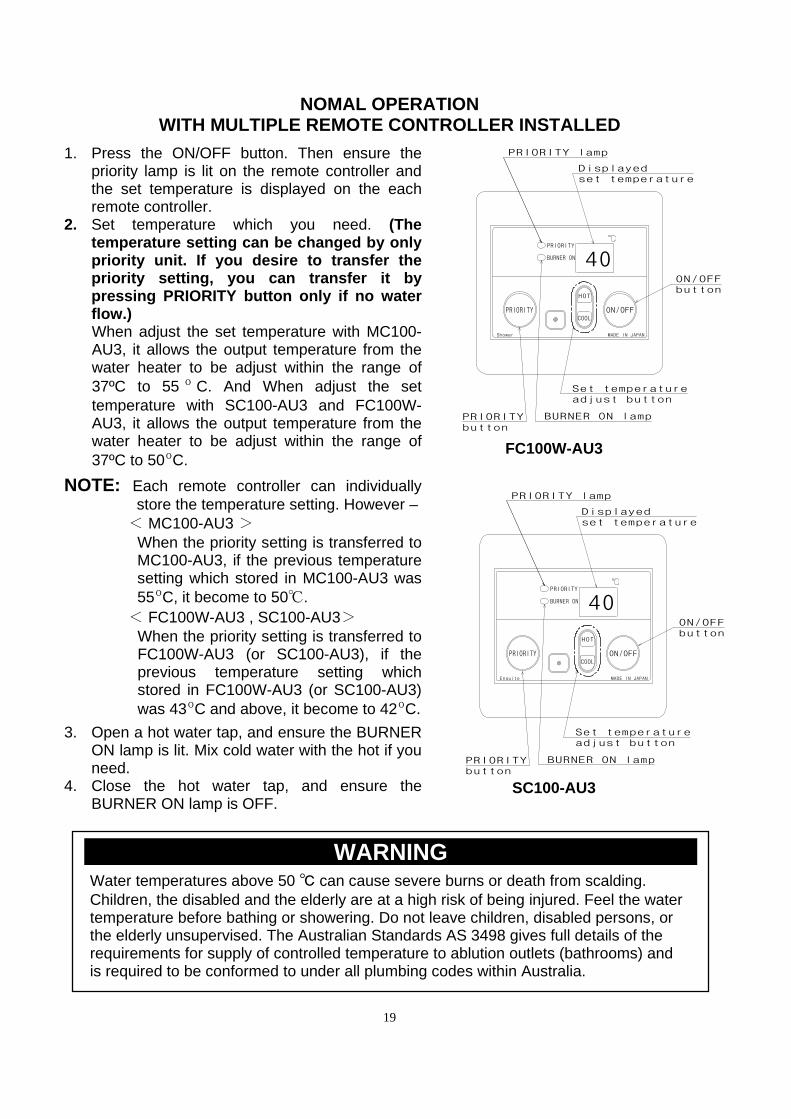
NOMAL OPERATION WITH MULTIPLE REMOTE CONTROLLER INSTALLED
1. Press the ON/OFF button. Then ensure the
priority lamp is lit on the remote controller and the set temperature is displayed on the each remote controller.
2. Set temperature which you need. (The temperature setting can be changed by only priority unit. If you desire to transfer the priority setting, you can transfer it by pressing PRIORITY button only if no water flow.) When adjust the set temperature with MC100-AU3, it allows the output temperature from the water heater to be adjust within the range of 37ºC to 55 º C. And When adjust the set temperature with SC100-AU3 and FC100W-AU3, it allows the output temperature from the water heater to be adjust within the range of 37ºC to 50ºC.
NOTE: Each remote controller can individually store the temperature setting. However –
< MC100-AU3 > When the priority setting is transferred to MC100-AU3, if the previous temperature setting which stored in MC100-AU3 was 55ºC, it become to 50℃.
< FC100W-AU3 , SC100-AU3> When the priority setting is transferred to FC100W-AU3 (or SC100-AU3), if the previous temperature setting which stored in FC100W-AU3 (or SC100-AU3) was 43ºC and above, it become to 42ºC.
3. Open a hot water tap, and ensure the BURNER ON lamp is lit. Mix cold water with the hot if you need.
4. Close the hot water tap, and ensure the BURNER ON lamp is OFF.
@@@@@@@@@@@WARNING@@@@@@@@@@@ Water temperatures above 50 ℃ can cause severe burns or death from scalding. Children, the disabled and the elderly are at a high risk of being injured. Feel the water temperature before bathing or showering. Do not leave children, disabled persons, or the elderly unsupervised. The Australian Standards AS 3498 gives full details of the requirements for supply of controlled temperature to ablution outlets (bathrooms) and is required to be conformed to under all plumbing codes within Australia.
FC100W-AU3
SC100-AU3
PRIORITY
BURNER ON
ON/OFFPRIORITY
HOT
COOL
MADE IN JAPANShower
40ON/OFFbutton
Displayedset temperature
BURNER ON lamp
Set temperature adjust button
PRIORITYbutton
PRIORITY lamp
PRIORITY
BURNER ON
ON/OFFPRIORITY
HOT
COOL
MADE IN JAPANEnsuite
40ON/OFFbutton
Displayedset temperature
BURNER ON lamp
Set temperature adjust button
PRIORITYbutton
PRIORITY lamp
20
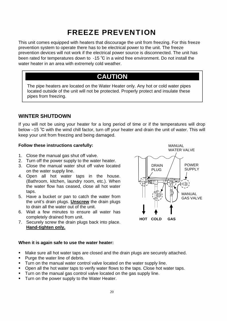
FREEZE PREVENTION This unit comes equipped with heaters that discourage the unit from freezing. For this freeze prevention system to operate there has to be electrical power to the unit. The freeze prevention devices will not work if the electrical power source is disconnected. The unit has been rated for temperatures down to -15 ℃ in a wind free environment. Do not install the water heater in an area with extremely cold weather. WINTER SHUTDOWN If you will not be using your heater for a long period of time or if the temperatures will drop below –15 ℃ with the wind chill factor, turn off your heater and drain the unit of water. This will keep your unit from freezing and being damaged. Follow these instructions carefully: 1. Close the manual gas shut off valve. 2. Turn off the power supply to the water heater. 3. Close the manual water shut off valve located
on the water supply line. 4. Open all hot water taps in the house.
(Bathroom, kitchen, laundry room, etc.). When the water flow has ceased, close all hot water taps.
5. Have a bucket or pan to catch the water from the unit’s drain plugs. Unscrew the drain plugs to drain all the water out of the unit.
6. Wait a few minutes to ensure all water has completely drained from unit.
7. Securely screw the drain plugs back into place. Hand-tighten only.
When it is again safe to use the water heater: Make sure all hot water taps are closed and the drain plugs are securely attached. Purge the water line of debris. Turn on the manual water control valve located on the water supply line. Open all the hot water taps to verify water flows to the taps. Close hot water taps. Turn on the manual gas control valve located on the gas supply line. Turn on the power supply to the Water Heater.
GAS COLD HOT
@@@@@@@@@@@CAUTION@@@@@@@@@@@
The pipe heaters are located on the Water Heater only. Any hot or cold water pipes located outside of the unit will not be protected. Properly protect and insulate these pipes from freezing.
POWER SUPPLY
MANUAL GAS VALVE
MANUAL WATER VALVE
DRAIN PLUG
21
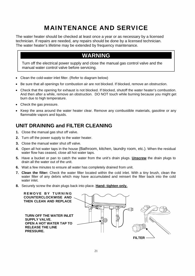
MAINTENANCE AND SERVICE The water heater should be checked at least once a year or as necessary by a licensed technician. If repairs are needed, any repairs should be done by a licensed technician. The water heater’s lifetime may be extended by frequency maintenance.
Clean the cold-water inlet filter. (Refer to diagram below)
Be sure that all openings for combustion air are not blocked. If blocked, remove an obstruction.
Check that the opening for exhaust is not blocked. If blocked, shutoff the water heater’s combustion. And then after a while, remove an obstruction. DO NOT touch while burning because you might get burn due to high temperature.
Check the gas pressure.
Keep the area around the water heater clear. Remove any combustible materials, gasoline or any flammable vapors and liquids.
UNIT DRAINING and FILTER CLEANING 1. Close the manual gas shut off valve.
2. Turn off the power supply to the water heater.
3. Close the manual water shut off valve.
4. Open all hot water taps in the house (Bathroom, kitchen, laundry room, etc.). When the residual water flow has ceased, close all hot water taps.
5. Have a bucket or pan to catch the water from the unit’s drain plugs. Unscrew the drain plugs to drain all the water out of the unit.
6. Wait a few minutes to ensure all water has completely drained from unit.
7. Clean the filter: Check the water filter located within the cold inlet. With a tiny brush, clean the water filter of any debris which may have accumulated and reinsert the filter back into the cold water inlet.
8. Securely screw the drain plugs back into place. Hand- tighten only.
@@@@@@@@@@@WARNING@@@@@@@@@@@
Turn off the electrical power supply and close the manual gas control valve and the manual water control valve before servicing.
TURN OFF THE WATER INLET SUPPLY VALVE. OPEN A HOT WATER TAP TO RELEASE THE LINE PRESSURE.
R E M O V E B Y T U R N I N G COUNTERCLOCKWISE AND THEN CLEAN AND REPLACE
FILTER
22
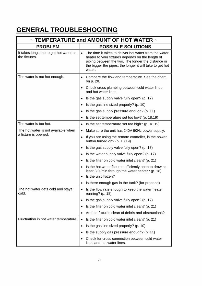
GENERAL TROUBLESHOOTING
~ TEMPERATURE and AMOUNT OF HOT WATER ~ PROBLEM POSSIBLE SOLUTIONS
It takes long time to get hot water at the fixtures.
The time it takes to deliver hot water from the water heater to your fixtures depends on the length of piping between the two. The longer the distance or the bigger the pipes, the longer it will take to get hot water.
The water is not hot enough.
Compare the flow and temperature. See the chart on p. 28.
Check cross plumbing between cold water lines and hot water lines.
Is the gas supply valve fully open? (p. 17)
Is the gas line sized properly? (p. 10)
Is the gas supply pressure enough? (p. 11)
Is the set temperature set too low? (p. 18,19)
The water is too hot. Is the set temperature set too high? (p. 18,19)
The hot water is not available when a fixture is opened.
Make sure the unit has 240V 50Hz power supply.
If you are using the remote controller, is the power button turned on? (p. 18,19)
Is the gas supply valve fully open? (p. 17)
Is the water supply valve fully open? (p. 17)
Is the filter on cold water inlet clean? (p. 21)
Is the hot water fixture sufficiently open to draw at least 3.0l/min through the water heater? (p. 18)
Is the unit frozen?
Is there enough gas in the tank? (for propane)
The hot water gets cold and stays cold.
Is the flow rate enough to keep the water heater running? (p. 18)
Is the gas supply valve fully open? (p. 17)
Is the filter on cold water inlet clean? (p. 21)
Are the fixtures clean of debris and obstructions?
Fluctuation in hot water temperature.
Is the filter on cold water inlet clean? (p. 21)
Is the gas line sized properly? (p. 10)
Is the supply gas pressure enough? (p. 11)
Check for cross connection between cold water lines and hot water lines.
23
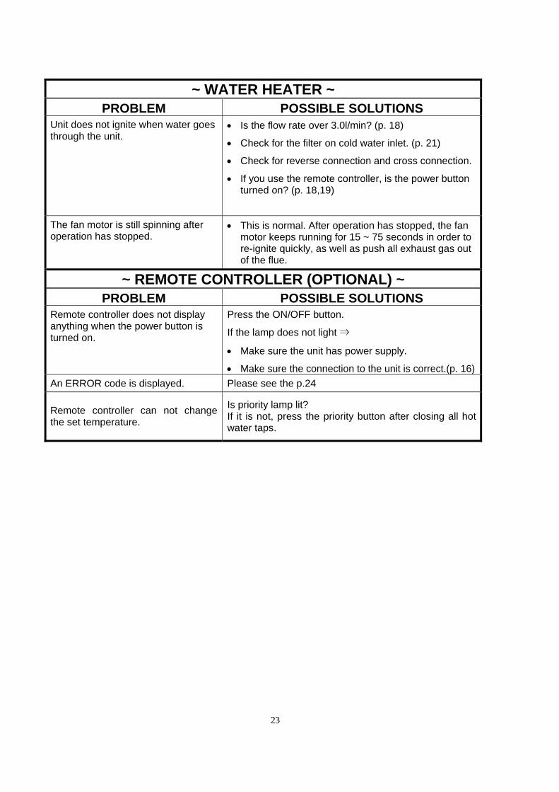
~ WATER HEATER ~ PROBLEM POSSIBLE SOLUTIONS
Unit does not ignite when water goes through the unit.
Is the flow rate over 3.0l/min? (p. 18)
Check for the filter on cold water inlet. (p. 21)
Check for reverse connection and cross connection.
If you use the remote controller, is the power button turned on? (p. 18,19)
The fan motor is still spinning after operation has stopped.
This is normal. After operation has stopped, the fan motor keeps running for 15 ~ 75 seconds in order to re-ignite quickly, as well as push all exhaust gas out of the flue.
~ REMOTE CONTROLLER (OPTIONAL) ~ PROBLEM POSSIBLE SOLUTIONS
Remote controller does not display anything when the power button is turned on.
Press the ON/OFF button.
If the lamp does not light ⇒
Make sure the unit has power supply.
Make sure the connection to the unit is correct.(p. 16)
An ERROR code is displayed. Please see the p.24
Remote controller can not change the set temperature.
Is priority lamp lit? If it is not, press the priority button after closing all hot water taps.
24
1 2 3 4 5 6 7 8
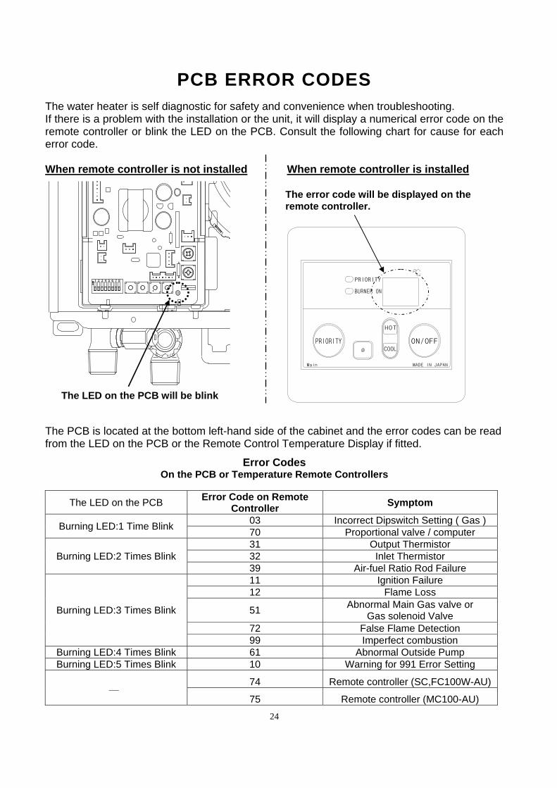
PCB ERROR CODES The water heater is self diagnostic for safety and convenience when troubleshooting. If there is a problem with the installation or the unit, it will display a numerical error code on the remote controller or blink the LED on the PCB. Consult the following chart for cause for each error code. When remote controller is not installed When remote controller is installed
The PCB is located at the bottom left-hand side of the cabinet and the error codes can be read from the LED on the PCB or the Remote Control Temperature Display if fitted.
Error Codes On the PCB or Temperature Remote Controllers
The LED on the PCB Error Code on Remote
Controller Symptom
Burning LED:1 Time Blink 03 Incorrect Dipswitch Setting ( Gas ) 70 Proportional valve / computer
Burning LED:2 Times Blink 31 Output Thermistor 32 Inlet Thermistor 39 Air-fuel Ratio Rod Failure
Burning LED:3 Times Blink
11 Ignition Failure 12 Flame Loss
51 Abnormal Main Gas valve or
Gas solenoid Valve 72 False Flame Detection 99 Imperfect combustion
Burning LED:4 Times Blink 61 Abnormal Outside Pump Burning LED:5 Times Blink 10 Warning for 991 Error Setting
― 74 Remote controller (SC,FC100W-AU)
75 Remote controller (MC100-AU)
The LED on the PCB will be blink
The error code will be displayed on the remote controller.
PRIORITY
BURNER ON
ON/OFFPRIORITY
HOT
COOL
MADE IN JAPANMain

25
WIRING DIAGRAM
NOTE: Only change black color switches. Don't touch the other switches.
IGElect rod
W
YBL
O
R
FM
RemoteController
654321
FlowAdjust mentValve
3477
OFF
P
P
7 8
Inletthermistor
Mixing thermistor
Burning LED
GasPropor-tional Valve
Flame rod Ground
Air-fuel ratio rod
FlowSensor
3
9
53
73
MV
SV3
SV2
SV1
LBGOR
O.H.C.F
Hi-limitswitch
BLBLBL
BL
BL
Only
BLBLPK
PK
C
18
17
10
+
6564+85-
RWBK
BK
BK
BK
BK
BK
R
R
W
YGO
Trans-former
BKW
Increase button
Decrease button MAX button
MIN button
Dipswitches
Ground
BKW
Fuse 5A
PCB
Model 26Model 24
Heater
Thermostat
Heater
W
W
BK
BK
BK
W
W
W
240 VAC Ground
BR
BL
Y&G
BKW
BKW
BK
W
BK
W
MAIN PCBGS00W-AU
W WHITE
R RED
BK BLACK
P PURPLE
LB LIGHT BLUE
BL BLUE
G GREEN
Y YELLOW
O ORANGE
BR BROWN
PK PINK
45℃40℃
55℃50℃
error60℃
errorDEFAULT
Temperature Settings
OFF
ON5 6 7 8 5 6 7 8
5 6 7 85 6 7 8
OFF
ON
OFF
ON
OFF
ON
5 6 7 85 6 7 8
5 6 7 8
OFF
ON
OFF
ON
OFF
ON5 6 7 8
OFF
ON
70℃
TMP3
TMP2
TMP1
TMP3
TMP2
TMP1
TMP3
TMP2
TMP1
TMP3
TMP2
TMP1
TMP3
TMP2
TMP1
TMP3
TMP2
TMP1
TMP3
TMP2
TMP1
TMP3
TMP2
TMP1
Gas type
Propane
Natural Gas
OFF
ON1 2 3
1 2 3
OFF
ON
26
OPERATING SAFETY
FOR YOUR SAFETY READ BEFORE OPERATING
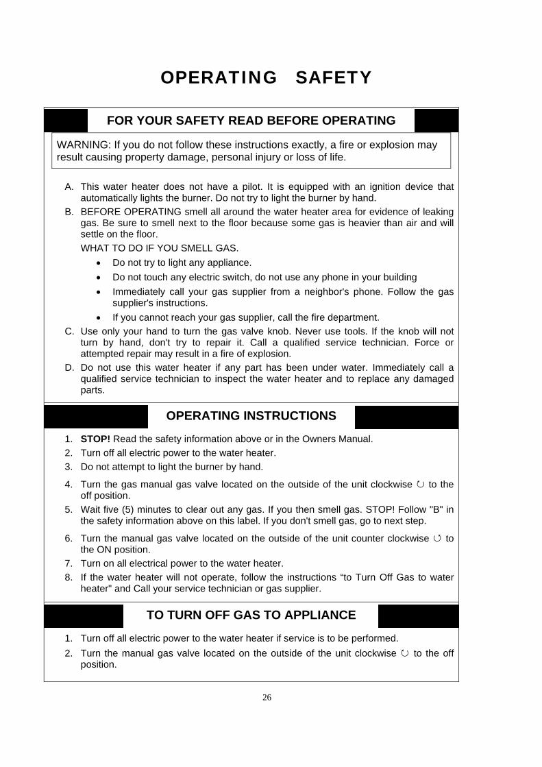
WARNING: If you do not follow these instructions exactly, a fire or explosion may result causing property damage, personal injury or loss of life.
A. This water heater does not have a pilot. It is equipped with an ignition device that
automatically lights the burner. Do not try to light the burner by hand.
B. BEFORE OPERATING smell all around the water heater area for evidence of leaking gas. Be sure to smell next to the floor because some gas is heavier than air and will settle on the floor.
WHAT TO DO IF YOU SMELL GAS.
Do not try to light any appliance.
Do not touch any electric switch, do not use any phone in your building
Immediately call your gas supplier from a neighbor's phone. Follow the gas supplier's instructions.
If you cannot reach your gas supplier, call the fire department.
C. Use only your hand to turn the gas valve knob. Never use tools. If the knob will not turn by hand, don't try to repair it. Call a qualified service technician. Force or attempted repair may result in a fire of explosion.
D. Do not use this water heater if any part has been under water. Immediately call a qualified service technician to inspect the water heater and to replace any damaged parts.
OPERATING INSTRUCTIONS
1. STOP! Read the safety information above or in the Owners Manual.
2. Turn off all electric power to the water heater.
3. Do not attempt to light the burner by hand.
4. Turn the gas manual gas valve located on the outside of the unit clockwise ↻ to the off position.
5. Wait five (5) minutes to clear out any gas. If you then smell gas. STOP! Follow "B" in the safety information above on this label. If you don't smell gas, go to next step.
6. Turn the manual gas valve located on the outside of the unit counter clockwise ↺ to the ON position.
7. Turn on all electrical power to the water heater.
8. If the water heater will not operate, follow the instructions “to Turn Off Gas to water heater" and Call your service technician or gas supplier.
TO TURN OFF GAS TO APPLIANCE
1. Turn off all electric power to the water heater if service is to be performed.
2. Turn the manual gas valve located on the outside of the unit clockwise ↻ to the off position.
27
DANGER
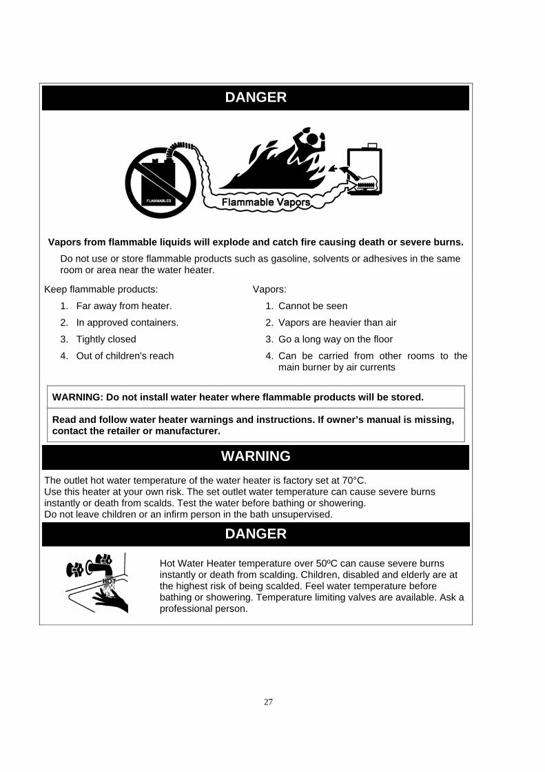
Vapors from flammable liquids will explode and catch fire causing death or severe burns.
Do not use or store flammable products such as gasoline, solvents or adhesives in the same room or area near the water heater.
Keep flammable products:
1. Far away from heater.
2. In approved containers.
3. Tightly closed
4. Out of children's reach
Vapors:
1. Cannot be seen
2. Vapors are heavier than air
3. Go a long way on the floor
4. Can be carried from other rooms to the main burner by air currents
WARNING: Do not install water heater where flammable products will be stored.
Read and follow water heater warnings and instructions. If owner’s manual is missing, contact the retailer or manufacturer.
WARNING
The outlet hot water temperature of the water heater is factory set at 70°C. Use this heater at your own risk. The set outlet water temperature can cause severe burns instantly or death from scalds. Test the water before bathing or showering. Do not leave children or an infirm person in the bath unsupervised.
DANGER
Hot Water Heater temperature over 50ºC can cause severe burns instantly or death from scalding. Children, disabled and elderly are at the highest risk of being scalded. Feel water temperature before bathing or showering. Temperature limiting valves are available. Ask a professional person.
28
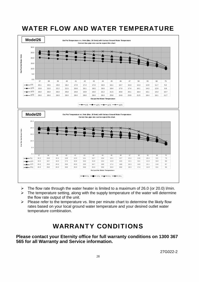
WATER FLOW AND WATER TEMPERATURE The flow rate through the water heater is limited to a maximum of 26.0 (or 20.0) l/min. The temperature setting, along with the supply temperature of the water will determine
the flow rate output of the unit. Please refer to the temperature vs. litre per minute chart to determine the likely flow
rates based on your local ground water temperature and your desired outlet water temperature combination.
WARRANTY CONDITIONS Please contact your Eternity office for full warranty conditions on 1300 367 565 for all Warranty and Service information.
27G022-2
Out Put Temperature v s. l/min (Max. 26 l/min) with Various Ground Water Temperature
Correct Gas pipe size can be expect this chart
0.0
5.0
10.0
15.0
20.0
25.0
30.0
Out put Hot Water Temperature
Ou
t P
ut
Ho
t W
ate
r l/
min
5℃ 10℃ 15℃ 20℃
5℃ 20.1 19.5 19.0 18.4 17.9 17.4 17.0 16.5 16.1 15.7 15.3 14.3 12.9 11.7 9.2
10℃ 23.9 23.0 22.2 21.5 20.8 20.1 19.5 19.0 18.4 17.9 17.4 16.1 14.3 12.9 9.9
15℃ 26.0 26.0 26.0 25.8 24.8 23.9 23.0 22.2 21.5 20.8 20.1 18.4 16.1 14.3 10.7
20℃ 26.0 26.0 26.0 26.0 26.0 26.0 26.0 26.0 25.8 24.8 23.9 21.5 18.4 16.1 11.7
37 38 39 40 41 42 43 44 45 46 47 50 55 60 75
Model26
Out Put Temperature vs. l/min (Max. 20 l/min) with Various Ground Water Temperature
Correct Gas pipe size can be expect this chart
0.0
5.0
10.0
15.0
20.0
25.0
Ou t p ut Hot Water Temperatur e
Ou
t P
ut
Ho
t W
ate
r l/
min
5℃ 10℃ 15℃ 20℃
5℃ 16.3 15.8 15.4 14.9 14.5 14.1 13.7 13.4 13.1 12.7 12.4 11.6 10.4 9.5 7.5
10℃ 19.3 18.7 18.0 17.4 16.8 16.3 15.8 15.4 14.9 14.5 14.1 13.1 11.6 10.4 8.0
15℃ 20.0 20.0 20.0 20.0 20.0 19.3 18.7 18.0 17.4 16.8 16.3 14.9 13.1 11.6 8.7
20℃ 20.0 20.0 20.0 20.0 20.0 20.0 20.0 20.0 20.0 20.0 19.3 17.4 14.9 13.1 9.5
37 38 39 40 41 42 43 44 45 46 47 50 55 60 75
Model20