Embed Size (px)
Citation preview
July 2018 AN4967 Rev 4 1/37
1
AN4967Application note
Examples of AT commands on I-CUBE-LRWAN
Introduction
I-CUBE-LRWAN is a LoRaWAN™ software expansion for STM32Cube. This expansion package consists of a set of libraries and application examples for microcontrollers of the STM32L0 Series, STM32L1 Series and STM32L4 Series acting as end devices.
The I-CUBE-LRWAN main features are:
• Easy add-on of the low-power LoRa® solution
• Extremely low CPU load
• No latency requirements
• Small STM32L0 Series memory footprint
This application note describes the set of AT commands for the B-L072Z-LRWAN1 Discovery board embedding the CMWX1ZZABZ-091 LoRa® module.
This document explains how to interface with the LoRaWAN™ to manage the LoRa® wireless link using AT commands.
For more information on the LoRa® embedded expansion software (I-CUBE-LRWAN) implementation on the STM32Lx Series, refer to the user manual STM32 LoRa™ software expansion for STM32Cube (UM2073), available at www.st.com.
www.st.com
Contents AN4967
2/37 AN4967 Rev 4
Contents
1 Acronyms . . . . . . . . . . . . . . . . . . . . . . . . . . . . . . . . . . . . . . . . . . . . . . . . . . 6
2 Reference documents . . . . . . . . . . . . . . . . . . . . . . . . . . . . . . . . . . . . . . . . 7
3 Overview . . . . . . . . . . . . . . . . . . . . . . . . . . . . . . . . . . . . . . . . . . . . . . . . . . 8
4 AT commands . . . . . . . . . . . . . . . . . . . . . . . . . . . . . . . . . . . . . . . . . . . . . . 9
4.1 General commands . . . . . . . . . . . . . . . . . . . . . . . . . . . . . . . . . . . . . . . . . .11
4.1.1 AT: attention . . . . . . . . . . . . . . . . . . . . . . . . . . . . . . . . . . . . . . . . . . . . . . 11
4.1.2 AT?: short help . . . . . . . . . . . . . . . . . . . . . . . . . . . . . . . . . . . . . . . . . . . . 12
4.1.3 ATZ: MCU reset . . . . . . . . . . . . . . . . . . . . . . . . . . . . . . . . . . . . . . . . . . . 12
4.2 Keys, IDs and EUIs management . . . . . . . . . . . . . . . . . . . . . . . . . . . . . . 13
4.2.1 AT+APPEUI: application identifier . . . . . . . . . . . . . . . . . . . . . . . . . . . . . 13
4.2.2 AT+APPKEY: application key . . . . . . . . . . . . . . . . . . . . . . . . . . . . . . . . 13
4.2.3 AT+APPSKEY: application session key . . . . . . . . . . . . . . . . . . . . . . . . . 14
4.2.4 AT+DADDR: device address . . . . . . . . . . . . . . . . . . . . . . . . . . . . . . . . . 14
4.2.5 AT+DEUI: device EUI . . . . . . . . . . . . . . . . . . . . . . . . . . . . . . . . . . . . . . 15
4.2.6 AT+NWKID: network ID . . . . . . . . . . . . . . . . . . . . . . . . . . . . . . . . . . . . . 15
4.2.7 AT+NWKSKEY: network session key . . . . . . . . . . . . . . . . . . . . . . . . . . 16
4.3 Joining and sending data on LoRa® network . . . . . . . . . . . . . . . . . . . . . . 16
4.3.1 AT+CFM: confirm mode . . . . . . . . . . . . . . . . . . . . . . . . . . . . . . . . . . . . . 16
4.3.2 AT+CFS: confirm status . . . . . . . . . . . . . . . . . . . . . . . . . . . . . . . . . . . . . 17
4.3.3 AT+JOIN: join LoRa® network . . . . . . . . . . . . . . . . . . . . . . . . . . . . . . . . 17
4.3.4 AT+NJM: LoRa® network join mode . . . . . . . . . . . . . . . . . . . . . . . . . . . 17
4.3.5 AT+NJS: LoRa® network join status . . . . . . . . . . . . . . . . . . . . . . . . . . . 18
4.3.6 AT+RECV: last received text data . . . . . . . . . . . . . . . . . . . . . . . . . . . . . 18
4.3.7 AT+RECVB: last received binary data . . . . . . . . . . . . . . . . . . . . . . . . . . 18
4.3.8 AT+SEND: send text data . . . . . . . . . . . . . . . . . . . . . . . . . . . . . . . . . . . 19
4.3.9 AT+SENB: send binary data . . . . . . . . . . . . . . . . . . . . . . . . . . . . . . . . . 19
4.4 LoRa® network management . . . . . . . . . . . . . . . . . . . . . . . . . . . . . . . . . . 20
4.4.1 AT+ADR: adaptive rate . . . . . . . . . . . . . . . . . . . . . . . . . . . . . . . . . . . . . 20
4.4.2 AT+CLASS: LoRa® class . . . . . . . . . . . . . . . . . . . . . . . . . . . . . . . . . . . . 21
4.4.3 AT+DCS: duty cycle settings . . . . . . . . . . . . . . . . . . . . . . . . . . . . . . . . . 21
4.4.4 AT+DR: data rate . . . . . . . . . . . . . . . . . . . . . . . . . . . . . . . . . . . . . . . . . . 22
AN4967 Rev 4 3/37
AN4967 Contents
3
4.4.5 AT+JN1DL: join delay on RX window 1 . . . . . . . . . . . . . . . . . . . . . . . . . 22
4.4.6 AT+JN2DL: join delay on RX window 2 . . . . . . . . . . . . . . . . . . . . . . . . . 23
4.4.7 AT+PNM: public network mode . . . . . . . . . . . . . . . . . . . . . . . . . . . . . . . 23
4.4.8 AT+RX1DL: delay of the received window 1 . . . . . . . . . . . . . . . . . . . . . 24
4.4.9 AT+RX2DL: delay of the received window 2 . . . . . . . . . . . . . . . . . . . . . 24
4.4.10 AT+RX2DR: data rate of the received window 2 . . . . . . . . . . . . . . . . . . 25
4.4.11 AT+RX2FQ: frequency of the received window 2 . . . . . . . . . . . . . . . . . 25
4.4.12 AT+TXP: transmit power . . . . . . . . . . . . . . . . . . . . . . . . . . . . . . . . . . . . 26
4.5 Information . . . . . . . . . . . . . . . . . . . . . . . . . . . . . . . . . . . . . . . . . . . . . . . . 26
4.5.1 AT+BAT: battery level . . . . . . . . . . . . . . . . . . . . . . . . . . . . . . . . . . . . . . . 26
4.5.2 AT+RSSI: RSSI on reception . . . . . . . . . . . . . . . . . . . . . . . . . . . . . . . . . 27
4.5.3 AT+SNR: signal noise ratio . . . . . . . . . . . . . . . . . . . . . . . . . . . . . . . . . . 27
4.5.4 AT+VER: version of the firmware . . . . . . . . . . . . . . . . . . . . . . . . . . . . . . 27
4.6 RF tests . . . . . . . . . . . . . . . . . . . . . . . . . . . . . . . . . . . . . . . . . . . . . . . . . . 28
4.6.1 AT+TRSSI: Start Radio Frequency RSSI Tone test . . . . . . . . . . . . . . . . 28
4.6.2 AT+TTONE: Start Radio Frequency Tone test . . . . . . . . . . . . . . . . . . . . 28
4.6.3 AT+TTLRA: Start RF Tx LoRa® test . . . . . . . . . . . . . . . . . . . . . . . . . . . 28
4.6.4 AT+TRLRA: Start RF Rx LORA test . . . . . . . . . . . . . . . . . . . . . . . . . . . 29
4.6.5 AT+TCONF: Config LoRa® RF test . . . . . . . . . . . . . . . . . . . . . . . . . . . . 29
4.6.6 AT+TOFF: Stop ongoing Radio Frequency test . . . . . . . . . . . . . . . . . . . 30
4.6.7 AT+CERTIF: Set the module in LoRaWAN™ Certification Mode . . . . . 30
5 Examples . . . . . . . . . . . . . . . . . . . . . . . . . . . . . . . . . . . . . . . . . . . . . . . . . 31
5.1 Join and send . . . . . . . . . . . . . . . . . . . . . . . . . . . . . . . . . . . . . . . . . . . . . . 31
5.2 Confirmation . . . . . . . . . . . . . . . . . . . . . . . . . . . . . . . . . . . . . . . . . . . . . . . 31
5.3 Receiving data . . . . . . . . . . . . . . . . . . . . . . . . . . . . . . . . . . . . . . . . . . . . . 33
6 Embedded software description . . . . . . . . . . . . . . . . . . . . . . . . . . . . . . 34
6.1 Firmware overview . . . . . . . . . . . . . . . . . . . . . . . . . . . . . . . . . . . . . . . . . . 34
6.2 LPUART . . . . . . . . . . . . . . . . . . . . . . . . . . . . . . . . . . . . . . . . . . . . . . . . . . 34
6.3 Compilation switches . . . . . . . . . . . . . . . . . . . . . . . . . . . . . . . . . . . . . . . . 34
6.3.1 Debug switches . . . . . . . . . . . . . . . . . . . . . . . . . . . . . . . . . . . . . . . . . . . 35
6.4 Footprint . . . . . . . . . . . . . . . . . . . . . . . . . . . . . . . . . . . . . . . . . . . . . . . . . . 35
7 Revision history . . . . . . . . . . . . . . . . . . . . . . . . . . . . . . . . . . . . . . . . . . . 36
List of tables AN4967
4/37 AN4967 Rev 4
List of tables
Table 1. List of acronyms . . . . . . . . . . . . . . . . . . . . . . . . . . . . . . . . . . . . . . . . . . . . . . . . . . . . . . . . . . 6Table 2. Link check command . . . . . . . . . . . . . . . . . . . . . . . . . . . . . . . . . . . . . . . . . . . . . . . . . . . . . 11Table 3. Short help command. . . . . . . . . . . . . . . . . . . . . . . . . . . . . . . . . . . . . . . . . . . . . . . . . . . . . . 12Table 4. MCU reset command . . . . . . . . . . . . . . . . . . . . . . . . . . . . . . . . . . . . . . . . . . . . . . . . . . . . . 12Table 5. Application identifier command. . . . . . . . . . . . . . . . . . . . . . . . . . . . . . . . . . . . . . . . . . . . . . 13Table 6. Application key command. . . . . . . . . . . . . . . . . . . . . . . . . . . . . . . . . . . . . . . . . . . . . . . . . . 13Table 7. Application session key command . . . . . . . . . . . . . . . . . . . . . . . . . . . . . . . . . . . . . . . . . . . 14Table 8. Device address command . . . . . . . . . . . . . . . . . . . . . . . . . . . . . . . . . . . . . . . . . . . . . . . . . 14Table 9. Device EUI command . . . . . . . . . . . . . . . . . . . . . . . . . . . . . . . . . . . . . . . . . . . . . . . . . . . . . 15Table 10. Network ID command . . . . . . . . . . . . . . . . . . . . . . . . . . . . . . . . . . . . . . . . . . . . . . . . . . . . . 15Table 11. Network session key command . . . . . . . . . . . . . . . . . . . . . . . . . . . . . . . . . . . . . . . . . . . . . 16Table 12. Confirm mode command . . . . . . . . . . . . . . . . . . . . . . . . . . . . . . . . . . . . . . . . . . . . . . . . . . 16Table 13. Confirm status command . . . . . . . . . . . . . . . . . . . . . . . . . . . . . . . . . . . . . . . . . . . . . . . . . . 17Table 14. Join LoRa® network command . . . . . . . . . . . . . . . . . . . . . . . . . . . . . . . . . . . . . . . . . . . . . . 17Table 15. LoRa® network join mode command . . . . . . . . . . . . . . . . . . . . . . . . . . . . . . . . . . . . . . . . . 17Table 16. LoRa® network join status command . . . . . . . . . . . . . . . . . . . . . . . . . . . . . . . . . . . . . . . . . 18Table 17. Last received text data command. . . . . . . . . . . . . . . . . . . . . . . . . . . . . . . . . . . . . . . . . . . . 18Table 18. Last received binary data command. . . . . . . . . . . . . . . . . . . . . . . . . . . . . . . . . . . . . . . . . . 19Table 19. Send text data command . . . . . . . . . . . . . . . . . . . . . . . . . . . . . . . . . . . . . . . . . . . . . . . . . . 19Table 20. Send binary data command . . . . . . . . . . . . . . . . . . . . . . . . . . . . . . . . . . . . . . . . . . . . . . . . 20Table 21. Adaptive rate command . . . . . . . . . . . . . . . . . . . . . . . . . . . . . . . . . . . . . . . . . . . . . . . . . . . 20Table 22. LoRa® class command . . . . . . . . . . . . . . . . . . . . . . . . . . . . . . . . . . . . . . . . . . . . . . . . . . . . 21Table 23. Duty cycle settings command . . . . . . . . . . . . . . . . . . . . . . . . . . . . . . . . . . . . . . . . . . . . . . . 21Table 24. Data rate command . . . . . . . . . . . . . . . . . . . . . . . . . . . . . . . . . . . . . . . . . . . . . . . . . . . . . . 22Table 25. Join delay on RX window 1 command . . . . . . . . . . . . . . . . . . . . . . . . . . . . . . . . . . . . . . . . 22Table 26. Join delay on RX window 2 command . . . . . . . . . . . . . . . . . . . . . . . . . . . . . . . . . . . . . . . . 23Table 27. Public network mode command . . . . . . . . . . . . . . . . . . . . . . . . . . . . . . . . . . . . . . . . . . . . . 23Table 28. Delay of the received window 1 command . . . . . . . . . . . . . . . . . . . . . . . . . . . . . . . . . . . . . 24Table 29. Delay of the received window 2 command . . . . . . . . . . . . . . . . . . . . . . . . . . . . . . . . . . . . . 24Table 30. Data rate of the received window 2 command . . . . . . . . . . . . . . . . . . . . . . . . . . . . . . . . . . 25Table 31. Frequency of the received window 2 command . . . . . . . . . . . . . . . . . . . . . . . . . . . . . . . . . 25Table 32. Transmit power command . . . . . . . . . . . . . . . . . . . . . . . . . . . . . . . . . . . . . . . . . . . . . . . . . 26Table 33. Battery level command . . . . . . . . . . . . . . . . . . . . . . . . . . . . . . . . . . . . . . . . . . . . . . . . . . . . 26Table 34. RSSI on reception command . . . . . . . . . . . . . . . . . . . . . . . . . . . . . . . . . . . . . . . . . . . . . . . 27Table 35. Signal noise ratio command . . . . . . . . . . . . . . . . . . . . . . . . . . . . . . . . . . . . . . . . . . . . . . . . 27Table 36. Version of the firmware command . . . . . . . . . . . . . . . . . . . . . . . . . . . . . . . . . . . . . . . . . . . 27Table 37. Start Radio Frequency RSSI Tone command . . . . . . . . . . . . . . . . . . . . . . . . . . . . . . . . . . 28Table 38. Start Radio Frequency Tone test command . . . . . . . . . . . . . . . . . . . . . . . . . . . . . . . . . . . . 28Table 39. Start RF Tx LoRa® test command . . . . . . . . . . . . . . . . . . . . . . . . . . . . . . . . . . . . . . . . . . . 28Table 40. Start RF Rx LoRa® test command . . . . . . . . . . . . . . . . . . . . . . . . . . . . . . . . . . . . . . . . . . . 29Table 41. Config LoRa® RF test command . . . . . . . . . . . . . . . . . . . . . . . . . . . . . . . . . . . . . . . . . . . . 29Table 42. Stop Radio Frequency test command . . . . . . . . . . . . . . . . . . . . . . . . . . . . . . . . . . . . . . . . 30Table 43. Set the module in LoRaWAN™ Certification Mode command . . . . . . . . . . . . . . . . . . . . . . 30Table 44. Compilation switch options . . . . . . . . . . . . . . . . . . . . . . . . . . . . . . . . . . . . . . . . . . . . . . . . . 35Table 45. AT_slave footprint . . . . . . . . . . . . . . . . . . . . . . . . . . . . . . . . . . . . . . . . . . . . . . . . . . . . . . . . 35Table 46. Document revision history . . . . . . . . . . . . . . . . . . . . . . . . . . . . . . . . . . . . . . . . . . . . . . . . . 36

AN4967 Rev 4 5/37
AN4967 List of figures
5
List of figures
Figure 1. Terminal emulation mode . . . . . . . . . . . . . . . . . . . . . . . . . . . . . . . . . . . . . . . . . . . . . . . . . . . 9Figure 2. AT master mode . . . . . . . . . . . . . . . . . . . . . . . . . . . . . . . . . . . . . . . . . . . . . . . . . . . . . . . . . . 9Figure 3. Tera Term port setup example . . . . . . . . . . . . . . . . . . . . . . . . . . . . . . . . . . . . . . . . . . . . . . 10Figure 4. Tera Term terminal setup example. . . . . . . . . . . . . . . . . . . . . . . . . . . . . . . . . . . . . . . . . . . 10
Acronyms AN4967
6/37 AN4967 Rev 4
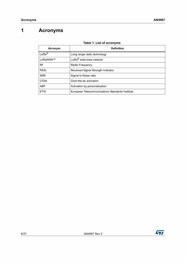
1 Acronyms
Table 1. List of acronyms
Acronym Definition
LoRa® Long range radio technology
LoRaWAN™ LoRa® wide-area network
RF Radio Frequency
RSSI Received Signal Strength Indicator
SNR Signal to Noise ratio
OTAA Over-the-air activation
ABP Activation by personalization
ETSI European Telecommunications Standards Institute
AN4967 Rev 4 7/37
AN4967 Reference documents
36
2 Reference documents
1. LoRaWAN™ Specification by LoRa Alliance™ (Version 1.0.3, March 2018, Final, Released), available at www.lora-alliance.org
2. STM32 LoRa™ software expansion for STM32Cube (UM2073), available at www.st.com
Overview AN4967
8/37 AN4967 Rev 4
3 Overview
The B-L072Z-LRWAN1 Discovery board embeds the CMWX1ZZABZ-091 LoRa® firmware.
This firmware Implements the AT_Slave module (see document 2) that supports a set of AT commands to drive the LoRaWAN™ communications and the LoRa® RF test.
It applies to microcontrollers of the STM32L0, STM32L1 and STM32L4 Series, all based on Arm®(a) cores.
The following sections contain the Interface description, the AT Commands definition, and the description of some use cases and of the embedded software.
a. Arm is a registered trademark of Arm Limited (or its subsidiaries) in the US and/or elsewhere.
AN4967 Rev 4 9/37
AN4967 AT commands
36
4 AT commands
The AT command set is a standard developed by “Hayes” to control modems. AT stands for attention.
The command set consists of a series of short text strings providing operations such as joining, data exchange and parameters setting.
In a context of LoRa® modem, the Hayes command set is a variation of the standard AT Hayes commands.
The AT commands are used to drive the LoRa® module and to send data (refer to document 1). The AT commands are sent through the UART.
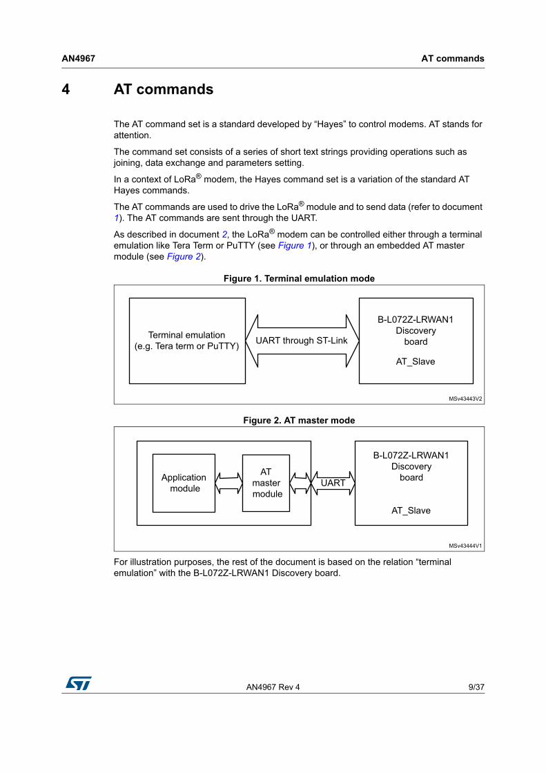
As described in document 2, the LoRa® modem can be controlled either through a terminal emulation like Tera Term or PuTTY (see Figure 1), or through an embedded AT master module (see Figure 2).
Figure 1. Terminal emulation mode
Figure 2. AT master mode
For illustration purposes, the rest of the document is based on the relation “terminal emulation” with the B-L072Z-LRWAN1 Discovery board.
AT commands AN4967
10/37 AN4967 Rev 4
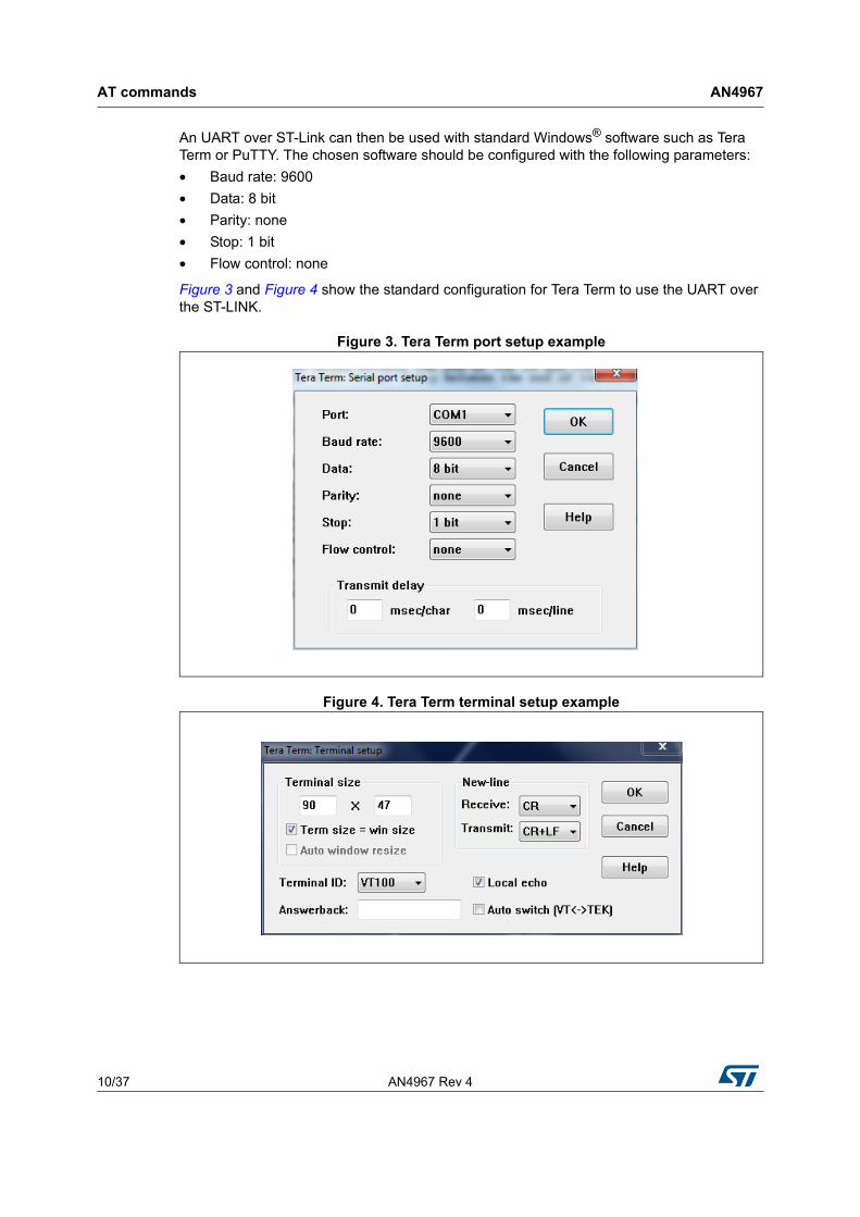
An UART over ST-Link can then be used with standard Windows® software such as Tera Term or PuTTY. The chosen software should be configured with the following parameters:
• Baud rate: 9600
• Data: 8 bit
• Parity: none
• Stop: 1 bit
• Flow control: none
Figure 3 and Figure 4 show the standard configuration for Tera Term to use the UART over the ST-LINK.
Figure 3. Tera Term port setup example
Figure 4. Tera Term terminal setup example
AN4967 Rev 4 11/37
AN4967 AT commands
36
All the AT commands have a standard format as “AT+XXX”, with XXX denoting the command. There are four available command behaviors:
• AT+XXX? provides a short help of the given command, for example AT+DEUI?
• AT+XXX is used to run a command, such as AT+JOIN
• AT+XXX=? is used to get the value of a given command, for example AT+CFS=?
• AT+XXX=<value> is used to provide a value to a command, for example AT+SEND=2:Hello
The output of the commands is provided on the UART. The output format is as below:
<value><CR><LF>
<CR><LF><Status<CR><LF>
Note: <CR> stands for “carriage return” and <LF> stands for “line feed”
The <value><CR><LF> output is returned whenever the “help AT+XXX?” or the “get AT+XXX=?” commands are run.
When no value is returned, the <value><CR><LF> output is not returned at all.
Every command (except for ATZ used for MCU reset) returns a status string, which is preceded and followed by <CR><LF> in a .”<CR><LF><Status<CR><LF>” format. The possible status are:
• OK: command run correctly without error.
• AT_ERROR: generic error
• AT_PARAM_ERROR: a parameter of the command is wrong
• AT_BUSY_ERROR: the LoRa® network is busy, so the command has not been completed
• AT_TEST_PARAM_OVERFLOW: the parameter is too long
• AT_NO_NETWORK_JOINED: the LoRa® network has not been joined yet
• AT_RX_ERROR: error detection during the reception of the command
More details on each command description and examples are described in the next part of this section. Note that each command preceded by # is the one provided by the host to the module. Then the return of the module is printed.
4.1 General commands
This section describes the commands related to “attention” help list, link control and CPU AT_Slave reset.
4.1.1 AT: attention
This command is used to check that the link is working properly (refer to Table 2 for details).
Table 2. Link check command
CommandInput
parameterReturn value Return code
AT - - OK
AT commands AN4967
12/37 AN4967 Rev 4
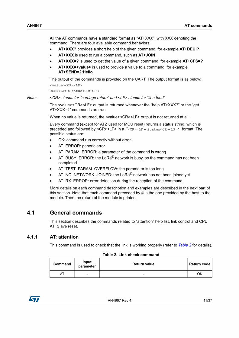
4.1.2 AT?: short help
This command provides short help for all the supported commands (refer to Table 3 for details).
4.1.3 ATZ: MCU reset
This command is used to trig a CPU reset of the B-L072Z-LRWAN1 Discovery board (refer to Table 4 for details).
Table 3. Short help command
CommandInput
parameterReturn value Return code
AT? -
AT+<CMD>?: help on <CMD
AT+<CMD>: run <CMD>
AT+<CMD>=<value>: set the value
AT+<CMD>=?: get the value
<followed by the help of all commands>
OK
Table 4. MCU reset command
CommandInput
parameterReturn value Return code
ATZ? - ATZ: triggers a reset of the MCU OK
ATZ - No return value and return code. The MCU is reset. Void
AN4967 Rev 4 13/37
AN4967 AT commands
36
4.2 Keys, IDs and EUIs management
This section gives description of the commands related to the activation of the end device.
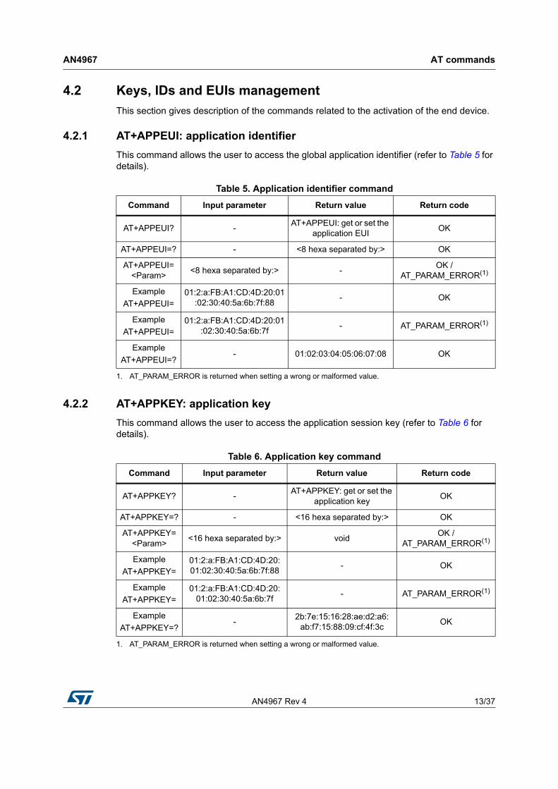
4.2.1 AT+APPEUI: application identifier
This command allows the user to access the global application identifier (refer to Table 5 for details).
4.2.2 AT+APPKEY: application key
This command allows the user to access the application session key (refer to Table 6 for details).
Table 5. Application identifier command
Command Input parameter Return value Return code
AT+APPEUI? -AT+APPEUI: get or set the
application EUIOK
AT+APPEUI=? - <8 hexa separated by:> OK
AT+APPEUI=<Param>
<8 hexa separated by:> -OK /
AT_PARAM_ERROR(1)
1. AT_PARAM_ERROR is returned when setting a wrong or malformed value.
Example
AT+APPEUI=01:2:a:FB:A1:CD:4D:20:01
:02:30:40:5a:6b:7f:88- OK
Example
AT+APPEUI=01:2:a:FB:A1:CD:4D:20:01
:02:30:40:5a:6b:7f- AT_PARAM_ERROR(1)
Example
AT+APPEUI=?- 01:02:03:04:05:06:07:08 OK
Table 6. Application key command
Command Input parameter Return value Return code
AT+APPKEY? -AT+APPKEY: get or set the
application keyOK
AT+APPKEY=? - <16 hexa separated by:> OK
AT+APPKEY=<Param>
<16 hexa separated by:> voidOK /
AT_PARAM_ERROR(1)
1. AT_PARAM_ERROR is returned when setting a wrong or malformed value.
Example
AT+APPKEY=01:2:a:FB:A1:CD:4D:20:01:02:30:40:5a:6b:7f:88
- OK
Example
AT+APPKEY=01:2:a:FB:A1:CD:4D:20:
01:02:30:40:5a:6b:7f- AT_PARAM_ERROR(1)
Example
AT+APPKEY=?-
2b:7e:15:16:28:ae:d2:a6:ab:f7:15:88:09:cf:4f:3c
OK
AT commands AN4967
14/37 AN4967 Rev 4
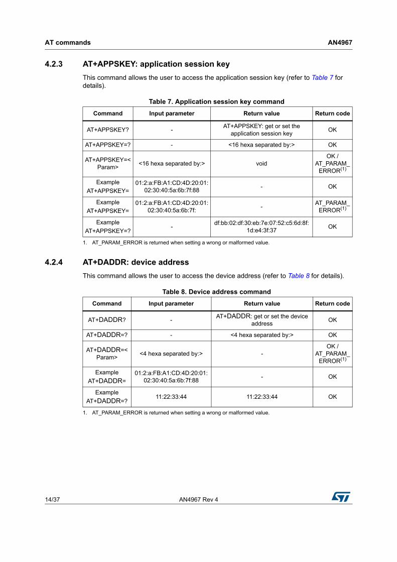
4.2.3 AT+APPSKEY: application session key
This command allows the user to access the application session key (refer to Table 7 for details).
4.2.4 AT+DADDR: device address
This command allows the user to access the device address (refer to Table 8 for details).
Table 7. Application session key command
Command Input parameter Return value Return code
AT+APPSKEY? -AT+APPSKEY: get or set the
application session keyOK
AT+APPSKEY=? - <16 hexa separated by:> OK
AT+APPSKEY=<Param>
<16 hexa separated by:> voidOK /
AT_PARAM_ERROR(1)
1. AT_PARAM_ERROR is returned when setting a wrong or malformed value.
Example
AT+APPSKEY=01:2:a:FB:A1:CD:4D:20:01:
02:30:40:5a:6b:7f:88- OK
Example
AT+APPSKEY=01:2:a:FB:A1:CD:4D:20:01:
02:30:40:5a:6b:7f:-
AT_PARAM_ERROR(1)
Example
AT+APPSKEY=?-
df:bb:02:df:30:eb:7e:07:52:c5:6d:8f:1d:e4:3f:37
OK
Table 8. Device address command
Command Input parameter Return value Return code
AT+DADDR? -AT+DADDR: get or set the device
addressOK
AT+DADDR=? - <4 hexa separated by:> OK
AT+DADDR=<Param>
<4 hexa separated by:> -OK /
AT_PARAM_ERROR(1)
1. AT_PARAM_ERROR is returned when setting a wrong or malformed value.
Example
AT+DADDR=01:2:a:FB:A1:CD:4D:20:01:
02:30:40:5a:6b:7f:88- OK
Example
AT+DADDR=?11:22:33:44 11:22:33:44 OK
AN4967 Rev 4 15/37
AN4967 AT commands
36
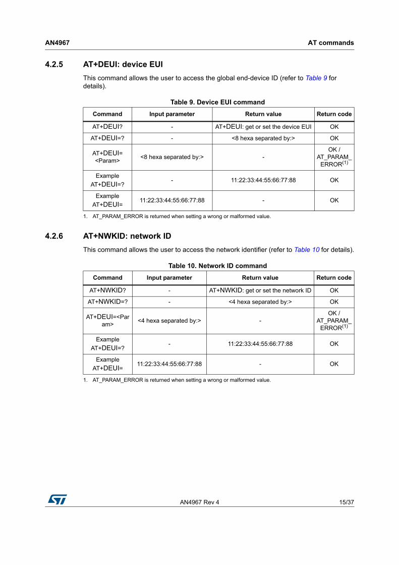
4.2.5 AT+DEUI: device EUI
This command allows the user to access the global end-device ID (refer to Table 9 for details).
4.2.6 AT+NWKID: network ID
This command allows the user to access the network identifier (refer to Table 10 for details).
Table 9. Device EUI command
Command Input parameter Return value Return code
AT+DEUI? - AT+DEUI: get or set the device EUI OK
AT+DEUI=? - <8 hexa separated by:> OK
AT+DEUI=<Param>
<8 hexa separated by:> -OK /
AT_PARAM_ERROR(1)
1. AT_PARAM_ERROR is returned when setting a wrong or malformed value.
Example
AT+DEUI=?- 11:22:33:44:55:66:77:88 OK
Example
AT+DEUI=11:22:33:44:55:66:77:88 - OK
Table 10. Network ID command
Command Input parameter Return value Return code
AT+NWKID? - AT+NWKID: get or set the network ID OK
AT+NWKID=? - <4 hexa separated by:> OK
AT+DEUI=<Param>
<4 hexa separated by:> -OK /
AT_PARAM_ERROR(1)
1. AT_PARAM_ERROR is returned when setting a wrong or malformed value.
Example
AT+DEUI=?- 11:22:33:44:55:66:77:88 OK
Example
AT+DEUI=11:22:33:44:55:66:77:88 - OK
AT commands AN4967
16/37 AN4967 Rev 4
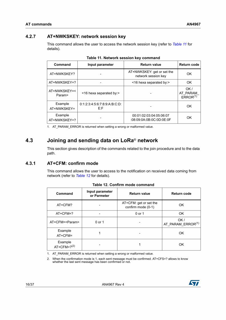
4.2.7 AT+NWKSKEY: network session key
This command allows the user to access the network session key (refer to Table 11 for details).
4.3 Joining and sending data on LoRa® network
This section gives description of the commands related to the join procedure and to the data path.
4.3.1 AT+CFM: confirm mode
This command allows the user to access to the notification on received data coming from network (refer to Table 12 for details).
Table 11. Network session key command
Command Input parameter Return value Return code
AT+NWKSKEY? -AT+NWKSKEY: get or set the
network session keyOK
AT+NWKSKEY=? - <16 hexa separated by:> OK
AT+NWKSKEY=<Param>
<16 hexa separated by:> -OK /
AT_PARAM_ERROR(1)
1. AT_PARAM_ERROR is returned when setting a wrong or malformed value.
Example
AT+NWKSKEY=0:1:2:3:4:5:6:7:8:9:A:B:C:D:
E:F- OK
Example
AT+NWKSKEY=?-
00:01:02:03:04:05:06:07:08:09:0A:0B:0C:0D:0E:0F
OK
Table 12. Confirm mode command
CommandInput parameter
or ParmeterReturn value Return code
AT+CFM? -AT+CFM: get or set the
confirm mode (0-1)OK
AT+CFM=? - 0 or 1 OK
AT+CFM=<Param> 0 or 1 -OK /
AT_PARAM_ERROR(1)
1. AT_PARAM_ERROR is returned when setting a wrong or malformed value.
Example
AT+CFM=1 - OK
Example
AT+CFM=?(2)
2. When the confirmation mode is 1, each sent message must be confirmed. AT+CFS=? allows to know whether the last sent message has been confirmed or not.
- 1 OK
AN4967 Rev 4 17/37
AN4967 AT commands
36
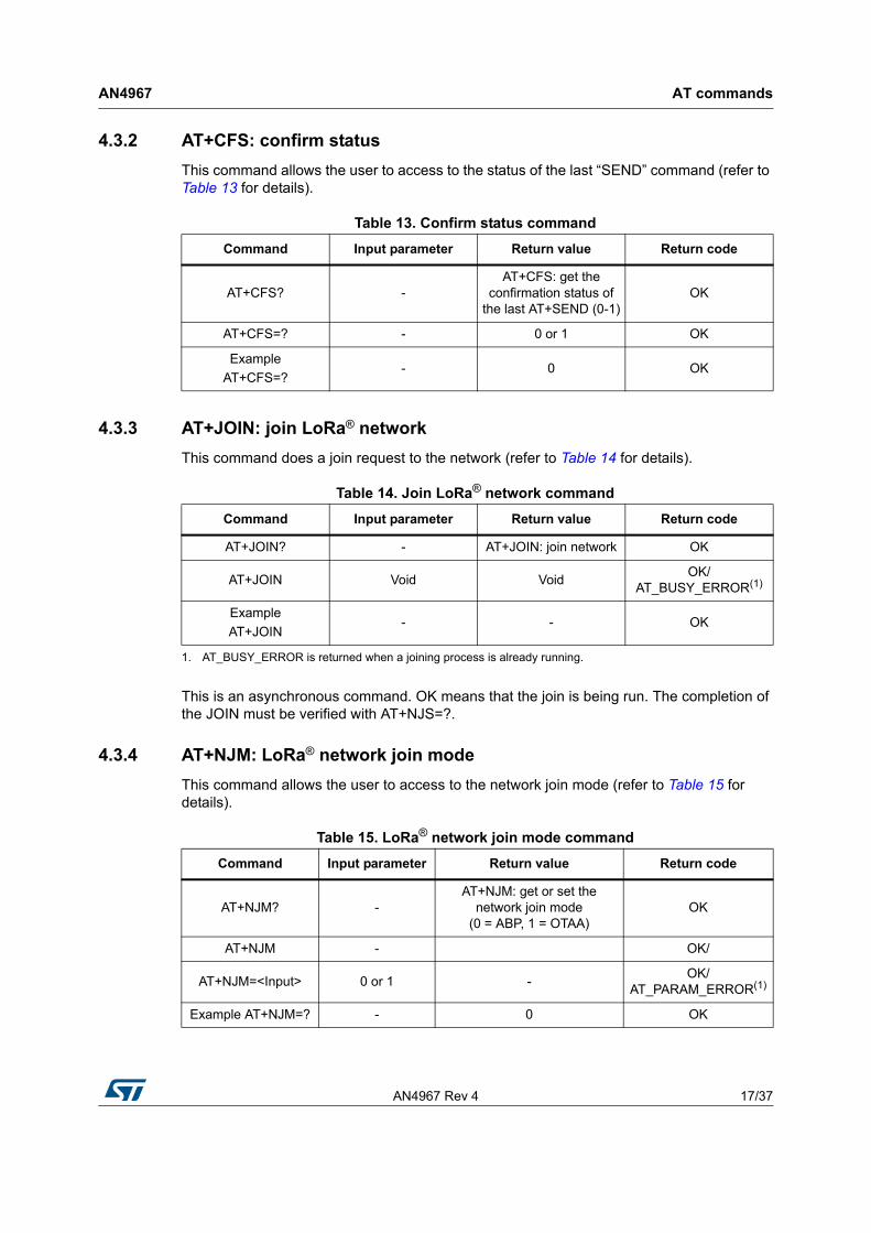
4.3.2 AT+CFS: confirm status
This command allows the user to access to the status of the last “SEND” command (refer to Table 13 for details).
4.3.3 AT+JOIN: join LoRa® network
This command does a join request to the network (refer to Table 14 for details).
This is an asynchronous command. OK means that the join is being run. The completion of the JOIN must be verified with AT+NJS=?.
4.3.4 AT+NJM: LoRa® network join mode
This command allows the user to access to the network join mode (refer to Table 15 for details).
Table 13. Confirm status command
Command Input parameter Return value Return code
AT+CFS? -AT+CFS: get the
confirmation status of the last AT+SEND (0-1)
OK
AT+CFS=? - 0 or 1 OK
Example
AT+CFS=?- 0 OK
Table 14. Join LoRa® network command
Command Input parameter Return value Return code
AT+JOIN? - AT+JOIN: join network OK
AT+JOIN Void VoidOK/
AT_BUSY_ERROR(1)
1. AT_BUSY_ERROR is returned when a joining process is already running.
Example
AT+JOIN- - OK
Table 15. LoRa® network join mode command
Command Input parameter Return value Return code
AT+NJM? -AT+NJM: get or set the
network join mode(0 = ABP, 1 = OTAA)
OK
AT+NJM - OK/
AT+NJM=<Input> 0 or 1 -OK/
AT_PARAM_ERROR(1)
Example AT+NJM=? - 0 OK
AT commands AN4967
18/37 AN4967 Rev 4
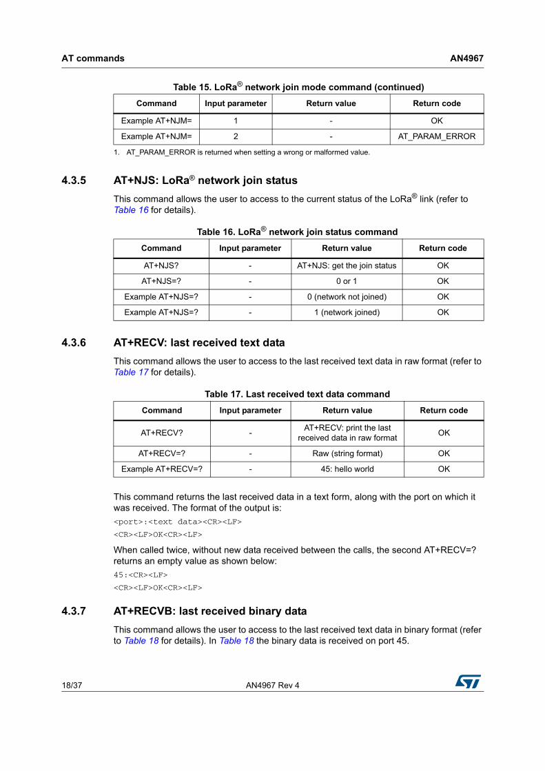
4.3.5 AT+NJS: LoRa® network join status
This command allows the user to access to the current status of the LoRa® link (refer to Table 16 for details).
4.3.6 AT+RECV: last received text data
This command allows the user to access to the last received text data in raw format (refer to Table 17 for details).
This command returns the last received data in a text form, along with the port on which it was received. The format of the output is:
<port>:<text data><CR><LF>
<CR><LF>OK<CR><LF>
When called twice, without new data received between the calls, the second AT+RECV=? returns an empty value as shown below:
45:<CR><LF>
<CR><LF>OK<CR><LF>
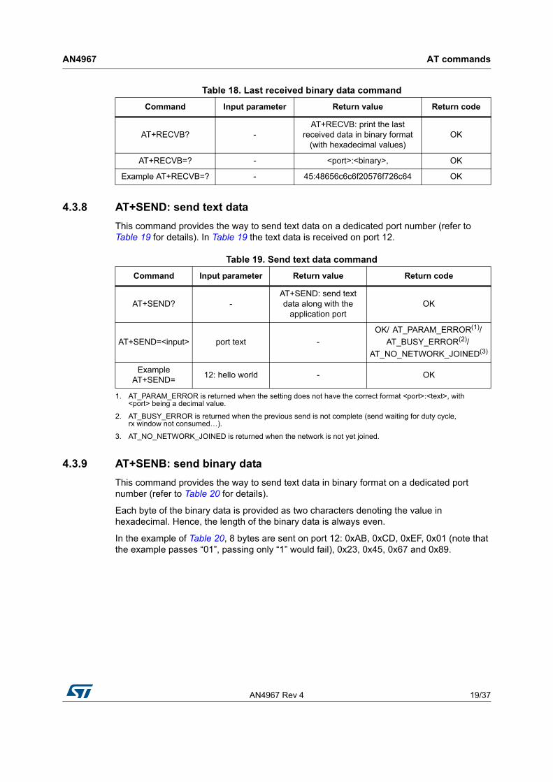
4.3.7 AT+RECVB: last received binary data
This command allows the user to access to the last received text data in binary format (refer to Table 18 for details). In Table 18 the binary data is received on port 45.
Example AT+NJM= 1 - OK
Example AT+NJM= 2 - AT_PARAM_ERROR
1. AT_PARAM_ERROR is returned when setting a wrong or malformed value.
Table 15. LoRa® network join mode command (continued)
Command Input parameter Return value Return code
Table 16. LoRa® network join status command
Command Input parameter Return value Return code
AT+NJS? - AT+NJS: get the join status OK
AT+NJS=? - 0 or 1 OK
Example AT+NJS=? - 0 (network not joined) OK
Example AT+NJS=? - 1 (network joined) OK
Table 17. Last received text data command
Command Input parameter Return value Return code
AT+RECV? -AT+RECV: print the last
received data in raw formatOK
AT+RECV=? - Raw (string format) OK
Example AT+RECV=? - 45: hello world OK
AN4967 Rev 4 19/37
AN4967 AT commands
36
4.3.8 AT+SEND: send text data
This command provides the way to send text data on a dedicated port number (refer to Table 19 for details). In Table 19 the text data is received on port 12.
4.3.9 AT+SENB: send binary data
This command provides the way to send text data in binary format on a dedicated port number (refer to Table 20 for details).
Each byte of the binary data is provided as two characters denoting the value in hexadecimal. Hence, the length of the binary data is always even.
In the example of Table 20, 8 bytes are sent on port 12: 0xAB, 0xCD, 0xEF, 0x01 (note that the example passes “01”, passing only “1” would fail), 0x23, 0x45, 0x67 and 0x89.
Table 18. Last received binary data command
Command Input parameter Return value Return code
AT+RECVB? -AT+RECVB: print the last
received data in binary format (with hexadecimal values)
OK
AT+RECVB=? - <port>:<binary>, OK
Example AT+RECVB=? - 45:48656c6c6f20576f726c64 OK
Table 19. Send text data command
Command Input parameter Return value Return code
AT+SEND? -AT+SEND: send text data along with the
application portOK
AT+SEND=<input> port text -
OK/ AT_PARAM_ERROR(1)/
AT_BUSY_ERROR(2)/
AT_NO_NETWORK_JOINED(3)
1. AT_PARAM_ERROR is returned when the setting does not have the correct format <port>:<text>, with <port> being a decimal value.
2. AT_BUSY_ERROR is returned when the previous send is not complete (send waiting for duty cycle, rx window not consumed…).
3. AT_NO_NETWORK_JOINED is returned when the network is not yet joined.
Example AT+SEND=
12: hello world - OK
AT commands AN4967
20/37 AN4967 Rev 4
4.4 LoRa® network management
This section provides a set of commands for network management.
4.4.1 AT+ADR: adaptive rate
This command allows the user to access to the adaptive data rate (refer to Table 21 for details). The default value of the ADR is 1 (enabled).
Table 20. Send binary data command
Command Input parameter Return value Return code
AT+SENDB? -
AT+SENDB: send hexadecimal data
along with the application port
OK
AT+SENDB=<input> <port>:<binary>, -
OK/ AT_PARAM_ERROR(1)/
AT_BUSY_ERROR(2)/
AT_NO_NETWORK_JOINED(3)
1. AT_PARAM_ERROR is returned when the setting has not the correct format <port>:<binary>, with <port> being a decimal value, and <binary> following hexadecimal format using two characters as described above.
2. AT_BUSY_ERROR is returned when the previous send is not complete (send waiting for duty cycle, rx window not consumed…).
3. AT_NO_NETWORK_JOINED is returned when the network is not joined yet.
Example AT+SENDB=
12:abcdef0123456789 - OK
Example AT+SENDB=
abcdef0123456789 - AT_PARAM_ERROR
Table 21. Adaptive rate command
Command Input parameter Return value Return code
AT+ADR? -AT+ADR: get or set the
adaptive data rate setting (0 = off, 1 = on)
OK
AT+ADR=? - 0 or 1 OK
AT+ADR=<Input> 0 or 1 -OK/
AT_PARAM_ERROR(1)
1. AT_PARAM_ERROR is returned when setting a wrong or malformed value.
Example AT+ADR= 0 - OK
Example AT+ADR=? - 0 OK
AN4967 Rev 4 21/37
AN4967 AT commands
36
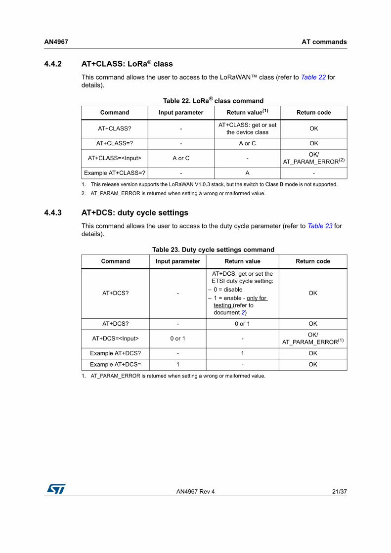
4.4.2 AT+CLASS: LoRa® class
This command allows the user to access to the LoRaWAN™ class (refer to Table 22 for details).
4.4.3 AT+DCS: duty cycle settings
This command allows the user to access to the duty cycle parameter (refer to Table 23 for details).
Table 22. LoRa® class command
Command Input parameter Return value(1)
1. This release version supports the LoRaWAN V1.0.3 stack, but the switch to Class B mode is not supported.
Return code
AT+CLASS? -AT+CLASS: get or set
the device classOK
AT+CLASS=? - A or C OK
AT+CLASS=<Input> A or C -OK/
AT_PARAM_ERROR(2)
2. AT_PARAM_ERROR is returned when setting a wrong or malformed value.
Example AT+CLASS=? - A -
Table 23. Duty cycle settings command
Command Input parameter Return value Return code
AT+DCS? -
AT+DCS: get or set the ETSI duty cycle setting:
– 0 = disable
– 1 = enable - only for testing (refer to document 2)
OK
AT+DCS? - 0 or 1 OK
AT+DCS=<Input> 0 or 1 -OK/
AT_PARAM_ERROR(1)
Example AT+DCS? - 1 OK
Example AT+DCS= 1 - OK
1. AT_PARAM_ERROR is returned when setting a wrong or malformed value.
AT commands AN4967
22/37 AN4967 Rev 4
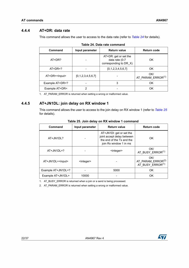
4.4.4 AT+DR: data rate
This command allows the user to access to the data rate (refer to Table 24 for details).
4.4.5 AT+JN1DL: join delay on RX window 1
This command allows the user to access to the join delay on RX window 1 (refer to Table 25 for details).
Table 24. Data rate command
Command Input parameter Return value Return code
AT+DR? -AT+DR: get or set the
data rate (0-7 corresponding to DR_X)
OK
AT+DR=? - [0,1,2,3,4,5,6,7] OK
AT+DR=<Input> [0,1,2,3,4,5,6,7] -OK/
AT_PARAM_ERROR(1)
Example AT+DR=? - 3 OK
Example AT+DR= 2 - OK
1. AT_PARAM_ERROR is returned when setting a wrong or malformed value.
Table 25. Join delay on RX window 1 command
Command Input parameter Return value Return code
AT+JN1DL? -
AT+JN1Dl: get or set the joint accept delay between the end of the Tx and the join Rx window 1 in ms
OK
AT+JN1DL=? - <integer>OK/
AT_BUSY_ERROR(1)
1. AT_BUSY_ERROR is returned when a join or a send is being processed.
AT+JN1DL=<input> <integer> -OK/
AT_PARAM_ERROR(2)
AT_BUSY_ERROR(1)
2. AT_PARAM_ERROR is returned when setting a wrong or malformed value.
Example AT+JN1DL=? - 5000 OK
Example AT+JN1DL= 10000 - OK
AN4967 Rev 4 23/37
AN4967 AT commands
36
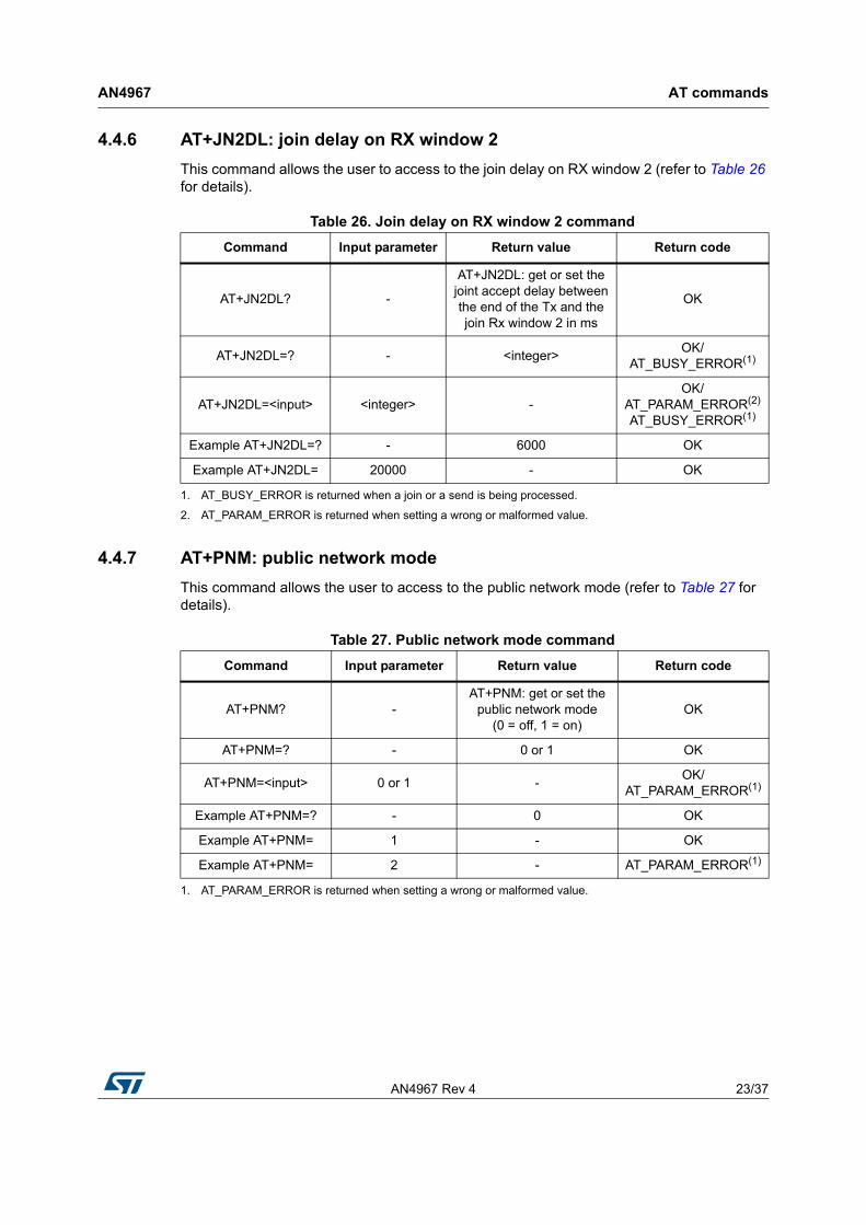
4.4.6 AT+JN2DL: join delay on RX window 2
This command allows the user to access to the join delay on RX window 2 (refer to Table 26 for details).
4.4.7 AT+PNM: public network mode
This command allows the user to access to the public network mode (refer to Table 27 for details).
Table 26. Join delay on RX window 2 command
Command Input parameter Return value Return code
AT+JN2DL? -
AT+JN2DL: get or set the joint accept delay between the end of the Tx and the join Rx window 2 in ms
OK
AT+JN2DL=? - <integer>OK/
AT_BUSY_ERROR(1)
1. AT_BUSY_ERROR is returned when a join or a send is being processed.
AT+JN2DL=<input> <integer> -OK/
AT_PARAM_ERROR(2)
AT_BUSY_ERROR(1)
2. AT_PARAM_ERROR is returned when setting a wrong or malformed value.
Example AT+JN2DL=? - 6000 OK
Example AT+JN2DL= 20000 - OK
Table 27. Public network mode command
Command Input parameter Return value Return code
AT+PNM? -AT+PNM: get or set the
public network mode(0 = off, 1 = on)
OK
AT+PNM=? - 0 or 1 OK
AT+PNM=<input> 0 or 1 -OK/
AT_PARAM_ERROR(1)
Example AT+PNM=? - 0 OK
Example AT+PNM= 1 - OK
Example AT+PNM= 2 - AT_PARAM_ERROR(1)
1. AT_PARAM_ERROR is returned when setting a wrong or malformed value.
AT commands AN4967
24/37 AN4967 Rev 4
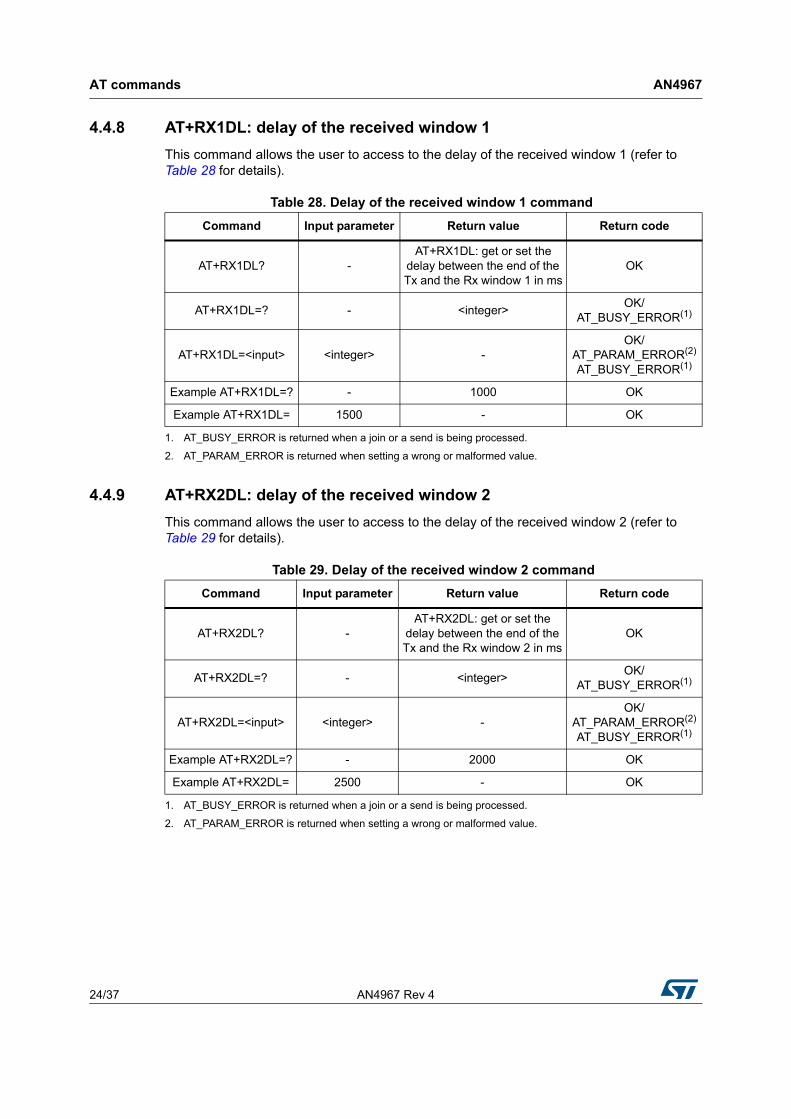
4.4.8 AT+RX1DL: delay of the received window 1
This command allows the user to access to the delay of the received window 1 (refer to Table 28 for details).
4.4.9 AT+RX2DL: delay of the received window 2
This command allows the user to access to the delay of the received window 2 (refer to Table 29 for details).
Table 28. Delay of the received window 1 command
Command Input parameter Return value Return code
AT+RX1DL? -AT+RX1DL: get or set the
delay between the end of the Tx and the Rx window 1 in ms
OK
AT+RX1DL=? - <integer>OK/
AT_BUSY_ERROR(1)
1. AT_BUSY_ERROR is returned when a join or a send is being processed.
AT+RX1DL=<input> <integer> -OK/
AT_PARAM_ERROR(2)
AT_BUSY_ERROR(1)
2. AT_PARAM_ERROR is returned when setting a wrong or malformed value.
Example AT+RX1DL=? - 1000 OK
Example AT+RX1DL= 1500 - OK
Table 29. Delay of the received window 2 command
Command Input parameter Return value Return code
AT+RX2DL? -AT+RX2DL: get or set the
delay between the end of the Tx and the Rx window 2 in ms
OK
AT+RX2DL=? - <integer>OK/
AT_BUSY_ERROR(1)
AT+RX2DL=<input> <integer> -OK/
AT_PARAM_ERROR(2)
AT_BUSY_ERROR(1)
Example AT+RX2DL=? - 2000 OK
Example AT+RX2DL= 2500 - OK
1. AT_BUSY_ERROR is returned when a join or a send is being processed.
2. AT_PARAM_ERROR is returned when setting a wrong or malformed value.
AN4967 Rev 4 25/37
AN4967 AT commands
36
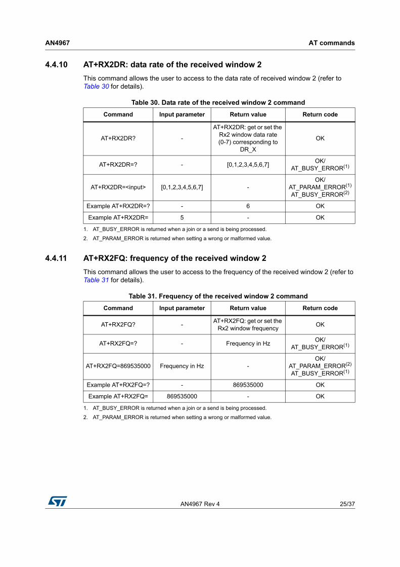
4.4.10 AT+RX2DR: data rate of the received window 2
This command allows the user to access to the data rate of received window 2 (refer to Table 30 for details).
4.4.11 AT+RX2FQ: frequency of the received window 2
This command allows the user to access to the frequency of the received window 2 (refer to Table 31 for details).
Table 30. Data rate of the received window 2 command
Command Input parameter Return value Return code
AT+RX2DR? -
AT+RX2DR: get or set the Rx2 window data rate(0-7) corresponding to
DR_X
OK
AT+RX2DR=? - [0,1,2,3,4,5,6,7]OK/
AT_BUSY_ERROR(1)
AT+RX2DR=<input> [0,1,2,3,4,5,6,7] -OK/
AT_PARAM_ERROR(1)
AT_BUSY_ERROR(2)
Example AT+RX2DR=? - 6 OK
Example AT+RX2DR= 5 - OK
1. AT_BUSY_ERROR is returned when a join or a send is being processed.
2. AT_PARAM_ERROR is returned when setting a wrong or malformed value.
Table 31. Frequency of the received window 2 command
Command Input parameter Return value Return code
AT+RX2FQ? -AT+RX2FQ: get or set the
Rx2 window frequencyOK
AT+RX2FQ=? - Frequency in HzOK/
AT_BUSY_ERROR(1)
AT+RX2FQ=869535000 Frequency in Hz -OK/
AT_PARAM_ERROR(2)
AT_BUSY_ERROR(1)
Example AT+RX2FQ=? - 869535000 OK
Example AT+RX2FQ= 869535000 - OK
1. AT_BUSY_ERROR is returned when a join or a send is being processed.
2. AT_PARAM_ERROR is returned when setting a wrong or malformed value.
AT commands AN4967
26/37 AN4967 Rev 4
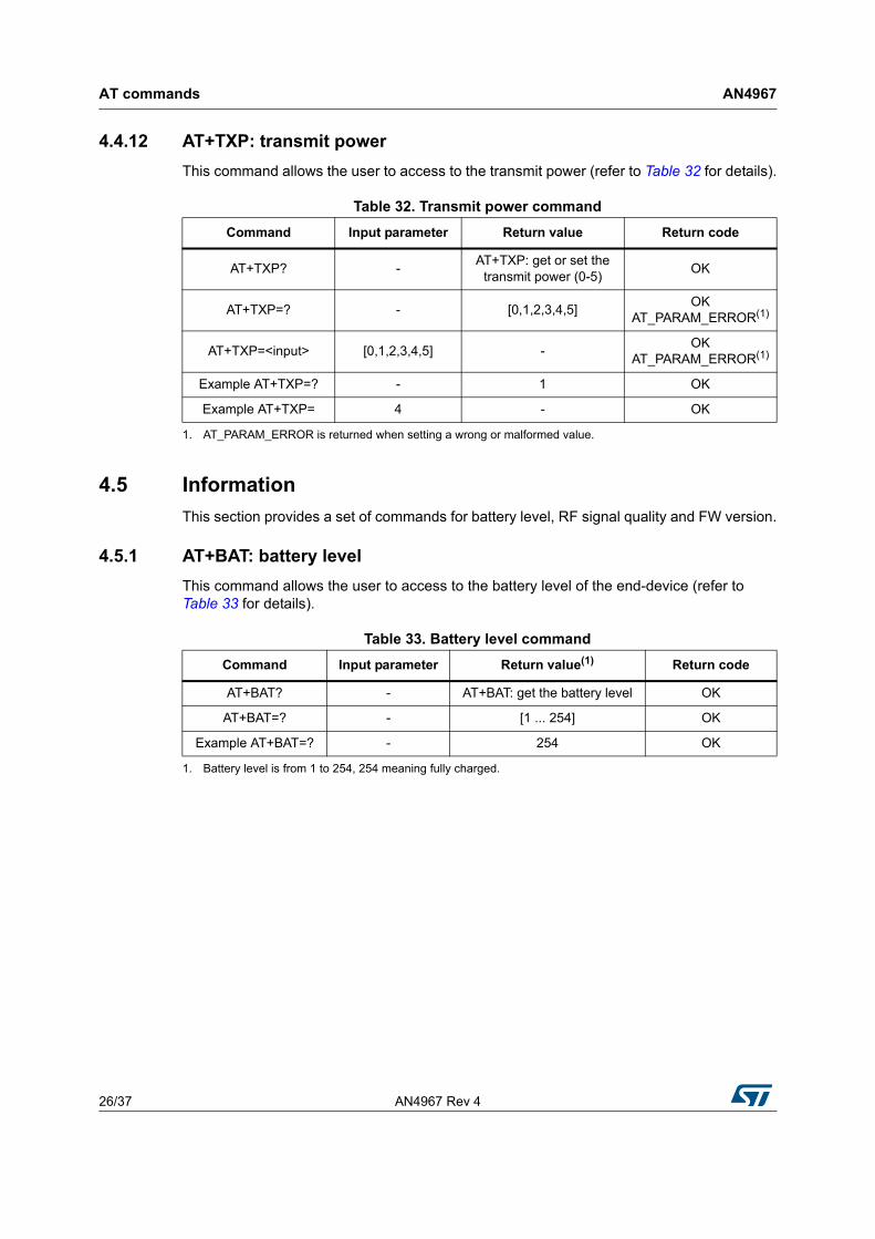
4.4.12 AT+TXP: transmit power
This command allows the user to access to the transmit power (refer to Table 32 for details).
4.5 Information
This section provides a set of commands for battery level, RF signal quality and FW version.
4.5.1 AT+BAT: battery level
This command allows the user to access to the battery level of the end-device (refer to Table 33 for details).
Table 32. Transmit power command
Command Input parameter Return value Return code
AT+TXP? -AT+TXP: get or set the
transmit power (0-5)OK
AT+TXP=? - [0,1,2,3,4,5]OK
AT_PARAM_ERROR(1)
AT+TXP=<input> [0,1,2,3,4,5] -OK
AT_PARAM_ERROR(1)
Example AT+TXP=? - 1 OK
Example AT+TXP= 4 - OK
1. AT_PARAM_ERROR is returned when setting a wrong or malformed value.
Table 33. Battery level command
Command Input parameter Return value(1)
1. Battery level is from 1 to 254, 254 meaning fully charged.
Return code
AT+BAT? - AT+BAT: get the battery level OK
AT+BAT=? - [1 ... 254] OK
Example AT+BAT=? - 254 OK
AN4967 Rev 4 27/37
AN4967 AT commands
36
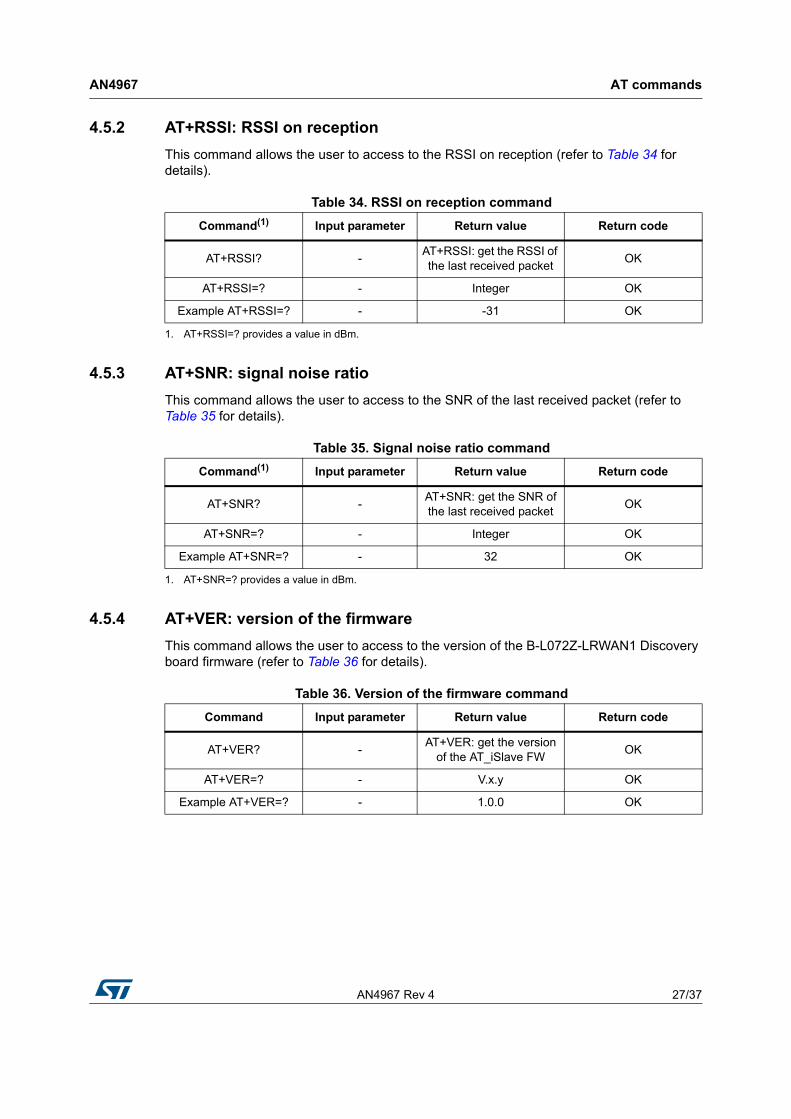
4.5.2 AT+RSSI: RSSI on reception
This command allows the user to access to the RSSI on reception (refer to Table 34 for details).
4.5.3 AT+SNR: signal noise ratio
This command allows the user to access to the SNR of the last received packet (refer to Table 35 for details).
4.5.4 AT+VER: version of the firmware
This command allows the user to access to the version of the B-L072Z-LRWAN1 Discovery board firmware (refer to Table 36 for details).
Table 34. RSSI on reception command
Command(1) Input parameter Return value Return code
AT+RSSI? -AT+RSSI: get the RSSI of the last received packet
OK
AT+RSSI=? - Integer OK
Example AT+RSSI=? - -31 OK
1. AT+RSSI=? provides a value in dBm.
Table 35. Signal noise ratio command
Command(1) Input parameter Return value Return code
AT+SNR? -AT+SNR: get the SNR of the last received packet
OK
AT+SNR=? - Integer OK
Example AT+SNR=? - 32 OK
1. AT+SNR=? provides a value in dBm.
Table 36. Version of the firmware command
Command Input parameter Return value Return code
AT+VER? -AT+VER: get the version
of the AT_iSlave FWOK
AT+VER=? - V.x.y OK
Example AT+VER=? - 1.0.0 OK
AT commands AN4967
28/37 AN4967 Rev 4
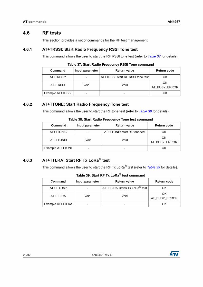
4.6 RF tests
This section provides a set of commands for the RF test management.
4.6.1 AT+TRSSI: Start Radio Frequency RSSI Tone test
This command allows the user to start the RF RSSI tone test (refer to Table 37 for details).
4.6.2 AT+TTONE: Start Radio Frequency Tone test
This command allows the user to start the RF tone test (refer to Table 38 for details).
4.6.3 AT+TTLRA: Start RF Tx LoRa® test
This command allows the user to start the RF Tx LoRa® test (refer to Table 39 for details).
Table 37. Start Radio Frequency RSSI Tone command
Command Input parameter Return value Return code
AT+TRSSI? - AT+TRSSI: start RF RSSI tone test OK
AT+TRSSI Void VoidOK
AT_BUSY_ERROR
Example AT+TRSSI - - OK
Table 38. Start Radio Frequency Tone test command
Command Input parameter Return value Return code
AT+TTONE? - AT+TTONE: start RF tone test OK
AT+TTONEI Void VoidOK
AT_BUSY_ERROR
Example AT+TTONE - - OK
Table 39. Start RF Tx LoRa® test command
Command Input parameter Return value Return code
AT+TTLRA? - AT+TTLRA: starts Tx LoRa® test OK
AT+TTLRA Void VoidOK
AT_BUSY_ERROR
Example AT+TTLRA - - OK
AN4967 Rev 4 29/37
AN4967 AT commands
36
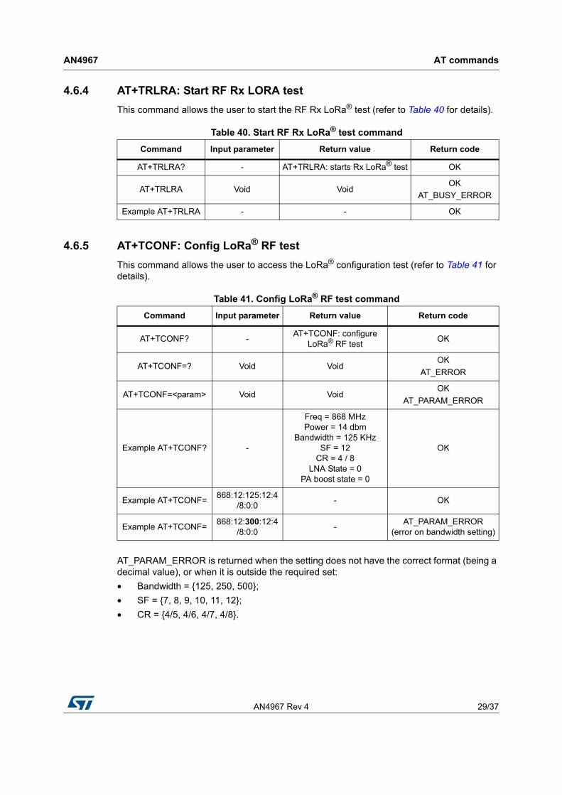
4.6.4 AT+TRLRA: Start RF Rx LORA test
This command allows the user to start the RF Rx LoRa® test (refer to Table 40 for details).
4.6.5 AT+TCONF: Config LoRa® RF test
This command allows the user to access the LoRa® configuration test (refer to Table 41 for details).
AT_PARAM_ERROR is returned when the setting does not have the correct format (being a decimal value), or when it is outside the required set:
• Bandwidth = {125, 250, 500};
• SF = {7, 8, 9, 10, 11, 12};
• CR = {4/5, 4/6, 4/7, 4/8}.
Table 40. Start RF Rx LoRa® test command
Command Input parameter Return value Return code
AT+TRLRA? - AT+TRLRA: starts Rx LoRa® test OK
AT+TRLRA Void VoidOK
AT_BUSY_ERROR
Example AT+TRLRA - - OK
Table 41. Config LoRa® RF test command
Command Input parameter Return value Return code
AT+TCONF? -AT+TCONF: configure
LoRa® RF testOK
AT+TCONF=? Void VoidOK
AT_ERROR
AT+TCONF=<param> Void VoidOK
AT_PARAM_ERROR
Example AT+TCONF? -
Freq = 868 MHzPower = 14 dbm
Bandwidth = 125 KHzSF = 12
CR = 4 / 8LNA State = 0
PA boost state = 0
OK
Example AT+TCONF=868:12:125:12:4
/8:0:0- OK
Example AT+TCONF=868:12:300:12:4
/8:0:0-
AT_PARAM_ERROR(error on bandwidth setting)
AT commands AN4967
30/37 AN4967 Rev 4
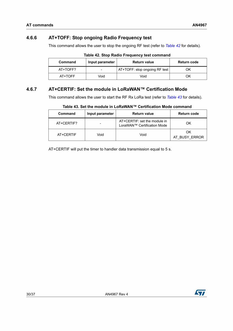
4.6.6 AT+TOFF: Stop ongoing Radio Frequency test
This command allows the user to stop the ongoing RF test (refer to Table 42 for details).
4.6.7 AT+CERTIF: Set the module in LoRaWAN™ Certification Mode
This command allows the user to start the RF Rx LoRa test (refer to Table 43 for details).
AT+CERTIF will put the timer to handler data transmission equal to 5 s.
Table 42. Stop Radio Frequency test command
Command Input parameter Return value Return code
AT+TOFF? - AT+TOFF: stop ongoing RF test OK
AT+TOFF Void Void OK
Table 43. Set the module in LoRaWAN™ Certification Mode command
Command Input parameter Return value Return code
AT+CERTIF? -AT+CERTIF: set the module in LoraWAN™ Certification Mode
OK
AT+CERTIF Void VoidOK
AT_BUSY_ERROR
AN4967 Rev 4 31/37
AN4967 Examples
36
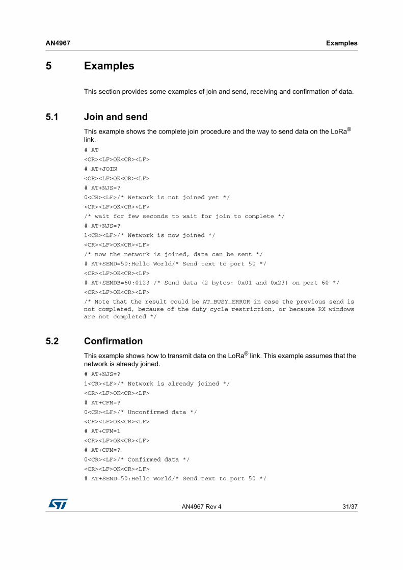
5 Examples
This section provides some examples of join and send, receiving and confirmation of data.
5.1 Join and send
This example shows the complete join procedure and the way to send data on the LoRa® link.
# AT
<CR><LF>OK<CR><LF>
# AT+JOIN
<CR><LF>OK<CR><LF>
# AT+NJS=?
0<CR><LF>/* Network is not joined yet */
<CR><LF>OK<CR><LF>
/* wait for few seconds to wait for join to complete */
# AT+NJS=?
1<CR><LF>/* Network is now joined */
<CR><LF>OK<CR><LF>
/* now the network is joined, data can be sent */
# AT+SEND=50:Hello World/* Send text to port 50 */
<CR><LF>OK<CR><LF>
# AT+SENDB=60:0123 /* Send data (2 bytes: 0x01 and 0x23) on port 60 */
<CR><LF>OK<CR><LF>
/* Note that the result could be AT_BUSY_ERROR in case the previous send is not completed, because of the duty cycle restriction, or because RX windows are not completed */
5.2 Confirmation
This example shows how to transmit data on the LoRa® link. This example assumes that the network is already joined.
# AT+NJS=?
1<CR><LF>/* Network is already joined */
<CR><LF>OK<CR><LF>
# AT+CFM=?
0<CR><LF>/* Unconfirmed data */
<CR><LF>OK<CR><LF>
# AT+CFM=1
<CR><LF>OK<CR><LF>
# AT+CFM=?
0<CR><LF>/* Confirmed data */
<CR><LF>OK<CR><LF>
# AT+SEND=50:Hello World/* Send text to port 50 */
Examples AN4967
32/37 AN4967 Rev 4
<CR><LF>OK<CR><LF>
# AT+CFS=?
0<CR><LF>/* Message is not confirmed yet */
<CR><LF>OK<CR><LF>
/* wait for few seconds to wait for the confirmation */
# AT+CFS=?
# AT+NJS=?
1<CR><LF>/* Network is already joined */
<CR><LF>OK<CR><LF>
# AT+CFM=?
0<CR><LF>/* Unconfirmed data */
<CR><LF>OK<CR><LF>
# AT+CFM=1
<CR><LF>OK<CR><LF>
# AT+CFM=?
0<CR><LF>/* Confirmed data */
<CR><LF>OK<CR><LF>
# AT+SEND=50:Hello World/* Send text to port 50 */
<CR><LF>OK<CR><LF>
# AT+CFS=?
0<CR><LF>/* Message is not confirmed yet */
<CR><LF>OK<CR><LF>
/* wait for few seconds to wait for the confirmation */
# AT+CFS=?
AN4967 Rev 4 33/37
AN4967 Examples
36
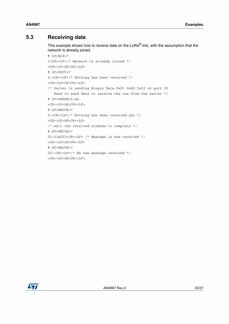
5.3 Receiving data
This example shows how to receive data on the LoRa® link, with the assumption that the network is already joined.
# AT+NJS=?
1<CR><LF>/* Network is already joined */
<CR><LF>OK<CR><LF>
# AT+RECV=?
0:<CR><LF>/* Nothing has been received */
<CR><LF>OK<CR><LF>
/* Server is sending Binary Data 0x01 0xA0 0x23 on port 20
Need to send data to receive the one from the server */
# AT+SENDB=2:ab
<CR><LF>OK<CR><LF>
# AT+RECVB=?
0:<CR><LF>/* Nothing has been received yet */
<CR><LF>OK<CR><LF>
/* wait the received windows to complete */
# AT+RECVB=?
20:01a023<CR><LF> /* Message is now received */
<CR><LF>OK<CR><LF>
# AT+RECVB=?
20:<CR><LF>/* No new message received */
<CR><LF>OK<CR><LF>
Embedded software description AN4967
34/37 AN4967 Rev 4
6 Embedded software description
This section gives an overview of the firmware architecture of the B-L072Z-LRWAN1 Discovery board. To see the complete description of the LoRa® embedded expansion software implementation I-CUBE-LRWAN refer to document 2.
6.1 Firmware overview
This overview refers to the software expansion for STM32Cube (see document 2) and not to the specific implementation of the LoRa® technology. For more details on how to proceed with the specific LoRa® technology case refer to document 2).
The AT command processing is found in the source files listed below:
• command.c: contains the definition and handlers of all the commands
• at.c: contains AT driver functions (basic action to provide what to whom)
6.2 LPUART
The AT commands are sent through an UART carrier. In order to optimize the low power, the LPUART of the B-L072Z-LRWAN1 Discovery board is used.
The AT_slave module executes two different tasks:
• LoRa® tasks: it manages the received windows, and it sends data
• Receives commands from the master that schedules LoRa® tasks, and then send back the requested value and the status of the command.
As the AT_slave is already executing the two tasks described above, the MCU is idle most of the time. The MCU remains waiting either for a command from the master or for a LoRa® task schedule.
So it is important to be in Stop Mode in order to optimize the low-level power of the MCU. As commands are received through the UART, the low power UART (LPUART) is being used, hence the communication transfer rate is limited to 9600 bauds.
The LPUART is initialized to be enabled in Stop Mode, and the wake up from Stop Mode is performed on a Start bit detection. The LPUART handler (vcom_IRQHandler()) enables RXNE (RX not empty) IT, so that when RXNE IT is raised, the character is read and stored in an internal circular buffer.
The buffer of read characters is then processed in the normal thread (not in the IT thread). A command is recognized when the new character received is <CR> or <LF>.
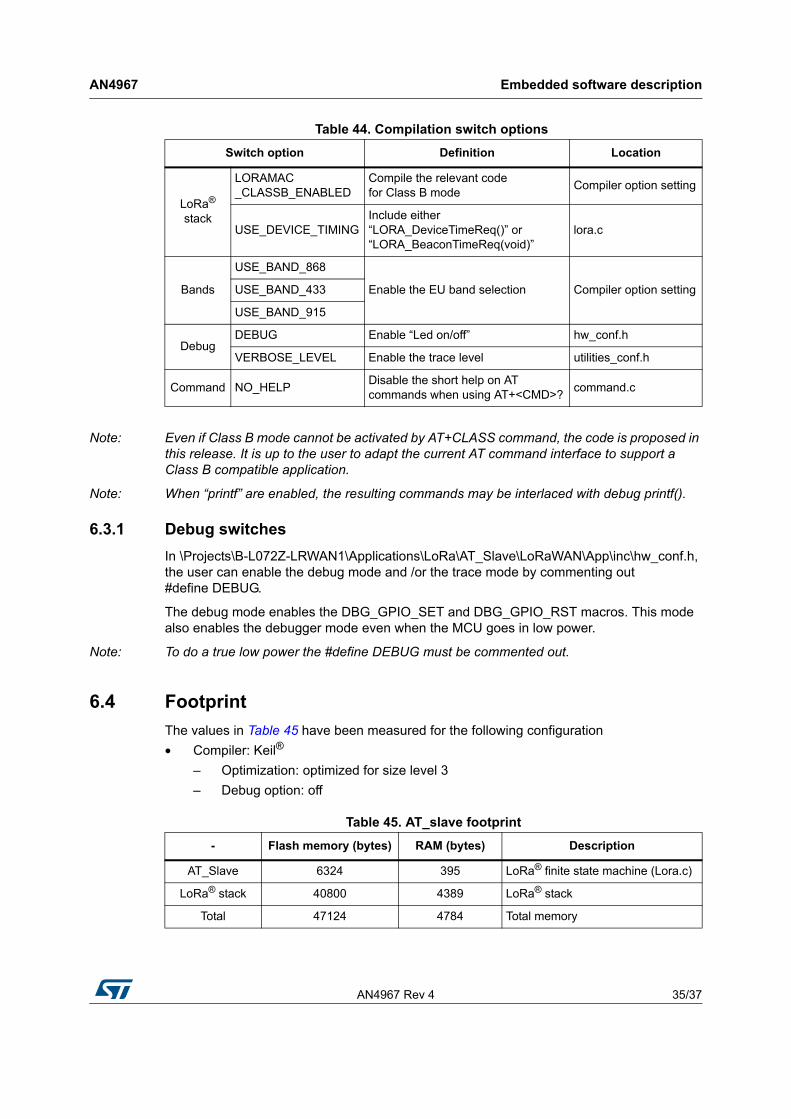
6.3 Compilation switches
This section lists the compilation switches provided to the user to control the compilation process.
Table 44 provides a summary of the main options for the application configuration.
AN4967 Rev 4 35/37
AN4967 Embedded software description
36
Note: Even if Class B mode cannot be activated by AT+CLASS command, the code is proposed in this release. It is up to the user to adapt the current AT command interface to support a Class B compatible application.
Note: When “printf” are enabled, the resulting commands may be interlaced with debug printf().
6.3.1 Debug switches
In \Projects\B-L072Z-LRWAN1\Applications\LoRa\AT_Slave\LoRaWAN\App\inc\hw_conf.h, the user can enable the debug mode and /or the trace mode by commenting out #define DEBUG.
The debug mode enables the DBG_GPIO_SET and DBG_GPIO_RST macros. This mode also enables the debugger mode even when the MCU goes in low power.
Note: To do a true low power the #define DEBUG must be commented out.
6.4 Footprint
The values in Table 45 have been measured for the following configuration
• Compiler: Keil®
– Optimization: optimized for size level 3
– Debug option: off
Table 44. Compilation switch options
Switch option Definition Location
LoRa® stack
LORAMAC _CLASSB_ENABLED
Compile the relevant code for Class B mode
Compiler option setting
USE_DEVICE_TIMINGInclude either “LORA_DeviceTimeReq()” or “LORA_BeaconTimeReq(void)”
lora.c
Bands
USE_BAND_868
Enable the EU band selection Compiler option settingUSE_BAND_433
USE_BAND_915
DebugDEBUG Enable “Led on/off” hw_conf.h
VERBOSE_LEVEL Enable the trace level utilities_conf.h
Command NO_HELPDisable the short help on AT commands when using AT+<CMD>?
command.c
Table 45. AT_slave footprint
- Flash memory (bytes) RAM (bytes) Description
AT_Slave 6324 395 LoRa® finite state machine (Lora.c)
LoRa® stack 40800 4389 LoRa® stack
Total 47124 4784 Total memory
Revision history AN4967
36/37 AN4967 Rev 4
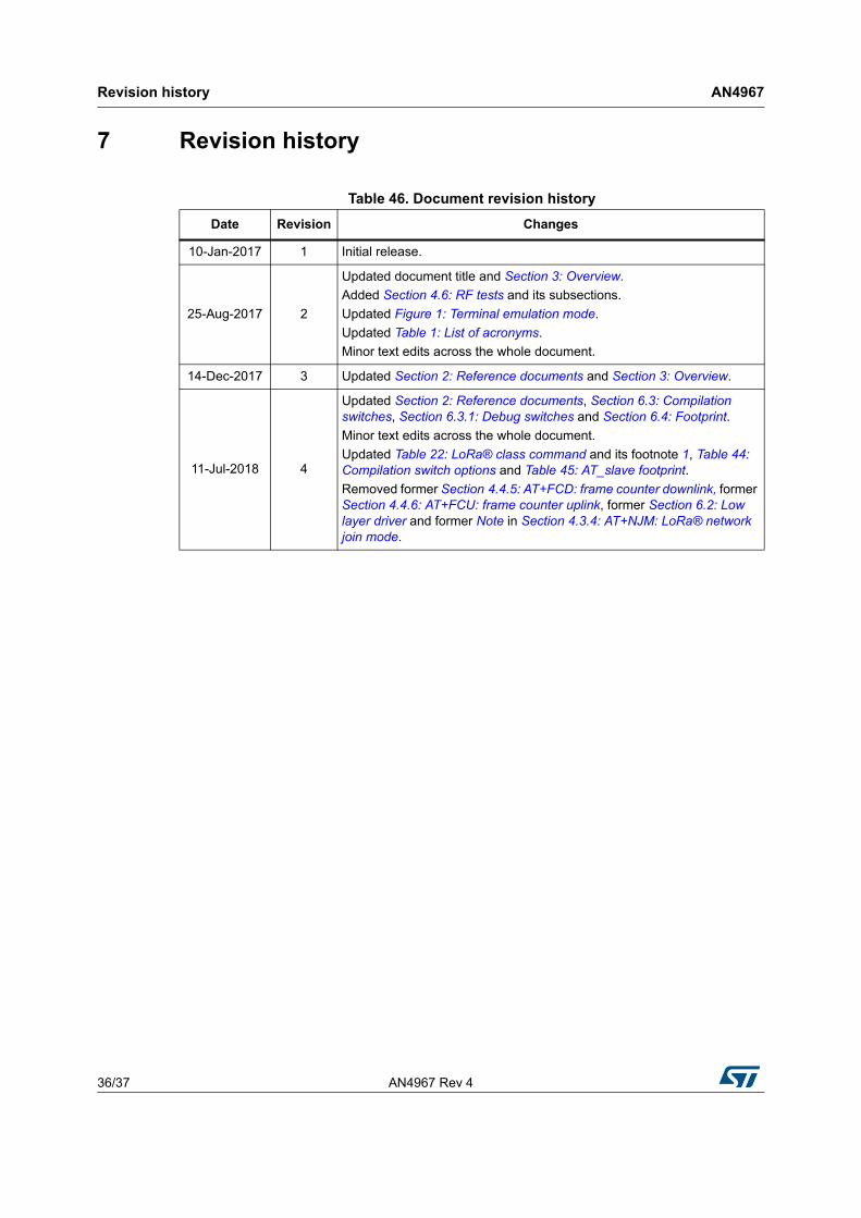
7 Revision history
Table 46. Document revision history
Date Revision Changes
10-Jan-2017 1 Initial release.
25-Aug-2017 2
Updated document title and Section 3: Overview.
Added Section 4.6: RF tests and its subsections.
Updated Figure 1: Terminal emulation mode.
Updated Table 1: List of acronyms.
Minor text edits across the whole document.
14-Dec-2017 3 Updated Section 2: Reference documents and Section 3: Overview.
11-Jul-2018 4
Updated Section 2: Reference documents, Section 6.3: Compilation switches, Section 6.3.1: Debug switches and Section 6.4: Footprint.
Minor text edits across the whole document.
Updated Table 22: LoRa® class command and its footnote 1, Table 44: Compilation switch options and Table 45: AT_slave footprint.
Removed former Section 4.4.5: AT+FCD: frame counter downlink, former Section 4.4.6: AT+FCU: frame counter uplink, former Section 6.2: Low layer driver and former Note in Section 4.3.4: AT+NJM: LoRa® network join mode.
AN4967 Rev 4 37/37
AN4967
37
IMPORTANT NOTICE – PLEASE READ CAREFULLY
STMicroelectronics NV and its subsidiaries (“ST”) reserve the right to make changes, corrections, enhancements, modifications, and improvements to ST products and/or to this document at any time without notice. Purchasers should obtain the latest relevant information on ST products before placing orders. ST products are sold pursuant to ST’s terms and conditions of sale in place at the time of order acknowledgement.
Purchasers are solely responsible for the choice, selection, and use of ST products and ST assumes no liability for application assistance or the design of Purchasers’ products.
No license, express or implied, to any intellectual property right is granted by ST herein.
Resale of ST products with provisions different from the information set forth herein shall void any warranty granted by ST for such product.
ST and the ST logo are trademarks of ST. All other product or service names are the property of their respective owners.
Information in this document supersedes and replaces information previously supplied in any prior versions of this document.
© 2018 STMicroelectronics – All rights reserved


![Misc commands[1]](https://img.pdfslide.tips/doc/110x75/55c2d092bb61eb64298b458d/misc-commands1-55c485220ba26.jpg)