Embed Size (px)
Citation preview
322 TEKSTİL ve KONFEKSİYON 29(4), 2019
TEKSTİL VE KONFEKSİYON
Vol: 29, No: 4
DOI: 10.32710/tekstilvekonfeksiyon.495322
Experimental and Numerical Study of Sewing Seams
of Automobile Seat Covers Under Unidirectional
and Multiaxial Loading
Natalia Kovalova1, Petr Kulhavý2, Josef Vosáhlo2, Antonin Havelka1 *
1 Technical University of Liberec, Faculty of Textile Engineering, Studentska 2, 46117 Liberec 1, Czech Republic 2 Technical University of Liberec, Institute for Nanomaterials, Advanced Technologies and Innovation, Studentská 2, 46117 Liberec 1,
Czech Republic
Corresponding Author: Natalia Kovalova, [email protected]
ABSTRACT
In industrial textiles, knowing the exact characteristics and behaviour of materials is important. For
car seats, industrial textiles not just cover the underlying foam but also increase rigidity of the seat
cushion and influence viscoelastic behaviours of foams. Moreover, strength of sewn seams is one of
the main quality parameters. Herein, four polyester and polyamide threads were sewn on a material
used for car seat covers through lockstitch sewing. Combinations of these materials were studied
using static tests in the unidirectional and multiaxial variants. The experimental measurements
recorded using a high-speed camera and computer tomography were used to create CAD models.
Numerical simulations were conducted using these models and the obtained material models. These
model studies help predict and describe the stresses emerging within various types of textile and the
threads in their connections. The simulation results agree well with the experimental results.
ARTICLE HISTORY
Received: 11.12.2018
Accepted: 01.10.2019
KEYWORDS
sewing seam; strength, 3D
curves, parts contact,
numerical model
1. INTRODUCTION
Automotive textiles represent the most valuable market
worldwide for technical textiles. Within this segment, a
broad spectrum of products having novel textile structures
with performance properties and attractive design is
available [1]. Car seat covers are perhaps the most familiar
automotive textiles. Considerable technical input is
necessary to develop materials that must withstand rigorous
use (and abuse) and yet last for the lifetime of the car seat
[2].
The exact knowledge about mechanical properties of the
used materials is the basic prerequisite for successful
product construction. The mechanical properties of
materials play a crucial role in the control of production
technology, quality control and development of new
materials. In addition, in a few cases, human life may be
placed in danger owing due to a malfunction of these
products (such as parachutes, airbags, and safety belts).
Therefore, it is necessary to understand not only the
strength characteristics of textile materials and threads but
also the performance of seams.
The seam characteristics include strength, elasticity,
durability, safety, and appearance. Inconsistencies in these
characteristics can lead to significant differences in seam
behavior and can affect seam deformation characteristics.
These characteristics originate from four principal sources:
speed, needle, thread, and fabric. It has been found that
fundamental interactions among these factors exist [3].
Mazari et. al. [4] confirmed that the friction between the
needle and sewing thread is one of the major sources of
To cite this article: Kovalova N, Kulhyvy P, Vosahlo J, Havelka A. 2019. Experimental and numerical study of sewing seams
of automobile seat covers under unidirectional and multiaxial loading Tekstil ve Konfeksiyon 29 (4),322-335.
TEKSTİL ve KONFEKSİYON 29(4), 2019 323
needle heating. High needle temperature during sewing
weakens the thread because thread tensile strength is a
function of temperature as well, and this leads to decreased
production. In addition, the strength of the final stitched
thread is 30–40 % lower than that of the parent threads. A
very high needle temperature can damage the materials as
well, for example, a few synthetic fabrics or plastics that
come into direct contact with the needle during sewing. Zak
[5] described the principles of mutual fabric interaction by
using Pierce’s model and numerically by using the finite
element method (FEM).
According to Midha [6], during high-speed sewing, the
strength of sewing threads decreases substantially. Any
change in thread strength is closely connected to the
thread’s passage over the guiding elements of the sewing
machine and, consequently, the friction and bending
originating between the needle’s thread and the touching
areas, as well as friction with the bobbin thread [7]. These
pressure and friction forces result from internal tension.
One of the major quality factor associated with seams is
fabric type. At present, different types of materials are used
for upholstering car seats. These include technical textiles
for car seat covers, such as woven, knitted, and nonwoven
fabrics; natural and artificial leather from synthetic
polymers such as polyester, polyamide, and viscose; and
blends of wool and cotton with synthetic fibres. Woven and
knitted structures are two main fabric forming methods
used for manufacturing car seat upholstery manufacturer
[8]. Ujevic et al. [9] studied the influence of fabric type on
the mechanical properties of the seam, and they found that
technical woven fabrics have higher breaking force and
penetration resistance than knitted fabric, but knitted fabric
is softer and more elastic. Sewing thread accounts for a
small percentage of the final product cost but accounts for
50% of the seam strength. Hence, thread plays an important
role in seam quality, especially in car seat covers, where it
is necessary to consider the following factors: thread fiber
type, thread construction, thread finish, and thread size.
For creating a high-quality seam it is necessary to consider
all abovementioned parameters. This is a fairly time-
consuming process because of the wide variety of existing
materials. Therefore, the aim of this study is to develop a
numerical model of sewing seams considering all necessary
parameters. When studying literature and the latest world
research, it is possible to find some numerical models that
relate to the textiles connections, however they are
simplified by local homogenization of the entire seam as
one local area with usually orthotropic properties or some
studies of just small segment of the yarn. No model that
interprets the thread in its entirety, including individual
yarn twists and holes in the fabric has been found.
There are many types of fabric constructions used in
automobiles as seat cover fabrics. One type of twill fabric
and four types of sewing threads were used for
determination of the mechanical properties with using
different measuring methods. Together with that, twill
fabric type and one type of polyamide sewing thread were
used for creating numerical model of sewing seam. The
twill fabric used is the most common fabric used by
researchers and its possible to compare with the findings of
the previous researchers. In future the numerical model can
be tested for multiple textile fabrics.
The required material properties have been measured using
a designed multiaxial apparatus. Seam strength was
determined by conducting the standard uniaxial static
experiments. However, because automobile seat covers are
subjected to various loadings, especially, multi-axis load, a
special testing device was designed and constructed [3,10].
This device operates on the principle of extrusion of a
spherical cap into a cylindrically clamped sample. Each
type of test was recorded on a high-speed camera and the
samples before and after testing were screened using
computer tomography to obtain precise geometric
parameters of the created CAD model. Based on this CAD
geometry and by using the commercial software ANSYS,
several nonlinear contact numerical simulations were
conducted to predict the behaviour of the stitched seams
instead of the classical experiments [11]. Therefore, the
main aim of this article is to thoroughly describe the
behaviour of stitched seams for various textile materials
and various loading conditions, as well as to develop the
corresponding simulation model that can predict the real
behaviour of a selected combination of threads and fibres
instead of having to conduct expensive experiments.
2. MATERIAL AND METHOD
2.1 Material
During the process of product usage, sewn seams and
materials are subjected to variable loads, leading to various
deformations. For textile materials, which show
considerable anisotropy or orthotropy, testing along one
axis is generally insufficient, and it is necessary to load two
axes simultaneously. According to Quaglini [12], because
of the small thickness of fabric, it is usually a neglected
component of strain along the thickness direction of the
material, and technical textiles are mainly thought to be
affected by plane stress [13,14].
2.1.1 Threads
To investigate the effect of different sewing threads on
seam strength, four different threads were used for
specimen preparation (Table 1). Threads of Type B, Type
C, Type H, and Type M1 were used to investigate seam
strength under multiaxial loading. Other types of threads
were used for static measurements. These threads are
commonly used in the industry to sew car seat covers.
According to ISO 2060 [15] and ISO 2061 [16], the values
of fineness and twist of the sewing threads were
investigated experimentally.
324 TEKSTİL ve KONFEKSİYON 29(4), 2019
For preparing all samples tested in this study, seam
parameters were selected precisely, and the sewing machine
was set up accordingly. A Dürkop Adler sewing machine
with an upper thread tension of 4 N and lower thread
tension of 1 N was used. Classes of seams and stitching are
defined in the international standards ISO 4916 and ISO
4915 respectively. The parameters of the sewing process
were as follows: superimposed seam with width of 10 mm
and 301 Lockstitch with a density of 3.3 mm. These
parameters of stitches and seams are most commonly used
for sewing car seat covers.
2.1.2 Fabric
Sandwich-type fabrics are used for preparing samples to
test the mechanical properties of sewing seams under
different type of loading. The material consists of the PES
face fabric, foam core and the weft knit fabric as the back.
Material thickness was defined using the method given in
the standard ISO 5084 [17]. The exact parameters of the
fabric are listed in Table 2.
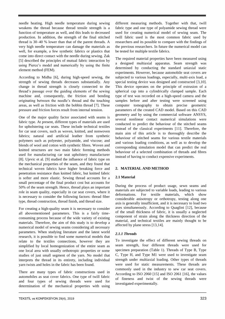
2.1.3 Experimental samples for unidirectional
and multiaxial loading
The samples for uniaxial loading were prepared according
to the norm CSN EN ISO 13935-1 [18]. Laboratory
samples of size 700 mm × 350 mm were prepared of the
material used to industrial manufacturing of car seat covers
(Figure 1a). The samples were folded, such that the edge of
the fold was parallel to the shorter side of the sample. The
samples were prepared in the warp and the weft directions.
Finally, the real width of the sample was 50 mm, and the
length of the sample used for investigation was 330 mm
(Figure 1b).
The production of experimental samples for measuring
seam strength under multiaxial stress begins in the same
way as that for uniaxial stress. Parts of the fabric are sewn
together, and the remaining parts are prepared for each set
of experiment on the test samples by cutting out the desired
shapes (Figure 1b). The shaded area in Figure 1b shows the
portion of the test sample on which the spherical cup is
pushed [19].
Figure 1. Laboratory specimens: a) The UD sample and b)
experimental sample
2.2 Experimental Devices and Methods
As Reinhardt pointed out [20], in terms of textile testing,
the materials are almost always loaded and should be tested
biaxially. According to Novak and Hanus [21], anisotropic
materials such as the tested coating materials show
noticeable hysteresis and different deformations according
along different loading directions owing to specific
mechanical properties. In tensile tests of textiles along one
axis in the longitudinal direction, the main stress
concentrators are formed, and the fabric subsequently
ruptures near the clamping jaws. By contrast, the tension
along the transverse direction is more uniformly
concentrated at the sample centre.
According to Escárpita [22], testing of multiaxial loaded
samples is necessary to ensure that the test device meets the
basic requirements. There must be strictly tension or
compression, and spurious shear or bending loads must be
avoided. Generally, the use of a hydraulic or mechanical
system comprising linear motors, cable system, pulleys, and
bearings is recommended.
Table 1. Properties of threads used in this study
Property Type B Type C Type H Type M1
Tread content PA6.6 PA6.6 PES PES
Actual thread density T [Tex] 107.8 79.0 94.8 78.7
Twist [t/m] 347 409 375 416
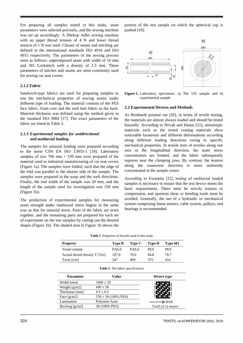
Table 2. The fabric specifications
Parameter Value Weave type
Width [mm] 1800 ± 20
Weft
Twill (2/1) weave
Weight [g/m2] 490 ± 50
Thickness [mm] 4.5 ± 0.5
Face [g/m2] 330 ± 30 (100% PES)
Lamination Polyester foam
Backing [g/m2] 38 (100% PES)
TEKSTİL ve KONFEKSİYON 29(4), 2019 325
In the tests, a sample of certain dimensions with the seam in
the middle is stretched in a direction perpendicular to the
seam at a constant rate until seam breakage.
2.2.1 Unidirectional tests
The most common tests applied to automotive seat
upholstery were specified by the Society of Automotive
Engineers (SAE) and the American Society for Testing
Material (ASTM) [23]. For determining the mechanical
properties associated with seam sewing, the Strip tests [18]
are used. For these experiments, it was necessary to select
and condition the samples according to the standard ISO
139 [24].
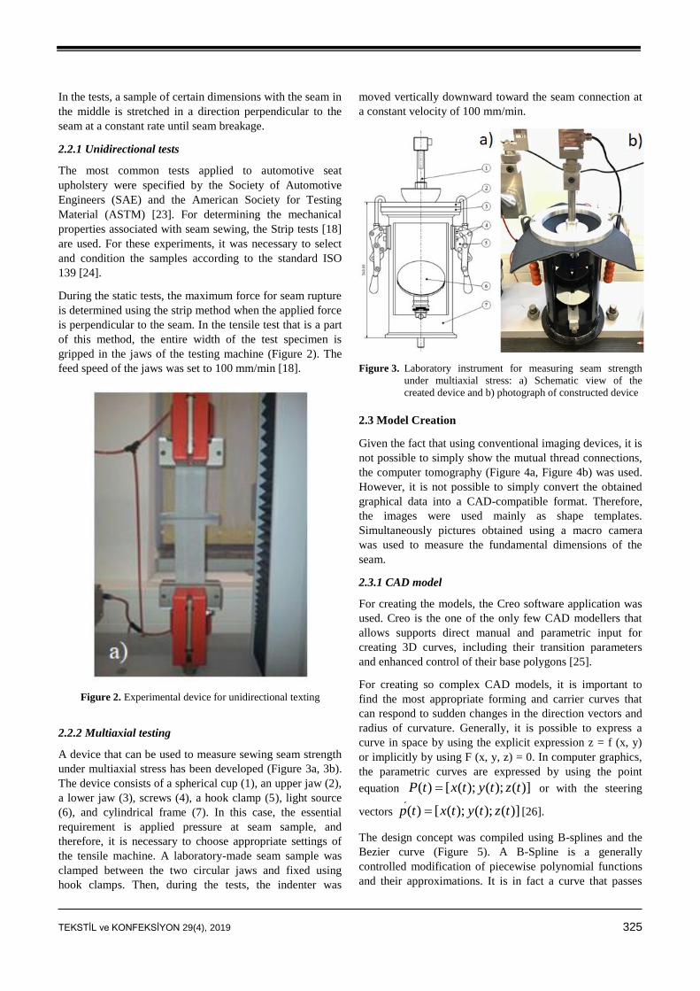
During the static tests, the maximum force for seam rupture
is determined using the strip method when the applied force
is perpendicular to the seam. In the tensile test that is a part
of this method, the entire width of the test specimen is
gripped in the jaws of the testing machine (Figure 2). The
feed speed of the jaws was set to 100 mm/min [18].
Figure 2. Experimental device for unidirectional texting
2.2.2 Multiaxial testing
A device that can be used to measure sewing seam strength
under multiaxial stress has been developed (Figure 3a, 3b).
The device consists of a spherical cup (1), an upper jaw (2),
a lower jaw (3), screws (4), a hook clamp (5), light source
(6), and cylindrical frame (7). In this case, the essential
requirement is applied pressure at seam sample, and
therefore, it is necessary to choose appropriate settings of
the tensile machine. A laboratory-made seam sample was
clamped between the two circular jaws and fixed using
hook clamps. Then, during the tests, the indenter was
moved vertically downward toward the seam connection at
a constant velocity of 100 mm/min.
Figure 3. Laboratory instrument for measuring seam strength
under multiaxial stress: a) Schematic view of the
created device and b) photograph of constructed device
2.3 Model Creation
Given the fact that using conventional imaging devices, it is
not possible to simply show the mutual thread connections,
the computer tomography (Figure 4a, Figure 4b) was used.
However, it is not possible to simply convert the obtained
graphical data into a CAD-compatible format. Therefore,
the images were used mainly as shape templates.
Simultaneously pictures obtained using a macro camera
was used to measure the fundamental dimensions of the
seam.
2.3.1 CAD model
For creating the models, the Creo software application was
used. Creo is the one of the only few CAD modellers that
allows supports direct manual and parametric input for
creating 3D curves, including their transition parameters
and enhanced control of their base polygons [25].
For creating so complex CAD models, it is important to
find the most appropriate forming and carrier curves that
can respond to sudden changes in the direction vectors and
radius of curvature. Generally, it is possible to express a
curve in space by using the explicit expression z = f (x, y)
or implicitly by using F (x, y, z) = 0. In computer graphics,
the parametric curves are expressed by using the point
equation ( ) [ ( ); ( ); ( )]P t x t y t z t or with the steering
vectors ( ) [ ( ); ( ); ( )]p t x t y t z t [26].
The design concept was compiled using B-splines and the
Bezier curve (Figure 5). A B-Spline is a generally
controlled modification of piecewise polynomial functions
and their approximations. It is in fact a curve that passes
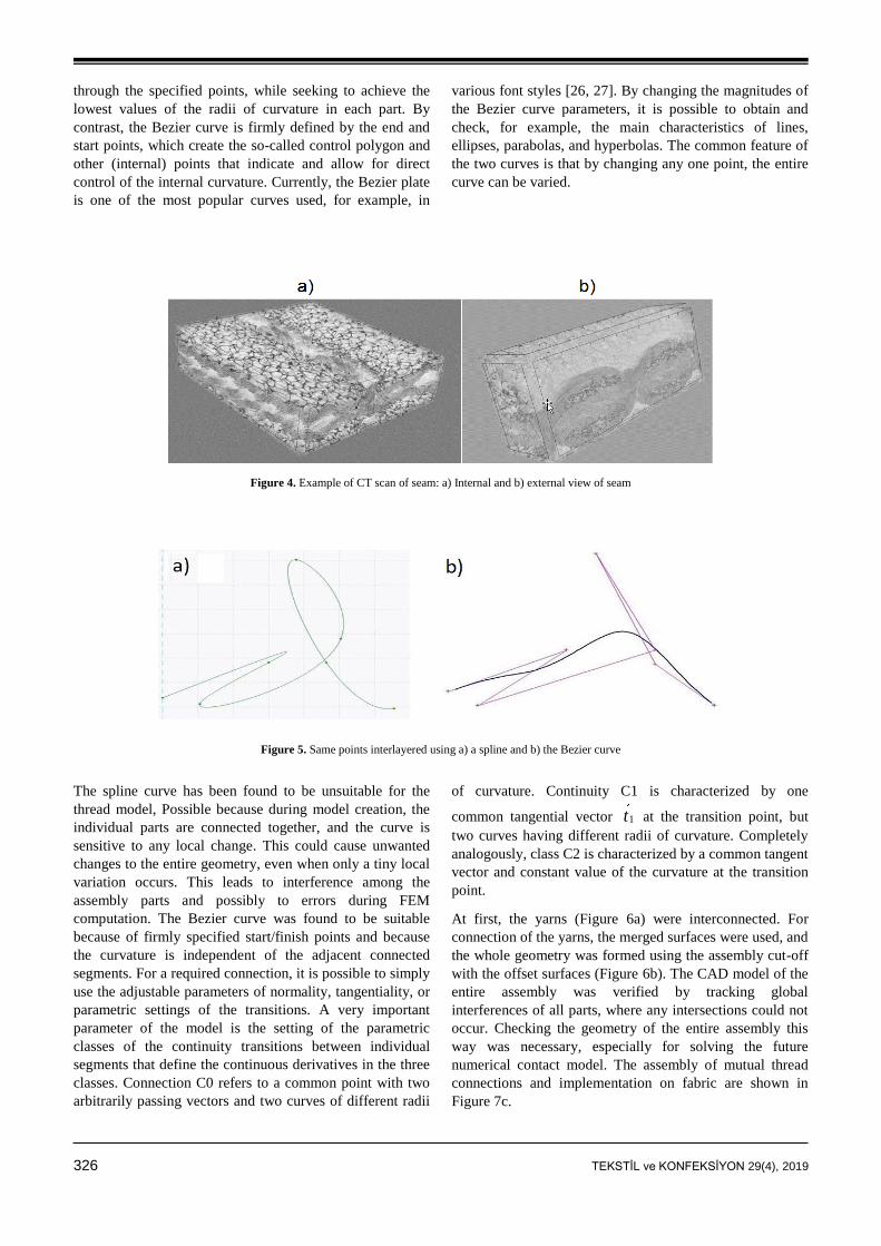
326 TEKSTİL ve KONFEKSİYON 29(4), 2019
through the specified points, while seeking to achieve the
lowest values of the radii of curvature in each part. By
contrast, the Bezier curve is firmly defined by the end and
start points, which create the so-called control polygon and
other (internal) points that indicate and allow for direct
control of the internal curvature. Currently, the Bezier plate
is one of the most popular curves used, for example, in
various font styles [26, 27]. By changing the magnitudes of
the Bezier curve parameters, it is possible to obtain and
check, for example, the main characteristics of lines,
ellipses, parabolas, and hyperbolas. The common feature of
the two curves is that by changing any one point, the entire
curve can be varied.
Figure 4. Example of CT scan of seam: a) Internal and b) external view of seam
Figure 5. Same points interlayered using a) a spline and b) the Bezier curve
The spline curve has been found to be unsuitable for the
thread model, Possible because during model creation, the
individual parts are connected together, and the curve is
sensitive to any local change. This could cause unwanted
changes to the entire geometry, even when only a tiny local
variation occurs. This leads to interference among the
assembly parts and possibly to errors during FEM
computation. The Bezier curve was found to be suitable
because of firmly specified start/finish points and because
the curvature is independent of the adjacent connected
segments. For a required connection, it is possible to simply
use the adjustable parameters of normality, tangentiality, or
parametric settings of the transitions. A very important
parameter of the model is the setting of the parametric
classes of the continuity transitions between individual
segments that define the continuous derivatives in the three
classes. Connection C0 refers to a common point with two
arbitrarily passing vectors and two curves of different radii
of curvature. Continuity C1 is characterized by one
common tangential vector 1t at the transition point, but
two curves having different radii of curvature. Completely
analogously, class C2 is characterized by a common tangent
vector and constant value of the curvature at the transition
point.
At first, the yarns (Figure 6a) were interconnected. For
connection of the yarns, the merged surfaces were used, and
the whole geometry was formed using the assembly cut-off
with the offset surfaces (Figure 6b). The CAD model of the
entire assembly was verified by tracking global
interferences of all parts, where any intersections could not
occur. Checking the geometry of the entire assembly this
way was necessary, especially for solving the future
numerical contact model. The assembly of mutual thread
connections and implementation on fabric are shown in
Figure 7c.
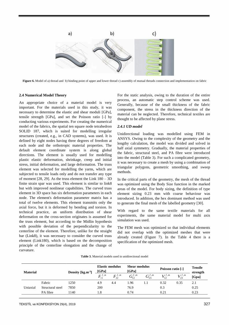
TEKSTİL ve KONFEKSİYON 29(4), 2019 327
Figure 6. Model of a) thread and b) binding point of upper and lower thread c) assembly of mutual threads connection and implementation on fabric
2.4 Numerical Model Theory
An appropriate choice of a material model is very
important. For the materials used in this study, it was
necessary to determine the elastic and shear moduli [GPa],
tensile strength [GPa], and set the Poisson ratio [-] by
conducting various experiments. For creating the numerical
model of the fabrics, the spatial ten square node tetrahedron
SOLID 187, which is suited for modelling irregular
structures (created, e.g., in CAD systems), was used. It is
defined by eight nodes having three degrees of freedom at
each node and the orthotropic material properties. The
default element coordinate system is along global
directions. The element is usually used for modelling
plastic elastic deformation, shrinkage, creep and initial
stress, initial deformation, and large deformation. The truss
element was selected for modelling the yarns, which are
subjected to tensile loads only and do not transfer any type
of moment [28, 29]. As the truss element the Link 180 – 3D
finite strain spar was used. This element is similar to link8
but with improved nonlinear capabilities. The curved truss
element in 3D space has six deformation parameters in each
node. The element's deformation parameter matrix has a
total of twelve elements. This element transmits only the
axial force, but it is deformed by bending and torsion. In
technical practice, an uniform distribution of shear
deformation on the cross-section originates is assumed for
the truss element, but according to the Midlin hypothesis
with possible deviation of the perpendicularity to the
centerline of the element. Therefore, unlike for the straight
bar (Link8), it was necessary to consider the curved truss
element (Link180), which is based on the decomposition
principle of the centerline elongation and the change of
curvature.
For the static analysis, owing to the duration of the entire
process, an automatic step control scheme was used.
Generally, because of the small thickness of the fabric
component, the stress in the thickness direction of the
material can be neglected. Therefore, technical textiles are
thought to be affected by plane stress.
2.4.1 UD model
Unidirectional loading was modelled using FEM in
ANSYS. Owing to the complexity of the geometry and the
lengthy calculation, the model was divided and solved in
half axial symmetry. Gradually, the material properties of
the fabric, structural steel, and PA fibre were introduced
into the model (Table 3). For such a complicated geometry,
it was necessary to create a mesh by using a combination of
triangular polygons, geometric smoothing, and sweep
methods.
In the critical parts of the geometry, the mesh of the thread
was optimized using the Body Size function in the marked
areas of the model. For body sizing, the definition of type
element sizing 0.23 mm with coarse behaviour was
introduced. In addition, the hex dominant method was used
to generate the final mesh of the labelled geometry [30].
With regard to the same textile materials for all
experiments, the same material model for multi axis
simulation was used.
The FEM mesh was optimized so that individual elements
did not overlap with the optimized meshes that were
already created (Figure 7). In the Table 4 there is a
specification of the optimized mesh.
Table 3. Material models used in unidirectional model
Material Density [kg.m-3]
Elastic modulus
[GPa]
Shear modulus
[GPa] Poisson ratio [-] Tensile
strength
[Gpa] ,
11
f mF
,
22
f mF
,
12
f mG ,
23
f mG ,
12
f mV ,
23
f mV
Uniaxial
Fabric 1250 4.9 4.4 1.96 1.1 0.32 0.35 2.1
Structural steel 7850 200 76.9 0.3 0.25
PA fibre 1140 1.8 0.74 0.21 0.23
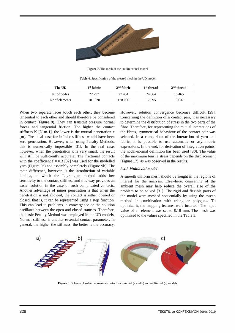
328 TEKSTİL ve KONFEKSİYON 29(4), 2019
Figure 7. The mesh of the unidirectional model
Table 4. Specification of the created mesh in the UD model
The UD 1st fabric 2nd fabric 1st thread 2nd thread
Nr of nodes 22 797 27 454 24 864 16 465
Nr of elements 101 620 128 000 17 595 10 637
When two separate faces touch each other, they become
tangential to each other and should therefore be considered
in contact (Figure 8). They can transmit pressure normal
forces and tangential friction. The higher the contact
stiffness K [N m-1], the lower is the mutual penetration x
[m]. The ideal case for infinite stiffness would have been
zero penetration. However, when using Penalty Methods,
this is numerically impossible [31]. In the real case,
however, when the penetration x is very small, the result
will still be sufficiently accurate. The frictional contacts
with the coefficient f = 0.3 [32] was used for the modelled
yarn (Figure 9a) and assembly completely (Figure 9b). The
main difference, however, is the introduction of variable
lambda, in which the Lagrangian method adds low
sensitivity to the contact stiffness and this way provides an
easier solution in the case of such complicated contacts.
Another advantage of minor penetration is that when the
penetration is not allowed, the contact is either opened or
closed, that is, it can be represented using a step function.
This can lead to problems in convergence or the solution
oscillates between the open and closed statuses. Therefore,
the basic Penalty Method was employed in the UD models.
Normal stiffness is another essential contact parameter. In
general, the higher the stiffness, the better is the accuracy.
However, solution convergence becomes difficult [29].
Concerning the definition of a contact pair, it is necessary
to determine the distribution of stress in the two parts of the
fibre. Therefore, for representing the mutual interactions of
the fibres, symmetrical behaviour of the contact pair was
selected. In a comparison of the interaction of yarn and
fabric, it is possible to use automatic or asymmetric
expressions. In the end, for derivation of integration points,
the nodal-normal definition has been used [30]. The value
of the maximum tensile stress depends on the displacement
(Figure 17), as was observed in the results.
2.4.2 Multiaxial model
A smooth uniform mesh should be sought in the regions of
interest for the analysis. Elsewhere, coarsening of the
ambient mesh may help reduce the overall size of the
problem to be solved [31]. The rigid and flexible parts of
the model were meshed sequentially by using the sweep
method in combination with triangular polygons. To
optimize it, the mapping features were inserted. The input
value of an element was set to 0.18 mm. The mesh was
optimized to the values specified in the Table 5.
Figure 8. Scheme of solved numerical contact for uniaxial (a and b) and multiaxial (c) models
TEKSTİL ve KONFEKSİYON 29(4), 2019 329
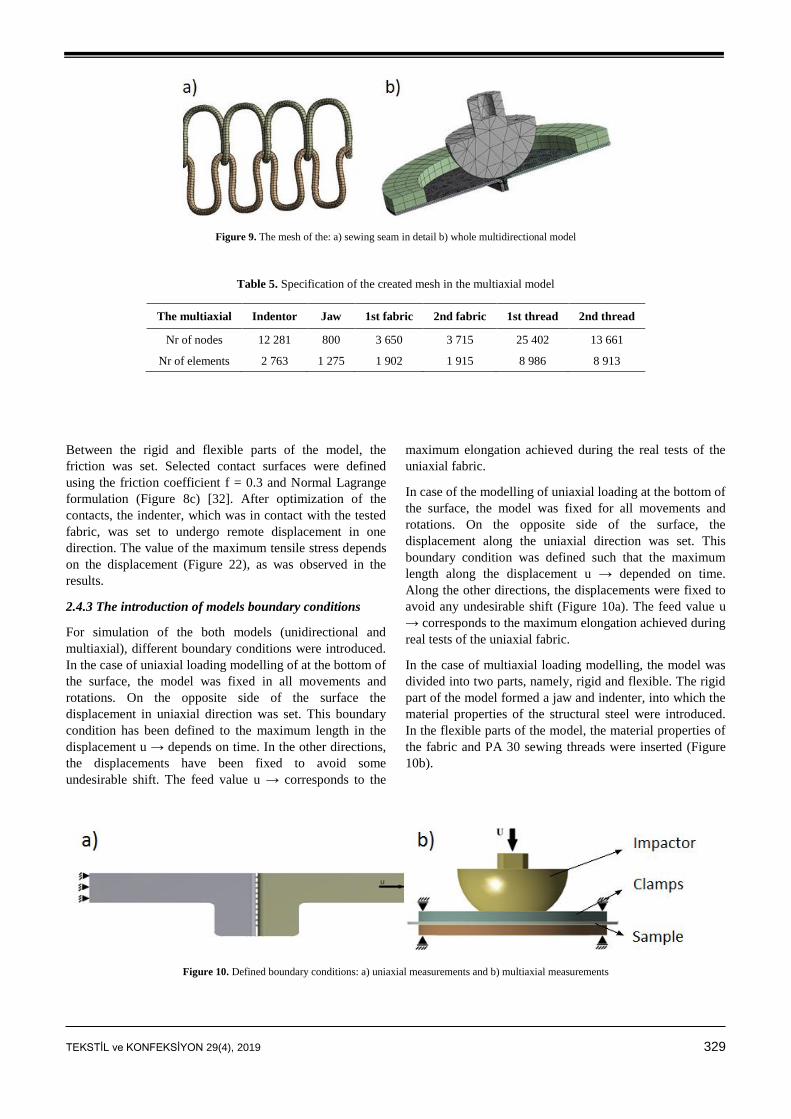
Figure 9. The mesh of the: a) sewing seam in detail b) whole multidirectional model
Table 5. Specification of the created mesh in the multiaxial model
The multiaxial Indentor Jaw 1st fabric 2nd fabric 1st thread 2nd thread
Nr of nodes 12 281 800 3 650 3 715 25 402 13 661
Nr of elements 2 763 1 275 1 902 1 915 8 986 8 913
Between the rigid and flexible parts of the model, the
friction was set. Selected contact surfaces were defined
using the friction coefficient f = 0.3 and Normal Lagrange
formulation (Figure 8c) [32]. After optimization of the
contacts, the indenter, which was in contact with the tested
fabric, was set to undergo remote displacement in one
direction. The value of the maximum tensile stress depends
on the displacement (Figure 22), as was observed in the
results.
2.4.3 The introduction of models boundary conditions
For simulation of the both models (unidirectional and
multiaxial), different boundary conditions were introduced.
In the case of uniaxial loading modelling of at the bottom of
the surface, the model was fixed in all movements and
rotations. On the opposite side of the surface the
displacement in uniaxial direction was set. This boundary
condition has been defined to the maximum length in the
displacement u → depends on time. In the other directions,
the displacements have been fixed to avoid some
undesirable shift. The feed value u → corresponds to the
maximum elongation achieved during the real tests of the
uniaxial fabric.
In case of the modelling of uniaxial loading at the bottom of
the surface, the model was fixed for all movements and
rotations. On the opposite side of the surface, the
displacement along the uniaxial direction was set. This
boundary condition was defined such that the maximum
length along the displacement u → depended on time.
Along the other directions, the displacements were fixed to
avoid any undesirable shift (Figure 10a). The feed value u
→ corresponds to the maximum elongation achieved during
real tests of the uniaxial fabric.
In the case of multiaxial loading modelling, the model was
divided into two parts, namely, rigid and flexible. The rigid
part of the model formed a jaw and indenter, into which the
material properties of the structural steel were introduced.
In the flexible parts of the model, the material properties of
the fabric and PA 30 sewing threads were inserted (Figure
10b).
Figure 10. Defined boundary conditions: a) uniaxial measurements and b) multiaxial measurements
330 TEKSTİL ve KONFEKSİYON 29(4), 2019
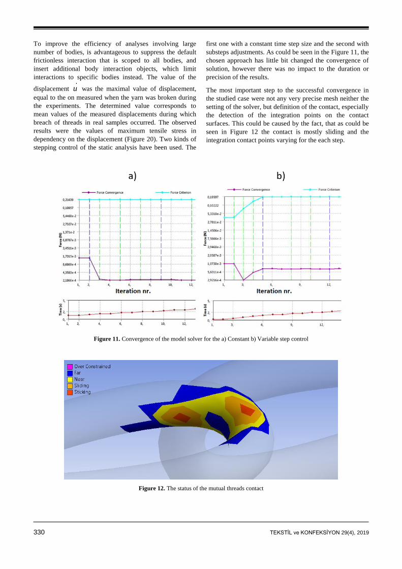
To improve the efficiency of analyses involving large
number of bodies, is advantageous to suppress the default
frictionless interaction that is scoped to all bodies, and
insert additional body interaction objects, which limit
interactions to specific bodies instead. The value of the
displacement u was the maximal value of displacement,
equal to the on measured when the yarn was broken during
the experiments. The determined value corresponds to
mean values of the measured displacements during which
breach of threads in real samples occurred. The observed
results were the values of maximum tensile stress in
dependency on the displacement (Figure 20). Two kinds of
stepping control of the static analysis have been used. The
first one with a constant time step size and the second with
substeps adjustments. As could be seen in the Figure 11, the
chosen approach has little bit changed the convergence of
solution, however there was no impact to the duration or
precision of the results.
The most important step to the successful convergence in
the studied case were not any very precise mesh neither the
setting of the solver, but definition of the contact, especially
the detection of the integration points on the contact
surfaces. This could be caused by the fact, that as could be
seen in Figure 12 the contact is mostly sliding and the
integration contact points varying for the each step.
Figure 11. Convergence of the model solver for the a) Constant b) Variable step control
Figure 12. The status of the mutual threads contact
TEKSTİL ve KONFEKSİYON 29(4), 2019 331
3. RESULTS AND DISCUSSION
In this work, the mechanical characteristics of seams were
analysed experimentally for various types of stresses. The
device that can be used to test seam strength and monitor
the mechanical characteristics of seams under multi-axial
loading was developed. Then also the experimental analysis
of the dynamic characteristics of the seam was performed to
compare the strength of sewed seams under static and
dynamic stresses.
3.1 Experimental Results
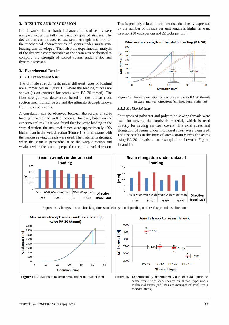
3.1.1 Unidirectional tests
The ultimate strength tests under different types of loading
are summarized in Figure 13, where the loading curves are
shown (as an example for seams with PA 30 thread). The
fiber strength was determined based on the known cross
section area, normal stress and the ultimate strength known
from the experiments.
A correlation can be observed between the results of static
loading in warp and weft directions. However, based on the
experimental results it was found that for static loading in the
warp direction, the maximal forces were approximately 10%
higher than in the weft direction (Figure 14). In all seams with
the various sewing threads were used. The material is strongest
when the seam is perpendicular to the warp direction and
weakest when the seam is perpendicular to the weft direction.
This is probably related to the fact that the density expressed
by the number of threads per unit length is higher in warp
direction (28 ends per cm and 22 picks per cm).
Figure 13. Force–elongation curves of seams with PA 30 threads
in warp and weft directions (unidirectional static test)
3.1.2 Multiaxial tests
Four types of polyester and polyamide sewing threads were
used for sewing the sandwich material, which is used
directly for sewing car seat covers. The axial stress and
elongation of seams under multiaxial stress were measured.
The test results in the form of stress-strain curves for seams
using PA 30 threads, as an example, are shown in Figures
15 and 16.
Figure 14. Changes in seam breaking forces and elongation depending on thread type and test direction
Figure 15. Axial stress to seam break under multiaxial load Figure 16. Experimentally determined value of axial stress to
seam break with dependency on thread type under
multiaxial stress (red lines are averages of axial stress
to seam break)
332 TEKSTİL ve KONFEKSİYON 29(4), 2019
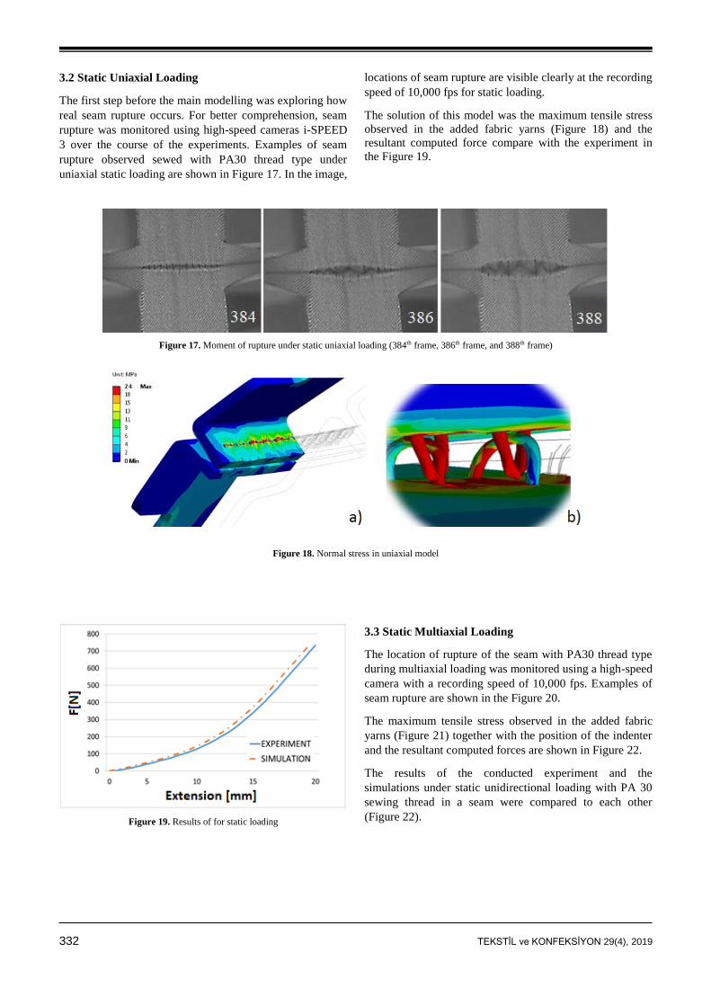
3.2 Static Uniaxial Loading
The first step before the main modelling was exploring how
real seam rupture occurs. For better comprehension, seam
rupture was monitored using high-speed cameras i-SPEED
3 over the course of the experiments. Examples of seam
rupture observed sewed with PA30 thread type under
uniaxial static loading are shown in Figure 17. In the image,
locations of seam rupture are visible clearly at the recording
speed of 10,000 fps for static loading.
The solution of this model was the maximum tensile stress
observed in the added fabric yarns (Figure 18) and the
resultant computed force compare with the experiment in
the Figure 19.
Figure 17. Moment of rupture under static uniaxial loading (384th frame, 386th frame, and 388th frame)
Figure 18. Normal stress in uniaxial model
Figure 19. Results of for static loading
3.3 Static Multiaxial Loading
The location of rupture of the seam with PA30 thread type
during multiaxial loading was monitored using a high-speed
camera with a recording speed of 10,000 fps. Examples of
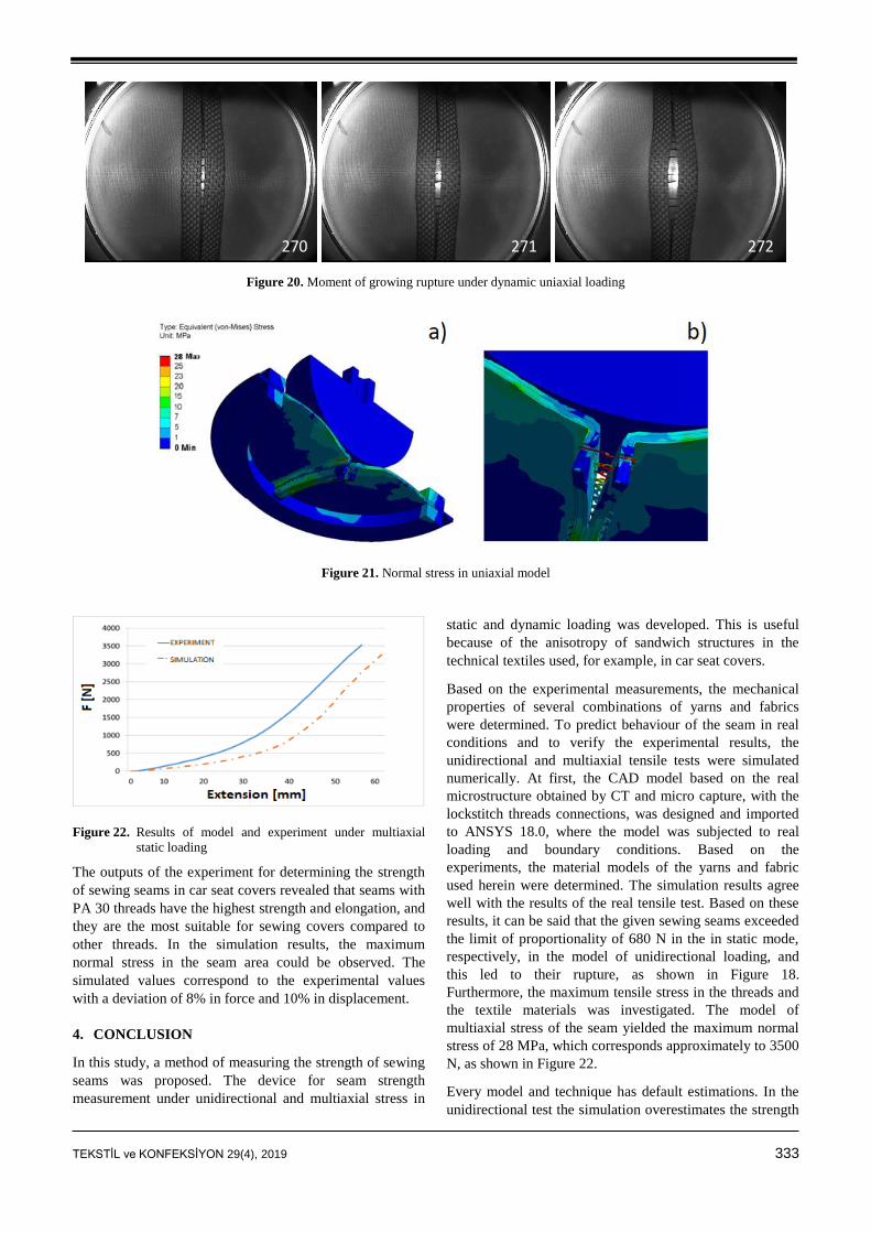
seam rupture are shown in the Figure 20.
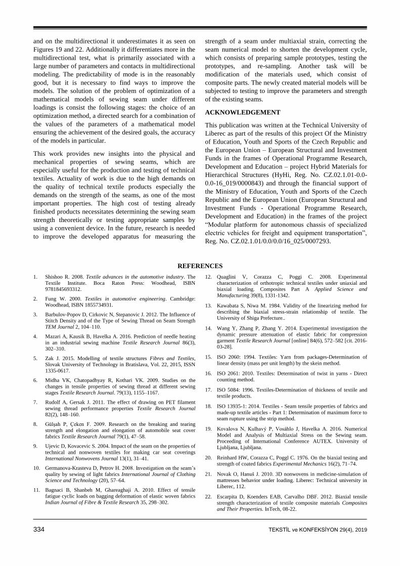
The maximum tensile stress observed in the added fabric
yarns (Figure 21) together with the position of the indenter
and the resultant computed forces are shown in Figure 22.
The results of the conducted experiment and the
simulations under static unidirectional loading with PA 30
sewing thread in a seam were compared to each other
(Figure 22).
TEKSTİL ve KONFEKSİYON 29(4), 2019 333
270 271 272
Figure 20. Moment of growing rupture under dynamic uniaxial loading
Figure 21. Normal stress in uniaxial model
Figure 22. Results of model and experiment under multiaxial
static loading
The outputs of the experiment for determining the strength
of sewing seams in car seat covers revealed that seams with
PA 30 threads have the highest strength and elongation, and
they are the most suitable for sewing covers compared to
other threads. In the simulation results, the maximum
normal stress in the seam area could be observed. The
simulated values correspond to the experimental values
with a deviation of 8% in force and 10% in displacement.
4. CONCLUSION
In this study, a method of measuring the strength of sewing
seams was proposed. The device for seam strength
measurement under unidirectional and multiaxial stress in
static and dynamic loading was developed. This is useful
because of the anisotropy of sandwich structures in the
technical textiles used, for example, in car seat covers.
Based on the experimental measurements, the mechanical
properties of several combinations of yarns and fabrics
were determined. To predict behaviour of the seam in real
conditions and to verify the experimental results, the
unidirectional and multiaxial tensile tests were simulated
numerically. At first, the CAD model based on the real
microstructure obtained by CT and micro capture, with the
lockstitch threads connections, was designed and imported
to ANSYS 18.0, where the model was subjected to real
loading and boundary conditions. Based on the
experiments, the material models of the yarns and fabric
used herein were determined. The simulation results agree
well with the results of the real tensile test. Based on these
results, it can be said that the given sewing seams exceeded
the limit of proportionality of 680 N in the in static mode,
respectively, in the model of unidirectional loading, and
this led to their rupture, as shown in Figure 18.
Furthermore, the maximum tensile stress in the threads and
the textile materials was investigated. The model of
multiaxial stress of the seam yielded the maximum normal
stress of 28 MPa, which corresponds approximately to 3500
N, as shown in Figure 22.
Every model and technique has default estimations. In the
unidirectional test the simulation overestimates the strength
334 TEKSTİL ve KONFEKSİYON 29(4), 2019
and on the multidirectional it underestimates it as seen on
Figures 19 and 22. Additionally it differentiates more in the
multidirectional test, what is primarily associated with a
large number of parameters and contacts in multidirectional
modeling. The predictability of mode is in the reasonably
good, but it is necessary to find ways to improve the
models. The solution of the problem of optimization of a
mathematical models of sewing seam under different
loadings is consist the following stages: the choice of an
optimization method, a directed search for a combination of
the values of the parameters of a mathematical model
ensuring the achievement of the desired goals, the accuracy
of the models in particular.
This work provides new insights into the physical and
mechanical properties of sewing seams, which are
especially useful for the production and testing of technical
textiles. Actuality of work is due to the high demands on
the quality of technical textile products especially the
demands on the strength of the seams, as one of the most
important properties. The high cost of testing already
finished products necessitates determining the sewing seam
strength theoretically or testing appropriate samples by
using a convenient device. In the future, research is needed
to improve the developed apparatus for measuring the
strength of a seam under multiaxial strain, correcting the
seam numerical model to shorten the development cycle,
which consists of preparing sample prototypes, testing the
prototypes, and re-sampling. Another task will be
modification of the materials used, which consist of
composite parts. The newly created material models will be
subjected to testing to improve the parameters and strength
of the existing seams.
ACKNOWLEDGEMENT
This publication was written at the Technical University of
Liberec as part of the results of this project Of the Ministry
of Education, Youth and Sports of the Czech Republic and
the European Union – European Structural and Investment
Funds in the frames of Operational Programme Research,
Development and Education – project Hybrid Materials for
Hierarchical Structures (HyHi, Reg. No. CZ.02.1.01-0.0-
0.0-16_019/0000843) and through the financial support of
the Ministry of Education, Youth and Sports of the Czech
Republic and the European Union (European Structural and
Investment Funds - Operational Programme Research,
Development and Education) in the frames of the project
“Modular platform for autonomous chassis of specialized
electric vehicles for freight and equipment transportation”,
Reg. No. CZ.02.1.01/0.0/0.0/16_025/0007293.
REFERENCES
1. Shishoo R. 2008. Textile advances in the automotive industry. The
Textile Institute. Boca Raton Press: Woodhead, ISBN 9781845693312.
2. Fung W. 2000. Textiles in automotive engineering. Cambridge: Woodhead, ISBN 1855734931.
3. Barbulov-Popov D, Cirkovic N, Stepanovic J. 2012. The Influence of Stitch Density and of the Type of Sewing Thread on Seam Strength
TEM Journal 2, 104–110.
4. Mazari A, Kausik B, Havelka A. 2016. Prediction of needle heating
in an industrial sewing machine Textile Research Journal 86(3), 302–310.
5. Zak J. 2015. Modelling of textile structures Fibres and Textiles, Slovak University of Technology in Bratislava, Vol. 22, 2015, ISSN
1335-0617.
6. Midha VK, Chatopadhyay R, Kothari VK. 2009. Studies on the
changes in tensile properties of sewing thread at different sewing
stages Textile Research Journal. 79(13), 1155–1167.
7. Rudolf A, Gersak J. 2011. The effect of drawing on PET filament
sewing thread performance properties Textile Research Journal 82(2), 148–160.
8. Gülşah P, Çeken F. 2009. Research on the breaking and tearing strength and elongation and elongation of automobile seat cover
fabrics Textile Research Journal 79(1), 47–58.
9. Ujevic D, Kovacevic S. 2004. Impact of the seam on the properties of
technical and nonwoven textiles for making car seat coverings
International Nonwovens Journal 13(1), 31–41.
10. Germanova-Krasteva D, Petrov H. 2008. Investigation on the seam’s
quality by sewing of light fabrics International Journal of Clothing Science and Technology (20), 57–64.
11. Bagnaci B, Shanbeh M, Ghareaghaji A. 2010. Effect of tensile fatigue cyclic loads on bagging deformation of elastic woven fabrics
Indian Journal of Fibre & Textile Research 35, 298–302.
12. Quaglini V, Corazza C, Poggi C. 2008. Experimental
characterization of orthotropic technical textiles under uniaxial and biaxial loading. Composites Part A Applied Science and
Manufacturing 39(8), 1331-1342.
13. Kawabata S, Niwa M. 1984. Validity of the linearizing method for
describing the biaxial stress-strain relationship of textile. The
University of Shiga Prefecture..
14. Wang Y, Zhang P, Zhang Y. 2014. Experimental investigation the dynamic pressure attenuation of elastic fabric for compression
garment Textile Research Journal [online] 84(6), 572–582 [cit. 2016-03-28].
15. ISO 2060: 1994. Textiles: Yarn from packages-Determination of
linear density (mass per unit length) by the skein method.
16. ISO 2061: 2010. Textiles: Determination of twist in yarns - Direct
counting method.
17. ISO 5084: 1996. Textiles-Determination of thickness of textile and textile products.
18. ISO 13935-1: 2014. Textiles - Seam tensile properties of fabrics and
made-up textile articles - Part 1: Determination of maximum force to seam rupture using the strip method.
19. Kovalova N, Kulhavý P, Vosáhlo J, Havelka A. 2016. Numerical
Model and Analysis of Multiaxial Stress on the Sewing seam. Proceeding of International Conference AUTEX. University of
Ljubljana, Ljubljana.
20. Reinhard HW, Corazza C, Poggl C. 1976. On the biaxial testing and strength of coated fabrics Experimental Mechanics 16(2), 71–74.
21. Novak O, Hanuš J. 2010. 3D nonwovens in medicine-simulation of
mattresses behavior under loading. Liberec: Technical university in Liberec, 112.
22. Escarpita D, Koenders EAB, Carvalho DBF. 2012. Biaxial tensile
strength characterization of textile composite materials Composites and Their Properties. InTech, 08-22.

TEKSTİL ve KONFEKSİYON 29(4), 2019 335
23. Mukhopadhyay SK., Jeffrey FL. 1999. Partridge automotive textiles.
The textile Institute, Oxford,
24. ISO 139: 2005. Textiles — Standard atmospheres for conditioning
and testing.
25. Kulhavy P, Kovalova N, Vosahlo J. 2015. Numerical model of the
static loading of a stitched seam in the composite cover of car seat
Applied Mechanics and Materials 827, Trans tech publication.
26. Matousek I. 2005. Computer modelling in the automated production
of molded glass. Technical University of Liberec: Liberec, 28s. ISBN 80-708-3988-0.
27. Zára J., Benes B. 2004. Modern computer graphics. Computer Press: Brno, 609 p. ISBN 80-251-0454-0.
28. Vosahlo J, Novak O, Petru M, Lepsik P. 2014. Experimental and numerical study of mechanical properties of artificial blood vessel,
EAN- 52nd International Conference. on Exp. Stress Analysis.
Marianske Lazne; Czech Republic, 175-176.
29. Madenci E, Guven I. 2006. The Finite Element Method and
Applications in Engineering Using ANSYS. Springer, ISBN-13: 978-
0387282893.
30. Talia M, Lankarani H, Talia JE. 1999. New experimental technique
for the study and analysis of solid particle erosion mechanisms Wear pp. 225-229, pp.1070–1077.
31. Jirasek M, Bazant Z. 2002. Inelastic analysis of structures, Wiley, ISBN 0-471-98716-6.
32. Zavarise G, Wriggers P, Schrefler BA. 1995. On augmented Lagrangian algorithms for thermomechanical contact problems with
friction International Journal for Numerical Methods in Engineering
38 (17), 2929–2949.