Embed Size (px)
Citation preview

420010307900
14.05.2010
BLU 15000.1 PR BLU 18000.1 PR
BRUCIATORI A GAS PROGRESSIVI PROGRESSIVE GAS BURNERSBRULEURS GAZ PROGRESSIVESQUEMADOR DE GAS PROGRESIVOSДУТЬЕВЫЕ ГАЗОВЫЕ ГОРЕЛКИ
IT
EN
FR
ES
RU

2
420010307900 BLU 15000.1 - 18000.1 PRIT
Indice
1 - Dati tecnici- Caratteristiche tecniche . . . . . . . . . . . . . . . . . . . . . . . . . . . . . . . . . . . . . . . . .p.3
- Campo di lavoro . . . . . . . . . . . . . . . . . . . . . . . . . . . . . . . . . . . . . . . . . . . . . .p.3
- Dimensioni di ingombro . . . . . . . . . . . . . . . . . . . . . . . . . . . . . . . . . . . . . . . . .p.3
2 - Installazione- Allacciamento elettrico . . . . . . . . . . . . . . . . . . . . . . . . . . . . . . . . . . . . . . . . .p.4
- Allacciamento gas . . . . . . . . . . . . . . . . . . . . . . . . . . . . . . . . . . . . . . . . . . . . .p.4
3 - Avviamento e regolazioni- Funzionamento del bruciatore . . . . . . . . . . . . . . . . . . . . . . . . . . . . . . . . . . . .p.4
- Regolazione della combustione . . . . . . . . . . . . . . . . . . . . . . . . . . . . . . . . . .p.4
- Funzionamento apparecchiatura di controllo . . . . . . . . . . . . . . . . . . . . . . . .p.5
- Regolazioni aria / gas . . . . . . . . . . . . . . . . . . . . . . . . . . . . . . . . . . . . . . . . . .p.5,6
- Regolazioni testa / pressostati . . . . . . . . . . . . . . . . . . . . . . . . . . . . . . . . . . .p.7
- Controllo sistema di rivelazione fiamma . . . . . . . . . . . . . . . . . . . . . . . . . . . .p.8
- Smontaggio testa di combustione . . . . . . . . . . . . . . . . . . . . . . . . . . . . . . . . .p.8
- Pannello di comando . . . . . . . . . . . . . . . . . . . . . . . . . . . . . . . . . . . . . . . . . . .p.9
4 - Manutenzione- Anomalie di funzionamento . . . . . . . . . . . . . . . . . . . . . . . . . . . . . . . . . . . . . .p.9

3
420010307900 BLU 15000.1 - 18000.1 PR IT
mbar
2000 3000 4000 5000 6000 7000 8000 9000 10000
10
12
14
16
1000
2000 30001000
18
20
22
11000
0
2
4
6
8
24
26
28
30
12000 kW13000
32
34
36
38
40
kcal/hx 10004000 5000 6000 7000 8000 9000 10000 11000 12000 13000 14000 15000 16000 17000
14000 15000 16000 17000 18000 19000
BLU 15000.1 PR
BLU
18000.1 PR
CARATTERISTICHE TECNICHE
CAMPO DI LAVORO
DIMENSIONI D’INGOMBRO
MODELLI BLU 15000.1 BLU 18000.1
Potenza termica max. kcal/h 12.931.000 14.655.000kW 15.000 17.000
Potenza termica min. kcal/h 3.181.000 3.448.270kW 3.690 4.000
Pressione Gas metano mbar 125÷700 175÷700Pressione GPL mbar 135÷700 190÷700Tensione di alim.trifase 50 Hz V 230/400 230/400Motore kW 45 55Giri/minuto del motore Nº 2.800 2.800Combustibile : Gas Naturale (P.C.I. 8.570 kcal/Nm3), GPL (P.C.I. 22.260 kcal/Nm3)
L
M 20
I
E D
GH
1150
ACB
F
N
O
Dimensione (mm)
D = Testa corsaD1= Testa lunga
MODELLI A B C D D1 E F G H I L M N OBlu 15000.1 1530 810 720 590 - 1860 550 1170 530 620 620 M20 210 320Blu 18000.1 1580 860 720 590 - 1860 550 1170 530 620 620 M20 210 320
Pre
ssio
ne in
cam
era
di c
ombu
stio
ne
Potenza

4
420010307900 BLU 15000.1 - 18000.1 PRIT
ALLACCIAMENTO ALLA LINEA GASAllacciato il bruciatore alla tubazione del gas è necessario assicurarsi che quest’ultima sia a tenuta perfetta. Assicurarsipure che il camino non sia ostruito. Aperto il rubinetto del gas sfiatare con prudenza la tubazione attraverso l’appositapresa di pressione e quindi controllare il valore della pressione con un manometro idoneo. Dare tensione all’impianto eregolare i termostati alla temperatura desiderata. Alla chiusura dei termostati, il dispositivo di controllo fughe gas effet-tua una prova di tenuta delle valvole; Al termine della prova il bruciatore riceve il consenso per effettuare il ciclo diavviamento.
AVVIAMENTO DEL BRUCIATOREPrima di accendere il bruciatore, assicurarsi che sia montato correttamente. Controllare i collegamenti elettrici secondo idiagrammi e le tubazioni dell’impianto. Prima del collegamento elettrico assicurarsi che il voltaggio corrisponda ai datiindicati nella targhetta caratteristiche.Il diagramma del collegamento elettrico e il ciclo di avviamento sono illustratiseparatamente. Per collegare l’apparecchiatura al bruciatore, vedere lo schema. Prestare particolarmente attenzione alcollegamento del neutro e della fase: non scambiarli mai. Controllare il collegamento terra dell’impianto. Nei motoritrifase controllare il senso di rotazione del motore (vedere freccia). Sfiatare l’aria e le impurità della tubazione del gas.Controllare che la pressione del gas sia nei limiti indicati nella targhetta. Questo controllo deve essere effettuato con unmanometro gas nell’apposita presa di pressione prevista sul bruciatore. Si avvia il motore ed inizia la preventilazione. Ilmotoriduttore porta la serranda dell’aria alla massima apertura in circa 30 secondi. Quando il motoriduttore é comple-tamente aperto, un segnale all’apparecchiatura elettronica di controllo avvia un ciclo di preventilazione di circa 66secondi. Alla fine di questa preventilazione, il motoriduttore porta la serranda in bassa fiamma permettendo l’accensio-ne del bruciatore alla minima portata. Contemporaneamente il trasformatore di accensione viene alimentato e dopo tresecondi (36 sec.LFL1.133)(pre-accensione) viene alimentata anche la valvola pilota. Due secondi dopo l’apertura dellavalvola pilota, il trasformatore é escluso dal circuito. In caso di mancanza di accensione il bruciatore va in blocco entrodue secondi. Dopo 6 sec. apre la valvola di lavoro. A questo punto la valvola a farfalla regola la portata del gas nella testadi combustione.Il bruciatore si trova acceso alla minima potenza (circa 30% della massima potenza). Lo strumentomodulatore farà aprire il servomotore alla massima potenza o lo fermerà alla potenza intermedia richiesta dall’impianto.L’apertura del servomotore farà aprire gas ed aria in modo proporzionale per avere sempre a tutte le portate (30%-100%) una combustione ottimale. Al termine del funzionamento il servomotore si porta in posizione di chiusura.
CONSIGLI IMPORTANTITutti gli organi regolabili devono essere fissati dall’installatore dopo le regolazioni. Ad ogni regolazione controllate lacombustione al camino. I valori di CO2 devono essere circa 9,7 (G20) 9,6 (G25) 11,7 (I3B) 11,7 (I3P) ed il CO infe-riore a 75 ppm.
ALLACCIAMENTO ELETTRICOTutti i bruciatori sono collaudati a 400 V 50 Hz trifase per i motori e 230V 50 Hz monofase con neutro per gli ausilia-ri. Se fosse necessario alimentare il bruciatore a 230 V 50 Hz trifase senza neutro, eseguire le modifiche necessarie rife-rendosi allo specifico schema elettrico del bruciatore e controllare che il relé termico sia entro il campo di assorbimentodel motore. Accertare inoltre il corretto senso di rotazione del motore del ventilatore.
REGOLAZIONE DELLA COMBUSTIONEATTENZIONE : per ottenere una corretta regolazione della combustione e della portata termica occorre effettuare l'analisi dei fumi, ser-vendosi degli appositi strumenti. La regolazione della combustione e della portata termica va eseguita contemporaneamente ad una analisidei prodotti della combustione, assicurandosi che i valori riscontrati siano corretti, e, in ogni caso, rispondenti alle normative di sicurezzavigenti. A tal proposito vedere la tabella e la figura sottostanti. TALE OPERAZIONE DEVE ESSERE ESEGUITA DA PERSONALEPROFESSIONALMENTE QUALIFICATO ED AUTORIZZATO DALLA ECOFLAM BRUCIATORI SPA .
NB-TUTTI GLI ORGANI DI SICUREZZA (PRESSOSTATO ARIA, PRESSOSTATO GAS DI MINIMA, ELETTROVAL-VOLE GAS E STABILIZZATORE DI PRESSIONE) DOVRANNO ESSERE OPPORTUNAMENTE SIGILLATI DOPOLA TARATURA E MESSA IN FUNZIONE DEI BRUCIATORI DA PARTE DEL PERSONALE QUALIFICATO E AUTO-RIZZATO ECOFLAM BRUCIATORI SPA.

5
420010307900 BLU 15000.1 - 18000.1 PR IT
L’apparecchiatura controllo fiamma fapartire il ventilatore del bruciatore pereffettuare il prelavaggio della camera dicombustione, controllando la presionedell’aria di ventilazione tramite il pres-sostato aria. Al termine della preventila-zione entra in funzione il trasformatoredi accensione generando una scintillatra gli elettrodi e contemporaneamente si aprono le valvole del gas (valvole gas di sicurezza VS e valvola di lavoro VL).La sicurezza totale in caso di mancata accensione o di spegnimento accidentale viene affidata a una sonda di rivelazioneche interviene mandando in blocco l’apparecchiatura entro il tempo di sicurezza. Nel caso di mancanza di gas o di uncalo notevole di pressione il pressostato gas di minima provvede ad interrompere il funzionamento del bruciatore.
Rif.�descrizione������������������������ �
t1 tempo di attesa della conferma della pressione dell'aria 8"
t2 tempo di preventilazione 66" t3 tempo di sicurezza 2" t4 tempo di preaccensione 4" t5 tempo per il consenso di funzionam.
alla minima potenza della valvola di lavoro del combustibile 10"" t6 tempo per il consenso di funzionam.
alla massima potenza della valvola dilavoro del combustibile 10"
durata
CICLO DI FUNZIONAMENTO DELL’APPARECCHIATURA LANDIS & STAEFA MOD. LFL1.622-1.333
Rivelazionedi fiamma
Spia di blocco
Valvola gas
Serranda aria
Farfalla gas
Trasformatoredi accensione
Pressostato aria
Motore ventilatore
Pressostato gas
0min
100%
t1 t2
t4
t3
t6t5
Ciclo di funzionamento normaleCiclo di funzionamento�
in mancanza di fiamma all'accensionet1 t2
t4
t3
Consensomin./max. potenza
SERVOCOMANDO ARIA LANDIS & STAEFA SQM 50.481A2 Togliere il coperchio per accedere alle camme di regolazione. Lo spostamento delle camme va effettuato con l’ausiliodell’apposita chiavetta in dotazione. Descrizione :
I - Camma di regolazione serranda aria in alta fiamma.II - Camma di regolazione serranda aria per chiusura totale.III - Camma di regolazione serranda aria per fiamma accensione.IV - Camma di regolazione serranda aria in bassa fiamma.V - Camma non usataVI - Camma non usataVII - Camma non usataVIII- Camma non usata
Camma VIII non usata
REGOLAZIONE DELLA COMBUSTIONEATTENZIONE: Ai fini di una corretta regolazione della combustione e della portata termica, queste vanno eseguitecontemporaneamente ad una analisi dei fumi, da effettuarsi con strumenti appositi, controllamndo che i valori riscon-trati siano corretti e rispondenti alle normative di sicurezza in vigore. Le operazioni di rgolazione debbono essere effet-tuate da personale qualificato ed autorizzato dalla Ecoflam bruciatori S.p.A.
66”(36”)

6
420010307900 BLU 15000.1 - 18000.1 PRIT
REGOLAZIONE DELLA PORTATA ARIA E GAS
REGOLAZIONE DELLA POTENZA MINIMA DEL GASPosizionare il commutatore che si trova sulla mostrina in posizione 2 e agire come segue:Per regolare la portata minimo del gas agire con la chiave a brugola sulla vite della camma e modificare l’angolo dellaserranda gas della valvola a farfalla.
REGOLAZIONE DELLA POTENZA MASSIMA DEL GASPosizionare il commutatore che si trova sulla mostrina in posizione 1 e agire come segue:Per regolare la portata massimo del gas agire sull’elettrovalvola di regolazione fino a ottenere il valore corretto per la cal-daia.
REGOLAZIONE DELLA PORTATA MASSIMA DELL’ARIA Svitare la vite di fissaggio dell’asta e mettere la stessa nella posizione corretta.Alla fine della regolazione richiudere la vite dell’asta.
REGOLAZIONE DELLA PORTATA INTERMEDIA DEL GASAzionare il servomotore con il commutatore (aperto/chiuso) e posizionarlo nella posizione 0 per fermarlo. Per la regola-zione, agire come segue. Ripetere i passaggi per gli altri punti delle camme.Regolazione della portata intermediaria del gas (vedere immagine 3):Con una chiave a brugola modificare la posizione della lamina guida della camma, chiudendo la portata aumenta,aprendo la portata diminuisce.
CALCOLO PORTATA BRUCIATOREPer calcolare la portata in kW del bruciatore, procedere nel modo seguente :Controllare al contatore la portata in litri del gas e il tempo in secondi della lettura.
Procedere al calcolo secondo la formula : e x f = kWsec
e = Litri gassec = Tempo in secondi G20 = 34,02G25 = 29,25G30 = 116G31 = 88
f
COMMUTATORE
0
AUTO
0 = bloccaggio degli apparati per il funzionamento in una posizione intermadia = funzionamento alla massima potenza = funzionamento alla minima potenza AUTO = funzionamento automatico
Part. 2+
+
--
+
--
Part. 3
operating elements locked in an inter-mediate positionoperation on maximum capacity operation on minimum capacity automatic operation
SELECTOR

7
420010307900 BLU 15000.1 - 18000.1 PR IT
POSIZIONE DEGLI ELETTRODI
TARATURA DEL PRESSOSTATO GAS DI MINIMA PRESSIONESvitare le viti I e L e togliere il coperchio M. posizionare il regolatore N ad un valore pari al 60%della pressione nominale di alimentazione gas (es.: per gas metano press. nominale =20 mbar;regolatore posizionato al valore 12 mbar; per G.P.L. pressione nominaleG30-G31 30/37mbar regolatore posizionato al valore di 18 mbar). - rimontare il coperchio M e riavvitare leviti I e L.
REGOLAZIONE DEL PRESSOSTATO ARIASvitare le viti A e B e rimuovere il coperchio C. - Regolare il pressostato aria al minimo ruotan-do il regolatore D in posizione 1. - Avviare il bruciatore ed impostare il funzionamento in 1° sta-dio (1 fiamma) verificando che la combustione sia corretta. Servendosi di un cartoncino,ostruire progressivamente il condotto di aspirazione aria, sino ad ottenere un aumento delvalore della CO2 pari al 0,5÷0,8% oppure, se si dispone di un manometro collegato allapresa di pressione E, sino ad ottenere una diminuzione di pressione di 1 mbar (10 mmC.A.). Aumentare progressivamente il valore di taratura del pressostato sino a causare lospegnimento in blocco del bruciatore. Rimuovere l’ostruzione dal condotto, rimontare ilcoprechio C e ripristinare il funzionamento del bruciatore agendo sul pulsante di riarmo del blocco dell’appa-recchiatura.NB: La pressione misurata alla presa E deve rientrare nel campo di lavoro del pressostato. Se così non fosse, allentareil dado di bloccaggio della vite F ed agire gradualmente sulla stessa: in senso orario per ridurre la pressione; in sensoantiorario per aumentarla. Al termine della regolazione fissare il dado.
2,55
10 15
50
25
35
30
4045
20
0,4
0,6 0,9
3,0
1,5
2,1
1,8
2,42,7
1,2
I
L
MN
A
B
CD
E
F
GH
REGOLAZIONE TESTA DI COMBUSTIONE
50 mm
5 mm
10 mm
elettrodoaccensione
elettrodorivelazione 20
mm

8
420010307900 BLU 15000.1 - 18000.1 PRIT
Il controllo della corrente di ionizzazione si effettuainserendo un microamperometro con fondo scaladi 50 µA (corrente continua) in serie all'elettrododi rivelazione. Un errato posizionamento dell'elet-trodo può comportare una riduzione della correntedi ionizzazione e determinare un arresto di sicurez-za del bruciatore dovuto a mancanza di rivelazionedi fiamma. In tal caso verificare il corretto posizio-namento dell'elettrodo, il collegamento elettrico di questo e la messa a terra del bruciatore. Normalmente il valore dellacorrente di ionizzazione è >20 µA.
24
min. 6 μA
LANDIS LFL1.622Microamperometro fondo scala 50 μA
CONTROLLO SISTEMA DI RILEVAZIONE FIAMMA
SMONTAGGIO TESTA DI COMBUSTIONEATTENZIONE !
SMONTAGGIO BOCCAGLIO

9
420010307900 BLU 15000.1 - 18000.1 PR IT
ANOMALIE DI FUNZIONAMENTOCONTROLLO ANNUALE
Il controllo periodico del bruciatore (testa di combustione, elettrodi,ecc.) deve essere effettuato da personale autorizzatouna o due volte all’anno a secondo dell’utilizzo. Prima di procedere al controllo per la manutenzione del bruciatore èconsigliabile verificare lo stato generale del bruciatore e seguire le seguenti operazioni : - Togliere tensione al bruciatore(togliere la spina). - Chiudere il rubinetto di intercettazione gas. - Togliere il coperchio del bruciatore, pulire la ventolae l’aspirazione dell’aria. - Pulire la testa di combustione e controllare la posizione degli elettrodi. - Rimontare i pezzi. -Verificare la tenuta dei raccordi gas. - Verificare il camino. - Far ripartire il bruciatore. - Controllare i parametri dellacombustione.
PRIMA DI OGNI INTERVENTO CONTROLLARE :- Che ci sia corrente elettrica nell’impianto e il bruciatore collegato. - Che la pressione del gas sia corretta e il rubinetto di intercettazione del gas aperto. - Che i sistemi di controllo siano regolarmente collegati. Se tutte queste condizioni sono soddisfatte , far partire il bruciatore premendo il pulsante di sblocco. Controllare il ciclo del bruciatore.
IL BRUCIATORE NON SI AVVIA : - Controllare l’interruttore, i termostati, il motore, pressione gas.
IL BRUCIATORE EFFETTUA LA PREVENTILAZIONE E AL TERMINE DEL CICLO VA IN BLOCCO :- Controllare la pressione dell’aria e la ventola. - Controllare il pressostato aria.
IL BRUCIATORE EFFETTUA LA PREVENTILAZIONE E NON ACCENDE :- Verificare il montaggio e la posizione degli elettrodi. - Verificare il cavo di accensione. - Verificare il trasformatore di accensione. - Verificare l’apparecchiatura di sicurezza.
IL BRUCIATORE SI ACCENDE E DOPO IL TEMPO DI SICUREZZA VA IN BLOCCO : - Controllare fase e neutro che siano collegati correttamente. - Controllare l’elettrovalvole del gas. - Controllare la posizione dell’elettrodo di rivelazione e la sua connessione. - Controllare l’elettrodo di rivelazione. - Controllare l’apparecchiatura di sicurezza.
IL BRUCIATORE SI ACCENDE E DOPO QUALCHE MINUTO DI FUNZIONAMENTO VA IN BLOCCO :- Controllare il regolatore di pressione e il filtro gas. - Controllare la pressione del gas con un manometro. - Controllare il valore di rivelazione (min 6 µA).
DESCRIZIONE DEL PANNELLO DI COMANDO DEI BRUCIATORI
1 - fusibile2 - lampada di blocco termico3 - lampada di funzionamento gasolio4 - commutatore : 0 bloccaggio degli apparati per il funzionamento in una posizione intermedia
funzionamento alla massima potenza
funzionamento alla minima potenza
AUTO funzionamento automatico
5 - interruttore I / O6 - pulsante di sblocco
43
5
2 1
0
AUTO
0I
GAS
6

10
420010307900 BLU 15000.1 - 18000.1 PR
ENIndex
1 - Technical data- Technical data . . . . . . . . . . . . . . . . . . . . . . . . . . . . . . . . . . . . . . . . . . . . . . . .p.11
- Working fields . . . . . . . . . . . . . . . . . . . . . . . . . . . . . . . . . . . . . . . . . . . . . . . .p.11
- Overal dimensions . . . . . . . . . . . . . . . . . . . . . . . . . . . . . . . . . . . . . . . . . . . .p.11
2 - Installation- Electrical connections . . . . . . . . . . . . . . . . . . . . . . . . . . . . . . . . . . . . . . . . . .p.12
- Gas connection . . . . . . . . . . . . . . . . . . . . . . . . . . . . . . . . . . . . . . . . . . . . . . .p.12
3 - Starter and regulations- Working of the burner . . . . . . . . . . . . . . . . . . . . . . . . . . . . . . . . . . . . . . . . . .p.12
- Adjusting combustion process . . . . . . . . . . . . . . . . . . . . . . . . . . . . . . . . . . .p.12
- Control box up-cycle . . . . . . . . . . . . . . . . . . . . . . . . . . . . . . . . . . . . . . . . . . .p.13
- Adjusting air/gas . . . . . . . . . . . . . . . . . . . . . . . . . . . . . . . . . . . . . . . . . . . . . .p.13,14
- Adjusting combustion head/pressure switch . . . . . . . . . . . . . . . . . . . . . . . . .p.15
- Ionization current . . . . . . . . . . . . . . . . . . . . . . . . . . . . . . . . . . . . . . . . . . . . . .p.16
- Firing head disassembly . . . . . . . . . . . . . . . . . . . . . . . . . . . . . . . . . . . . . . . .p.16
- Control pannel . . . . . . . . . . . . . . . . . . . . . . . . . . . . . . . . . . . . . . . . . . . . . . . .p.17
4 - Maintenance- Troubleshooting . . . . . . . . . . . . . . . . . . . . . . . . . . . . . . . . . . . . . . . . . . . . . .p.17

11
420010307900 BLU 15000.1 - 18000.1 PR
EN
mbar
2000 3000 4000 5000 6000 7000 8000 9000 10000
10
12
14
16
1000
2000 30001000
18
20
22
11000
0
2
4
6
8
24
26
28
30
12000 kW13000
32
34
36
38
40
kcal/hx 10004000 5000 6000 7000 8000 9000 10000 11000 12000 13000 14000 15000 16000 17000
14000 15000 16000 17000 18000 19000
BLU 15000.1 PR
BLU
18000.1 PR
TECHNICAL DATA
WORKING FIELDS
OVERALL DIMENSIONS
MODELS BLU 15000.1 BLU 18000.1
Thermal power max. kcal/h 12.931.000 14.655.000kW 15.000 17.000
Thermal power min. kcal/h 3.181.000 3.448.270kW 3.690 4.000
Gas pressure Natural gas mbar 125÷700 175÷700Gas pressure LPG mbar 135÷700 190÷700Voltage 50 Hz V 230/400 230/400Motor kW 45 55Rpm Nº 2.800 2.800Fuel : Natural gas = 35,9 Mj / Nm3 = 8.600 kcal / Nm3 L.P.G. 22.260 kcal/Nm3
L
M 20
I
E D
GH
1150
ACB
F
N
O
Dimensions (mm)
D = Short headD1= Long head
MODELS A B C D D1 E F G H I L M N OBlu 15000.1 1530 810 720 590 - 1860 550 1170 530 620 620 M20 210 320Blu 18000.1 1580 860 720 590 - 1860 550 1170 530 620 620 M20 210 320
com
bust
ion
cham
ber
pres
sure
capacity

12
420010307900 BLU 15000.1 - 18000.1 PR
EN
CONNECTION TO THE GAS PIPELINE Once connected the burner to the gas pipeline, it is necessary to control that this last is perfectly sealed. Also verify thatthe chimney is not obstructed. Open the gas cock and carefully bleed the piping through the pressure gauge connector,then check the pressure value trough a suitable gauge. Power on the system and adjust the thermostats to the desiredtemperature. When thermostats close, the sealing control device runs a seal test of valves; at the end of the test the bur-ner will be enabled to run the start-up sequence.
BURNER START-UPBefore starting the burner, make sure it is mounted correctly. Then check connections are correct according to the dia-gram and piping is appropriate to the system. Before connecting the burner to the electricity supply, make sure voltagecorresponds to burner plate data. The connection diagram and start-up cycle are shown separately. For wiring fromcontrol box to burner, see the enclosed connection diagram. Pay particular attention to neutral and phase connections :never exchange them!. Vent air and impurities of gas pipe. Check gas pressure conforms to the limits stated on the bur-ner plate when connecting a master gauge to the test port provided on the burner. Blower motor starts and pre-purgingbegins. Since pre-purging has to be carried out with the max. air delivery, the burner control circuit turns the air dam-per to the max. delivery position by the air servocontrol in approximately 30 seconds time. When the servocontrol isfully open, a signal to the electronic control unit starts the 66 seconds (36 sec.LFL1.133) pre-purge cycle. At the end ofthe prepurging time, the air servocontrol gets to the Low Flame position so that burner ignition is ensured at min. out-put. Simultaneously the ignition transformer receives voltage and after 3 seconds (pre-ignition) opens the pilot gasvalve. Fuel flows to the combustion head and ignites. Two seconds after pilot gas valves have opened, the ignition tran-sformer is excluded from the circuit. In case of no ignition the burner goes to lock-out within two seconds. After 6 sec.open the working gas valve, governed by the gas firing butterfly valve.Now the burner is operating at the min. firingrate (about 30% of the max. firing rate). The air servocontrol runs at the Low Flame position and in case the tempera-ture control has to be set at the max. output it goes to a fully open position of air damper and butterfly valve. Duringthe burner-off periods the air damper closes up fully.
ELECTRICAL CONNECTIONSAll burners factory tested at 400 V 50 Hz three-phase for motors and 230 V 50 Hz monophase with neutral for auxi-liary equipment. If mains supply is 230 V 50 Hz threephase withuot neutral, change position of connectors on burneras in fig. Protect burner supply line with safety fuses and any other devices required by safety standards obtaining in thecountry in question.
ADJUSTING THE COMBUSTION PROCESSIMPORTANT: to obtain the right adjustment of the combustion and thermal capacity it is important to analyze the reducts ofcombustion with the aid of suitable instruments. The combustion and thermal capacity adjustment is done simultaneously,together with the analysis of the products of combustion, making sure that the measured values are suitable and that they complywith current safety standards. On this matter, please refer to the table and figure below.THESE OPERATIONS MUST BE DONE BY PROFESSIONALLY-QUALIFIED TECHNICIANS.

13
420010307900 BLU 15000.1 - 18000.1 PR
EN
LANDIS & STAEFA SQM 50.481A2 AIR DAMPER MOTORRemove cover to gain access to the adjusting cams.The cams are to be adjusted through the suitable key provided for.Description:
I - Limit switch for air damper “High Flame” position adjusting.II - Limit switch for air damper position at burner’s shut down.III - Limit switch for air damper position at burner’s start up.IV - Limit switch for air damper “Low Flame” position adjusting.V - Not used camVI - Not used camVII - Not used camVIII - Not used cam
Cam VIII is never used
The control box starts the burnerfan, to carry out the prepurgingof the combustion chamber, andcheks the vent air pressure throu-gh the air pressure switch. At theend of prepurging, the ignitiontransformer cuts-in and generatesa spark between the electrodes. At
the same time the two gas valves open (Vs safety valve and Vl Low flame working valve). The total safety, in case ofmissed ignition or casual burner's flame-out, is granted by a ionisation probe which cuts-in and sets the burner shut-down within the safety time. In case of gas lack or a major pressure drop, the minimum air pressure switch shuts downthe burner.
LANDIS & STAEFA, Model LFL1.622-1.333 OPERATING CYCLERef. Descriptiont1 Duration Waiting time for confirmationt2 of air pressuret3 Preventilation timet4 Safety timet5 Pressurizing time
Time for enabling operation of the main gas valve on minimum capacity
t6 Time for enabling operation of the main gas valve on maximum capacity
Duration
8”66”(36”)
2”4”
10”
10”
Rivelazionedi fiamma
Spia di blocco
Valvola gas
Serranda aria
Farfalla gas
Trasformatoredi accensione
Pressostato aria
Motore ventilatore
Pressostato gas
0min
100%
t1 t2
t4
t3
t6t5
Ciclo di funzionamento normaleCiclo di funzionamento�
in mancanza di fiamma all'accensionet1 t2
t4
t3
Consensomin./max. potenza
Gas manostat
Fan motor
Air Switch
Ignition transformer
Gas valve
Min/max capacity enabling device
Air damper
Gas damper
Flame detector
Cut-out pilot lamp
Normal operating cycleOperating cycle in the event of
ignition failureNormal operating cycle
COMBUSTION ADJUSTMENT WARNING: In order to have a correct combustion and thermal output adjustments, these must be carried out togetherwith a combustion analysis, to be executed through suitable devices, taking care that the values are the correct ones andare in accordance with the local safety regulations. The adjustments must be carried out by qualified and skilled techni-cians authorised by Ecoflam Bruciatori S.p.A.

14
420010307900 BLU 15000.1 - 18000.1 PR
ENAIR ADJUSTMENT
ADJUSTING THE MINIMUM CAPACITY OF THE BURNER – AIR and GASPosition the selector placed on the control panel on position 2 and proceed as follows: Adjust the minimum gas flow rate using a suitable wrench, turn the butterfly valve until you reach the correct gas flow,as established by analyzing the combustion process.
ADJUSTING THE MAXIMUM CAPACITY OF THE GASPosition the selector, situated on the control panel, on position 1 and proceed as follows:Adjusting the maximum gas flow rate (see figure on solenoid valve adjustments) or adjust the gas pressure in the gover-nor.
ADJUSTING THE MAXIMUM AIR FLOW RATE Adjusting the maximum air flow rate (see figure, detail 2). Loosen the nut holding the air damper transmission rod;The correct air flow as established by analyzing the combustion process.
ADJUSTING THE INTERMEDIATE BURNER CAPACITY Using the selector, start the servomotor (closing or opening) and position on 0 to stop the stroke; the adjustment ismade as outlined below. Repeat the operation for the other cam points.Adjustment the intermediate gas flow rates (see figure, detail 3): - using a suitable Allen wrench, change the position ofthe cam guide blade; if you screw it down, the flow rate is reduced; if you unscrew it, the flow rate increases.
CALCULATING THE BURNER CAPACITYTo calculate the burner's capacity in kW, proceed as follows: Check the gas flow rate (in liters) onthe counter and the time of the reading in seconds.
Proceed with the calculation using the following : e x f = kWsec
e = Litres gassec = Time in secondG20 = 34,02G30 = 116G31 = 88
f
COMMUTATORE
0
AUTO
0 = bloccaggio degli apparati per il funzionamento in una posizione intermadia = funzionamento alla massima potenza = funzionamento alla minima potenza AUTO = funzionamento automatico
Part. 2+
+
--
+
--
Part. 3
operating elements locked in an inter-mediate positionoperation on maximum capacity operation on minimum capacity automatic operation
SELECTOR

15
420010307900 BLU 15000.1 - 18000.1 PR
EN
ADJUSTMENT OF GAS MINIMUM PRESSURE SWITCHUnscrew off and remove cover M. - Set regulator N to a value equal to 60% of gas nominal feed pressure(i.e. for nat. gas nom. pressure = 20 mbar, set regulator to a value of 12 mbar; for L.P.G. nom.pressure of G30/G31- 30/37 mbar, set regulator to a value of 18 mbar).Screw up cover M
ADJUSTMENT OF THE AIR PRESSURE SWITCHUnscrew screws A and B and remove cover C.- Set the pressure switch to the minimum byturning regulator D to position 1. - Start the burner and keep in low flame running, while checking that combustion is cor-rect. Through a small cardboard, progressively obstruct the air intake until to obtain a CO2 increase of0,5÷0,8% or else, if a pressure gauge is available, connected to pressure port E, until reaching apressure drop of 1 mbar (10 mm of W.G.). - Slowly increase the adjustment value of the airpressure switch until to have the burner lockout. Remove the obstruction from the air intake,screw on the cover C and start the burner by pressing the control box rearm button.
Note: The pressure measured at pressure port E must be within the limits of the pressureswitch working range. If not, loose the locking nut of screw F and gradually turn the same:clockwise to reduce the pressure; counterclockwise to increase. At the end tighten the locking nut.
2,55
10 15
50
25
35
30
4045
20
0,4
0,6 0,9
3,0
1,5
2,1
1,8
2,42,7
1,2
I
L
MN
A
B
CD
E
F
GH
FIRING HEAD SETTING
IGNITION END IONIZATION ELECTRODES
50 mm
5 mm
10 mm
elettrodoaccensione
elettrodorivelazione 20
mm
Ignition Electrode
Ionization Probe

16
420010307900 BLU 15000.1 - 18000.1 PR
EN
The ionization current is checked by inserting amicroammeter with an end of scale of 50 µA (d.c.)in series with the ionization probe. A faulty position of the electrode can lead to areduction in the ionization current and cause asafety cut-out of the burner due to a flame detec-tion failure. In this case, check the position of theelectrode, its electric connection and the earthingof the burner. The ionization current is normally > 20 µA.
24
min. 6 μA
LANDIS LFL1.622Microamperometro fondo scala 50 μA
IONIZATION CURRENT
FIRING HEAD DISASSEMBLYWARNING !
REMOVING THE BLAST TUBE
Microammeter50 μA end of scale

17
420010307900 BLU 15000.1 - 18000.1 PR
ENDESCRIPTION OF THE CONTROL PANEL OF THE BURNER
1 - Fuse2 - Termal lock-out lamp3 - Working lamp4 - Selector : 0 Loking of devoices for operating at intermediate outputs
Operation at max. output
Operation at min. output
AUTO Automatic operation
5 - Main switch I / O6 - Lockout disable push button7 - Modulating unit RWF 40
43
5
2 1
0
AUTO
0I
GAS
6
TROUBLESHOOTINGANNUAL CHECKThe burner (combustion head, electrodes, etc.) must be checked regularly by an authorized technician,once or twice a year, depending on how much it is used. Before proceeding withe the maintenance check-up on the burner, it is advisable to check the general condition of the burner and take the following steps:Disconnect the burner (remove the plug). - Close the gas shut-off cock. - Remove the cover from the burner, clean the fan and air intake. - Clean the combustion head and check the position of the electrodes. - Re-install the parts. - Check the seal on the gas connectors. - Check the state of the flue. - Start the burner. - Check the combustion parameters
BEFORE TAKING ANY ACTION, CHECK:- that there is power in the circit and the burner is connected; - that the gas pressure is right and the gas shut-off cock is open; - that the control systems are properly connected. If all these conditions have been satisfied, start the bur-ner by pressing the reset button. Check the burner cycle.
IF THE BURNER FAILS TO START:check the switch, the thermostats, the motor and the gas pressure.
IF THE BURNER PROCEEDS WITH PREVENTILATION BUT CUTS OUT AT THE END OF THE CYCLE:check the air pressure and the fan. Check the air pressure switch.
IF THE BURNER PROCEEDS WITH PREVENTILATION BUT DOES NOT LIGHT:check the installation and position of the electrodes. Check the ignition cable. Check the ignition transformer. Check the safety device.
IF THE BURNER LIGHTS BUT CUTS OUT AFTER THE SAFETY INTERVAL: check that the phase and neutral wires are connected correctly. Check the gas solenoid valve. Check the position and connection of the detector electrode. Check the detector electrode. Check the safety device.
IF THE BURNER LIGHTS BUT CUTS OUT AFTER OPERATING FOR A FEW MINUTES:check the pressure regulator and gas filter. Check the gas pressure with a pressure gauge. Check the detec-tor value (at least 6 µA).

18
420010307900 BLU 15000.1 - 18000.1 PR
FRIndex
1 - Caracteristiques techniques- Caracteristiques techniques . . . . . . . . . . . . . . . . . . . . . . . . . . . . . . . . . . . . .p.19
- Plage de travail . . . . . . . . . . . . . . . . . . . . . . . . . . . . . . . . . . . . . . . . . . . . . . .p.19
- Dimensions dʼencombrement . . . . . . . . . . . . . . . . . . . . . . . . . . . . . . . . . . . .p.19
2 - Installation- Connexion electrique . . . . . . . . . . . . . . . . . . . . . . . . . . . . . . . . . . . . . . . . . .p.20
- Connexion au reseau gaz . . . . . . . . . . . . . . . . . . . . . . . . . . . . . . . . . . . . . . .p.20
3 - Démarreur et règlements- Demarrage du brûleur . . . . . . . . . . . . . . . . . . . . . . . . . . . . . . . . . . . . . . . . . .p.20
- Reglage de la combustion . . . . . . . . . . . . . . . . . . . . . . . . . . . . . . . . . . . . . . .p.20
- Cycle de fonctionnement de coffret de securite . . . . . . . . . . . . . . . . . . . . . .p.21
- Reglage air / gaz . . . . . . . . . . . . . . . . . . . . . . . . . . . . . . . . . . . . . . . . . . . . . .p.21,22
- Reglage tete de combustion / pressostat . . . . . . . . . . . . . . . . . . . . . . . . . . .p.23
- Controle systeme detection de flamme . . . . . . . . . . . . . . . . . . . . . . . . . . . . .p.24
- Enlevement de la tete de combustion . . . . . . . . . . . . . . . . . . . . . . . . . . . . . .p.24
- Tableau de commande . . . . . . . . . . . . . . . . . . . . . . . . . . . . . . . . . . . . . . . . .p.25
4 - Entretien d'utiliser-et- Anomalies de fonctionnement . . . . . . . . . . . . . . . . . . . . . . . . . . . . . . . . . . . .p.25

19
420010307900 BLU 15000.1 - 18000.1 PR
FR
mbar
2000 3000 4000 5000 6000 7000 8000 9000 10000
10
12
14
16
1000
2000 30001000
18
20
22
11000
0
2
4
6
8
24
26
28
30
12000 kW13000
32
34
36
38
40
kcal/hx 10004000 5000 6000 7000 8000 9000 10000 11000 12000 13000 14000 15000 16000 17000
14000 15000 16000 17000 18000 19000
BLU 15000.1 PR
BLU
18000.1 PR
CARACTERISTIQUES DU BRULEUR
COURBE DE TRAVAIL
DIMENSIONS D'ENCOMBREMENT
MODELE BLU 15000.1 BLU 18000.1
Puissance termique max. kcal/h 12.931.000 14.655.000kW 15.000 17.000
Puissance termique min. kcal/h 3.181.000 3.448.270kW 3.690 4.000
Pression Gaz naturel mbar 125÷700 175÷700Pression LPG mbar 135÷700 190÷700Tension d’alimentation 50 Hz V 230/400 230/400Moteur kW 45 55Tours par minute Nº 2.800 2.800Combustible : Gaz naturel = 35,9 Mj / Nm3 = 8.570 kcal / Nm3 L.P.G. 22.260 kcal/Nm3
L
M 20
I
E D
GH
1150
ACB
F
N
O
Dimensions (mm)
D = Tête courteD1= Tête longue
MODELE A B C D D1 E F G H I L M N OBlu 15000.1 1530 810 720 590 - 1860 550 1170 530 620 620 M20 210 320Blu 18000.1 1580 860 720 590 - 1860 550 1170 530 620 620 M20 210 320
Con
trep
ress
ion
en c
ham
bre
de c
ombu
stio
n
Puissance brûleur

20
420010307900 BLU 15000.1 - 18000.1 PR
FR
CONNEXION AU RESEAU GAZUne fois que le brûleur est connecté à la tuyauterie gaz, il faudra s’assurer que cette dernière soit parfaitement étanche,et que la cheminée ne soit pas obstruée. Une fois ouvert le robinet du gaz, purger très soigneusement la tuyauterie par laprise de pression, et contrôler, ensuite, la valeur de la pression a l'aide d'un manometre. Brancher le système et régler lesthermostats à la température désirée. A la fermeture des thermostats, le dispositif de contrôle d’étancheité, effectuera unessais des vannes. Au bout de l'essai, le brûleur obtiendra le consensus pour le démarrage.
DEMARRAGE DU BRULEURAvant de démarrer le brûleur, s`assurer qu`il soit installé correctement. Vérifier les connexions électriques suivant lesplans ainsi que la tuyauterie du système. Avant d`effectuer les connexions électriques~ veiller à ce que le voltage corre-sponde aux données indiquées sur la plaquette des caractéristiques techniques. Le schéma de la connexion électrique,ainsi que le cycle de démarrage~ sont illustrés séparément. Pour connecter l'appareillage au brûleur, suivre le schéma.Veiller soigneusement à la connexion du neutre et la phase: jamais les inverser. Contrôler la connexion à terre du systè-me. Avec les moteurs triphasés, vérifier le sense giratoire (voir la flèche). Purger l'air et les impuretés de la tuyauterie dugaz, et vérifier que la préssion du gplaquetteaz soit dans les limites indiquées sur la fiche des caractéristiques techniques .Ce contrôle doit être effectué à l'aide d'un manomètre à gaz connecté à la prise de pression correspondante du brûleur.On démarre le moteur et il commence la preventilation. Le motoréducteur porte le volet de l'air à l`ouverture maximaledans 30 secondes. Lors que le motoréducteur est complètement ouvert, un signal transmis au dispositif de contrôledémarre un cycle de pre-ventilation de 60 secondes (36 sec.LFL1.133) env. A la fin de cette dernière, le motoréducteurportera le volet en petite allure, ainsi permettant l`allumage du brûleur au débit minimale. Dans ce moment, il y a l’ali-mentation du transformateur d’allumage et de la vanne pilote. Après 2 sec. à partir de l’ouverture de la vanne pilote, letransformateur est exclus du circuit. En cas de faute d`allumage, le brûleur va en securité dans deux secondes dans deuxsecondes. A ce point, la vanne principale ouvre et le brûleur se trouve au 30% du débit maximal (la vanne pilote estexcluées du circuit) . Le débit du gaz est reglé à travers la vanne à papillon. Le dispositif modulateur (si prévu) feraouvrir le servomoteur à la puissance maximale, ou bien il l'arrêtera à la puissance intermédiaire requise par le système.L`ouverture du servomoteur fera ouvrir gaz et air en manière proportionnelle, de façon à avoir une combustion optima-le à toutes les portées (30% - 100%). A la fin du fonctionnement le servomoteur se porte en position de fermeture.CONSEILS IMPORTANTS:Tous les organes réglables doivent être fixés par l’installateur après les réglages. Contrôler la combustion dans la che-minée à chaque réglage. Les valeurs de CO2 doivent être d’environ 9,7 (G20) - 9,6 (G25) - 11,7 (l3B) - 11,7 (l3P) et leCO doit être inférieur à 75 p.p.m. 11,7 (I3B) 11,7 (I3P) ed il CO inferiore a 75 ppm.
CONNEXION ELECTRIQUETous les brûleurs sont essayés à 400 V, 50 Hz triphasé, avec neutre pour les auxiliaires. Dans le cas où il fût nécessairealimenter les brûleurs à 230 V, 50 Hz triphasé sans neutre, effectuer les modifications nécessaires suivant le schéma elec-trique du brûleur et contrôler que le relais thermique soit dans la plage d’absorption du moteur. Vérifier, en outre, lesens de rotation du ventilateur.
REGLAGE DE LA COMBUSTIONATTENTION : por obtenir un réglage correct de la combustion et du débit thermique, il faut effectuer l'analyse des fuméesen utilisant les instruments appropriés. Le réglage de la combustion et du débit thermique doit être fait en même temps qu’uneanalyse des produits de combustion, en veillant à ce que les valeurs relevées soient correctes, et qu’elles répondent toujours auxnormes de sécurité en vigueur. CETTE OPERATION DOIT ETRE FAITE PAR DU LA PERSONNEL QUALIFIE ET AUTORISE PAR LASOCIETE ECOFLAM BRUCIATORI SPA .

21
420010307900 BLU 15000.1 - 18000.1 PR
FR
SERVOMOTEUR LANDIS & STAEFA SQM 50.481A2Enlever le couvercle pour avoir accès aux cames de régulation. La régulation des cames doit être faite à l’aide de la clé endotation. Description:
I - Came de régulation du clapet de l’air en grande Allure.II - Came de régulation du clapet de l’air à la coupure. III - Came de régulation du clapet de l’air pour Allure de allumage.IV - Came de régulation du clapet de l’air en petite Allure.V - Came de régulation libre (non utilisé)VI - Came de régulation libre (non utilisé)VII - Came de régulation libre (non utilisé)VIII - Came de régulation libre (non utilisé)
Came VIII non utilisé
Le coffret de sécurité démarre laturbine et commence le pre-balaya-ge de la chambre de combustion.Le pressostat air contrôle la pres-sion de l’air de ventilation afin quele fonctionnement soit correct. A lafin du pre-balayage le transforma-teur d’allumage s’enclenche, parune étincelle entre les éléctrodes, suivi par les les vannes gaz (soupape de sécurité VS et soupape de travail VL). En casde faute d’allumage ou coupure accidentelle du brûleur la sonde à ionisation met le brûleur en sécurité dans le temps desécurité. En cas de coupure du gaz ou de baisses de pression, le pressostat du gaz de pression minimum coupe le fonc-tionnement du brûleur.
COFFRETS DE SECURITE LANDIS & STAEFA MOD. LFL1.622-1.333
Rivelazionedi fiamma
Spia di blocco
Valvola gas
Serranda aria
Farfalla gas
Trasformatoredi accensione
Pressostato aria
Motore ventilatore
Pressostato gas
0min
100%
t1 t2
t4
t3
t6t5
Ciclo di funzionamento normaleCiclo di funzionamento�
in mancanza di fiamma all'accensionet1 t2
t4
t3
Consensomin./max. potenza
Pressostat gaz
Moteur
Pressostat air
Transformateur
Soupape gaz
Consentimiento mín. / máx. potencia
Cierre del aire
Cierre del gaz
Sonde à ionisation
Lampe de mise ensécurité
Cycle de fonctionnement normal Cycle de fonctionnement par manquede flamme d'allumage
Ref. Descriptiont1 Temps de contrôle du pressostat air
t2 Temps de pre-ventilationt3 Temps de securitét4 Temps de pre-allumaget5 tempo per il consenso di funzionam.
alla minima potenza della valvola dilavoro del combustibile.
t6 tempo per il consenso di funzionam. alla massima potenza della valvola di lavoro del combustibile
Temps
8”
66”(36”)2”4”
10”
10”
REGULATION DE LA COMBUSTIONATTENTION: Afin d’obtenir une correcte régulation de la combustion et de la portée thermique, celles-ci doivent êtreeffectuées en même temps à une analyse de la combustion, à se faire par des instruments opportuns, en vérifiant que lesdonnées sont correctes et correspondantes aux normes de sécurité locales. Les opérations de régulations doivent êtreeffectuées par des techniciens experts et qualifiés, autorisés par Ecoflam Bruciatori S.p.A.

22
420010307900 BLU 15000.1 - 18000.1 PR
FRREGLAGES DES DEBITS AIR ET GAZ
REGLAGE DE LA PUISSANCE MINIMALE DU GAZ Positionner le commutateur qui se trouve dans le tableau de borde, dans la position 2 et agir comme il suit:Pour regler le débit minimale du gaz agir avec la clé à six pans sur la vis de la camme et modifier l’angle duclapet gaz de la vanne à papillon.
REGLAGE DE LA PUISSANCE MAXIMALE DU GAZ Positionner le commutateur qui se trouve dans le tableau de borde, dans la position 1 et agir comme il suit:Pour regler le débit maximale du gaz agir sur l’électrovanne de reglage jusqu’à obtenir le débit correct pour lachaudière.
REGLAGE DU DÉBIT MAXIMALE DE L’AIR- Desserrer la vis de fixation de la tige et placer la même dans la position correcte.A la fin du reglage resserrer la vis de la tige.
REGLAGE DES PUISSANCES INTERMEDIAIRES DU GAZActionner le servomoteur avec le commutateur (ouvert / fermé) e placer sur la position 0 pour l’arreter. Pourle reglage, agir comme il suit. Repeter les passages pour les autres points des cammes.Reglage des débits intérmediaires du gaz (voir immage, partie 3):- Avec une clé à six pans, modifier la position de la lame guide de la camme; serrant le débit augmente, desser-rant le démit diminue.
Pour calculer le débit de fonctionnement, en kW, du brûleur, procéder de la manière suivante:- Vérifier au compteur la quantité de litres débités, ainsi que la durée de la lecture, ensuite procéderau calcul du débit par la formule suivante:
CALCUL DU DEBIT DE FONCTIONNEMENT DU BRULEUR
e x f = kWs
e = Litres de gazs = Temps en secondes
G20 = 34,02G25 = 29,25G30 = 116G31 = 88
f
COMMUTATORE
0
AUTO
0 = bloccaggio degli apparati per il funzionamento in una posizione intermadia = funzionamento alla massima potenza = funzionamento alla minima potenza AUTO = funzionamento automatico
Part. 2+
+
--
+
--
Part. 3
blocage du servomoteur dans une positionintermédiaire fonctionnement à la puissance maximale fonctionnement à la puissance minimale fonctionnement automatique
COMMUTATEUR

23
420010307900 BLU 15000.1 - 18000.1 PR
FR
REGLAGE DU PRESSOSTAT GAZ DE MINIMUMDévisser les vis I et L et enlever le couvercle M. - Positionner le régulateur N à un valeur équivalent au60% de la pression nominale d’alimentation du gaz(par ex.: pour gaz nat. avec pression nom. de20 mbar, positionner le régulateur à une valeur de 12 mbar; pour G.L.P. avec pression nom.G30/G31 30/37 mbar, positionner le régulateur à 18 mbar). - Remonter le couvercle M etvisser les vis I et L.
REGULATION DU PRESSOSTAT AIRDévisser les vis A et B et enlever le couvercle. Réguler le pressostat air au minimum en tournant le régula-teur D en position 1. Démarrer le brûleur en 1e allure et effectuer une analyse de la combustion.A l’aide d’un petit carton obstruer progressivement le conduit d’aspiration de l’air jusqu’àobtenir une augmentation de CO2 de 0,5÷0,8% ou bien, si l’on dispose d’un manomètre con-necté à la prise de pression E, jusqu’à obtenir une chute de pression de 1 mbar (10 mmC.E.). Augmenter progressivement la valeur de la régulation du pressostat jusqu’à obtenirl’arrêt en sécurité du brûleur. Enlever l’obstruction du conduit, visser le couvercle C etdémarrer le brûleur en appuyant sur la touche de réarmement du coffret de sécurité.Note: La pression mesurée à la prise de pression E doit être comprise dans les limites de la plage de travaildu pressostat. Sinon, dévisser l’écrou de blocage de la vis F et la tourner graduellement: à droite pour réduire la pres-sion; à gauche pour l’augmenter. Enfin serrer l’écrou de blocage.
2,55
10 15
50
25
35
30
4045
20
0,4
0,6 0,9
3,0
1,5
2,1
1,8
2,42,7
1,2
I
L
MN
A
B
CD
E
F
GH
REGULATION DE LA TETE DE COMBUSTION
POSITION DES ELECTRODES
50 mm
5 mm
10 mm
elettrodoaccensione
elettrodorivelazione 20
mm
Electrode d’allumage
Sonde de ionisation

24
420010307900 BLU 15000.1 - 18000.1 PR
FR
Avec le brûleur énteint, brancher un microampe-romètre à courante continue scale 50 µA. Si posi-tionè erronéament, l’électrode peut provoquerl’arrêt du brûleur. Il faut bien contrôler la positionde l’electrode, les branchements eletriques et lamise à la masse du brûleur. La valeur doit être sta-ble et jamais inférieure à 20 µA.
24
min. 6 μA
LANDIS LFL1.622Microamperometro fondo scala 50 μA
CONTROLE SYSTEME DETECTION DE FLAMME
ENLEVEMENT DE LA TETE DE COMBUSTIONAVERTISSEMENT !
COMMENT ENLEVER LE GUEULARD
Microamperomètrescale 50 μA

25
420010307900 BLU 15000.1 - 18000.1 PR
FR
ANOMALIES DE FONCTIONNEMENTCONTROLE ANNUELLe contrôle périodique du brûleur (tête de combustion, électrodes, etc.) doit être effectué, par un technicien autorisé,une ou deux fois par an, suivant l’utilisation. Avant de procéder au contrôle pour la maintenance du brûleur, il estsouhaitable de contrôler l’état général du brûleur et d’effectuer les opérations suivantes: - Débrancher le brûleur (enlever la prise). - Fermer le robinet d’arrivée du gaz. - Enlever le couvercle du brûleur, net-toyer le ventilateur et l’aspiration de l’air. - Nettoyer la tête de combustion et contrôler la position des électrodes. -Remonter les pièces. - Contrôler l’étanchéité des raccords gaz. - Contrôler la cheminée. - Faire redémarrer le brûleur. - Contrôler les paramè-tres de la combustion (CO2 = 9,7 (G20); 9,6 (G25); 11,7 (G30); 11,7 (G31), (C0 = inférieur à 75 p.p.m.).
AVANT CHAQUE INTERVENTION CONTROLER :- Qu’il y ait du courant électrique dans l’installation et que le brûleur soit branché. - Que la pression du gaz soit correcteet que le robinet d’arrivée du gaz soit ouvert. - Que les systèmes de contrôle soient branchés correctement. - Si toutesces conditions sont accomplies, faire démarrer le brûleur en appuyant sur le bouton de déblocage. Contrôle le cycle dubrûleur.
LE BRULEUR NE DEMARRE PAS :- Contrôler l’interrupteur, les thermostats, le moteur, la pression du gaz.
LE BRULEUR EFFECTUE LE PREBALAYAGE ET SE BLOQUE A LA FIN DU CYCLE:- Contrôler la pression de l’air et le ventilateur. - Contrôler le pressostat de l’air.
LE BRULEUR EFFECTUE LA PREBALAYAGE ET NE S’ALLUME PAS:- Contrôler le montage et la position des électrodes. - Contrôler le câble d’allumage. - Contrôler le transformateur d’allumage. - Contrôler le coffret de sécurité.
LE BRULEUR S’ALLUME ET SE BLOQUE APRES LE TEMPS DE SECURITE- Contrôler que la phase et le neutre soient branchés correctement. - Contrôler l’électrovanne du gaz. - Contrôler la position del’électrode de détection et son branchement. - Contrôler l’électrode de détection. - Contrôler le dispositif de sécurité.
LE BRULEUR S’ALLUME ET SE BLOQUE APRES QUELQUES MINUTES DE FONCTIONNEMENT:- Contrôler le régulateur de pression et le filtre du gaz. - Contrôler la pression du gaz avec un manomètre. - Contrôler la valeur dedétection (6 µA min.).
DESCRIPTION DU TABLEAU DE COMMANDE DES BRULEURS
1 - fusible2 - lampe de thermal de securité3 - lampe de fonctionnement 4 - commutateur : 0 blocage des dispositifs pour le fonctionnement d'une position intermédiaire
fonctionnement à la puissance maximale
fonctionnement à la puissance minimale
AUTO fonctionnement automatique
5 - Interrupteur I / O6 - bouton de déblocage
43
5
2 1
0
AUTO
0I
GAS
6

pag.26
420010307900 BLU 15000.1 - 18000.1 PR
ES
Índice
1 - Carateristicas tecnicas- Carateristicas tecnicas . . . . . . . . . . . . . . . . . . . . . . . . . . . . . . . . . . . . . . . . .p.27
- Campo de tradajo . . . . . . . . . . . . . . . . . . . . . . . . . . . . . . . . . . . . . . . . . . . . .p.27
- Dimensiones globales . . . . . . . . . . . . . . . . . . . . . . . . . . . . . . . . . . . . . . . . . .p.27
2 - Instalación- Conexión eléctrica . . . . . . . . . . . . . . . . . . . . . . . . . . . . . . . . . . . . . . . . . . . . .p.28
- Conexión a la reda . . . . . . . . . . . . . . . . . . . . . . . . . . . . . . . . . . . . . . . . . . . .p.28
3 - Arrancador y regulaciones- Funcionamiento del quemador . . . . . . . . . . . . . . . . . . . . . . . . . . . . . . . . . . .p.28
- Regulación de la combustion . . . . . . . . . . . . . . . . . . . . . . . . . . . . . . . . . . . .p.28
- Ciclos de funcionamiento del equipo . . . . . . . . . . . . . . . . . . . . . . . . . . . . . .p.29
- Regulaciónes aire / gas . . . . . . . . . . . . . . . . . . . . . . . . . . . . . . . . . . . . . . . . .p.29,30
- Regulaciónes cabeza / presostati . . . . . . . . . . . . . . . . . . . . . . . . . . . . . . . . .p.31
- Comprobación equipo de detección de llama . . . . . . . . . . . . . . . . . . . . . . . .p.31
- Desmontaje della cabeza de combustion . . . . . . . . . . . . . . . . . . . . . . . . . . .p.32
- Cuadro de mandos del quemador . . . . . . . . . . . . . . . . . . . . . . . . . . . . . . . . .p.33
4 - Uso y mantenimiento- Anomalias de funcionamiento . . . . . . . . . . . . . . . . . . . . . . . . . . . . . . . . . . . .p.33

pag.27
420010307900 BLU 15000.1 - 18000.1 PR
ES
mbar
2000 3000 4000 5000 6000 7000 8000 9000 10000
10
12
14
16
1000
2000 30001000
18
20
22
11000
0
2
4
6
8
24
26
28
30
12000 kW13000
32
34
36
38
40
kcal/hx 10004000 5000 6000 7000 8000 9000 10000 11000 12000 13000 14000 15000 16000 17000
14000 15000 16000 17000 18000 19000
BLU 15000.1 PR
BLU
18000.1 PR
CARACTERISTICAS TECNICAS
CAMPO DE TRABAJO
DIMENSIONES TOTALES
MODELOS BLU 15000.1 BLU 18000.1
Potencia térmica máx. kcal/h 12.931.000 14.655.000kW 15.000 17.000
Potencia térmica mín. kcal/h 3.181.000 3.448.270kW 3.690 4.000
Presión Gas natural mbar 125÷700 175÷700Presión Gas LPG mbar 135÷700 190÷700Alimentación eléctrica 50 Hz V 230/400 230/400Motor kW 45 55Velocidad Nº 2.800 2.800Combustible gas P.C.I. Gas natural = 35,9 Mj / Nm3 = 8.570 kcal / Nm3 L.P.G. 22.260 kcal/Nm3
L
M 20
I
E D
GH
1150
ACB
F
N
O
Dimensiones (mm)
D = Cabeza cortaD1= Cabeza larga
Con
trop
resi
ón e
n cá
mar
a de
com
bust
ión
Potencia

pag.28
420010307900 BLU 15000.1 - 18000.1 PR
ES
CONEXIÓN ELÉCTRICATodos los quemadores están ensayados a 400V/50Hz trifásico para los motores, y 230V/50Hz monofásico con neutropara los auxiliares. Si fuese necesario alimentar el quemador con 230V trifásico sin neutro, provéase a las modificacionesnecesarias con referencia al esquema especifico del quemador y averiguar que el relé térmico esté dentro del campo deabsorción del motor. Averiguar también el sentido de rotación del motor del ventilador.
REGULACIÓN DE LA COMBUSTIÓNCUIDADO: para obtener una correcta regulación de la combustión y de la potencia térmica nominal se necesita efectuar unaanálisis de los humos con una apropiada instrumentación. La regulación de la combustión y de la potencia debe ser efectuadacontemporáneamente a una análisis de los productos de la combustión, asegurándose que los valores averiguados sean correctosy, de toda manera, que correspondan a las normas vigentes de seguridad. ESTA OPERACION TIENE QUE SER EFECTUADA POR TECNICOS PROFESIONALMENTE CALIFICA-DOS Y AUTORIZADOS POR ECOFLAM BRUCIATORI S.P.A.
CONEXIÓN A LA RED Después de haber conectado el quemador a la tubería del gas, es necesario averiguar si esta última está perfectamenteestanca. Averiguar también que la chimenea no esté obstruida. Abrir la válvula de corte, purgar cuidadosamente latubería al través de la toma de presión y luego controlar el valor de la presión con un manometro apropiado.Suministrar tensión a la instalación y regular los termostatos a la temperatura que se desea. Cuando cierran los termo-statos, el equipo de control de estancación efectúa un ensayo de estancación de las válvulas; al término de la prueba elquemador recibe el consentimiento para efectuar el ciclo de puesta en marcha.
PUESTA EN MARCHA DEL QUEMADOR Antes de poner en marcha el quemador, averiguar que el mismo sea instalado correctamente. Controlar también lasconexiones eléctricas con referencia a los esquemas y a la tubería de la instalación. Antes de efectuar la conexión eléctri-ca, comprobar que el voltaje corresponda a los datos indicados por la tarjeta de las características. El esquema deconexión eléctrica y el ciclo de arranque son ilustrados a parte. Para conectar el equipo de control al quemador véase elesquema relativo. Prestar particular atención a la conexión del neutro y de la fase, que no se deben nunca invertir.Averiguar también la conexión de tierra de la instalación. Con los motores trifásicos controlar el sentido de rotación delmotor (véase la flecha). Purgar el aire y las impuridades de la tubería del gas. Comprobar que la presión del gas sea den-tro de los limites indicados por la tarjeta. Este control tiene que ser efectuado con un manometro de gas conectado a laapropiada toma de presión del quemador. El motor arranque y empieza el prebarrido. El motorreductor abre el cierredel aire a la abertura máxima en cerca de 30 segundos. Cuando el motorreductor está completamente abierto, un señalal equipo de control empieza un ciclo de prebarrido de 66 segundos (36 sec.LFL1.133) aproximadamente. Al términodel prebarrido, el motorreductor lleva el cierre del aire en posición de baja llama, permitiendo el encendido del quema-dor al caudal mínimo. Al mismo tiempo, el transformador de encendido viene alimentado y después de 3 segundos(pre-encendido) son alimentadas la válvula piloto. Dos segundos después de la abertura de la válvula piloto, el transfor-mador viene excluido del circuito. En caso de falta de encendido, el quemador se pone en seguridad dentro de 2 segun-dos. Six segundos después abre la válvula de trabajo. En este punto, la válvula de mariposa regla el caudal del gas en lacabeza de combustión.- El quemador está en marcha a la potencia mínima (cerca del 30% de la potencia máxima). Elequipo modulante mandara la abertura del servomotor a la potencia máxima, o bien lo bloqueará a la potencia interme-dia necesitada por la instalación. La abertura del servomotor provocará la abertura de gas y aire de manera proporcional,para haber una combustión siempre optimal por todos los caudales (30%÷100%).
ADVERTENCIAS IMPORTANTES. Todos los equipos regulables tienen que ser fijados por el instalador despuésde cada regulación. Por cada regulación comprobar la combustión a la chimenea. 9,6 (11,7 inferior 75 ppm.

pag.29
420010307900 BLU 15000.1 - 18000.1 PR
ES
SERVOMOTOR DEL CIERRE DEL AIRE LANDIS & STAEFA SQM 50.481A2 Remover la tapa para acceder a las levas de regulación.La regulación de las levas tiene que ser efectuada con su apropiada llave de suministro. Descripción:
I - Leva de regulación abertura del cierre del aire en la Alta Llama.II - Leva de regulación de la posición del cierre al apagado (cierre).III - Leva de regulación abertura del cierre del aire de la Llama de ignición.IV - Leva de regulación abertura del cierre del aire en la Baja Llama.V - No utilizarVI - No utilizarVII - No utilizarVIII - No utilizar
Leva VIII no utilizar
El equipo de control de llama poneen marcha el quemador para efec-tuar el prebarrido de la cámara decombustión, controlando la presióndel aire de ventilación por mediodel presóstato del aire. Al términodel prebarrido se activa el transfor-mador de encendido, generandouna chispa entre los electrodos y al mismo tiempo se abren las válvulas del gas (válvula de seguridad VS y válvula de tra-bajo VL). La seguridad total, en caso de falta de encendido o de apagado accidental está confiada à una sonda de detec-ción que activa la puesta en seguridad de la instalación dentro del tiempo de seguridad. En caso de falta de gas o de unanotable bajada de presión, el presóstato gas de mínima provee a cortar el funcionamiento del quemador.
CICLOS DE FUNCIONAMIENTO DEL EQUIPO LANDIS & STAEFA MOD. LFL1.622-1.333
Rivelazionedi fiamma
Spia di blocco
Valvola gas
Serranda aria
Farfalla gas
Trasformatoredi accensione
Pressostato aria
Motore ventilatore
Pressostato gas
0min
100%
t1 t2
t4
t3
t6t5
Ciclo di funzionamento normaleCiclo di funzionamento�
in mancanza di fiamma all'accensionet1 t2
t4
t3
Consensomin./max. potenza
Presóstato gas
Motor del ventilador
Presóstato aire
Transformadorde encendido
Válvula gas
Consentimiento mín. / máx. potencia
Cierre del aire
Detección de llama
Indicador de bloqueo
Indicador de bloqueo
Ciclo de funcionamiento normalCiclo de funcionamiento con falta
de llama al arranqueRef. Descripciónt1 Tiempo de espera de la confirmación
presión del aire
t2 Tiempo de prebarridot3 Tiempo de seguridadt4 Tiempo de pre-encendidot5 Tiempo para el consentimiento de
funcionamiento de la válvula de trabajodel combustible a la potencia mínima.
t6 Tiempo para el consentimiento de funcionamiento de la válvula de trabajo del combustible a la potencia mínima.
Duración
8”
66”(36”)2”4”
10”
10”
REGULACIÓN DE LA COMBUSTIÓNCUIDADO: para obtener una correcta regulación de la combustión y del caudal térmico, estos tienen que ser hechosconjuntamente a una análisis de la combustión, a efectuarse por medio de instrumentos apropiados, comprobando quelos datos sean correctos y se conformen a las normas de seguridad locales. Las operaciones de regulación tienen que serefectuadas por técnicos expertos y calificados, autorizados por Ecoflam Bruciatori S.p.A.

pag.30
420010307900 BLU 15000.1 - 18000.1 PR
ES
REGULACIÓN DEL CAUDAL DE AIRE Y GAS
REGULACIÓN DE LA POTENCIA MÍNIMA DEL GASPosicionar el conmutador colocado sobre el cuadro de mandos a la posición 2 y proceder como sigue:Para regular el caudal mínimo de gas proceder con la llave hexagonal sobre el tornillo de la biela y modificar el ángulode la clapeta de gas de la válvula de mariposa
REGULACIÓN DE LA POTENCIA MÁXIMA DE GASPosicionar el conmutador colocado sobre el cuadro de mandos a la posición 1 y proceder como sigue:Para regular el caudal máximo de gas proceder sobre la electroválvula de regulación hasta obtener el valor correcto parala caldera.
REGULACIÓN DEL CAUDAL MÁXIMO DE AIREAflojar el tornillo de fijación del asta y posicionar la misma en la posición correcta.Al final de la regulación volver a cerrar el tornillo del asta.
REGULACIÓN DEL CAUDAL INTERMEDIO DE GASAccionar el servomotor con el conmutador (abierto/cerrado) y ponerlo en la posición 0 para bloquear la carrera. Para la regulación proceder como sigue: Repetir los mismos pasos para los otros puntos del excéntrico.Regulación de los caudales intermedios de gas (véase la ilustración parte 3):Con una llave hexagonal modificar la posición de la hoja de guia del excéntrico, atornillando se aumenta el caudal,destornillando se disminuye
Para calcular la potencia de funcionamiento, en kW, del quemador, proceder de lamanera siguiente : Comprobar al contador la cantidad de litros suministrados y la dura-ción, en segundos, de la lectura, luego proceder al calculo de la potencia con la formulasiguiente:
CALCULO DE LA POTENCIA DE FUNCIONAMIENTO DEL QUEMADOR
e x f = kWs
G20 = 34,02G25 = 29,25G30 = 116G31 = 88
f
e = Litros de gass = Tiempo en segundos
COMMUTATORE
0
AUTO
0 = bloccaggio degli apparati per il funzionamento in una posizione intermadia = funzionamento alla massima potenza = funzionamento alla minima potenza AUTO = funzionamento automatico
Part. 2+
+
--
+
--
Part. 3
Bloqueo de los equipos parafuncionamiento en una posición intermediaFuncionamiento a la potencia máximaFuncionamiento a la potencia mínimaFuncionamiento automático
CONMUTATDOR
pag.31
420010307900 BLU 15000.1 - 18000.1 PR
ES
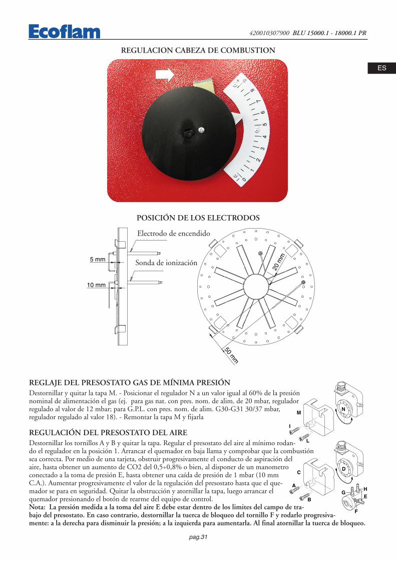
REGLAJE DEL PRESOSTATO GAS DE MÍNIMA PRESIÓNDestornillar y quitar la tapa M. - Posicionar el regulador N a un valor igual al 60% de la presiónnominal de alimentación el gas (ej. para gas nat. con pres. nom. de alim. de 20 mbar, reguladorregulado al valor de 12 mbar; para G.P.L. con pres. nom. de alim. G30-G31 30/37 mbar,regulador regulado al valor 18). - Remontar la tapa M y fijarla
REGULACIÓN DEL PRESOSTATO DEL AIREDestornillar los tornillos A y B y quitar la tapa. Regular el presostato del aire al mínimo rodan-do el regulador en la posición 1. Arrancar el quemador en baja llama y comprobar que la combustiónsea correcta. Por medio de una tarjeta, obstruir progresivamente el conducto de aspiración delaire, hasta obtener un aumento de CO2 del 0,5÷0,8% o bien, al disponer de un manometroconectado a la toma de presión E, hasta obtener una caída de presión de 1 mbar (10 mmC.A.). Aumentar progresivamente el valor de la regulación del presostato hasta que el que-mador se para en seguridad. Quitar la obstrucción y atornillar la tapa, luego arrancar elquemador presionando el botón de rearme del equipo de control.Nota: La presión medida a la toma del aire E debe estar dentro de los limites del campo de tra-bajo del presostato. En caso contrario, destornillar la tuerca de bloqueo del tornillo F y rodarlo progresiva-mente: a la derecha para disminuir la presión; a la izquierda para aumentarla. Al final atornillar la tuerca de bloqueo.
2,55
10 15
50
25
35
30
4045
20
0,4
0,6 0,9
3,0
1,5
2,1
1,8
2,42,7
1,2
I
L
MN
A
B
CD
E
F
GH
REGULACION CABEZA DE COMBUSTION
POSICIÓN DE LOS ELECTRODOS
50 mm
5 mm
10 mm
elettrodoaccensione
elettrodorivelazione 20
mm
Electrodo de encendido
Sonda de ionización

pag.32
420010307900 BLU 15000.1 - 18000.1 PR
ESEl controle de la corriente de ionización se efectúaconectando un microamperímetro de escala de 50µA (corriente continua)en serie al electrodo de ioni-zación. Una colocación errada del electrodo puedecomportar una reducción de la corriente de ioniza-ción y causar un bloqueo en seguridad del quema-dor, debido a una falta de detección de la llama. Eneste caso, comprobar la correcta colocación del elec-trodo, la conexión eléctrica y la toma a tierra delquemador. Normalmente, el valor de la a corriente de ionización es >20 µA.
24
min. 6 μA
LANDIS LFL1.622Microamperometro fondo scala 50 μA
CORRIENTE DE IONIZACIÓN
Microamperómetroescala de 50 µA.
DESMONTAJE DELLA CABEZA DE COMBUSTIONADVERTENCIA !
DESMONTAJE DEL TUBO DE LLAMA

pag.33
420010307900 BLU 15000.1 - 18000.1 PR
ES
DESCRIPCIÓN DEL CUADRO DE MANDOS DEL QUEMADOR
1 - fusible2 - lampe de thermal de securité3 - lampe de fonctionnement 4 - commutateur : 0 blocage des dispositifs pour le fonctionnement d'une position intermédiaire
fonctionnement à la puissance maximale
fonctionnement à la puissance minimale
AUTO fonctionnement automatique
5 - Interrupteur I / O6 - bouton de déblocage
43
5
2 1
0
AUTO
0I
GAS
6
ANOMALIAS DE FUNCIONAMIENTOCONTROL ANUAL: El control periódico del quemador (cabeza de combustión, electrodos etc.) tiene que ser efectuado por técnicos autori-zados una o dos veces cada año, según la utilización del quemador. Antes de proceder con las operaciones de manteni-miento, es aconsejable comprobar el estado general del quemador actuando de la manera siguiente:- Desconectar la clavija del quemador de la red. - Cerrar la válvula de cierre del gas. - Sacar la tapa del quemador y lim-
piar ventilador y conducto de aspiración del aire. - Limpiar la cabeza de combustión y comprobar la posición de loselectrodos. - Remontar el todo. - Comprobar la estanqueidad de las uniones del gas. - Comprobar la chimenea. -Arrancar el quemador y comprobar los parámetros de combustión (CO2 = 9,7% (G 20); 11,7% (G 30); 11,7% (G31); CO inferior a 75 ppm).
Antes de cada intervención comprobar:- Que hay corriente en la instalación y que el quemador sea conectado. - Que la presión del gas sea la correcta y la válvula de cierre esté abierta. - Que los equipos de control estén debidamente conectados.- Cuando todas estas condiciones se cumplen, arrancar el quemador presionando el botón de bloqueo y comprobar la
secuencia de encendido.
Breve guía de averías:- El quemador no arranca: comprobar el interruptor de arranque, los termostatos, el motor, la presión del gas, el equipo
de control de estanqueidad (si lo hay).- El quemador efectúa el prebarrido pero se pone en seguridad al final del ciclo: comprobar la presión del aire, el venti-
lador y el presostato del aire.- El quemador efectúa el prebarrido pero no se enciende: comprobar el montaje y la posición de los electrodos, el cable
de encendido, el transformador de encendido, el equipo de control llama y las electroválvulas del gas.- El quemador se enciende pero se pone en seguridad al cumplir del tiempo de seguridad: comprobar que fase y neutro
sean conectados correctamente; comprobar posición y conexión de la sonda de ionización; comprobar el equipo decontrol de llama.
- El quemador se enciende normalmente pero se pone en seguridad después unos minutos de funcionamiento: compro-bar el regulador de presión y el filtro del gas; controlar la presión del gas; controlar el valor de ionización (mín. 6 µA);comprobar los valores de la combustión.

34
420010307900 BLU 15000.1 - 18000.1 PR
RU
Индекс
1 - ТЕХНИЧЕСКИЕ ХАРАКТЕРИСТИКИ- ТЕХНИЧЕСКИЕ ХАРАКТЕРИСТИКИ . . . . . . . . . . . . . . . . . . . . . . . . . . . . . . . . . . . . . .p.35- РАБОЧИЙ ДИАПАЗОН . . . . . . . . . . . . . . . . . . . . . . . . . . . . . . . . . . . . . . . . . . . . . . . . . .p.35- ГАБАРИТНЫЕ РАЗМЕРЫ . . . . . . . . . . . . . . . . . . . . . . . . . . . . . . . . . . . . . . . . . . . . . . . .p.35
2 - МОНТАЖ- ЭЛЕКТРИЧЕСКИЕ СОЕДИНЕНИЯ . . . . . . . . . . . . . . . . . . . . . . . . . . . . . . . . . . . . . . . .p.36- ПОДКЛЮЧЕНИЕ К ГАЗОПРОВОДУ . . . . . . . . . . . . . . . . . . . . . . . . . . . . . . . . . . . . . . .p.36
3 - СТАРТЕР И РЕГУЛИРОВКИ- ЗАПУСК ГОРЕЛКИ . . . . . . . . . . . . . . . . . . . . . . . . . . . . . . . . . . . . . . . . . . . . . . . . . . . . .p.36- РЕГУЛИРОВАНИЕ ПРОЦЕССА СГОРАНИЯ . . . . . . . . . . . . . . . . . . . . . . . . . . . . . . . .p.36- РАБОЧИй ЦИКЛ ЭЛЕКТРОННОГО ОБОРУДОВАНИЯ . . . . . . . . . . . . . . . . . . . . . . . .p.37- ВОЗДУШНЫЙ СЕРВОПРИВОД . . . . . . . . . . . . . . . . . . . . . . . . . . . . . . . . . . . . . . . . . .p.37,38- РЕГУЛИРОВАНИЕ ПОЛОЖЕНИЯ ГОЛОВКИ . . . . . . . . . . . . . . . . . . . . . . . . . . . . . . .p.39- ТОК ИОНИЗАЦИИ . . . . . . . . . . . . . . . . . . . . . . . . . . . . . . . . . . . . . . . . . . . . . . . . . . . . .p.39- ДЕМОНТАЖ ГОЛОВКИ ГОРЕЛКИ . . . . . . . . . . . . . . . . . . . . . . . . . . . . . . . . . . . . . . .p.40- ПАНЕЛЬ УПРАВЛЕНИЯ ГОРЕЛК . . . . . . . . . . . . . . . . . . . . . . . . . . . . . . . . . . . . . . . . .p.41
4 - ПОЛЬЗА И ОБСЛУЖИВАНИЕ- ПЕРИОДИЧЕСКОЕ ОБСЛУЖИВАНИЕ . . . . . . . . . . . . . . . . . . . . . . . . . . . . . . . . . . . . .p.41
35
420010307900 BLU 15000.1 - 18000.1 PR
RU
mbar
2000 3000 4000 5000 6000 7000 8000 9000 10000
10
12
14
16
1000
2000 30001000
18
20
22
11000
0
2
4
6
8
24
26
28
30
12000 kW13000
32
34
36
38
40
kcal/hx 10004000 5000 6000 7000 8000 9000 10000 11000 12000 13000 14000 15000 16000 17000
14000 15000 16000 17000 18000 19000
BLU 15000.1 PR
BLU
18000.1 PR
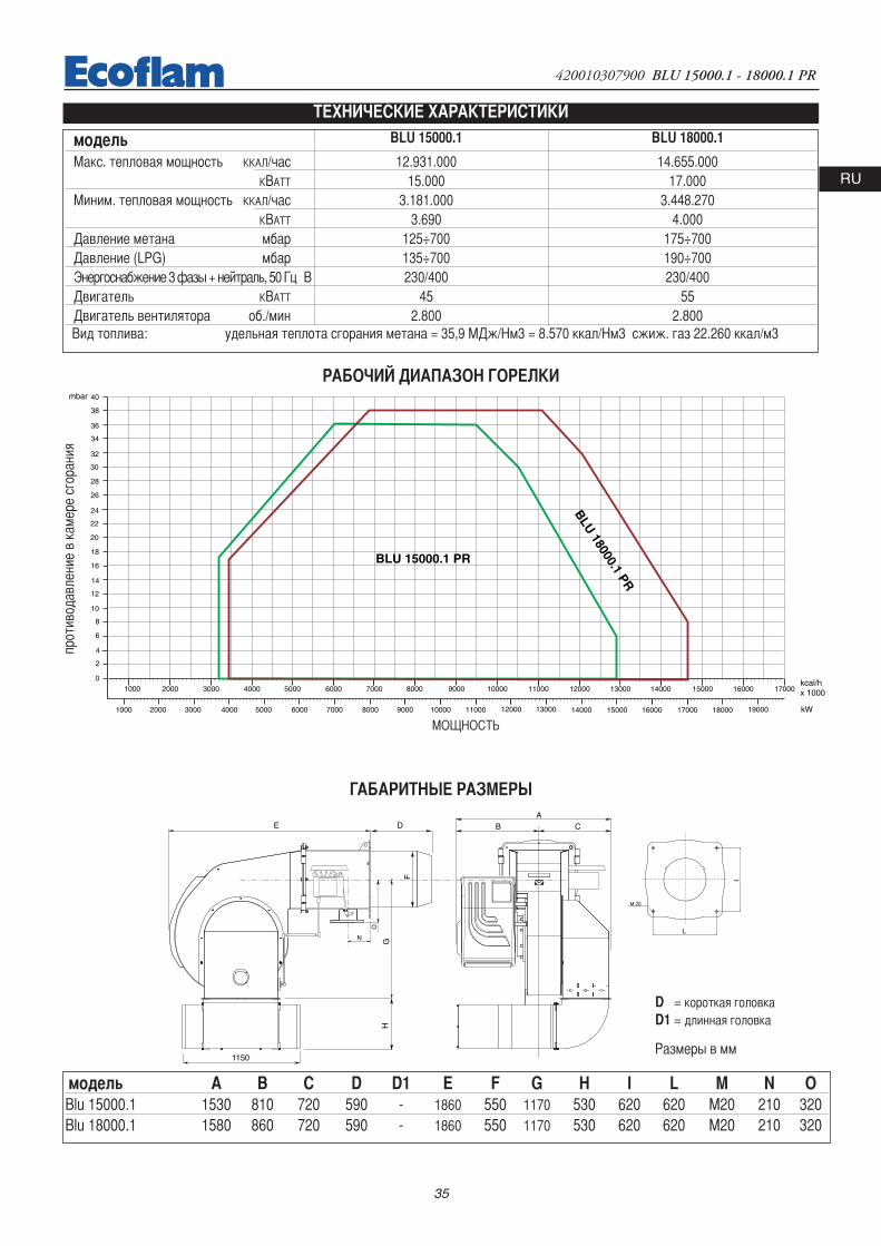
ТЕХНИЧЕСКИЕ ХАРАКТЕРИСТИКИ
РАБОЧИЙ ДИАПАЗОН ГОРЕЛКИ
ГАБАРИТНЫЕ РАЗМЕРЫ
модель BLU 15000.1 BLU 18000.1
Макс. тепловая мощность ККАЛ/час 12.931.000 14.655.000KВАТТ 15.000 17.000
Миним. тепловая мощность ККАЛ/час 3.181.000 3.448.270KВАТТ 3.690 4.000
Давление метана мбар 125÷700 175÷700Давление (LPG) мбар 135÷700 190÷700Энергоснабжение 3 фазы + нейтраль, 50 Гц В 230/400 230/400Двигатель KВАТТ 45 55Двигатель вентилятора об./мин 2.800 2.800Вид топлива: удельная теплота сгорания метана = 35,9 МДж/Нм3 = 8.570 ккал/Нм3 сжиж. газ 22.260 ккал/м3
L
M 20
I
E D
GH
1150
ACB
F
N
O
Размеры в мм
D = короткая головкаD1 = длинная головка
модель A B C D D1 E F G H I L M N OBlu 15000.1 1530 810 720 590 - 1860 550 1170 530 620 620 M20 210 320Blu 18000.1 1580 860 720 590 - 1860 550 1170 530 620 620 M20 210 320
прот
ивод
авле
ние
в ка
мере
сго
рани
я
МОЩНОСТЬ

36
420010307900 BLU 15000.1 - 18000.1 PR
RU
ЭЛЕКТРИЧЕСКИЕ СОЕДИНЕНИЯ Все двигатели горелок прошли заводские испытания при трехфазном напряжении 400 В 50 Гц, а цепи управления - приоднофазном напряжении 230 В 50 Гц + ноль. При необходимости обеспечить электропитание горелки от сети 230 Вольт 50 Гцбез нуля, необходимо выполнить подключения, руководствуясь соответствующей электрической схемой. Рабочий диапазонтеплового реле должен находиться в пределах потребляемой мощности двигателя.
РЕГУЛИРОВАНИЕ ПРОЦЕССА СГОРАНИЯ ВНИМАНИЕ: для правильного регулирования процесса сгорания и теплопроизводительности необходимо с помощьюсоответствующих приборов произвести анализ дымовых газов. Регулирование сгорания и теплопроизводительностивыполняется одновременно с анализом продуктов сгорания, при этом необходимо убедиться в правильности выполненныхзамеров. В любом случае показатели должны соответствовать действующим нормам безопасности. См. приведенные таблицу играфик. ЭТИ РАБОТЫ ДОЛЖНЫ ВЫПОЛНЯТЬСЯ КВАЛИФИЦИРОВАННЫМ ПЕРСОНАЛОМ, ИМЕЮЩИМСООТВЕТСТВУЮЩЕЕ РАЗРЕШЕНИЕ КОМПАНИИ "ЭКОФЛАМ".ВНИМАНИЕ: ВСЕ ПРЕДОХРАНИТЕЛЬНЫЕ УСТРОЙСТВА (РЕЛЕ ДАВЛЕНИЯ ВОЗДУХА, РЕЛЕ МИНИМАЛЬНОГОДАВЛЕНИЯ ГАЗА, ГАЗОВЫЕ ЭЛЕКТРОКЛАПАНЫ И СТАБИЛИЗАТОР ДАВЛЕНИЯ) ТАРИРУЮТСЯ СПЕЦИАЛИСТАМИ,ИМЕЮЩИМИ СООТВЕТСТВУЮЩЕЕ РАЗРЕШЕНИЕ КОМПАНИИ "ЭКОФЛАМ", И ПОСЛЕ ЗАПУСКА ГОРЕЛКИ ДОЛЖНЫ БЫТЬЗАПЛОМБИРОВАНЫ.
ПОДКЛЮЧЕНИЕ К ГАЗОПРОВОДУ После подключения горелки к газопроводу проверить его герметичность. Проверить состояние дымохода (герметичность иотсутствие в нем препятствий и т.п.). Открыть газовый вентиль и осторожно продуть газопровод в направлении гнезда отборадавления; проверить давление с помощью манометра . Подать напряжение и установить термостаты на требуемое значениетемпературы. После включения термостата в цепь специальное устройство проверяет герметичность клапанов. По завершенииконтроля горелка получает разрешение на выполнение пускового цикла.
ЗАПУСК И РЕГУЛИРОВАНИЕ ГОРЕЛКИ Прежде чем зажечь горелку, следует убедиться, что ее монтаж был выполнен правильно. Проверить соответствиесхемам электросоединений и состояние трубопроводов системы отопления. До подачи электроэнергии убедиться, чтонапряжение соответствует параметрам, указанным на табличке технических характеристик. Электрическая схема ипусковой цикл описаны отдельно. Для подключения к горелке панели управления смотрите прилагаемую схему.Особое внимание следует уделить положению нуля и фазы: ни в коем случае не менять их местами! Проверитьзаземление системы отопления. Для трехфазных двигателей обязательно проверить направление вращения(указано стрелкой). Продуть газопровод для удаления из него посторонних веществ и стравить из него воздух.Удостовериться, что давление газа находится в пределах, указанных на табличке. Это делается с помощьюповерочного манометра, который устанавливается в специальное гнездо отбора давления на горелке. Затемзапускается двигатель, и начинается предварительная продувка горелки. Примерно за 30 сек. сервоприводполностью открывает воздушную заслонку. Когда заслонка оказывается в полностью открытом положении, поимпульсу, поступающему на аппаратуру управления, начинается цикл предварительной продувкипродолжительностью около 66 сек (36 сек LFL1.333). По завершении продувки сервопривод перемещает заслонку вположение первой ступени, после чего становится возможен розжиг горелки на минимальной мощности.Одновременно с этим подается напряжение на трансформатор розжига, и спустя 3 сек. (предварительный розжиг)напряжение подается на пилотный клапан. Спустя 2 сек. после открывания пилотного клапана. трансформаторисключается из электрической цепи. Если розжиг не происходит, не более чем через 2 сек. происходит аварийнаяостановка горелки. Дроссельный клапан регулирует расход газа в огневой головке. Горелка работает наминимальной мощности (около 30% от максимальной). Модуляционное устройство управляет сервоприводом: взависимости от потребности системы отопления сервопривод переходит в положение максимального раскрытия либоостанавливается в среднем положении. За счет изменения положения сервопривода гарантируетсяпропорциональность расхода газа и воздуха таким образом, что при любой мощности (30% - 100%) обеспечиваетсяоптимальное качество сгорания.При выключении горелки сервопривод возвращается в положение "закрыто".ВАЖНЫЕ РЕКОМЕНДАЦИИ:После тарирования специалистом уставки всех регулируемых устройств должны быть зафиксированы. После каждойрегулировки выполнять анализ дымовых газов в дымоходе.riore a 75 ppm.

37
420010307900 BLU 15000.1 - 18000.1 PR
RU
ВОЗДУШНЫЙ СЕРВОПРИВОД LANDIS & STAEFA SQM 50.481A2 Для доступа к регулировочным кулачкам снять крышку. Регулировка кулачков производится с помощью специальногоключа в комплекте следующим образом:
I - Кулачок для регулировки расхода воздуха на максимальной мощности II - Кулачок для регулировки положения заслонки при гашенииIII - Кулачок для регулировки расхода воздуха на минимальной мощностиIV - Кулачок для регулировки расхода воздуха нижней ступени мощностиV - не используетсяVI - не используетсяVII - не используетсяVIII - не используется
кулачок VIII неиспользуется
0min
100%
t1 t2
t4
t3
t6t5
t1 t2
t4
t3
РАБОЧИй ЦИКЛ ЭЛЕКТРОННОГО ОБОРУДОВАНИЯ LANDIS & STAEFA LFL1.622-1.333
Нормальный рабочий режимРабочий цикл в отсутствие
пламени при розжиге
Реле давления газа
Двигатель вентилятора
Реле давления воздуха
Трансформатор розжига
Газовый клапан
разрешение мин/макс
воздушн. заслонка
газовая заслонка
Обнаружение пламени
индикация блокировки
Электронное оборудованиеконтроля пламени запускаетвентилятор горелки дляпредварительной продувкитопки, при этом воздушноереле контролируетсоздаваемое вентиляторомдавление. Послепредварительной продувкивступает в работутрансформатор розжига, иодновременно открываютсягазовые клапаны(предохранительный клапанVS и рабочий клапан VL). Вслучае неудачного розжигаили случайного затуханиябезопасность обеспечивается датчиком обнаружения пламени, которыйблокирует оборудование в течение времени аварийной остановки. В случаеотсутствия газа или значительного падения давления реле минимальногодавления газа прерывает работу горелки.
наименование ∏t1 время ожидания подтверждения давл. воздуха 8”t2 время продувки 66”(36”)t3 время аварийной остановки 2“t4 время розжига 4”t5 время разрешения раб. топливн. клапана
для работы на мин. мощн. 10”t6 время разрешения раб. топливн. клапана
для работы на макс. мощн. 10”
РЕГУЛИРОВАНИЕ ПРОЦЕССА СГОРАНИЯВНИМАНИЕ: Регулирование сгорания и теплопроизводительности должно выполняться одновременно с анализомпродуктов сгорания, при этом необходимо использовать соответствующие приборы. Убедитесь в правильностивыполненных замеров, а также в том, что полученные результаты соответствуют действующим нормамбезопасности. Регулировка должна выполняться квалифицированным персоналом, имеющим соответствующееразрешение компании "ЭКОФЛАМ".

38
420010307900 BLU 15000.1 - 18000.1 PR
RU
РЕГУЛИРОВАНИЕ РАСХОДА ВОЗДУХА И ГАЗА
РАСЧЕТ МОЩНОСТИ ГОРЕЛКИЗамерить по счетчику расход газа в литрах и время замера всекундах. Мощность в кВт рассчитывается по следующейформуле: e x f = kW
sec
e = кол-во газа в литрахsec = время в секундах метан = 34,02бутан = 116пропан = 88
f
COMMUTATORE
0
AUTO
0 = bloccaggio degli apparati per il funzionamento in una posizione intermadia = funzionamento alla massima potenza = funzionamento alla minima potenza AUTO = funzionamento automatico
Part. 2+
+
--
+
--
Part. 3
аппаратура управления заблокирована дляработы в среднем диапазоне мощностиработа на максимальной мощности работа на минимальной мощности автоматический режим
ПЕРЕКЛЮЧАТЕЛЬ
дет.
дет.
РЕГУЛИРОВКА МИНИМАЛЬНОЙ МОЩНОСТИ ГОРЕЛКИ – ВОЗДУХ И ГАЗУстановите переключатель на панели управления в положение 2 и выполните следующие действия:Отрегулируйте минимальный расход газа, вращая соответствующим ключом дроссельный клапан, пока не будетдостигнут требуемый расход газа, что определяется по результатам анализа процесса сгорания.
РЕГУЛИРОВКА МАКСИМАЛЬНОГО РАСХОДА ГАЗАПоставьте переключатель на панели управления в положение 1 и выполните следующие действия:Отрегулируйте максимальный расход газа (регулировка электромагнитного клапана показана на рисунке) илиотрегулируйте газовым регулятором давление газа.
РЕГУЛИРОВКА МАКСИМАЛЬНОГО РАСХОДА ВОЗДУХАРегулировка максимального расхода воздуха (см. рисунок, деталь 2). Ослабьте гайку, блокирующую приводной штоквоздушной заслонки; правильный расход воздуха устанавливается по результатам анализа продуктов сгорания.
РЕГУЛИРОВКА РАБОТЫ ГОРЕЛКИ НА СРЕДНЕЙ МОЩНОСТИПереключателем включить сервопривод (закрывание или открывание) и прервать его ход, переведя переключательв положение 0; выполнить регулировку по приведенным ниже инструкциям. Повторить эту операцию для всехостальных кулачков. Регулировка расхода газа на средней мощности (см. рисунок, деталь 3): - при помощишестигранного гаечного ключа изменить изгиб направляющей пластинки кулачков. При вращении по часовой стрелкерасход уменьшается, против часовой стрелки – увеличивается.

39
420010307900 BLU 15000.1 - 18000.1 PR
RU
2,55
10 15
50
25
35
30
4045
20
0,4
0,6 0,9
3,0
1,5
2,1
1,8
2,42,7
1,2
I
L
MN
A
B
CD
E
F
GH
РЕГУЛИРОВАНИЕ РЕЛЕ ДАВЛЕНИЯ ВОЗДУХА Отвинтить винты A и B и снять крышку C и установить реле давления наминимум, поставив регулятор D в положение 1. Запустить горелку на 1-й ступенимощности; убедиться, что процесс сгорания проходит качественно. С помощьюкартонки постепенно закрывать всасывающий воздуховод вплоть до повышениязначения СО2 на 0,5 - 0,8%, либо при наличии манометра, подключенного кгнезду отбора давления E - до уменьшения давления на 0,1 мбар (~ 10 мм в.с.).Постепенно увеличивать тарировочное значение реле давления вплоть доаварийного гашения горелки. Освободить всасывающий воздуховод, установитьобратно крышку С и затем нажатием кнопки перезапуска контрольнойаппаратуры вновь запустить горелку.
реле давлениявоздуха
реле давлениягаза
ТАРИРОВАНИЕ РЕЛЕ МИНИМАЛЬНОГО ДАВЛЕНИЯ ГАЗАОтвинтить винты I и L и снять крышку M. Установить регулятор N на значениеравное 60% номинального давления газа (например, при номинальном давлении метана 20мбар регулятор устанавливается на значение 12 мбар; для сжиженного газа сноминальным давлением 30/37 мбар регулятор устанавливается на значение 18мбар). Установить на место крышку M и ввернуть винты I и L.
РЕГУЛИРОВАНИЕ ПОЛОЖЕНИЯ ГОЛОВКИ ГОРЕЛИ
ПОЛОЖЕНИЕ ЭЛЕКТРОДОВ
50 mm
5 mm
10 mm
elettrodoaccensione
elettrodorivelazione 20
mm
электродобнаружения пламени
электрод розжига

40
420010307900 BLU 15000.1 - 18000.1 PR
RU
Контроль тока ионизации выполняется с помощьюмикроамперметра постоянного тока с глубинойшкалы до 50 μA, который подключаетсяпоследовательно к электроду розжига.Неправильное положение электрода можетпривести к понижению тока ионизации и, какследствие, к аварийной остановке горелки,вызванной тем, что пламя не было обнаружено. Втаких случаях следует проверить правильностьположения электрода, его электрическиесоединения и заземление горелки. Как правило, сила тока ионизации должна быть не ниже 20 μA.
24
min. 6 μA
LANDIS LFL1.622Microamperometro fondo scala 50 μA
ОБНАРУЖЕНИЕ ПЛАМЕНИ
микроамперметрс глубиной шкалы 50 μА
ДЕМОНТАЖ ГОЛОВКИ ГОРЕЛКИОБРАТИТЕ ОСОБОЕ ВНИМАНИЕ!
ДЕМОНТАЖ СТАКАНА

41
420010307900 BLU 15000.1 - 18000.1 PR
RU
НЕИСПРАВНОСТИ И СПОСОБЫ ИХ УСТРАНЕНИЯПЛАНОВОЕ ОБСЛУЖИВАНИЕПериодическое обслуживание горелки (огневой головки, электродов и т.д.) должно выполняться квалифицированнымперсоналом. В зависимости от условий эксплуатации это делается 1 или 2 раза в год. Прежде, чем приступить к проверке ипоследующему обслуживанию горелки рекомендуется произвести её общий осмотр. Для этого: - Отключите энергоснабжениегорелки (отсоедините штекер).- Закройте запорный газовый кран. Снимите крышку горелки, прочистите вентилятор и всасывающий воздуховод.- Прочистите головку горелки и проверьте положение электродов. Установите обратно все детали. Проверьте герметичностьгазовых соединений.- Проверьте дымоход. Запустите горелку. Выполните анализ продуктов сгорания: С02 = 9,5 - 9,8, СО = не более 75 ррm)
ПЕРЕД КАЖДОЙ ИЗ ОПИСАННЫХ ДАЛЕЕ ОПЕРАЦИЙ НЕОБХОДИМО УДОСТОВЕРИТЬСЯ В ТОМ, ЧТО:- в сети имеется напряжение, а горелка подключена. в сети имеется требуемое давления газа, и запорный газовый краннаходится в открытом положении. - Предохранительные устройства и приборы управления подключены правильно. Если всевышеупомянутые условия соблюдены, нажатием кнопки перезапуска запустите горелку. Проверьте рабочий цикл горелки.
ГОРЕЛКА НЕ ЗАПУСКАЕТСЯ:- Проверьте выключатель, термостаты, двигатель и давление газа.
ПОСЛЕ ПРЕДВАРИТЕЛЬНОЙ ПРОДУВКИ ПРОИСХОДИТ БЛОКИРОВКА ГОРЕЛКИ:- Проверьте давление воздуха и вентилятор. - Проверьте исправность реле давления воздуха.
ПОСЛЕ ПРЕДВАРИТЕЛЬНОЙ ПРОДУВКИ РОЗЖИГ ГОРЕЛКИ НЕ ПРОИСХОДИТ:- Проверьте правильность установки электродов и их положение. Проверьте провод розжига.- Проверьте трансформатор розжига. Проверьте предохранительные устройства.
ПОСЛЕ РОЗЖИГА ПО ИСТЕЧЕНИИ ВРЕМЕНИ АВАРИЙНОЙ ОСТАНОВКИ ПРОИСХОДИТ БЛОКИРОВКА ГОРЕЛКИ:- Проверьте правильность подключения фазы и нуля. - Проверьте газовые электроклапаны.- Проверьте положение и правильность подключения электрода обнаружения пламени. - Проверьте ионизационный электрод.- Проверьте предохранительные устройства.
БЛОКИРОВКА ГОРЕЛКИ ПРОИСХОДИТ ПОСЛЕ ЕЁ НЕПРОДОЛЖИТЕЛЬНОЙ НОРМАЛЬНОЙ РАБОТЫ:- Проверьте регулятор давления и газовый фильтр. С помощью манометра проверьте давление газа.- Проверьте параметры обнаружения пламени (не менее 6 μА).
ПАНЕЛЬ УПРАВЛЕНИЯ ГОРЕЛК
1 - Fuse2 - Termal lock-out lamp3 - Working lamp4 - Selector : 0 Loking of devoices for operating at intermediate outputs
Operation at max. output
Operation at min. output
AUTO Automatic operation
5 - Main switch I / O6 - Lockout disable push button7 - Modulating unit RWF 40
43
5
2 1
0
AUTO
0I
GAS
6
фиксированные параметры оборудования для работы на средней мощности
работа на максимальной мощности
работа на минимальной мощности
работа в автоматическом режиме
индикатор температурной блокировки
индикатор рабочего режима
кнопка перезапуска
Выключатель Вкл./Выкл.
Гнездо предохранителя
Переключатель режимов

42
420010307900 BLU 15000.1 - 18000.1 PRIT
EN
FR
ES
RU
F
1
ED
23
4
CBA
12
34
56
78
FED
56
7
CB
8
A
TOT.
SHEE
T
SHEE
TDE
SIGNE
RDE
SCRIP
TION
DATE
FIST
CREA
TION
CODE
SIGNA
TURE
R&D
DEPA
RTM
ENT
CONT
ROLL
EREc
oflam
Bru
ciat
ori
SERV
OMOT
OR
FLAM
E SEN
SOR
S.p.
AEC
N FIR
ST CR
EATIO
N
BY TERM LAWS WE RESERVED THE PROPERTY OF THIS WIRING DIAGRAM WITH PROHIBITION OF USE AND REPRODUCTION
LEAK
AGE C
ONTR
OL
CONT
ROL B
OX
DATE
ECN
MOD
ICAT
ION
MOD
IFICA
TION
DESC
RIPTIO
NEC
N M
ODIFI
CATIO
N
BLU
1500
0.1-1
8000
.1 PR
A.PO
ZZOB
ON
13-0
5-20
10
2
4201
1002
9600
1 A
.RIGO
NI
LAND
IS SQ
M 50
.481A
2
ER
RBA1
0PM
138
LAND
IS LF
L 1.33
3-1.6
22
DUNG
S VPS
504
ER
SA s.
r
KMV1
KMV2
KMV1
KMV3
KMV3
KMV1
KMV2
PT
STSPT
STC
FMV
95 96FM
V97 98
78
965
4
23
1
1112
10 1210
11
31
2
65
4 78
9
21
2
HLB
KTav
v
FMV
3M
MV
W1
V1U1
YVGP
HLF
HLB
KASA
MA
12
30
TVT
P
SPA
HLBT
SAL
FULINE
LOAD
Z
HLF
TP
STAB
YVGS
YVG
TP
SPGm
in
SAM
A
12
30
pos 0
: FER
MO
/ STO
P
pos 2
: BAS
SA FI
AMM
A/LO
W FL
AME/
1re A
LLUR
E/BA
JA LL
AMA
pos 3
: AUT
OMAT
ICO/
AUTO
MAT
IC/A
UTOM
ATIQ
UE/A
UTOM
ATIC
O
pos 1
: ALT
A FIA
MM
A/HI
GH FL
AME/
2meA
LLUR
E/AL
TA LL
AMA
COM
MUT
ATOR
E MAN
UALE
-AUT
OMAT
ICO
CONM
UTAD
OR M
ANUA
L-AUT
OMAT
ICO
INTE
RRRU
PTEU
R MAN
UEL-A
UTOM
ATIQ
UESW
ITCH
MAN
UAL-A
UTOM
ATIC
Mas
chio
Fem
min
a
V2U2
W2
32
14
S3T2
NT1
L1
717
166
2625
54
2415
2714
2322
133
212
111
21
M1 N
LAND
IS SQM
50.48
1A2
3224
2321
1920
2231
1816
1713
1415
119
108
67LA
NDIS
LFL 1
.333 -
LFL 1
.622
125
34
21
1011
1213
50 H
z 400
V
PE R T NS
85
67
TS
RN
Q
9
YELLOW-GREEN
BLACK
BROWN
BLUE
DUNG
S VPS
504
T7T8
B5T6
NL1
L1S3
NT1
T2

43
420010307900 BLU 15000.1 - 18000.1 PR IT
EN
FR
ES
RUTOT.
SHEE
T
SHEE
TDE
SIGNE
RDE
SCRIP
TION
DATE
FIST
CREA
TION
CODE
SIGNA
TURE
R&D
DEPA
RTM
ENT
CONT
ROLL
EREc
oflam
Bru
ciat
ori
SERV
OMOT
OR
FLAM
E SEN
SOR
S.p.
AEC
N FIR
ST CR
EATIO
N
BY TERM LAWS WE RESERVED THE PROPERTY OF THIS WIRING DIAGRAM WITH PROHIBITION OF USE AND REPRODUCTION
LEAK
AGE C
ONTR
OL
CONT
ROL B
OX
DATE
ECN
MOD
ICAT
ION
MOD
IFICA
TION
DESC
RIPTIO
NEC
N M
ODIFI
CATIO
N
BLU
1500
0.1-1
8000
.1 PR
A.PO
ZZOB
ON
13-0
5-20
10
2
4201
1002
9600
2 A
.RIGO
NI
LAND
IS SQ
M 50
.481A
2
ER
RBA1
0PM
138
LAND
IS LF
L 1.33
3-1.6
22
DUNG
S VPS
504
F
1
ED
23
4
CBA
12
34
56
78
FED
56
7
CB
8
A
CONM
UTAD
OR M
ANUA
L-AUT
OMAT
ICO
COM
MUT
ATOR
E MAN
UALE
-AUT
OMAT
ICOSW
ITCH
(MAN
UAL-A
UTOM
ATIC
))IN
TERR
UPTE
UR M
ANUE
L-AUT
OMAT
IQUE
INTE
RRUP
TOR D
E LIN
EAIN
TERR
UPTE
UR D
E LIG
NEW
ORKIN
G SW
ITCH
PRES
OSTA
TO A
IREPR
ESSO
STAT
AIR
AIR P
RESS
URE S
WITC
H
TERM
OSTA
TO CA
LDER
ATH
ERM
OSTA
T CHA
UDIER
EBO
ILER T
HERM
OSTA
T
TERM
OSTA
TO D
E SEG
URID
ADTH
ERM
OSTA
T DE S
ECUR
ITESA
FETY
THER
MOS
TAT
ESPIA
DE B
LOQU
EO RE
LE TE
RMICO
LAM
PE D
E THE
RMAL
DE S
ECUR
ITETH
ERMA
L LOC
K-OU
T LAM
PLA
MPA
DA D
I BLO
CCO
TERM
ICO
TERM
OSTA
TO D
I SIC
UREZ
ZA
TERM
OSTA
TO CA
LDAI
A
PRES
SOST
ATO
ARIA
INTE
RRUT
TORE
DI L
INEA
SAMA
HLBT
STS
STC
SPA
SAL
INTE
RRUP
TOR G
ENER
AL CO
N FU
SIBLE
INTE
RRUP
TEUR
GEN
ERAL
AVEC
FUSIB
LEMA
IN SW
ITCH
WITH
FUSE
FILTR
O DE
PROT
ECIO
N A
NTID
ISTUR
BIOFIL
TRE A
NTIPA
RASIT
ESAN
TJAM
MIN
G FIL
TER
FUSIB
LEFU
SIBLE
MOT
OR VE
NTILA
DOR
MUT
EUR V
ENTIL
ATEU
RM
OTOR
FAN
TRAN
SFOR
MADO
RTR
ANSF
ORMA
TEUR
D'AL
LUMA
GEIG
NITIO
N TR
ANSF
ORM
ER
ESPIA
DE B
LOQU
EOLA
MPE
DE S
ECUR
ITELO
CK-O
UT LA
MP
RELE
' TER
MICO
MOT
OR VE
NTILA
DOR
RELA
IS TH
ERM
IQUE
MOT
EUR V
ENTIL
ATEU
RM
OTOR
THER
MAL R
ELAY
(FAN
MOT
OR)
TELE
RRUP
TOR M
OTOR
VENT
ILATO
RCO
NTAC
TEUR
MOT
EUR V
ENTIL
ATEU
RRE
MOT
E CON
TROL
SWITC
H (FA
N M
OTOR
)CO
NTAT
TORE
MOT
ORE V
ENTIL
ATOR
E
LAM
PADA
DI B
LOCC
O
RELE
' TER
MICO
MOT
ORE V
ENTIL
ATOR
E
TRAS
FORM
ATOR
E
MOT
ORE V
ENTIL
ATOR
E
FUSIB
ILE
FILTR
O AN
TIDIST
URBO
INTE
RRUT
TORE
GEN
ERAL
E CON
FUSIB
ILE
KMV2
HLB
FMV
ERTVMV
FUFU
SE
ZQ
ESPIA
DE F
UNCI
ONAM
IENTO
LAM
PE D
E FON
CTIO
NNEM
ENT
LAM
PADA
DI F
UNZIO
NAM
ENTO
PRES
OSTA
TO G
AS D
E MIN
IMA
POT.
HLF
WOR
KING
LAM
P
GAS P
RESS
URE S
WITC
H M
IN
HIGH
-LOW
FLAM
E THE
RMOS
TAT
PRES
SOST
ATO
GAS D
I MIN
IMA
PRES
SOST
AT G
AZ PR
ESSIO
N M
IN
ELET
TROV
ALVO
LA G
AS D
I SIC
UREZ
ZAEX
TRA
SAFE
TY G
AS SO
LENO
ID VA
LVE
ELEC
TROV
ANNE
GAZ
DE S
ECUR
ITEEL
ECTR
OVAL
VULA
GAS
DE S
EGUR
IDAD
ELET
TROV
ALVO
LA G
AS D
I PRIM
A FIA
MMA
FIRST
STAG
E GAS
SOLE
NOID
VALV
EEL
ECTR
OVAN
NE G
AZ PE
TITE A
LLUR
EEL
ECTR
OVAL
VULA
GAS
DE 1
^ LL
AMA
THER
MOS
TAT G
RAND
E-PET
IRE A
LLUR
ETE
RMOS
TATO
DE A
LTA-
BAJA
LLAM
A
TERM
OSTA
TO D
I ALT
A-BA
SSA
FIAM
MA
YVGS
SPGm
in
YVG
STAB
KARE
LE'
RELA
YRE
LAIS
RELE
'
YVGP
ELET
TROV
ALVO
LA G
AS PI
LOTA
PILOT
FLAM
E SOL
ENOI
D GA
S VAL
VEEL
ECTR
OVAN
NE G
AZ PI
LOTE
ELEC
TROV
ALVU
LA G
AS PI
LOTO
KMV1
KMV3
CONT
ATTO
RE D
I STE
LLA
STAR
CONT
ACTO
R CO
NTAC
TEUR
D'ET
OILE
CO
NTAT
TORE
DI S
TELL
A
CONT
ATTO
RE D
I TRIA
NGOL
ODE
LTA
CONT
ACTO
RCO
NTAC
TEUR
TRIA
NGLE
CONT
ATTO
RE D
I TRIA
NGOL
O
SA s.
rPU
LSAN
TE D
I SBL
OCCO
APP
AREC
CHIAT
URA
RESE
T LOC
K OUT
BUTT
ONBO
UTON
DE D
EBLO
CAGE
DU
COFF
RE D
E SEC
UR.
REAR
ME D
E LA
CENT
RALIT
A
ELET
TROD
O DI
RIVE
LAZIO
NEIO
NISA
TION
PROB
EEL
ECTR
ODE D
'IONI
SATIO
NEL
ECTR
ODO
DE IO
NIZA
CION
KTav
v.TE
MPO
RIZZA
TORE
ELET
T. AV
V.TO
STEL
LA/T
RINAG
OLO
ELEC
TRON
IC TI
MER
WITH
STAR
/DEL
TA ST
ARTE
RTE
MPO
RIZAD
OR EL
ÉCTR
ONICO
PREP
ARAD
O PA
RATE
MPO
RIZAD
OR EL
ÉCTR
ONICO
PREP
ARAD
O PA
RA

Ecoflam Bruciatori S.p.A. via Roma, 64 - 31023 RESANA (TV) - Italy - tel. 0423.719500 - fax 0423.719580 http://www.ecoflam-burners.com - e-mail: [email protected]
"società soggetta alla direzione e al coordinamento della Ariston Thermo S.p.A., via A. Merloni, 45 - 60044 Fabriano (An) CF 01026940427"
La ECOFLAM BRUCIATORI S.p.A si riserva il diritto di apportare ai prodotti quelle modifiche che riterrà necessarie outili, senza pregiudicarne le caratteristiche principali.
ECOFLAM BRUCIATORI S.p.A. reserves the right to make any adjustments, without prior notice, which it considersnecessary or useful to its products, without affecting their main features.
La Maison ECOFLAM BRUCIATORI S.p.A. se réserve le droit dʼapporter les modifications quʼelle jugera nécessaires ouutiles à ses produits sans pour autant nuire à leurs caractéristiques principales.
ECOFLAM BRUCIATORI S.p.A. se reserva el derecho a introductor en sus productos todas las modificaciones queconsidere necesarias o utiles, sin prejudicar sus caracteristicas.
“Экофлам С.п.А.” оставляет за собой право вносить в конструкцию оборудования любые необходимыеизменения без особого предупреждения.
ТЕТАН Инженерные Системы Партнер Ecoflam в Украине
ул. Здолбуновская 7-Д, г. Киев, Украина тел./факс: +380 (44) 362 33 00email: [email protected]
tetan.ua


![ПОРЯДОК РАЗРАБОТКИ, УЧЕТА, ИЗМЕНЕНИЙ ... - Gazprom · 2016-06-14 · [СТО Газпром 1.14-2009, пункт 3.7] ... [СТО Газпром 18000.1-001-2014,](https://img.pdfslide.tips/doc/110x75/5f27484df3b40c45190f1c3b/-oe-gazprom.jpg)