Embed Size (px)
Citation preview
8
CC HTVentilatori assiali intubati • F400 - F300/120 - F200 (certifi cati secondo EN 12101-3)DuctAxialFanF400-F300/120-F200(certifiedaccordingtoEN12101-3)
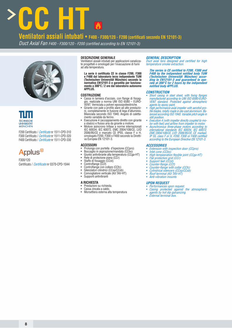
DESCRIZIONE GENERALEVentilatori assiali intubati per applicazioni canalizza-te progettati e omologati per l’evacuazione di fumi ad alta temperatura.
La serie è certifi cata CE in classe F200, F300 e F400 dal laboratorio terzo indipendente TUM (Technischen Universität München) secondo la normativa EN12101-3 e garantita per funziona-mento a 300°C / 2 ore dal laboratorio autonomo APPLUS.
COSTRUZIONE• Cassa in lamiera d’acciaio, con fl ange di fi ssag-
gio, realizzate a norma UNI ISO 6580 – EURO-VENT. Verniciata a polveri epossipoliestiriche.
• Girante con pale a profi lo alare ad alte prestazio-ni, completamente in fusione di lega d’alluminio. Bilanciata secondo ISO 1940. Angolo di caletta-mento variabile da fermo.
• Esecuzione 4 (accoppiamento diretto con girante a sbalzo) e fl usso aria da girante a motore.
• Motore asincrono trifase a norme internazionali IEC 60034, IEC 60072, EMC 2004/108/CE, LVD 2006/95/CE e marcato CE IP55, classe F o H, omologato F200, F300 o F400 secondo la Diretti-va Europea EN 12101-3.
ACCESSORI• Prolunga con portella d’ispezione (CCpro)• Boccaglio in aspirazione/mandata (CCbo)• Giunto antivibrante alta temperatura (CCga-HT)• Rete di protezione piana (CCr)• Staffe di fi ssaggio (CCst)• Controfl ange (CCf)• Controfl ange con collare (CCfc)• Silenziatori cilindrici (CCsa/CCsb)• Convogliatore verticale (Kit TAV-HT)• Supporti antivibranti
A RICHIESTA• Prestazioni su richiesta.• Cassa zincata a caldo.• Morsettiera esterna alta temperatura
GENERAL DESCRIPTIONDuct axial fans designed and certifi ed for high temperature smoke extraction. The series is CE certifi ed to F200, F300 and
F400 by the indipendent notifi ed body TUM (Technischen Universität München) accor-ding to EN12101-3 and guaranteed to ope-rate at 300°C for 2 hours by the indipendent notifi ed body APPLUS.
CONSTRUCTION• Short casing in steel sheet, with fi xing fl anges
manufactured according to UNI ISO 6580-EURO-VENT standard. Protected against atmospheric agents by epoxy paint.
• High performance axial impeller with aerofoil pro-fi le blades, totally made in die-cast aluminium. Ba-lanced according ISO 1940. Variable pitch angle in still position.
• Execution 4 (with impeller directly coupled to mo-tor with feet) and airfl ow from impeller to motor.
• Asynchronous three-phase motors according to international standards IEC 60034, IEC 60072, EMC 2004/108/CE, LVD 2006/95/CE, CE marked, IP 55, class F or H, F200, F300 or F400 certifi ed according to the European Directive EN 12101-3.
ACCESSORIES• Extension with inspection door (CCpro)• Inlet cone (CCbo)• High tempeeration fl exible joint (CCga-HT)• Flat protection grid (CCr)• Support feet (CCst)• Counter-fl ange (CCf)• Counter-fl ange with collar (CCfc)• Cylindrical silencers (CCsa/CCsb)• Roof terminal (Kit TAV-HT)• Anti-vibration mounts
UPON REQUEST• Performances upon request. • Casing protected against the atmospheric
agents by hot dip galvanizing.• External terminal box.
F200 Certifi cato / Certifi cate nr 1511-CPD-310F300 Certifi cato / Certifi cate nr 1511-CPD-320F400 Certifi cato / Certifi cate nr 1511-CPD-330
F300/120 Certifi cato / Certifi cate nr 0370-CPD-1044
9
DIMENSIONI Dimensions CC HT
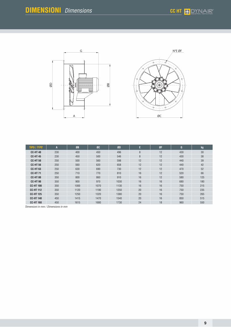
TIPO / TYPE A ØB ØC ØD E ØF G kg
CC-HT 40 230 400 450 496 8 12 430 30CC-HT 45 230 450 500 546 8 12 430 38CC-HT 50 250 500 560 598 12 12 440 39CC-HT 56 250 560 620 658 12 12 440 42CC-HT 63 250 630 690 730 12 12 470 52CC-HT 71 250 710 770 810 16 12 520 66CC-HT 80 350 800 860 910 16 12 580 125CC-HT 90 350 900 970 1030 16 16 680 180CC-HT 100 350 1000 1070 1130 16 16 750 215CC-HT 112 350 1120 1190 1250 20 16 750 235CC-HT 125 350 1250 1320 1380 20 16 750 265CC-HT 140 450 1415 1470 1540 20 16 850 515CC-HT 160 450 1615 1680 1730 24 18 960 550
Dimensioni in mm / Dimensionsinmm
G
ØB
A
ØD
N°E ØF
ØC

10
TIPOTYPE A A1 ØB ØC ØD E ØF kg
CCpro 40 200 430 400 450 496 8 12 6
CCpro 45 200 430 450 500 546 8 12 7
CCpro 50 200 450 500 560 598 12 12 8
CCpro 56 200 450 560 620 658 12 12 9
CCpro 63 240 490 630 690 730 12 12 11
CCpro 71 280 530 710 770 810 16 12 13
CCpro 80 240 590 800 860 910 16 12 20
CCpro 90 340 690 900 970 1030 16 16 31
CCpro 100 410 760 1000 1070 1130 16 16 39
CCpro 112 410 760 1120 1190 1250 20 16 58
CCpro 125 410 760 1250 1320 1380 20 16 65
CCpro 140 510 960 1415 1470 1540 20 16 88
CCpro 160 510 960 1615 1680 1730 24 18 98
Dimensioni in mm / Dimensionsinmm
TIPOTYPE A ØB ØC ØD E ØF kg
CCga 40 200 400 450 496 8 12 7
CCga 45 200 450 500 546 8 12 8
CCga 50 200 500 560 598 12 12 9
CCga 56 200 560 620 658 12 12 10
CCga 63 200 630 690 730 12 12 11
CCga 71 200 710 770 810 16 12 13
CCga 80 200 800 860 910 16 12 21
CCga 90 200 900 970 1030 16 16 23
CCga 100 200 1000 1070 1130 16 16 26
CCga 112 200 1120 1190 1250 20 16 29
CCga 125 200 1250 1320 1380 20 16 32
CCga 140 200 1415 1470 1540 20 16 38
CCga 160 200 1615 1680 1730 24 18 44
Dimensioni in mm / Dimensionsinmm
PROLUNGA CCpro LONg CASINg ExTENSION CCpro
Permette la realizzazione, anche in sito, della versione a cassa lunga con girante e motore completamente protetti dalla cassa del ventilatore. Costruita in lamiera d’acciaio, con flange di fissaggio realizzate a norma UNI ISO 6580 – EUROVENT. Verniciata a polveri epossipoliestiriche. Completa di portellina d’ispezione e fori per passaggio cavi.
Turns the standard short case execution into a long case version, also at site, with impeller and motor completely protected inside the casing. Manufactured in steel sheet, with fixing flanges according to UNI ISO6580 – EUROVENT standard. Protected against atmospheric agents by epoxy-paint. Complete of inspection porthole and holes for cable entry.
BOCCAGLIO CCbo INLET/OuTLET CONE CCbo
Permette un maggiore rendimento del ventilatore nel caso di bocche non canaliz-zate. Costruito in lamiera d’acciaio, con una flangia, realizzata a norma UNI ISO 6580 – EUROVENT, per il fissaggio al tamburo del CC e una bocca di aspirazione/diffusione ad ampio raggio con fori di fissaggio per rete CCr (di una taglia supe-riore, Es. CCbo 71 + CCr 80). Verniciato a polveri epossipoliestiriche.
It allows a higher fan efficiency in case of installation with inlet or outlet not ducted. Manufactured in steel sheet, with one flange according to UNI ISO6580 – EUROVENT to be fitted to the CC fan, and an aerodynamically shaped bell mouth, with fixing holes for a protection guard (of one size bigger, example CCbo 71 + CCr 80). Protected against atmospheric agents by epoxy paint.
GIUNTO ANTIVIBRANTE CCga-HT FLExIbLE CONNECTORS CCga-HT
Impedisce la propagazione delle vibrazioni sulla canalizzazione. Costruito con due flange in lamiera d’acciaio, realizzate a norma UNI ISO 6580 – EUROVENT per il fissaggio al ventilatore e al canale, ed un nastro di collegamento flessibile e ro-busto. Adatto all’utilizzo ad alte temperature. Parti in lamiera verniciate a polveri epossipoliestiriche.
It prevents the propagation of vibrations along the ducted system. Manufactured with two flanges in steel sheet, according to UNI ISO6580 – EUROVENT standard for fixing to the fan and to the duct, and a strong flexible fabric joint. Suitable for high temperature working. Components in steel sheet protected against atmosphe-ric agents by epoxy paint.
TIPOTYPE A B C D E F G H I L kg
Ccb 40 175 546 450 500 8 12 8 12 407 496 5,6
Ccb 45 175 598 500 560 12 12 8 12 457 546 6,3
Ccb 50 190 658 560 620 12 12 12 12 507 598 8,5
Ccb 56 190 730 620 690 12 12 12 12 567 730 8,5
Ccb 63 190 810 690 770 16 12 12 12 637 810 9,8
Ccb 71 230 910 770 860 16 12 16 12 708 910 12,4
Ccb 80 250 1025 860 970 16 16 16 12 808 1025 15,2
Ccb 90 300 1125 970 1070 16 16 16 16 910 1125 29,4
Ccb 100 300 1245 1070 1190 20 16 16 16 1010 1245 33,3
Ccb 112 300 1380 1190 1320 20 16 20 16 1130 1380 37,3
Ccb 125 300 1525 1320 1470 20 16 20 16 1260 1525 42,5
Dimensioni in mm / Dimensionsinmm
ØD
ØC
n°G ØH
n°E ØF
ØBØL ØI
A
ACCESSORI Accessories CC HT
11
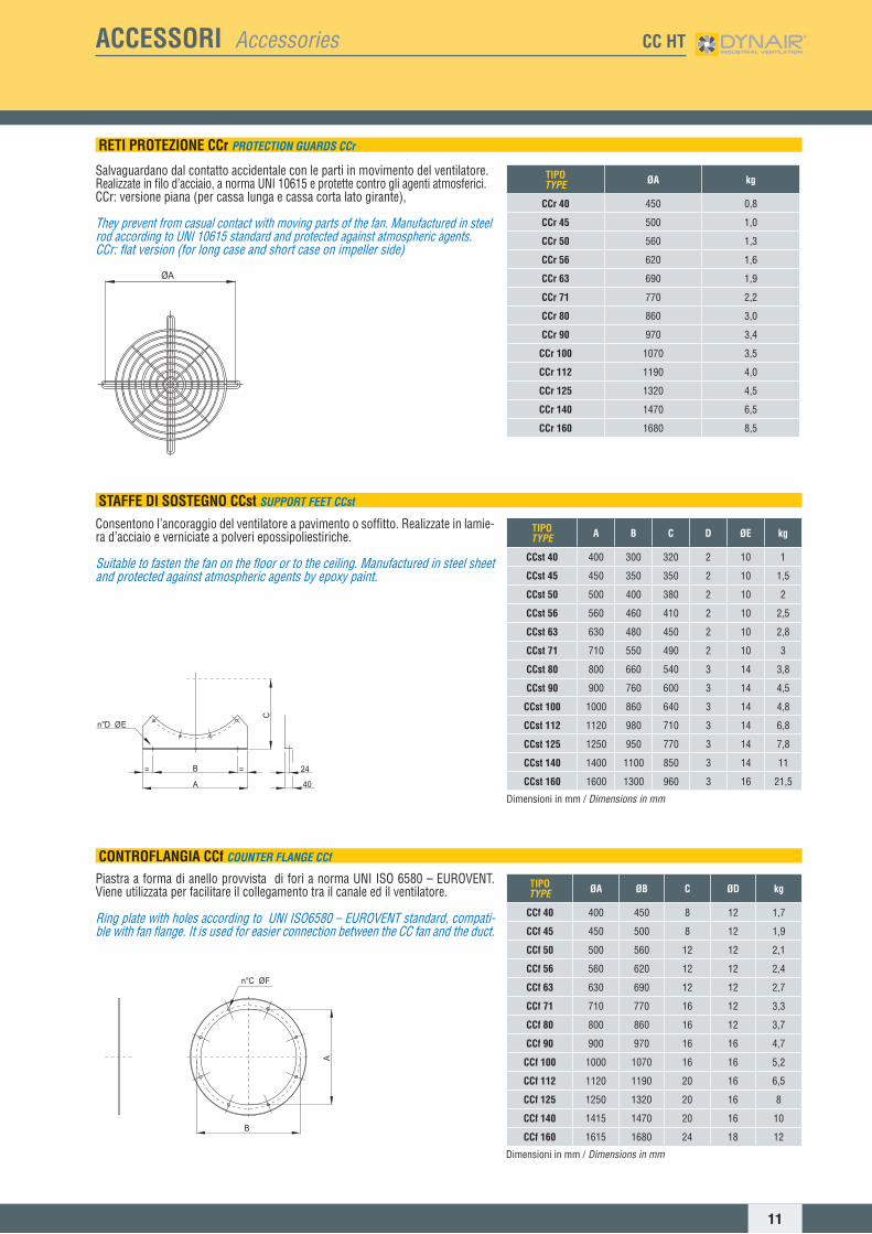
TIPOTYPE ØA kg
CCr 40 450 0,8
CCr 45 500 1,0
CCr 50 560 1,3
CCr 56 620 1,6
CCr 63 690 1,9
CCr 71 770 2,2
CCr 80 860 3,0
CCr 90 970 3,4
CCr 100 1070 3,5
CCr 112 1190 4,0
CCr 125 1320 4,5
CCr 140 1470 6,5
CCr 160 1680 8,5
TIPOTYPE A B C D ØE kg
CCst 40 400 300 320 2 10 1
CCst 45 450 350 350 2 10 1,5
CCst 50 500 400 380 2 10 2
CCst 56 560 460 410 2 10 2,5
CCst 63 630 480 450 2 10 2,8
CCst 71 710 550 490 2 10 3
CCst 80 800 660 540 3 14 3,8
CCst 90 900 760 600 3 14 4,5
CCst 100 1000 860 640 3 14 4,8
CCst 112 1120 980 710 3 14 6,8
CCst 125 1250 950 770 3 14 7,8
CCst 140 1400 1100 850 3 14 11
CCst 160 1600 1300 960 3 16 21,5
Dimensioni in mm / Dimensionsinmm
TIPOTYPE ØA ØB C ØD kg
CCf 40 400 450 8 12 1,7
CCf 45 450 500 8 12 1,9
CCf 50 500 560 12 12 2,1
CCf 56 560 620 12 12 2,4
CCf 63 630 690 12 12 2,7
CCf 71 710 770 16 12 3,3
CCf 80 800 860 16 12 3,7
CCf 90 900 970 16 16 4,7
CCf 100 1000 1070 16 16 5,2
CCf 112 1120 1190 20 16 6,5
CCf 125 1250 1320 20 16 8
CCf 140 1415 1470 20 16 10
CCf 160 1615 1680 24 18 12
Dimensioni in mm / Dimensionsinmm
RETI PROTEZIONE CCr PROTECTION guARDS CCr
Salvaguardano dal contatto accidentale con le parti in movimento del ventilatore.Realizzate in filo d’acciaio, a norma UNI 10615 e protette contro gli agenti atmosferici.CCr: versione piana (per cassa lunga e cassa corta lato girante),
They prevent from casual contact with moving parts of the fan. Manufactured in steel rod according to UNI 10615 standard and protected against atmospheric agents.CCr: flat version (for long case and short case on impeller side)
STAFFE DI SOSTEGNO CCst SuPPORT FEET CCst
Consentono l’ancoraggio del ventilatore a pavimento o soffitto. Realizzate in lamie-ra d’acciaio e verniciate a polveri epossipoliestiriche.
Suitable to fasten the fan on the floor or to the ceiling. Manufactured in steel sheet and protected against atmospheric agents by epoxy paint.
CONTROFLANGIA CCf COuNTER FLANgE CCf
Piastra a forma di anello provvista di fori a norma UNI ISO 6580 – EUROVENT. Viene utilizzata per facilitare il collegamento tra il canale ed il ventilatore.
Ring plate with holes according to UNI ISO6580 – EUROVENT standard, compati-ble with fan flange. It is used for easier connection between the CC fan and the duct.
ACCESSORI Accessories CC HT
12
TIPOTYPE ØA ØB C ØD kg
CCfc 40 400 450 8 12 1,7
CCfc 45 450 500 8 12 2
CCfc 50 500 560 12 12 2,2
CCfc 56 560 620 12 12 2,5
CCfc 63 630 690 12 12 2,9
CCfc 71 710 770 16 12 3,3
CCfc 80 800 860 16 12 3,8
CCfc 90 900 970 16 16 4,2
CCfc 100 1000 1070 16 16 5
CCfc 112 1120 1190 20 16 5,8
CCfc 125 1250 1320 20 16 6,5
CCfc 140 1415 1470 20 16 10
CCfc 160 1615 1680 24 18 12
Dimensioni in mm / Dimensionsinmm
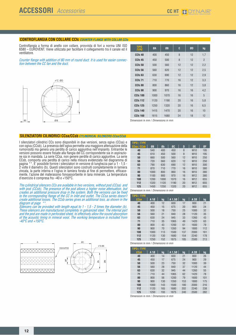
TIPO / TYPECCsa / CCsb ØB Øb ØC D ØE ØF
40 540 400 450 8 M10 19545 610 450 500 8 M10 19550 660 500 560 12 M10 25056 720 560 620 12 M10 25063 790 630 690 12 M10 30071 870 710 770 16 M10 38080 1000 800 860 16 M10 38090 1100 900 970 16 M12 380100 1200 1000 1070 16 M12 655112 1320 1120 1190 20 M12 655125 1450 1250 1320 20 M12 655
Dimensioni in mm / Dimensionsinmm
TIPO / TYPECCsa A 1Ø kg A 1,5Ø kg A 2Ø kg
40 400 12 600 17 800 2145 450 15 675 20 900 2450 500 18 750 25 1000 3256 560 21 840 28 1120 3563 630 24 945 33 1260 4371 710 35 1065 49 1420 6380 800 43 1200 61 1600 7990 900 70 1350 94 1800 112100 1000 113 1500 137 2000 161112 1120 130 1680 154 2240 178125 1250 152 1875 185 2500 213
Dimensioni in mm / Dimensionsinmm
TIPO / TYPECCsb A 1Ø kg A 1,5Ø kg A 2Ø kg
40 400 14 600 21 800 2645 450 17 675 24 900 2950 500 23 750 32 1000 3956 560 28 840 37 1120 4463 630 32 945 44 1260 5571 710 44 1065 62 1420 7880 800 56 1200 79 1600 10190 900 130 1350 153 1800 175100 1000 143 1500 180 2000 216112 1120 165 1680 202 2240 238125 1250 193 1875 240 2500 282
Dimensioni in mm / Dimensionsinmm
CONTROFLANGIA CON COLLARE CCfc COuNTER FLANgE wITH COLLAR CCfc
Controflangia a forma di anello con collare, provvista di fori a norma UNI ISO 6580 – EUROVENT. Viene utilizzata per facilitare il collegamento tra il canale ed il ventilatore.
Counter flange with addition of 80 mm of round duct. It is used for easier connec-tion between the CC fan and the duct.
SILENZIATORI CILINDRICI CCsa/CCsb CYLINDRICAL SILENCERS CCsa/CCsb
I silenziatori cilindrici CCs sono disponibili in due versioni, senza ogiva (CCsa) e con ogiva (CCsb). La presenza dell’ogiva permette una maggiore attenuazione della rumorosità ma genera una perdita di carico aggiuntiva nell’impianto. Entrambe le versioni possono essere fissate alla flangia del CC corrispondente sia in aspirazio-ne sia in mandata. La serie CCsa, non genere perdite di carico aggiuntive. La serie CCsb, comporta una perdita di carico nella misura evidenziata nel diagramma di pagina **. E’ possibile fornire i silenziatori in versione di lunghezza pari a 1 - 1,5 - 2 volte il diametro (b). Questi silenziatori sono costruiti completamente in lamiera zincata, la parte interna e l’ogiva in lamiera forata al fine di permettere, efficace-mente, l’azione del materassino fonoassorbente in lana minerale. La temperatura d’esercizio è compresa fra –40 e +150°C.
The cylindrical silencers CCs are available in two versions, without pod (CCsa) and with pod (CCsb). The presence of the pod allows a higher noise attenuation, but creates an additional pressure drop in the system. Both the versions can be fixed to the corresponding flange of the CC in inlet and outlet. The CCsa series doesn’t create additional losses. The CCsb series gives an additional loss, as shown in the diagram at page **. Silencers can be provided with length equal to 1 - 1,5 - 2 times the diameter (b). These silencers are manufactured completely in galvanized steel. The internal part and the pod are made in perforated sheet, to effectively allow the sound absorption of the acoustic lining in mineral wool. The working temperature is included from -40°C and +150°C.
ACCESSORI Accessories CC HT
13
ACCESSORI Accessories CC HT
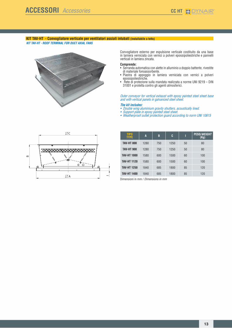
KIT TAV-HT - Convogliatore verticale per ventilatori assiali intubati (installabile a tetto)KIT TAV-HT - ROOF TERMINAL FOR DuCT AxIAL FANS
Convogliatore esterno per espulsione verticale costituito da una base in lamiera verniciata con vernici a polveri epossipoliestiriche e pannelli verticali in lamiera zincata.
Comprende:• Serranda automatica con alette in alluminio a doppio battente, rivestite
di materiale fonoassorbente.• Piastra di appoggio in lamiera verniciata con vernici a polveri
epossipoliestiriche.• Rete di protezione sulla mandata realizzata a norme UNI 9219 – DIN
31001 e protetta contro gli agenti atmosferici.
Outer conveyor for vertical exhaust with epoxy painted steel sheet base and with vertical panels in galvanized steel sheet.The kit includes:• Double wing aluminium gravity shutters, acoustically lined.• Support plate in epoxy painted steel sheet.• Weatherproof outlet protection guard according to norm UNI 10615
B
A I
C TIPOTYPE A B C I PESO/wEIgHT
(Kg)
TAV-HT 800 1280 750 1250 50 80
TAV-HT 900 1280 750 1250 50 80
TAV-HT 1000 1580 600 1500 60 100
TAV-HT 1120 1580 600 1500 60 100
TAV-HT 1250 1840 685 1800 85 120
TAV-HT 1400 1840 685 1800 85 120
Dimensioni in mm / Dimensionsinmm