Embed Size (px)
Citation preview

FastMigX 350, X 450
Operating manual
Brugsanvisning
Gebrauchsanweisung
Manual de instrucciones
Käyttöohje
Manuel d’utilisation
Manuale d’uso
Gebruiksaanwijzing
Bruksanvisning
Instrukcja obsługi
Manual de utilização
Инструкции по эксплуатации
Bruksanvisning
操作手册
EN
DA
DE
ES
FI
FR
IT
NL
NO
PL
PT
RU
SV
ZH
CHANNEL
MENU
X37


OPERATING MANUALEnglish
FastMig X 350, X 4502
EN
CONTENTS
1. Introduction ....................................................................................................... 31.1 General . . . . . . . . . . . . . . . . . . . . . . . . . . . . . . . . . . . . . . . . . . . . . . . . . . . . . . . . . . . . . . . . . . . . . . . . . . . . . . . . . . . . . . . . . . . . . . . . . . . . . . . . . . . . . . . . . . . . . . . . . . . . . . . . . . . . . . . 31.2 About FastMig X 350 and X 450 . . . . . . . . . . . . . . . . . . . . . . . . . . . . . . . . . . . . . . . . . . . . . . . . . . . . . . . . . . . . . . . . . . . . . . . . . . . . . . . . . . . . . . . . 3
2. Installation.......................................................................................................... 42.1 Before use . . . . . . . . . . . . . . . . . . . . . . . . . . . . . . . . . . . . . . . . . . . . . . . . . . . . . . . . . . . . . . . . . . . . . . . . . . . . . . . . . . . . . . . . . . . . . . . . . . . . . . . . . . . . . . . . . . . . . . . . . . . . . . . . . . 42.2 Distribution network . . . . . . . . . . . . . . . . . . . . . . . . . . . . . . . . . . . . . . . . . . . . . . . . . . . . . . . . . . . . . . . . . . . . . . . . . . . . . . . . . . . . . . . . . . . . . . . . . . . . . . . . . . . . . 42.3 Machine introduction . . . . . . . . . . . . . . . . . . . . . . . . . . . . . . . . . . . . . . . . . . . . . . . . . . . . . . . . . . . . . . . . . . . . . . . . . . . . . . . . . . . . . . . . . . . . . . . . . . . . . . . . . . . 52.4 Positioning of the machine . . . . . . . . . . . . . . . . . . . . . . . . . . . . . . . . . . . . . . . . . . . . . . . . . . . . . . . . . . . . . . . . . . . . . . . . . . . . . . . . . . . . . . . . . . . . . . . . 52.5 Connecting cables . . . . . . . . . . . . . . . . . . . . . . . . . . . . . . . . . . . . . . . . . . . . . . . . . . . . . . . . . . . . . . . . . . . . . . . . . . . . . . . . . . . . . . . . . . . . . . . . . . . . . . . . . . . . . . . . . 6
2.5.1 Liquid-cooled system: FastMig X 350 or X 450 + WFX + Cool X . . . . . . . . . . . . . . . . . . . . . . . . . . . . . . . . . . . 62.5.2 Air-cooled system: FastMig X 350 or X 450 + WFX . . . . . . . . . . . . . . . . . . . . . . . . . . . . . . . . . . . . . . . . . . . . . . . . . . . . . . . . 72.5.3 Cable positions for multiple machine configurations . . . . . . . . . . . . . . . . . . . . . . . . . . . . . . . . . . . . . . . . . . . . . . . . . . . 82.5.4 Connecting to mains power . . . . . . . . . . . . . . . . . . . . . . . . . . . . . . . . . . . . . . . . . . . . . . . . . . . . . . . . . . . . . . . . . . . . . . . . . . . . . . . . . . . . . . . . . . . 82.5.5 Cables . . . . . . . . . . . . . . . . . . . . . . . . . . . . . . . . . . . . . . . . . . . . . . . . . . . . . . . . . . . . . . . . . . . . . . . . . . . . . . . . . . . . . . . . . . . . . . . . . . . . . . . . . . . . . . . . . . . . . . . . . . . . . . . 92.5.6 Interconnection with wire feeder . . . . . . . . . . . . . . . . . . . . . . . . . . . . . . . . . . . . . . . . . . . . . . . . . . . . . . . . . . . . . . . . . . . . . . . . . . . . . . . . . . . 9
3. Operation control .......................................................................................... 103.1 Main switch I/O . . . . . . . . . . . . . . . . . . . . . . . . . . . . . . . . . . . . . . . . . . . . . . . . . . . . . . . . . . . . . . . . . . . . . . . . . . . . . . . . . . . . . . . . . . . . . . . . . . . . . . . . . . . . . . . . . . . . . 103.2 Pilot lamps . . . . . . . . . . . . . . . . . . . . . . . . . . . . . . . . . . . . . . . . . . . . . . . . . . . . . . . . . . . . . . . . . . . . . . . . . . . . . . . . . . . . . . . . . . . . . . . . . . . . . . . . . . . . . . . . . . . . . . . . . . . . . . . 103.3 Operation of cooling fan . . . . . . . . . . . . . . . . . . . . . . . . . . . . . . . . . . . . . . . . . . . . . . . . . . . . . . . . . . . . . . . . . . . . . . . . . . . . . . . . . . . . . . . . . . . . . . . . . . . 103.4 Manual Metal Arc Welding . . . . . . . . . . . . . . . . . . . . . . . . . . . . . . . . . . . . . . . . . . . . . . . . . . . . . . . . . . . . . . . . . . . . . . . . . . . . . . . . . . . . . . . . . . . . . . . . 103.5 Using external devices with CC and CV modes . . . . . . . . . . . . . . . . . . . . . . . . . . . . . . . . . . . . . . . . . . . . . . . . . . . . . . . . 10
4. Control panel X 37 ......................................................................................... 114.1 Layout and button functions . . . . . . . . . . . . . . . . . . . . . . . . . . . . . . . . . . . . . . . . . . . . . . . . . . . . . . . . . . . . . . . . . . . . . . . . . . . . . . . . . . . . . . . . . . . 114.2 Using the menus . . . . . . . . . . . . . . . . . . . . . . . . . . . . . . . . . . . . . . . . . . . . . . . . . . . . . . . . . . . . . . . . . . . . . . . . . . . . . . . . . . . . . . . . . . . . . . . . . . . . . . . . . . . . . . . . . . . 13
4.2.1 Selecting the interface language . . . . . . . . . . . . . . . . . . . . . . . . . . . . . . . . . . . . . . . . . . . . . . . . . . . . . . . . . . . . . . . . . . . . . . . . . . . . . . . . . 134.2.2 About memory channels . . . . . . . . . . . . . . . . . . . . . . . . . . . . . . . . . . . . . . . . . . . . . . . . . . . . . . . . . . . . . . . . . . . . . . . . . . . . . . . . . . . . . . . . . . . . . . 134.2.3 Creating the first memory channel . . . . . . . . . . . . . . . . . . . . . . . . . . . . . . . . . . . . . . . . . . . . . . . . . . . . . . . . . . . . . . . . . . . . . . . . . . . . . . 134.2.4 Creating the first MMA/CC/CV memory channel . . . . . . . . . . . . . . . . . . . . . . . . . . . . . . . . . . . . . . . . . . . . . . . . . . . . . . . . 144.2.5 Creating and modifying memory channels . . . . . . . . . . . . . . . . . . . . . . . . . . . . . . . . . . . . . . . . . . . . . . . . . . . . . . . . . . . . . . . . . 14
4.3 Welding parameters . . . . . . . . . . . . . . . . . . . . . . . . . . . . . . . . . . . . . . . . . . . . . . . . . . . . . . . . . . . . . . . . . . . . . . . . . . . . . . . . . . . . . . . . . . . . . . . . . . . . . . . . . . . . 144.4 Welding functions . . . . . . . . . . . . . . . . . . . . . . . . . . . . . . . . . . . . . . . . . . . . . . . . . . . . . . . . . . . . . . . . . . . . . . . . . . . . . . . . . . . . . . . . . . . . . . . . . . . . . . . . . . . . . . . . 174.5 Arc voltage display . . . . . . . . . . . . . . . . . . . . . . . . . . . . . . . . . . . . . . . . . . . . . . . . . . . . . . . . . . . . . . . . . . . . . . . . . . . . . . . . . . . . . . . . . . . . . . . . . . . . . . . . . . . . . . . 214.6 Welding software delivery profile . . . . . . . . . . . . . . . . . . . . . . . . . . . . . . . . . . . . . . . . . . . . . . . . . . . . . . . . . . . . . . . . . . . . . . . . . . . . . . . . . . 22
5. Troubleshooting............................................................................................. 22
6. Operation disturbances ............................................................................... 24
7. Maintenance .................................................................................................... 257.1 Daily maintenance . . . . . . . . . . . . . . . . . . . . . . . . . . . . . . . . . . . . . . . . . . . . . . . . . . . . . . . . . . . . . . . . . . . . . . . . . . . . . . . . . . . . . . . . . . . . . . . . . . . . . . . . . . . . . . . 257.2 Periodic maintenance . . . . . . . . . . . . . . . . . . . . . . . . . . . . . . . . . . . . . . . . . . . . . . . . . . . . . . . . . . . . . . . . . . . . . . . . . . . . . . . . . . . . . . . . . . . . . . . . . . . . . . . . . 257.3 Service Workshop maintenance . . . . . . . . . . . . . . . . . . . . . . . . . . . . . . . . . . . . . . . . . . . . . . . . . . . . . . . . . . . . . . . . . . . . . . . . . . . . . . . . . . . . . 26
8. Disposal of the machine .............................................................................. 26
9. Ordering codes ............................................................................................... 27
10. Technical data ................................................................................................. 29
3© Kemppi Oy / 1520
EN
1. INTRODUCTION
1.1 GeneralCongratulations on choosing the FastMig X welding equipment. Used correctly, Kemppi products can significantly increase the productivity of your welding, and provide years of economical service. This operating manual contains important information on the use, maintenance and safety of your Kemppi product. The technical specifications of the equipment can be found at the end of the manual. Please read the operating manual and the safety instructions booklet carefully before using the equipment for the first time. For your own safety and that of your working environment, pay particular attention to the safety instructions in the manual.For more information on Kemppi products, contact Kemppi Oy, consult an authorised Kemppi dealer, or visit the Kemppi web site at www.kemppi.com.The specifications presented in this manual are subject to change without prior notice.
Important notesItems in the manual that require particular attention in order to minimise damage and personal harm are indicated with the ’NOTE!’ notation. Read these sections carefully and follow their instructions.
DisclaimerWhile every effort has been made to ensure that the information contained in this guide is accurate and complete, no liability can be accepted for any errors or omissions. Kemppi reserves the right to change the specification of the product described at any time without prior notice. Do not copy, record, reproduce or transmit the contents of this guide without prior written permission from Kemppi.
1.2 About FastMig X 350 and X 450FastMig X 350 and X 450 are multi-purpose welding power sources designed for demanding professional use. They are suitable for synergic pulsed MIG/MAG, synergic 1-MIG and basic MIG/MAG welding, as well as the modified WiseRoot+™ and WiseThin+™ processes. They can also be used as a welding power source for MMA welding. TIG welding is also available when connected to MasterTig LT 250. Control panel X 37 is included in the delivery for selecting, setting and managing the welding system prior to and during system use. FastMig X 350 and X 450 offer a multi-process solution for a wide range of welding applications. Various cable options, welding software options, remote control units including tablet computer based ARC Mobile Control (adapter included with WFX 200 AMC and 300 AMC wire feeders) and other accessories are available for this product. Please see the list at the end of this manual.
FastMig X 350, X 4504
EN
2. INSTALLATION
2.1 Before useThe product is packed in specially designed transport cartons. However, before use always make sure the products have not been damaged during transportation.Check also that you have received the components you ordered and the corresponding instruction manuals. Product packaging material is recyclable.
NOTE! When moving the welding machine, always lift it from the handle, never pull it from the welding gun or other cables.
Operating environmentThis machine is suitable for both indoor and outdoor use. Always make sure that the air flow to the machine is unrestricted. The recommended operating temperature range is –20…+40 °C.Please ensure you read the safety instructions concerning operating environments supplied in this manual.
2.2 Distribution networkAll regular electrical devices without special circuits generate harmonic currents into distribution network. High rates of harmonic current may cause losses and disturbance to some equipment.
FastMig X 350 and X 450This equipment complies with IEC 61000-3-12 provided that the short-circuit power Ssc is greater than or equal to 5.5 MVA at the interface point between the user’s supply and the public suply network. It is the responsibility of the installer or user of the equipment to ensure, by consultation with the distribution network operator if necessary, that the equipment is connected only to a supply with a short-circuit power Ssc greater than or equal to 5.5 MVA.
5© Kemppi Oy / 1520
EN
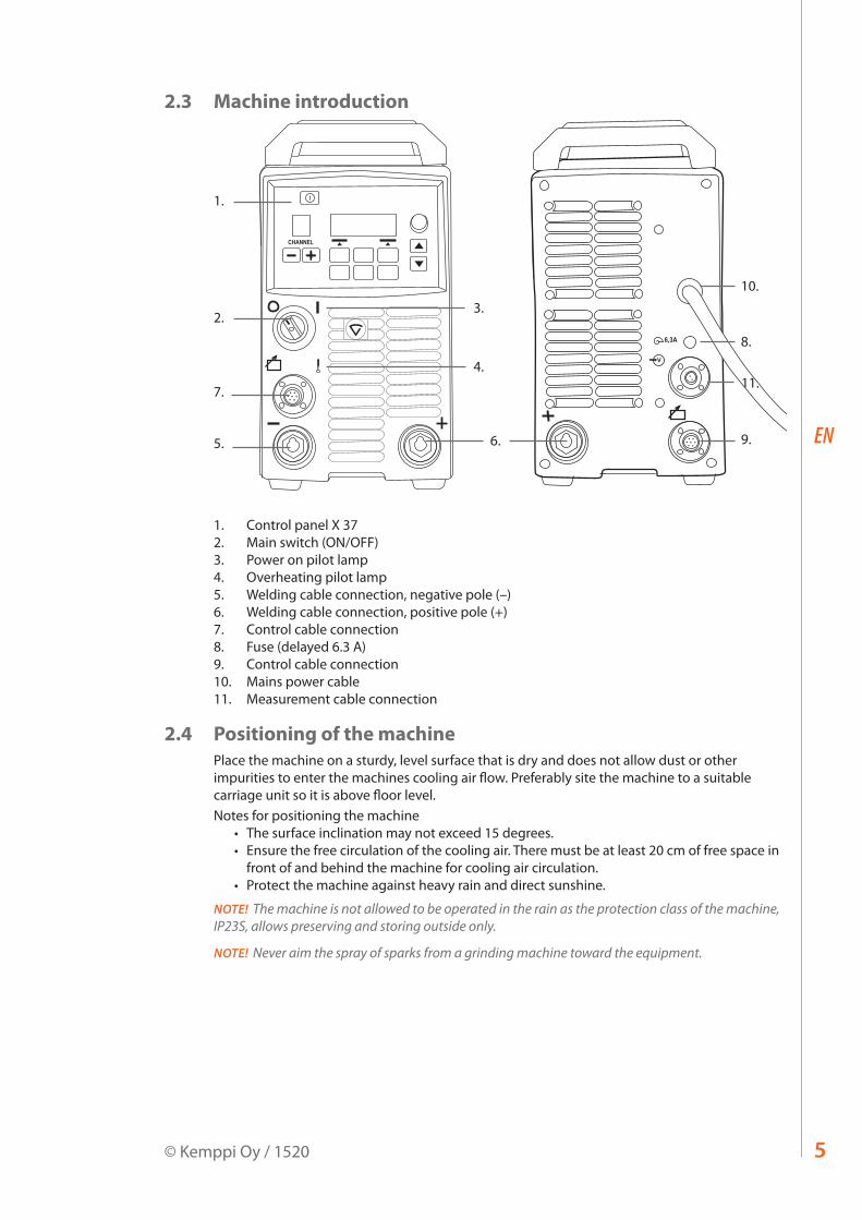
2.3 Machine introduction
CHANNEL
V
6,3A
1.
2.3.
4.
8.
10.
5.
7.
9.6.
11.
1. Control panel X 372. Main switch (ON/OFF)3. Power on pilot lamp4. Overheating pilot lamp5. Welding cable connection, negative pole (–)6. Welding cable connection, positive pole (+)7. Control cable connection8. Fuse (delayed 6.3 A)9. Control cable connection10. Mains power cable11. Measurement cable connection
2.4 Positioning of the machinePlace the machine on a sturdy, level surface that is dry and does not allow dust or other impurities to enter the machines cooling air flow. Preferably site the machine to a suitable carriage unit so it is above floor level.Notes for positioning the machine
• The surface inclination may not exceed 15 degrees.• Ensure the free circulation of the cooling air. There must be at least 20 cm of free space in
front of and behind the machine for cooling air circulation.• Protect the machine against heavy rain and direct sunshine.
NOTE! The machine is not allowed to be operated in the rain as the protection class of the machine, IP23S, allows preserving and storing outside only.
NOTE! Never aim the spray of sparks from a grinding machine toward the equipment.
FastMig X 350, X 4506
EN
2.5 Connecting cablesNOTE! Always check before use that the mains cable, earth return cable and its clamp, interconnection cable and shielding gas hose are in a serviceable condition. Ensure that connectors are correctly fastened. Lose connectors can impair welding performance and damage connectors.
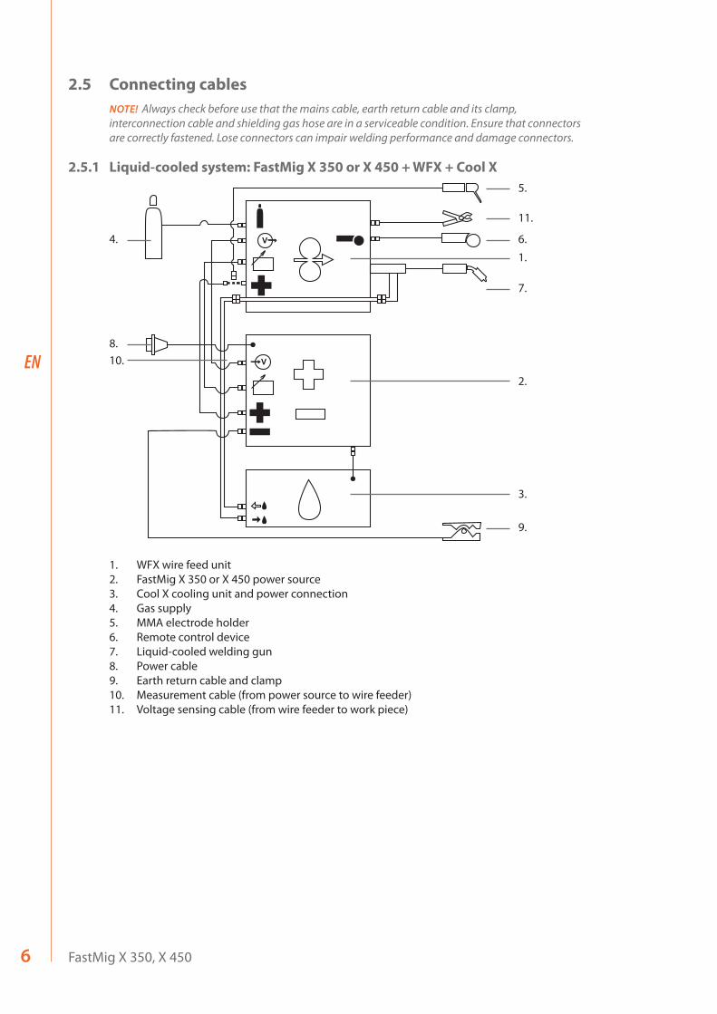
2.5.1 Liquid-cooled system: FastMig X 350 or X 450 + WFX + Cool X
1.
4.
8.10.
2.
3.
9.
5.
6.
11.
7.
V
V
1. WFX wire feed unit2. FastMig X 350 or X 450 power source3. Cool X cooling unit and power connection4. Gas supply5. MMA electrode holder6. Remote control device7. Liquid-cooled welding gun8. Power cable9. Earth return cable and clamp10. Measurement cable (from power source to wire feeder)11. Voltage sensing cable (from wire feeder to work piece)
7© Kemppi Oy / 1520
EN
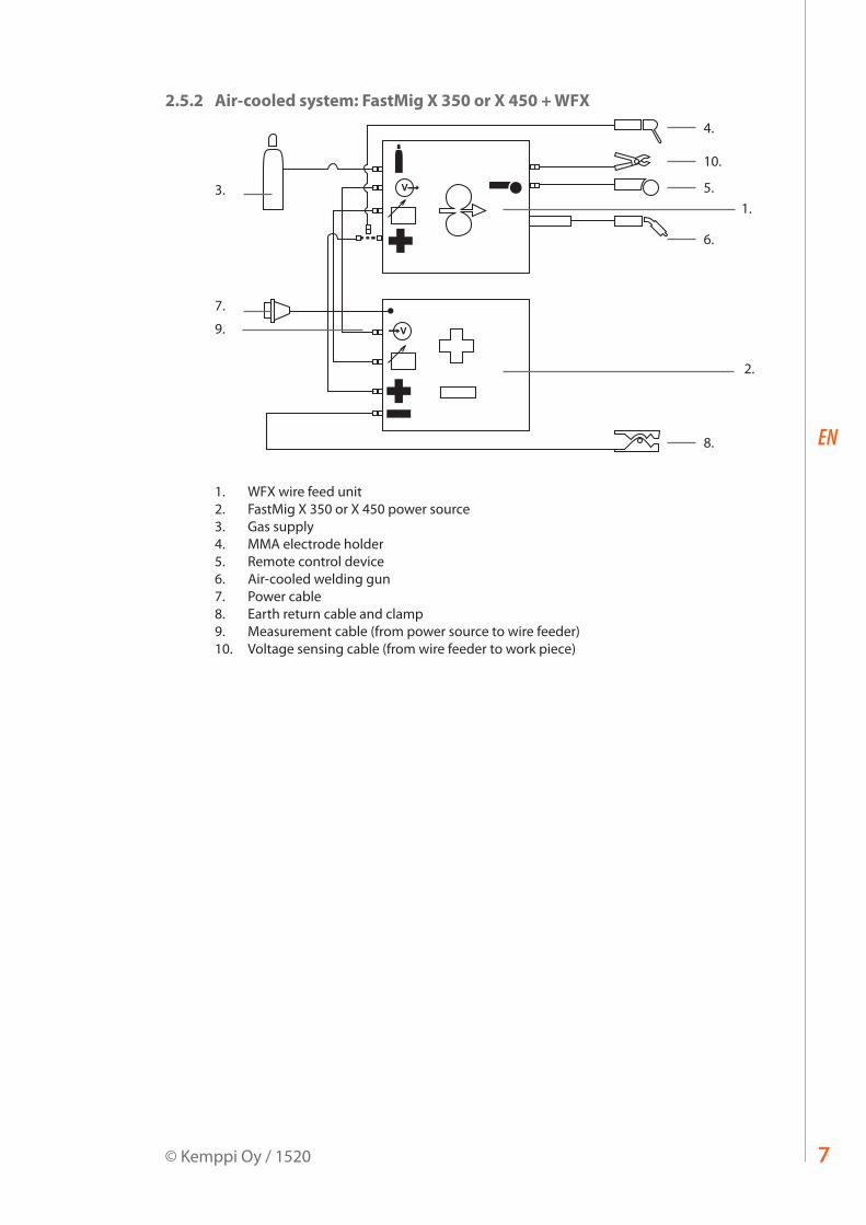
2.5.2 Air-cooled system: FastMig X 350 or X 450 + WFX
1.
4.
5.
10.
6.
8.
2.
3.
7.
9. V
V
1. WFX wire feed unit2. FastMig X 350 or X 450 power source3. Gas supply4. MMA electrode holder5. Remote control device6. Air-cooled welding gun7. Power cable8. Earth return cable and clamp9. Measurement cable (from power source to wire feeder)10. Voltage sensing cable (from wire feeder to work piece)
FastMig X 350, X 4508
EN
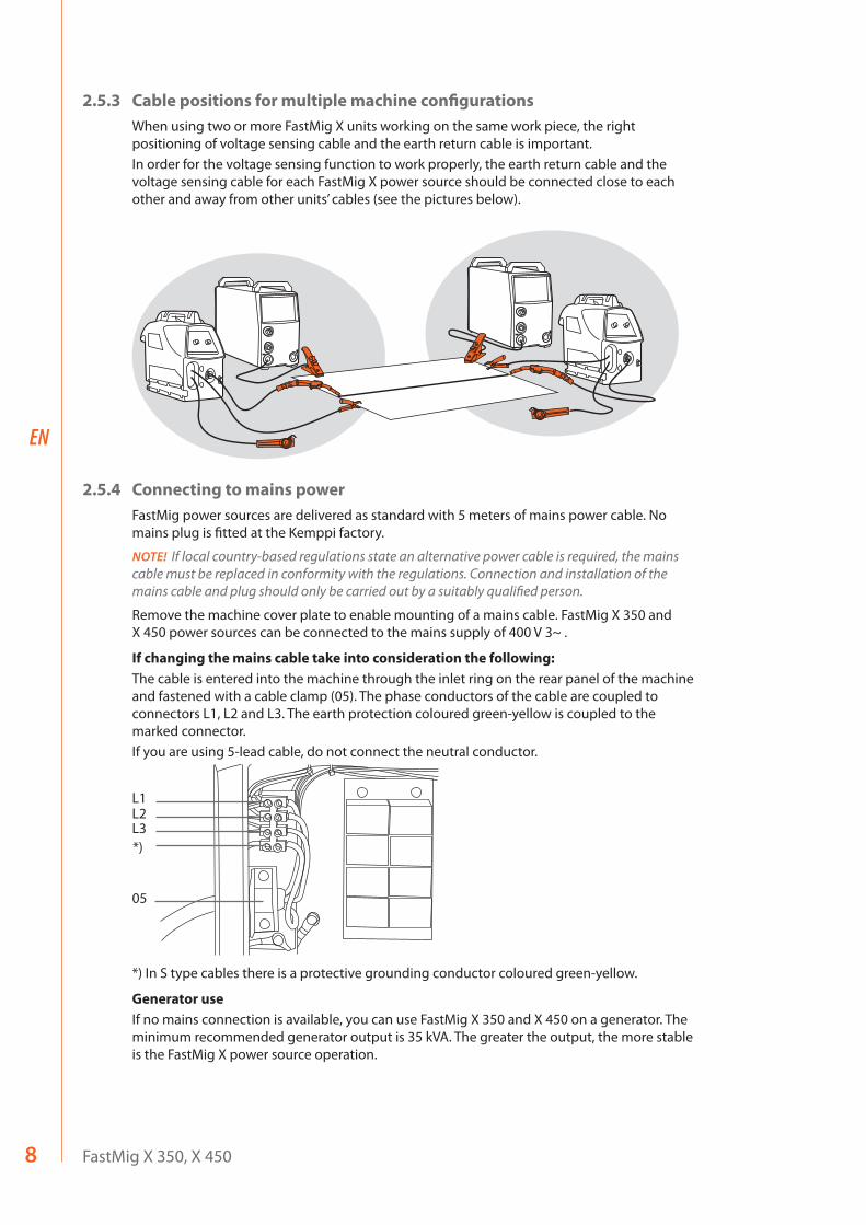
2.5.3 Cable positions for multiple machine configurationsWhen using two or more FastMig X units working on the same work piece, the right positioning of voltage sensing cable and the earth return cable is important.In order for the voltage sensing function to work properly, the earth return cable and the voltage sensing cable for each FastMig X power source should be connected close to each other and away from other units’ cables (see the pictures below).
2.5.4 Connecting to mains powerFastMig power sources are delivered as standard with 5 meters of mains power cable. No mains plug is fitted at the Kemppi factory.
NOTE! If local country-based regulations state an alternative power cable is required, the mains cable must be replaced in conformity with the regulations. Connection and installation of the mains cable and plug should only be carried out by a suitably qualified person.
Remove the machine cover plate to enable mounting of a mains cable. FastMig X 350 and X 450 power sources can be connected to the mains supply of 400 V 3~ .
If changing the mains cable take into consideration the following:The cable is entered into the machine through the inlet ring on the rear panel of the machine and fastened with a cable clamp (05). The phase conductors of the cable are coupled to connectors L1, L2 and L3. The earth protection coloured green-yellow is coupled to the marked connector.If you are using 5-lead cable, do not connect the neutral conductor.
05
*)L3L2L1
*) In S type cables there is a protective grounding conductor coloured green-yellow.
Generator useIf no mains connection is available, you can use FastMig X 350 and X 450 on a generator. The minimum recommended generator output is 35 kVA. The greater the output, the more stable is the FastMig X power source operation.

9© Kemppi Oy / 1520
EN
2.5.5 CablesKemppi always recommend the use of high quality copper cables with a suitable cross-sectional area. Cable size should be selected depending on the intended welding application.50 mm² copper cables may be used for low duty work in basic or synergic 1-MIG. However, using pulsed MIG/MAG process, longer cables, or higher welding power increase the voltage loss, and therefore smaller cross sectional interconnection cables and earth return cables will restrict the welding performance of your machine.
Recommended cross-sectional area of FastMig X power source cables: 70 – 90 mm². The enclosed table shows typical load capacities and voltage loss values of rubber insulated copper cables for duty cycles 100%, 60% and 30%, when ambient temperature is 25 °C and the cable temperature is 85 °C.
Cable size 100 % 60 % 30 % Voltage loss / 10 m50 mm² 285 A 370 A 520 A 0.35 V / 100 A
70 mm² 355 A 460 A 650 A 0.25 V / 100 A
95 mm² 430 A 560 A 790 A 0.18 V / 100 A
Do not overload the cables due to voltage losses and heating.
NOTE! Always check the serviceability of the earth return cable and clamp. Ensure the metal surface to which the cable is connected is clean from metal oxide or paint. Check the connector to the power source is fastened correctly.
2.5.6 Interconnection with wire feederKemppi provide a choice of interconnection cable sets for different environments. Only materials that meet the demands of Kemppi's international markets are used in their construction.Used correctly, Kemppi cable sets ensure high welding performance and serviceability.Before use, always ensure the cable set is in good condition and that connectors are correctly fastened. Loose connections reduce welding performance and may result in damage to connectors due to heating effects. For correct connection and configuration of cable sets, please refer to schematic drawings in section 2.5 of this manual.
NOTE! FastMig X 350 and X 450 power sources are designed to be used with WFX wire feed units.
FastMig X 350, X 45010
EN
3. OPERATION CONTROL
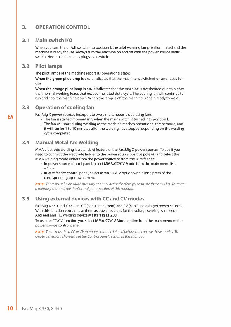
3.1 Main switch I/OWhen you turn the on/off switch into position I, the pilot warning lamp is illuminated and the machine is ready for use. Always turn the machine on and off with the power source mains switch. Never use the mains plugs as a switch.
3.2 Pilot lampsThe pilot lamps of the machine report its operational state:When the green pilot lamp is on, it indicates that the machine is switched on and ready for use.When the orange pilot lamp is on, it indicates that the machine is overheated due to higher than normal working loads that exceed the rated duty cycle. The cooling fan will continue to run and cool the machine down. When the lamp is off the machine is again ready to weld.
3.3 Operation of cooling fanFastMig X power sources incorporate two simultaneously operating fans.
• The fan is started momentarily when the main switch is turned into position I.• The fan will start during welding as the machine reaches operational temperature, and
it will run for 1 to 10 minutes after the welding has stopped, depending on the welding cycle completed.
3.4 Manual Metal Arc WeldingMMA electrode welding is a standard feature of the FastMig X power sources. To use it you need to connect the electrode holder to the power source positive pole (+) and select the MMA welding mode either from the power source or from the wire feeder:
• In power source control panel, select MMA/CC/CV Mode from the main menu list. – OR –
• in wire feeder control panel, select MMA/CC/CV option with a long press of the corresponding up-down-arrow.
NOTE! There must be an MMA memory channel defined before you can use these modes. To create a memory channel, see the Control panel section of this manual.
3.5 Using external devices with CC and CV modesFastMig X 350 and X 450 are CC (constant current) and CV (constant voltage) power sources. With this function you can use them as power sources for the voltage sensing wire feeder ArcFeed and TIG welding device MasterTig LT 250. To use the CC/CV function you select MMA/CC/CV Mode option from the main menu of the power source control panel.
NOTE! There must be a CC or CV memory channel defined before you can use these modes. To create a memory channel, see the Control panel section of this manual.
11© Kemppi Oy / 1520
EN
4. CONTROL PANEL X 37
FastMig X power sources feature X 37 control panel with a clear and logical LCD menu display. The menu allows the operator to refine, adapt and manage the arc process and system function before, during and after welding.The following information details control panel layout, button functions, operation and set-up. The menu options and their descriptions are listed for each menu command.
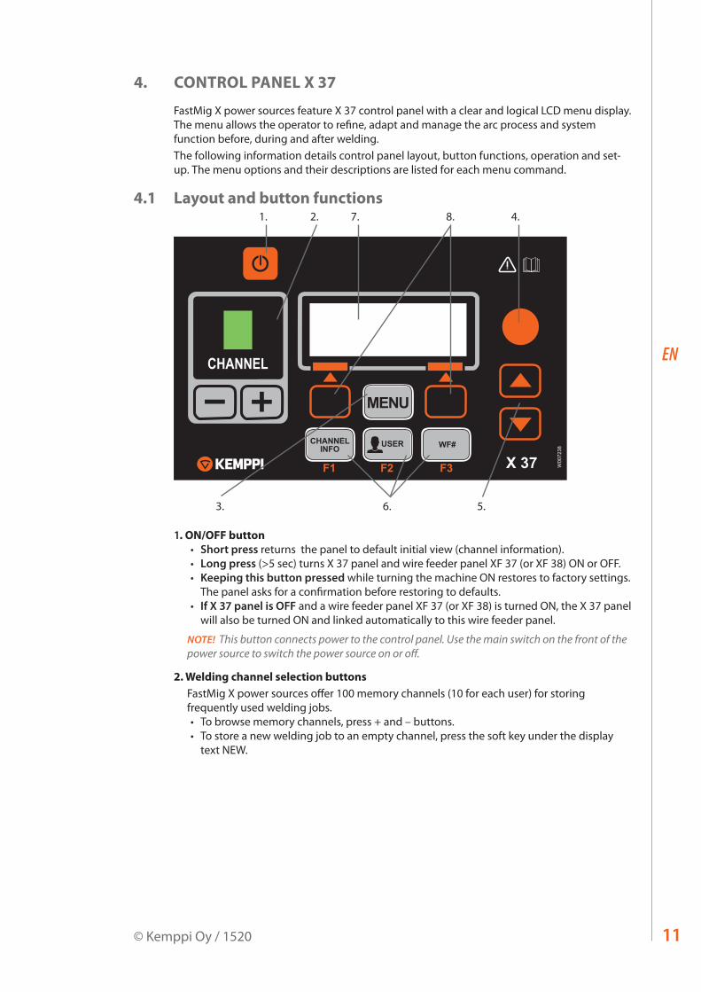
4.1 Layout and button functions
MENU
CHANNELINFO USER WF#
F1 F2 F3 X 37 W00
7238
1. 4.
5.6.
2. 7.
3.
8.
1. ON/OFF button• Short press returns the panel to default initial view (channel information).• Long press (>5 sec) turns X 37 panel and wire feeder panel XF 37 (or XF 38) ON or OFF. • Keeping this button pressed while turning the machine ON restores to factory settings.
The panel asks for a confirmation before restoring to defaults. • If X 37 panel is OFF and a wire feeder panel XF 37 (or XF 38) is turned ON, the X 37 panel
will also be turned ON and linked automatically to this wire feeder panel.
NOTE! This button connects power to the control panel. Use the main switch on the front of the power source to switch the power source on or off.
2. Welding channel selection buttonsFastMig X power sources offer 100 memory channels (10 for each user) for storing frequently used welding jobs. • To browse memory channels, press + and – buttons. • To store a new welding job to an empty channel, press the soft key under the display
text NEW.
FastMig X 350, X 45012
EN
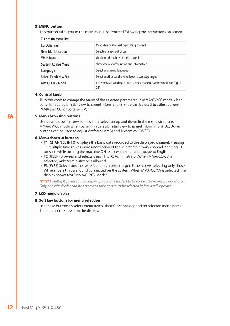
3. MENU buttonThis button takes you to the main menu list. Proceed following the instructions on screen.
X 37 main menu listEdit Channel Make changes to existing welding channel
User Identification Selecti one user out of ten
Weld Data Check out the values of the last weld
System Config Menu Show device configuration and information
Language Select your menu language
Select Feeder (WF#) Select another parallel wire feeder as a setup target
MMA/CC/CV Mode Activate MMA welding, or use CC or CV mode for ArcFeed or MasterTig LT 250
4. Control knobTurn the knob to change the value of the selected parameter. In MMA/CV/CC mode when panel is in default initial view (channel information), knob can be used to adjust current (MMA and CC) or voltage (CV).
5. Menu browsing buttonsUse up and down arrows to move the selection up and down in the menu structure. In MMA/CV/CC mode when panel is in default initial view (channel information), Up/Down buttons can be used to adjust Arcforce (MMA) and Dynamics (CV/CC).
6. Menu shortcut buttons• F1 (CHANNEL INFO) displays the basic data recorded to the displayed channel. Pressing
F1 multiple times gives more information of the selected memory channel. Keeping F1 pressed while turning the machine ON restores the menu language to English.
• F2 (USER) Browses and selects users: 1…10, Administrator. When MMA/CC/CV is selected, only Administrator is allowed.
• F3 (WF#) Selects another wire feeder as a setup target. Panel allows selecting only those WF numbers that are found connected on the system. When MMA/CC/CV is selected, the display shows text ”MMA/CC/CV Mode”.
NOTE! FastMig X power sources allow up to 3 wire feeders to be connected to one power source. Only one wire feeder can be active at a time and must be selected before it will operate.
7. LCD menu display
8. Soft key buttons for menu selectionUse these buttons to select menu items. Their functions depend on selected menu items. The function is shown on the display.
13© Kemppi Oy / 1520
EN
4.2 Using the menus
4.2.1 Selecting the interface languageThe default menu language is English. If you want to select another menu language, do the following: 1. Connect the mains power and switch on the power source at the main switch.
• If this is the initial system activation (if SYSTEM OFF text is in the display), you may need to press and hold the POWER ON button in the to left corner of the X 37 control panel. Hold the button down for 5 seconds.
2. Press the MENU button to display the main menu, which includes 7 menu items. • You can move around in the menu list by pressing the up and down arrow buttons.• As you browse the menu item list, the currently selected item is shown at the bottom
of the display, marked as 1/7, 2/7, 3/7 etc. • The selected menu item is marked with a black arrow-shaped cursor.
3. Browse to the menu item LANGUAGE (5/7) and press the SELECT soft key button.4. Browse to your language and press the SELECT/SAVE soft key button. Your language choice is
now confirmed and will remain selected unless you change it later.
4.2.2 About memory channelsYou can have several setups of welding parameter values for use in various welding applications. These setups (or welding jobs) are stored as memory channels in X 37 control panel. Up to 10 user profiles can be defined in one FastMig X unit, and each of them are assigned up to 10 memory channels. So, you have maximum of 100 memory channels to store your frequently used welding jobs. In addition to them, there are 10 memory channels available for MMA/CC/CV use.To define a new welding job, you need to make the necessary welding parameter selections and then save them to a memory channel of your choice. When you want to use these settings, you simply select the corresponding memory channel number on the power source or wire feeder control panel and start welding. Only the most often used controls are available in the wire feeder control panel, making welding easy and convenient. You can use and update any memory channel, unless it is locked via the four-digit administrator pin code lock.
4.2.3 Creating the first memory channelIf you are starting with a new FastMig X power source that contains no memory channels, follow these steps to create the first memory channel.1. Power on the machine from the main switch. You may need to press the control panel's Power
On button for 5 seconds to activate the X 37 control panel.2. An empty memory channel appears. Press the NEW soft key.3. With Create New selected, press SELECT soft key.4. Select the desired welding process and other welding parameters.
• Use up and down arrow buttons to move around in the menus• Approve selections by pressing the SELECT soft key.
5. When you have made all settings , press SAVE soft key to store the settings in the active memory channel.
FastMig X 350, X 45014
EN
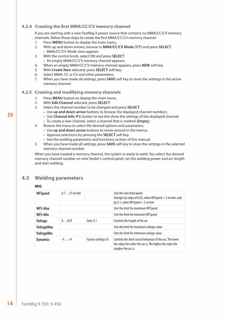
4.2.4 Creating the first MMA/CC/CV memory channelIf you are starting with a new FastMig X power source that contains no MMA/CC/CV memory channels, follow these steps to create the first MMA/CC/CV memory channel.1. Press MENU button to display the main menu.2. With up and down arrows, browse to MMA/CC/CV Mode (7/7) and press SELECT.
• MMA/CC/CV Mode view appears3. With the control knob, select ON and press SELECT.
• An empty MMA/CC/CV memory channel appears. 4. When an empty MMA/CC/CV memory channel appears, press NEW soft key.5. With Create New selected, press SELECT soft key.6. Select MMA, CC or CV and other parameters. 7. When you have made all settings, press SAVE soft key to store the settings in the active
memory channel.
4.2.5 Creating and modifying memory channels1. Press MENU button to display the main menu.2. With Edit Channel selected, press SELECT.3. Select the channel number to be changed and press SELECT.
• Use up and down arrow buttons to browse the displayed channel numbers.• Use Channel Info (F1) button to see the show the settings of the displayed channel.• To create a new channel, select a channel that is marked (Empty).
4. Browse the menu to select the desired options and parameters. • Use up and down arrow buttons to move around in the menus.• Approve selections by pressing the SELECT soft key.• See the welding parameters and functions section of this manual.
5. When you have made all settings, press SAVE soft key to store the settings in the selected memory channel number.
When you have created a memory channel, the system is ready to weld. You select the desired memory channel number on wire feeder's control panel, set the welding power and arc length and start welding.
4.3 Welding parametersMIG
WFSpeed 0.7…25 m/min Sets the wire feed speed.Changes by steps of 0.05, when WFSpeed < 5 m/min, and by 0.1, when WFSpeed > 5 m/min
WFS-Max Sets the limit for maximum WFSpeed
WFS-Min Sets the limit for minimum WFSpeed
Voltage 8…50 V Step: 0.1 Controls the length of the arc
VoltageMax Sets the limit for maximum voltage value
VoltageMin Sets the limit for minimum voltage value
Dynamics -9…+9 Factory setting is 0 Controls the short circuit behaviour of the arc. The lower the value the softer the arc is. The higher the value the rougher the arc is.
15© Kemppi Oy / 1520
EN
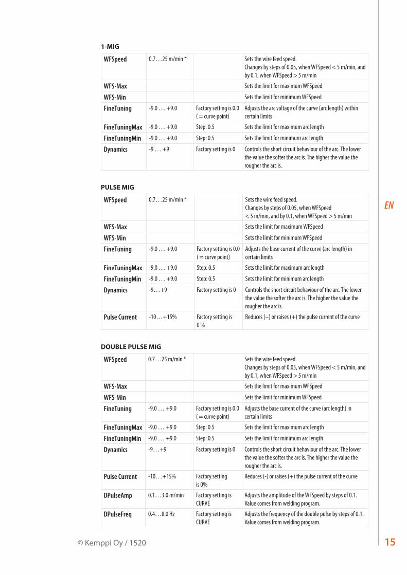
1-MIG
WFSpeed 0.7…25 m/min * Sets the wire feed speed.Changes by steps of 0.05, when WFSpeed < 5 m/min, and by 0.1, when WFSpeed > 5 m/min
WFS-Max Sets the limit for maximum WFSpeed
WFS-Min Sets the limit for minimum WFSpeed
FineTuning -9.0 … +9.0 Factory setting is 0.0 ( = curve point)
Adjusts the arc voltage of the curve (arc length) within certain limits
FineTuningMax -9.0 … +9.0 Step: 0.5 Sets the limit for maximum arc length
FineTuningMin -9.0 … +9.0 Step: 0.5 Sets the limit for minimum arc length
Dynamics -9 … +9 Factory setting is 0 Controls the short circuit behaviour of the arc. The lower the value the softer the arc is. The higher the value the rougher the arc is.
PULSE MIG
WFSpeed 0.7…25 m/min * Sets the wire feed speed.Changes by steps of 0.05, when WFSpeed < 5 m/min, and by 0.1, when WFSpeed > 5 m/min
WFS-Max Sets the limit for maximum WFSpeed
WFS-Min Sets the limit for minimum WFSpeed
FineTuning -9.0 … +9.0 Factory setting is 0.0 ( = curve point)
Adjusts the base current of the curve (arc length) in certain limits
FineTuningMax -9.0 … +9.0 Step: 0.5 Sets the limit for maximum arc length
FineTuningMin -9.0 … +9.0 Step: 0.5 Sets the limit for minimum arc length
Dynamics -9…+9 Factory setting is 0 Controls the short circuit behaviour of the arc. The lower the value the softer the arc is. The higher the value the rougher the arc is.
Pulse Current -10…+15% Factory setting is 0 %
Reduces (–) or raises (+) the pulse current of the curve
DOUBLE PULSE MIG
WFSpeed 0.7…25 m/min * Sets the wire feed speed.Changes by steps of 0.05, when WFSpeed < 5 m/min, and by 0.1, when WFSpeed > 5 m/min
WFS-Max Sets the limit for maximum WFSpeed
WFS-Min Sets the limit for minimum WFSpeed
FineTuning -9.0 … +9.0 Factory setting is 0.0 ( = curve point)
Adjusts the base current of the curve (arc length) in certain limits
FineTuningMax -9.0 … +9.0 Step: 0.5 Sets the limit for maximum arc length
FineTuningMin -9.0 … +9.0 Step: 0.5 Sets the limit for minimum arc length
Dynamics -9…+9 Factory setting is 0 Controls the short circuit behaviour of the arc. The lower the value the softer the arc is. The higher the value the rougher the arc is.
Pulse Current -10…+15% Factory setting is 0%
Reduces (-) or raises (+) the pulse current of the curve
DPulseAmp 0.1…3.0 m/min Factory setting is CURVE
Adjusts the amplitude of the WFSpeed by steps of 0.1. Value comes from welding program.
DPulseFreq 0.4…8.0 Hz Factory setting is CURVE
Adjusts the frequency of the double pulse by steps of 0.1. Value comes from welding program.

FastMig X 350, X 45016
EN
WISEROOT+
WFSpeed 1.5…8.0 m/min * Sets the wire feed speed.Changes by steps of 0.05, when WFSpeed < 5 m/min, and by 0.1, when WFSpeed > 5 m/min
WFS-Max Sets the limit for maximum WFSpeed
WFS-Min Sets the limit for minimum WFSpeed
FineTuning -9.0 … +9.0 Factory setting is 0.0 ( = curve point)
Adjusts the base current of the curve (heat of the arc) within certain limits.
FineTuningMax -9.0 … +9.0 Step: 0.5 Sets the limit for maximum heat of the arc
FineTuningMin -9.0 … +9.0 Step: 0.5 Sets the limit for minimum heat of the arc
* Different welding programs may further restrict the value range.
WISETHIN+
WFSpeed 0.7…25 m/min * Sets the wire feed speed.Changes by steps of 0.05, when WFSpeed < 5 m/min, and by 0.1, when WFSpeed > 5 m/min
WFS-Max Sets the limit for maximum WFSpeed
WFS-Min Sets the limit for minimum WFSpeed
FineTuning -9.0 … +9.0 Factory setting is 0.0 ( = curve point)
Adjusts the arc voltage of the curve (arc length) within certain limits
FineTuningMax -9.0 … +9.0 Step: 0.5 Sets the limit for maximum arc length
FineTuningMin -9.0 … +9.0 Step: 0.5 Sets the limit for minimum arc length
Dynamics -9…+9 Factory setting is 0 Controls the short circuit behaviour of the arc. The lower the value the softer the arc is. The higher the value the rougher the arc is.
MMA PROCESSES
Current 14…350/450 A Welding current
CurrentMax 14…350/450 A Set the limit for maximum current value
CurrentMin 14…350/450 A Set the limit for minimum current value
ArcForce -9…+9 Factory setting is 0 Controls the short circuit behaviour of the arc. The lower the value the softer the arc is. The higher the value the rougher the arc is.
StartPower -9…+9 Factory setting is 0 Adjusts arc ignition
CC PROCESS
Current 10…350/450 A Welding current
CurrentMax 10…350/450 A Set the limit for maximum current value
CurrentMin 10…350/450 A Set the limit for minimum current value
Dynamics -9…+9 Factory setting is 0 Controls the short circuit behaviour of the arc. The lower the value the softer the arc is. The higher the value the rougher the arc is.
StartPower -9…+9 Factory setting is 0 Adjusts arc ignition
17© Kemppi Oy / 1520
EN
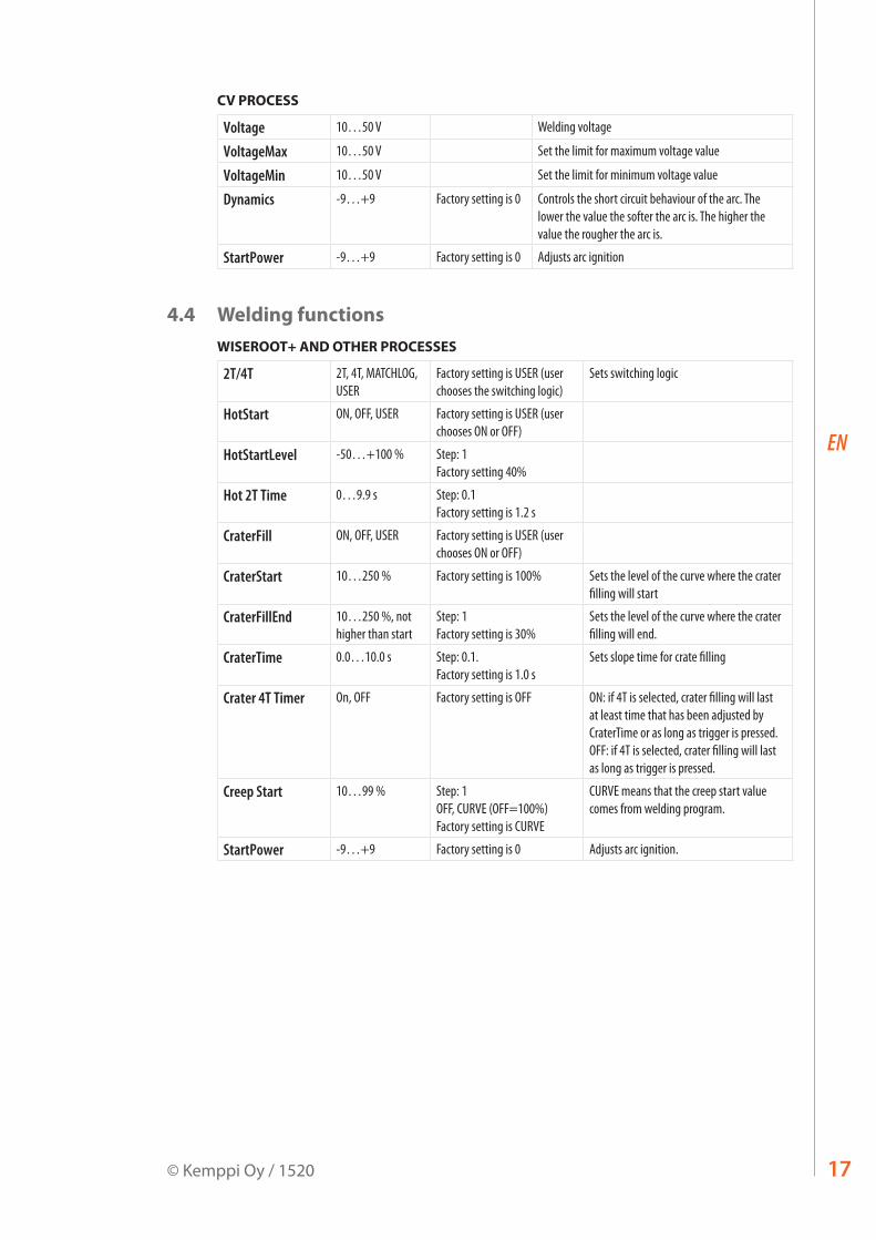
CV PROCESS
Voltage 10…50 V Welding voltage
VoltageMax 10…50 V Set the limit for maximum voltage value
VoltageMin 10…50 V Set the limit for minimum voltage value
Dynamics -9…+9 Factory setting is 0 Controls the short circuit behaviour of the arc. The lower the value the softer the arc is. The higher the value the rougher the arc is.
StartPower -9…+9 Factory setting is 0 Adjusts arc ignition
4.4 Welding functionsWISEROOT+ AND OTHER PROCESSES
2T/4T 2T, 4T, MATCHLOG, USER
Factory setting is USER (user chooses the switching logic)
Sets switching logic
HotStart ON, OFF, USER Factory setting is USER (user chooses ON or OFF)
HotStartLevel -50…+100 % Step: 1 Factory setting 40%
Hot 2T Time 0…9.9 s Step: 0.1 Factory setting is 1.2 s
CraterFill ON, OFF, USER Factory setting is USER (user chooses ON or OFF)
CraterStart 10…250 % Factory setting is 100% Sets the level of the curve where the crater filling will start
CraterFillEnd 10…250 %, not higher than start
Step: 1 Factory setting is 30%
Sets the level of the curve where the crater filling will end.
CraterTime 0.0…10.0 s Step: 0.1. Factory setting is 1.0 s
Sets slope time for crate filling
Crater 4T Timer On, OFF Factory setting is OFF ON: if 4T is selected, crater filling will last at least time that has been adjusted by CraterTime or as long as trigger is pressed. OFF: if 4T is selected, crater filling will last as long as trigger is pressed.
Creep Start 10…99 % Step: 1 OFF, CURVE (OFF=100%) Factory setting is CURVE
CURVE means that the creep start value comes from welding program.
StartPower -9…+9 Factory setting is 0 Adjusts arc ignition.
FastMig X 350, X 45018
EN
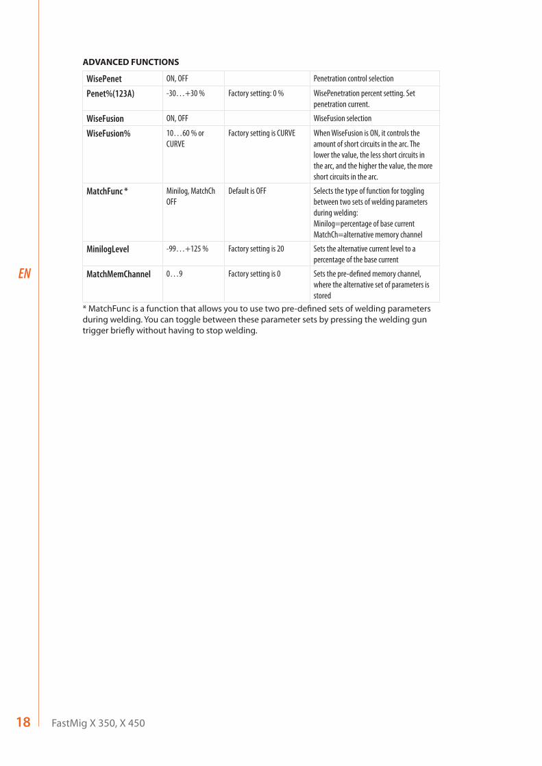
ADVANCED FUNCTIONS
WisePenet ON, OFF Penetration control selection
Penet%(123A) -30…+30 % Factory setting: 0 % WisePenetration percent setting. Set penetration current.
WiseFusion ON, OFF WiseFusion selection
WiseFusion% 10…60 % or CURVE
Factory setting is CURVE When WiseFusion is ON, it controls the amount of short circuits in the arc. The lower the value, the less short circuits in the arc, and the higher the value, the more short circuits in the arc.
MatchFunc * Minilog, MatchCh OFF
Default is OFF Selects the type of function for toggling between two sets of welding parameters during welding: Minilog=percentage of base current MatchCh=alternative memory channel
MinilogLevel -99…+125 % Factory setting is 20 Sets the alternative current level to a percentage of the base current
MatchMemChannel 0…9 Factory setting is 0 Sets the pre-defined memory channel, where the alternative set of parameters is stored
* MatchFunc is a function that allows you to use two pre-defined sets of welding parameters during welding. You can toggle between these parameter sets by pressing the welding gun trigger briefly without having to stop welding.
19© Kemppi Oy / 1520
EN
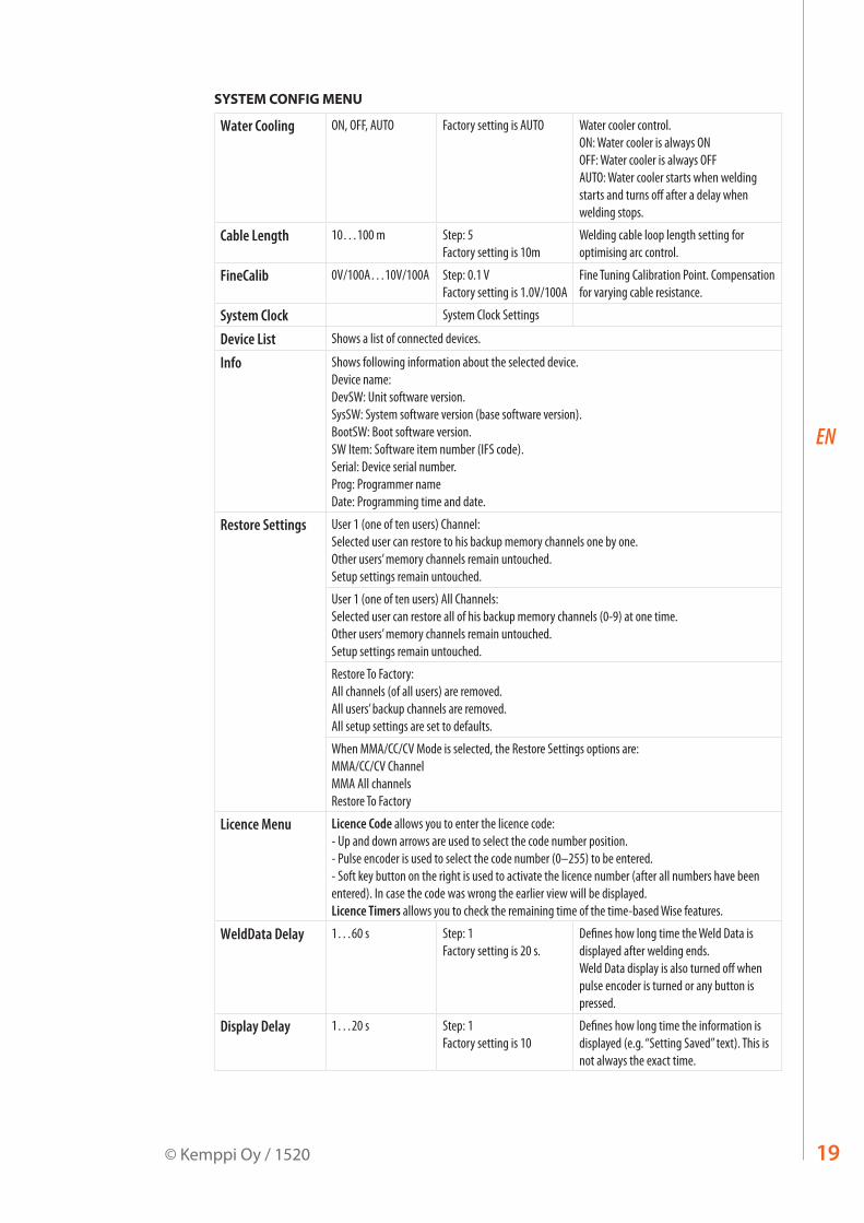
SYSTEM CONFIG MENU
Water Cooling ON, OFF, AUTO Factory setting is AUTO Water cooler control.ON: Water cooler is always ON OFF: Water cooler is always OFF AUTO: Water cooler starts when welding starts and turns off after a delay when welding stops.
Cable Length 10…100 m Step: 5 Factory setting is 10m
Welding cable loop length setting for optimising arc control.
FineCalib 0V/100A…10V/100A Step: 0.1 V Factory setting is 1.0V/100A
Fine Tuning Calibration Point. Compensation for varying cable resistance.
System Clock System Clock Settings
Device List Shows a list of connected devices.
Info Shows following information about the selected device. Device name: DevSW: Unit software version. SysSW: System software version (base software version). BootSW: Boot software version. SW Item: Software item number (IFS code). Serial: Device serial number. Prog: Programmer name Date: Programming time and date.
Restore Settings User 1 (one of ten users) Channel: Selected user can restore to his backup memory channels one by one. Other users’ memory channels remain untouched. Setup settings remain untouched.
User 1 (one of ten users) All Channels: Selected user can restore all of his backup memory channels (0-9) at one time. Other users’ memory channels remain untouched. Setup settings remain untouched.
Restore To Factory: All channels (of all users) are removed. All users’ backup channels are removed. All setup settings are set to defaults.
When MMA/CC/CV Mode is selected, the Restore Settings options are: MMA/CC/CV Channel MMA All channels Restore To Factory
Licence Menu Licence Code allows you to enter the licence code:- Up and down arrows are used to select the code number position. - Pulse encoder is used to select the code number (0–255) to be entered. - Soft key button on the right is used to activate the licence number (after all numbers have been entered). In case the code was wrong the earlier view will be displayed.Licence Timers allows you to check the remaining time of the time-based Wise features.
WeldData Delay 1…60 s Step: 1 Factory setting is 20 s.
Defines how long time the Weld Data is displayed after welding ends. Weld Data display is also turned off when pulse encoder is turned or any button is pressed.
Display Delay 1…20 s Step: 1 Factory setting is 10
Defines how long time the information is displayed (e.g. “Setting Saved” text). This is not always the exact time.
FastMig X 350, X 45020
EN
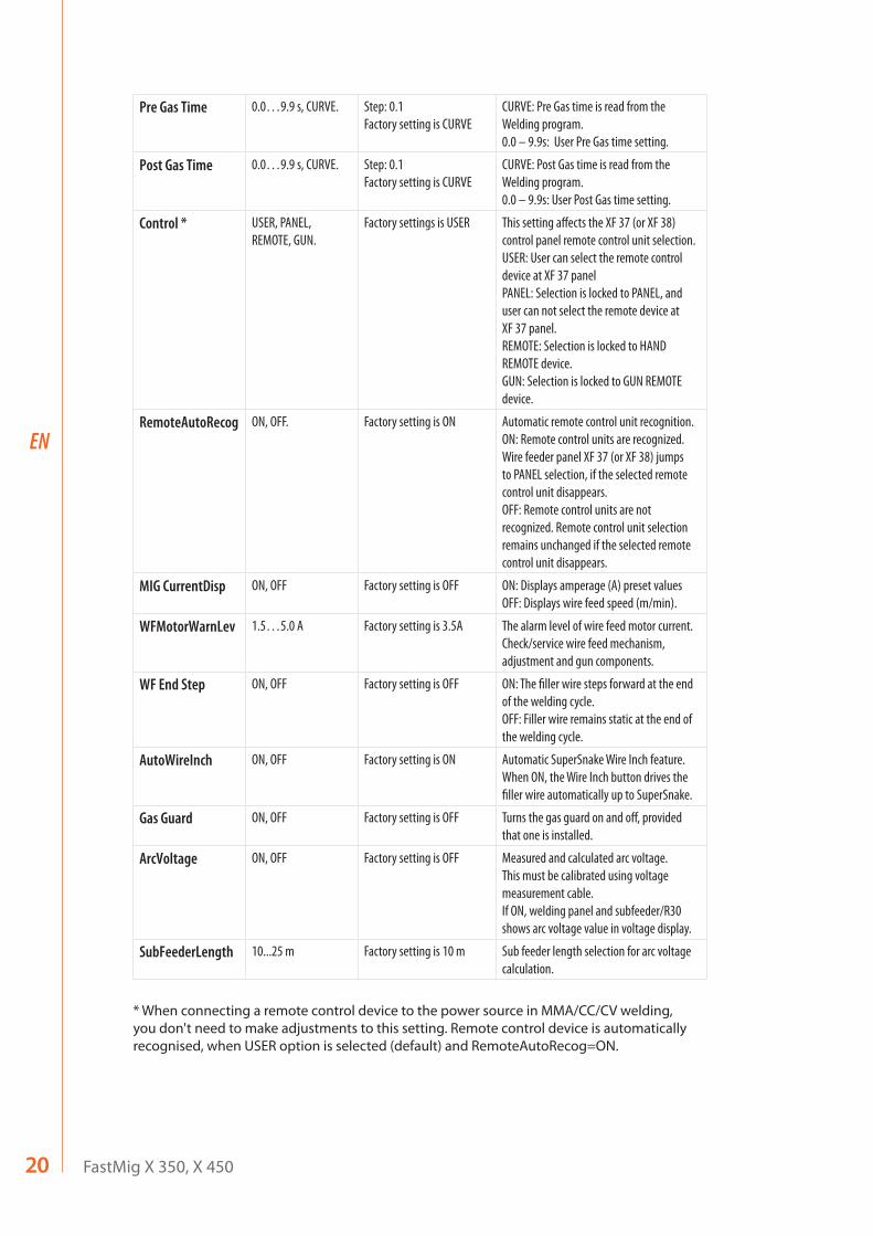
Pre Gas Time 0.0…9.9 s, CURVE. Step: 0.1 Factory setting is CURVE
CURVE: Pre Gas time is read from the Welding program. 0.0 – 9.9s: User Pre Gas time setting.
Post Gas Time 0.0…9.9 s, CURVE. Step: 0.1 Factory setting is CURVE
CURVE: Post Gas time is read from the Welding program. 0.0 – 9.9s: User Post Gas time setting.
Control * USER, PANEL, REMOTE, GUN.
Factory settings is USER This setting affects the XF 37 (or XF 38) control panel remote control unit selection. USER: User can select the remote control device at XF 37 panel PANEL: Selection is locked to PANEL, and user can not select the remote device at XF 37 panel. REMOTE: Selection is locked to HAND REMOTE device. GUN: Selection is locked to GUN REMOTE device.
RemoteAutoRecog ON, OFF. Factory setting is ON Automatic remote control unit recognition. ON: Remote control units are recognized. Wire feeder panel XF 37 (or XF 38) jumps to PANEL selection, if the selected remote control unit disappears. OFF: Remote control units are not recognized. Remote control unit selection remains unchanged if the selected remote control unit disappears.
MIG CurrentDisp ON, OFF Factory setting is OFF ON: Displays amperage (A) preset values OFF: Displays wire feed speed (m/min).
WFMotorWarnLev 1.5…5.0 A Factory setting is 3.5A The alarm level of wire feed motor current.Check/service wire feed mechanism, adjustment and gun components.
WF End Step ON, OFF Factory setting is OFF ON: The filler wire steps forward at the end of the welding cycle. OFF: Filler wire remains static at the end of the welding cycle.
AutoWireInch ON, OFF Factory setting is ON Automatic SuperSnake Wire Inch feature. When ON, the Wire Inch button drives the filler wire automatically up to SuperSnake.
Gas Guard ON, OFF Factory setting is OFF Turns the gas guard on and off, provided that one is installed.
ArcVoltage ON, OFF Factory setting is OFF Measured and calculated arc voltage. This must be calibrated using voltage measurement cable.If ON, welding panel and subfeeder/R30 shows arc voltage value in voltage display.
SubFeederLength 10...25 m Factory setting is 10 m Sub feeder length selection for arc voltage calculation.
* When connecting a remote control device to the power source in MMA/CC/CV welding, you don't need to make adjustments to this setting. Remote control device is automatically recognised, when USER option is selected (default) and RemoteAutoRecog=ON.
21© Kemppi Oy / 1520
EN
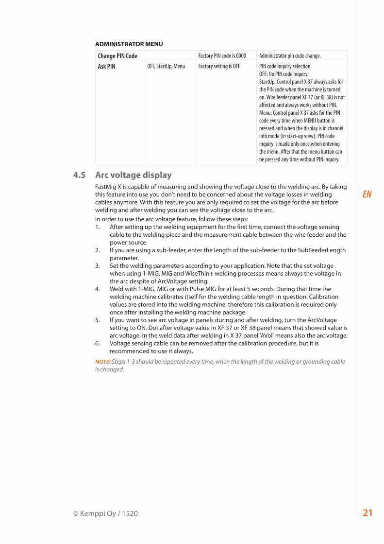
ADMINISTRATOR MENU
Change PIN Code Factory PIN code is 0000 Administrator pin code change.
Ask PIN OFF, StartUp, Menu Factory setting is OFF PIN code inquiry selection OFF: No PIN code inquiry. StartUp: Control panel X 37 always asks for the PIN code when the machine is turned on. Wire feeder panel XF 37 (or XF 38) is not affected and always works without PIN. Menu: Control panel X 37 asks for the PIN code every time when MENU button is pressed and when the display is in channel info mode (in start-up view). PIN code inquiry is made only once when entering the menu. After that the menu button can be pressed any time without PIN inquiry.
4.5 Arc voltage displayFastMig X is capable of measuring and showing the voltage close to the welding arc. By taking this feature into use you don't need to be concerned about the voltage losses in welding cables anymore. With this feature you are only required to set the voltage for the arc before welding and after welding you can see the voltage close to the arc.In order to use the arc voltage feature, follow these steps:1. After setting up the welding equipment for the first time, connect the voltage sensing
cable to the welding piece and the measurement cable between the wire feeder and the power source.
2. If you are using a sub-feeder, enter the length of the sub-feeder to the SubFeederLength parameter.
3. Set the welding parameters according to your application. Note that the set voltage when using 1-MIG, MIG and WiseThin+ welding processes means always the voltage in the arc despite of ArcVoltage setting.
4. Weld with 1-MIG, MIG or with Pulse MIG for at least 5 seconds. During that time the welding machine calibrates itself for the welding cable length in question. Calibration values are stored into the welding machine, therefore this calibration is required only once after installing the welding machine package.
5. If you want to see arc voltage in panels during and after welding, turn the ArcVoltage setting to ON. Dot after voltage value in XF 37 or XF 38 panel means that showed value is arc voltage. In the weld data after welding in X 37 panel 'AVol' means also the arc voltage.
6. Voltage sensing cable can be removed after the calibration procedure, but it is recommended to use it always.
NOTE! Steps 1-3 should be repeated every time, when the length of the welding or grounding cable is changed.
FastMig X 350, X 45022
EN
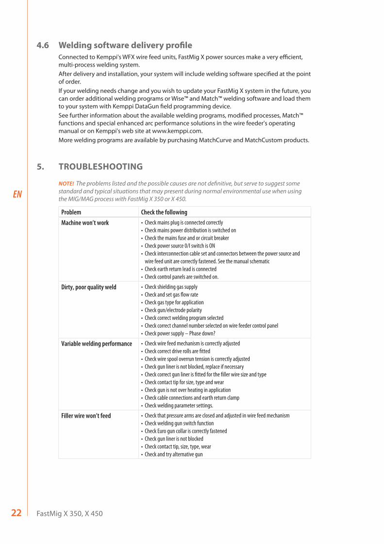
4.6 Welding software delivery profileConnected to Kemppi's WFX wire feed units, FastMig X power sources make a very efficient, multi-process welding system. After delivery and installation, your system will include welding software specified at the point of order. If your welding needs change and you wish to update your FastMig X system in the future, you can order additional welding programs or Wise™ and Match™ welding software and load them to your system with Kemppi DataGun field programming device.See further information about the available welding programs, modified processes, Match™ functions and special enhanced arc performance solutions in the wire feeder's operating manual or on Kemppi's web site at www.kemppi.com.More welding programs are available by purchasing MatchCurve and MatchCustom products.
5. TROUBLESHOOTING
NOTE! The problems listed and the possible causes are not definitive, but serve to suggest some standard and typical situations that may present during normal environmental use when using the MIG/MAG process with FastMig X 350 or X 450.
Problem Check the followingMachine won’t work • Check mains plug is connected correctly
• Check mains power distribution is switched on• Check the mains fuse and or circuit breaker• Check power source 0/I switch is ON• Check interconnection cable set and connectors between the power source and
wire feed unit are correctly fastened. See the manual schematic• Check earth return lead is connected• Check control panels are switched on.
Dirty, poor quality weld • Check shielding gas supply• Check and set gas flow rate• Check gas type for application• Check gun/electrode polarity• Check correct welding program selected• Check correct channel number selected on wire feeder control panel • Check power supply – Phase down?
Variable welding performance • Check wire feed mechanism is correctly adjusted• Check correct drive rolls are fitted• Check wire spool overrun tension is correctly adjusted• Check gun liner is not blocked, replace if necessary• Check correct gun liner is fitted for the filler wire size and type• Check contact tip for size, type and wear• Check gun is not over heating in application • Check cable connections and earth return clamp• Check welding parameter settings.
Filler wire won’t feed • Check that pressure arms are closed and adjusted in wire feed mechanism• Check welding gun switch function• Check Euro gun collar is correctly fastened• Check gun liner is not blocked• Check contact tip, size, type, wear• Check and try alternative gun
23© Kemppi Oy / 1520
EN
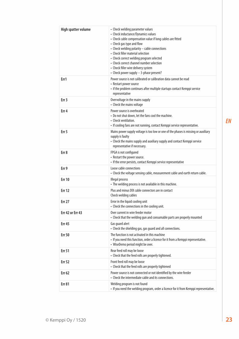
High spatter volume • Check welding parameter values• Check inductance/Dynamics values• Check cable compensation value if long cables are fitted• Check gas type and flow• Check welding polarity – cable connections• Check filler material selection• Check correct welding program selected• Check correct channel number selection • Check filler wire delivery system• Check power supply – 3-phase present?
Err1 Power source is not calibrated or calibration data cannot be read• Restart power source• if the problem continues after multiple startups contact Kemppi service
representative
Err 3 Overvoltage in the mains supply• Check the mains voltage
Err 4 Power source is overheated• Do not shut down, let the fans cool the machine. • Check ventilation. • If cooling fans are not running, contact Kemppi service representative.
Err 5 Mains power supply voltage is too low or one of the phases is missing or auxiliary supply is faulty• Check the mains supply and auxiliary supply and contact Kemppi service
representative if necessary.
Err 8 FPGA is not configured• Restart the power source.• If the error persists, contact Kemppi service representative
Err 9 Loose cable connections• Check the voltage sensing cable, measurement cable and earth return cable.
Err 10 Illegal process• The welding process is not available in this machine.
Err 12 Plus and minus DIX cable connectors are in contactCheck welding cables
Err 27 Error in the liquid cooling unit• Check the connections in the cooling unit.
Err 42 or Err 43 Over current in wire feeder motor• Check that the welding gun and consumable parts are properly mounted
Err 45 Gas guard alert• Check the shielding gas, gas guard and all connections.
Err 50 The function is not activated in this machine• If you need this function, order a licence for it from a Kemppi representative.•WiseDemo period might be over.
Err 51 Rear feed roll may be loose• Check that the feed rolls are properly tightened.
Err 52 Front feed roll may be loose• Check that the feed rolls are properly tightened
Err 62 Power source is not connected or not identified by the wire feeder• Check the intermediate cable and its connections.
Err 81 Welding program is not found• If you need the welding program, order a licence for it from Kemppi representative.
FastMig X 350, X 45024
EN
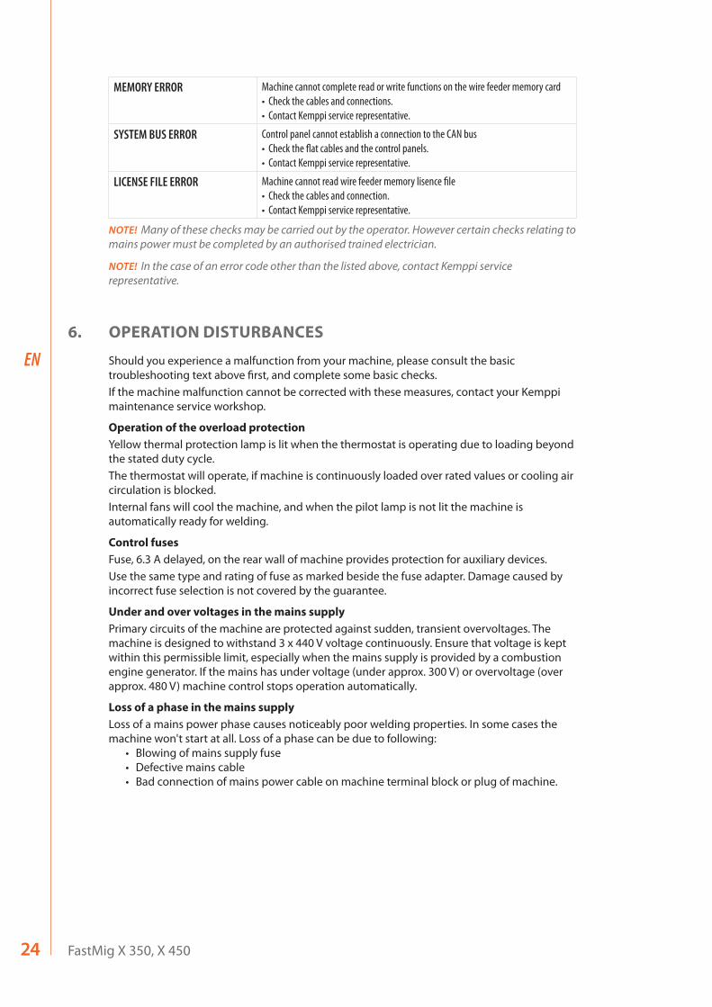
MEMORY ERROR Machine cannot complete read or write functions on the wire feeder memory card• Check the cables and connections.• Contact Kemppi service representative.
SYSTEM BUS ERROR Control panel cannot establish a connection to the CAN bus• Check the flat cables and the control panels.• Contact Kemppi service representative.
LICENSE FILE ERROR Machine cannot read wire feeder memory lisence file• Check the cables and connection.• Contact Kemppi service representative.
NOTE! Many of these checks may be carried out by the operator. However certain checks relating to mains power must be completed by an authorised trained electrician.
NOTE! In the case of an error code other than the listed above, contact Kemppi service representative.
6. OPERATION DISTURBANCES
Should you experience a malfunction from your machine, please consult the basic troubleshooting text above first, and complete some basic checks.If the machine malfunction cannot be corrected with these measures, contact your Kemppi maintenance service workshop.
Operation of the overload protectionYellow thermal protection lamp is lit when the thermostat is operating due to loading beyond the stated duty cycle.The thermostat will operate, if machine is continuously loaded over rated values or cooling air circulation is blocked.Internal fans will cool the machine, and when the pilot lamp is not lit the machine is automatically ready for welding.
Control fusesFuse, 6.3 A delayed, on the rear wall of machine provides protection for auxiliary devices.Use the same type and rating of fuse as marked beside the fuse adapter. Damage caused by incorrect fuse selection is not covered by the guarantee.
Under and over voltages in the mains supplyPrimary circuits of the machine are protected against sudden, transient overvoltages. The machine is designed to withstand 3 x 440 V voltage continuously. Ensure that voltage is kept within this permissible limit, especially when the mains supply is provided by a combustion engine generator. If the mains has under voltage (under approx. 300 V) or overvoltage (over approx. 480 V) machine control stops operation automatically.
Loss of a phase in the mains supplyLoss of a mains power phase causes noticeably poor welding properties. In some cases the machine won't start at all. Loss of a phase can be due to following:
• Blowing of mains supply fuse• Defective mains cable • Bad connection of mains power cable on machine terminal block or plug of machine.
25© Kemppi Oy / 1520
EN
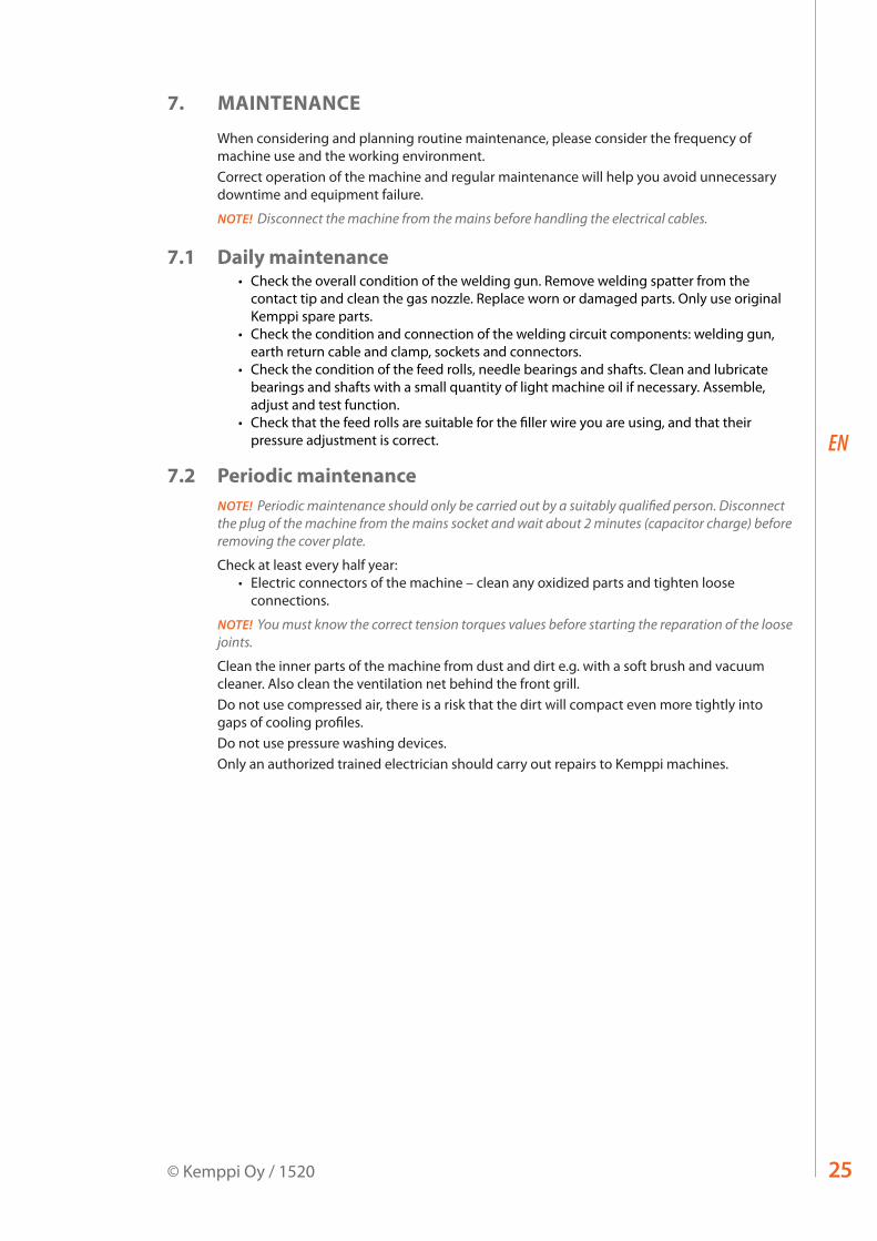
7. MAINTENANCE
When considering and planning routine maintenance, please consider the frequency of machine use and the working environment. Correct operation of the machine and regular maintenance will help you avoid unnecessary downtime and equipment failure.
NOTE! Disconnect the machine from the mains before handling the electrical cables.
7.1 Daily maintenance• Check the overall condition of the welding gun. Remove welding spatter from the
contact tip and clean the gas nozzle. Replace worn or damaged parts. Only use original Kemppi spare parts.
• Check the condition and connection of the welding circuit components: welding gun, earth return cable and clamp, sockets and connectors.
• Check the condition of the feed rolls, needle bearings and shafts. Clean and lubricate bearings and shafts with a small quantity of light machine oil if necessary. Assemble, adjust and test function.
• Check that the feed rolls are suitable for the filler wire you are using, and that their pressure adjustment is correct.
7.2 Periodic maintenanceNOTE! Periodic maintenance should only be carried out by a suitably qualified person. Disconnect the plug of the machine from the mains socket and wait about 2 minutes (capacitor charge) before removing the cover plate.
Check at least every half year:• Electric connectors of the machine – clean any oxidized parts and tighten loose
connections.
NOTE! You must know the correct tension torques values before starting the reparation of the loose joints.
Clean the inner parts of the machine from dust and dirt e.g. with a soft brush and vacuum cleaner. Also clean the ventilation net behind the front grill.Do not use compressed air, there is a risk that the dirt will compact even more tightly into gaps of cooling profiles.Do not use pressure washing devices.Only an authorized trained electrician should carry out repairs to Kemppi machines.
FastMig X 350, X 45026
EN
7.3 Service Workshop maintenanceKemppi Service Workshops complete maintenance according to their Kemppi service agreement.The major points in the maintenance procedure are listed as follows:
• Cleaning of the machine• Checking and maintenance of the welding tools• Checking of connectors, switches and potentiometers• Checking of electric connections• Checking of mains cable and plug• Damaged parts or parts in bad condition are replaced by new ones• Maintenance testing. • Operation and performance values of the machine are checked, and when necessary
adjusted by means of software and test equipment.
Software loadingKemppi Service Workshops can also test and load firmware and welding software.
8. DISPOSAL OF THE MACHINE
Do not dispose of electrical equipment with normal waste!In observance of European Directive 2002/96/EC on waste electrical and electronic equipment, and its implementation in accordance with national law, electrical equipment that has reached the end of its life must be collected separately and taken to an appropriate environmentally responsible recycling facility. The owner of the equipment is obliged to deliver a decommissioned unit to a regional collection centre, as per the instructions of local authorities or a Kemppi representative. By applying this European Directive you will improve the environment and human health.

27© Kemppi Oy / 1520
EN
9. ORDERING CODES
FastMig X 350 power source X 37 control panel included 6103350
FastMig X 350 power source No control panel 610335001
FastMig X 450 power source X 37 control panel included 6103450
FastMig X 450 power source No control panel 610345001
WFX 200 wire feeder 200 mm, regular pulse welding 6103520
WFX 300 wire feeder 300 mm, regular pulse welding 6103530
WFX 200 P Fe wire feeder 200 mm, pipe welding, steel 6103521
WFX 300 P Fe wire feeder 300 mm, pipe welding, steel 6103531
WFX 200 P Ss wire feeder 200 mm, pipe welding, stainless steel 6103522
WFX 300 P Ss wire feeder 300 mm, pipe welding, stainless steel 6103532
WFX 200 AMC wire feeder 200 mm, intelligent pulse welding 6103523
WFX 300 AMC wire feeder 300 mm, intelligent pulse welding 6103533
WFX 200-T wire feeder 200 mm, tailored 6103524
WFX 300 P-T wire feeder 300 mm, tailored 6103535
WFX 300-T wire feeder 300 mm, tailored 6103534
Control devicesRemote X 37 control panel 6103800
ARC Mobile Control adapter * Included with WFX 200 AMC and WFX 300 AMC 6103100
* To use the ARC Mobile Control you need a mobile device with Android 4.0 operating system or newer, Bluetooth feature, and Kemppi’s ARC Mobile Control mobile application. With certain mobile device models, Near Field Communication (NFC) can also be used for smart connection between the welding machine and the mobile device. For more information, please visit www.kemppi.com.
CablesEarth return cable 5 m, 50 mm² 6184511
Earth return cable 5 m, 70 mm² 6184711
MMA welding cable 5 m, 50 mm² 6184501
MMA welding cable 5 m, 70 mm² 6184701
Interconnection cables, air-cooledFASTMIG X 70-1.8-GH 1.8 m 6260468
FASTMIG X 70-5-GH 5 m 6260469
FASTMIG X 70-10-GH 10 m 6260470
FASTMIG X 70-20-GH 20 m 6260471
FASTMIG X 70-30-GH 30 m 6260472
– For other lengths, please contact Kemppi.
FastMig X 350, X 45028
EN
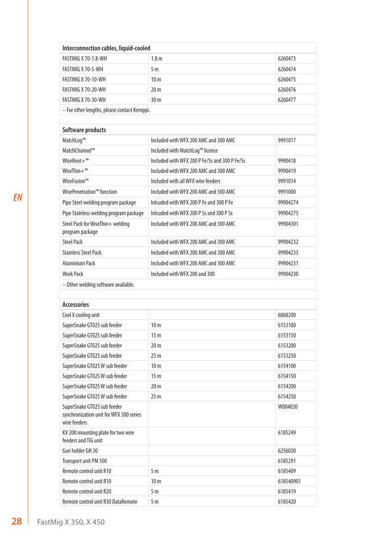
Interconnection cables, liquid-cooledFASTMIG X 70-1.8-WH 1.8 m 6260473
FASTMIG X 70-5-WH 5 m 6260474
FASTMIG X 70-10-WH 10 m 6260475
FASTMIG X 70-20-WH 20 m 6260476
FASTMIG X 70-30-WH 30 m 6260477
– For other lengths, please contact Kemppi.
Software productsMatchLog™ Included with WFX 200 AMC and 300 AMC 9991017
MatchChannel™ Included with MatchLog™ licence
WiseRoot+™ Included with WFX 200 P Fe/Ss and 300 P Fe/Ss 9990418
WiseThin+™ Included with WFX 200 AMC and 300 AMC 9990419
WiseFusion™ Included with all WFX wire feeders 9991014
WisePenetration™ function Included with WFX 200 AMC and 300 AMC 9991000
Pipe Steel welding program package Inlcuded with WFX 200 P Fe and 300 P Fe 99904274
Pipe Stainless welding program package Inlcuded with WFX 200 P Ss and 300 P Ss 99904275
Steel Pack for WiseThin+ welding program package
Included with WFX 200 AMC and 300 AMC 99904301
Steel Pack Included with WFX 200 AMC and 300 AMC 99904232
Stainless Steel Pack Included with WFX 200 AMC and 300 AMC 99904233
Aluminium Pack Included with WFX 200 AMC and 300 AMC 99904231
Work Pack Included with WFX 200 and 300 99904230
– Other welding software available.
AccessoriesCool X cooling unit 6068200
SuperSnake GT02S sub feeder 10 m 6153100
SuperSnake GT02S sub feeder 15 m 6153150
SuperSnake GT02S sub feeder 20 m 6153200
SuperSnake GT02S sub feeder 25 m 6153250
SuperSnake GT02S W sub feeder 10 m 6154100
SuperSnake GT02S W sub feeder 15 m 6154150
SuperSnake GT02S W sub feeder 20 m 6154200
SuperSnake GT02S W sub feeder 25 m 6154250
SuperSnake GT02S sub feeder synchronization unit for WFX 300 series wire feeders
W004030
KV 200 mounting plate for two wire feeders and TIG unit
6185249
Gun holder GH 30 6256030
Transport unit PM 500 6185291
Remote control unit R10 5 m 6185409
Remote control unit R10 10 m 618540901
Remote control unit R20 5 m 6185419
Remote control unit R30 DataRemote 5 m 6185420
29© Kemppi Oy / 1520
EN
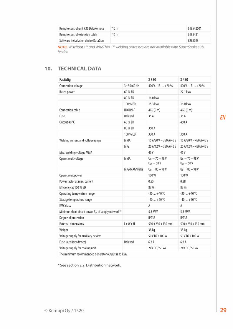
Remote control unit R30 DataRemote 10 m 618542001
Remote control extension cable 10 m 6185481
Software installation device DataGun 6265023
NOTE! WiseRoot+™ and WiseThin+™ welding processes are not available with SuperSnake sub feeder.
10. TECHNICAL DATA
FastMig X 350 X 450Connection voltage 3~50/60 Hz 400 V, -15…+20 % 400 V, -15…+20 %
Rated power 60 % ED 22.1 kVA
80 % ED 16.0 kVA
100 % ED 15.3 kVA 16.0 kVA
Connection cable HO7RN-F 4G6 (5 m) 4G6 (5 m)
Fuse Delayed 35 A 35 A
Output 40 °C 60 % ED 450 A
80 % ED 350 A
100 % ED 330 A 350 A
Welding current and voltage range MMA 15 A/20 V – 350 A/46 V 15 A/20 V – 450 A/46 V
MIG 20 A/12 V – 350 A/46 V 20 A/12 V – 450 A/46 V
Max. welding voltage MMA 46 V 46 V
Open circuit voltage MMA U0 = 70 – 98 V Uav = 50 V
U0 = 70 – 98 V Uav = 50 V
MIG/MAG/Pulse U0 = 80 – 98 V U0 = 80 – 98 V
Open circuit power 100 W 100 W
Power factor at max. current 0.85 0.88
Efficiency at 100 % ED 87 % 87 %
Operating temperature range -20…+40 °C -20…+40 °C
Storage temperature range -40…+60 °C -40…+60 °C
EMC class A A
Minimun short circuit power Ssc of supply network* 5.5 MVA 5.5 MVA
Degree of protection IP23S IP23S
External dimensions L x W x H 590 x 230 x 430 mm 590 x 230 x 430 mm
Weight 38 kg 38 kg
Voltage supply for auxiliary devices 50 V DC / 100 W 50 V DC / 100 W
Fuse (auxiliary device) Delayed 6.3 A 6.3 A
Voltage supply for cooling unit 24V DC / 50 VA 24V DC / 50 VA
The minimum recommended generator output is 35 kVA.
* See section 2.2: Distribution network.

www.kemppi.com
19034501520
KEMPPI OYKempinkatu 1PL 13FIN-15801 LAHTIFINLANDTel +358 3 899 11Telefax +358 3 899 [email protected]
Kotimaan myynti:Tel +358 3 899 11Telefax +358 3 734 [email protected]
KEMPPI SVERIGE ABBox 717S-194 27 UPPLANDS VÄSBYSVERIGETel +46 8 590 783 00Telefax +46 8 590 823 [email protected]
KEMPPI NORGE A/SPostboks 2151, PostterminalenN-3103 TØNSBERGNORGETel +47 33 346000Telefax +47 33 [email protected]
KEMPPI DANMARK A/SLiterbuen 11DK-2740 SKOVLUNDEDANMARKTel +45 4494 1677Telefax +45 4494 [email protected]
KEMPPI BENELUX B.V.NL-4801 EA BREDANEDERLANDTel +31 765717750Telefax +31 [email protected]
KEMPPI (UK) LTDMartti Kemppi BuildingFraser RoadPriory Business ParkBEDFORD, MK44 3WHUNITED KINGDOMTel +44 (0)845 6444201
Telefax +44 (0)845 [email protected]
KEMPPI FRANCE S.A.S.65 Avenue de la Couronne des Prés78681 EPONE CEDEXFRANCETel +33 1 30 90 04 40Telefax +33 1 30 90 04 [email protected]
KEMPPI GMBHPerchstetten 10D-35428 LANGGÖNSDEUTSCHLANDTel +49 6 403 7792 0Telefax +49 6 403 779 79 [email protected]
KEMPPI SPÓŁKA Z O.O.Ul. Borzymowska 3203-565 WARSZAWAPOLANDTel +48 22 7816162Telefax +48 22 [email protected]
KEMPPI AUSTRALIA PTY LTD13 Cullen PlaceP.O. Box 5256, Greystanes NSW 2145SMITHFIELD NSW 2164 AUSTRALIATel. +61 2 9605 9500Telefax +61 2 9605 [email protected]
OOO KEMPPIPolkovaya str. 1, Building 6127018 MOSCOWRUSSIATel +7 495 240 84 03Telefax +7 495 240 84 [email protected]
ООО КЕМППИул. Полковая 1, строение 6127018 МоскваTel +7 495 240 84 03Telefax +7 495 240 84 [email protected]
KEMPPI WELDING TECHNOLOGY (BEIJING) CO., LTD.Unit 105, 1/F, Building #1, No. 26 Xihuan South Rd.,Beijing Economic-Technological Development Area (BDA),100176 BEIJINGCHINATel +86-10-6787 6064+86-10-6787 1282Telefax +86-10-6787 [email protected]
肯倍焊接技术(北京) 有限公司中国北京经济技术开发区 西环南路26号1号楼1层105室(100176)电话:+86-10-6787 6064/1282传真:+86-10-6787 [email protected]
KEMPPI INDIA PVT LTDLAKSHMI TOWERSNew No. 2/770, First Main Road, Kazura Garden, Neelankarai, CHENNAI - 600 041 TAMIL NADUTel +91-44-4567 1200Telefax +91-44-4567 [email protected]
KEMPPI WELDING SOLUTIONS SDN BHDNo 12A, Jalan TP5A,Taman Perindustrian UEP,47600 Subang Jaya, SELANGOR, MALAYSIATel +60 3 80207035Telefax +60 3 [email protected]