Embed Size (px)
Citation preview

ウォームギア式 バルブ アクチュエータWorm gear valve actuators
BULLETIN L-024E 0912AT(TA)
横 浜 支 店
大 阪 支 店
札幌営業所
仙台営業所
名古屋営業所
広島営業所
福岡営業所
福島サービス センター
藤沢事業所
柏崎事業所
(事業所)
(事業所)
(事業所)
(事業所)
(事業所)
(事業所)
〒220-0004 横浜市西区北幸1-11-11(NOF横浜西口ビル9階) TEL.045-326-2061 FAX.045-320-5961
〒564-0053 大阪府吹田市江の木町26-30 TEL.06-6368-3200 FAX.06-6368-3201
〒003-0873 札幌市白石区米里3条2-8-1 TEL.011-871-3385 FAX.011-871-3387
〒980-0014 仙台市青葉区本町1-12-12(GMビル9階) TEL.022-221-1818 FAX.022-224-4656
〒459-8001 名古屋市緑区大高町一番割6-1 TEL.052-625-7780 FAX.052-625-7785
〒733-0003 広島市西区三篠町3-16-4 TEL.082-237-7377 FAX.082-237-7370
〒810-0802 福岡市博多区中州中島町2-3(福岡フジランドビル4階) TEL.092-263-8355 FAX.092-263-3350
〒979-0603 福島県双葉郡楢葉町井出字浄光西24 TEL.0240-25-4865 FAX.0240-25-4361
〒252-0815 神奈川県藤沢市石川1831 TEL.0466-45-2290 FAX.0466-43-6364
〒945-0106 新潟県柏崎市大字土合907TEL.0257-23-7669 FAX.0257-22-9024
千葉事業所
京浜事業所
金沢事業所
若狭事業所
浜岡出張所
〒289-1107 千葉県八街市八街は16-141 TEL.043-444-3810 FAX.043-444-3812
〒230-0025 横浜市鶴見区市場大和町1-14(サンライズハイツ2 1階) TEL.045-504-7577 FAX.045-504-7558
〒921-8064 石川県金沢市八日市1-667 TEL.076-226-6850 FAX.076-226-6851
〒625-0014 京都府舞鶴市鹿原196-1 TEL.0773-66-0571 FAX.0773-66-0129
〒437-1695 静岡県御前崎市佐倉5561 中部電力(株)浜岡原子力発電所内 保修3棟 TEL.0537-86-9704 FAX.0537-86-9720
本 社 〒252-0811 神奈川県藤沢市桐原町7番地 TEL.0466-45-2111 FAX.0466-45-3370
Sales Head QuarterNOF Yokohama Nishiguchi Building1-11-11 Kitasaiwai, Nishiku,Yokohama 220-0004 JapanTelephone:045-326-2065Facsimile:045-320-5961Sales Offices:Yokohama, Osaka, Sapporo, Sendai, Nagoya, Hiroshima, FukuokaHead Office:7 Kirihara-cho, Fujisawa-shi Kanagawa-ken. 252-0811 Japan
2 3
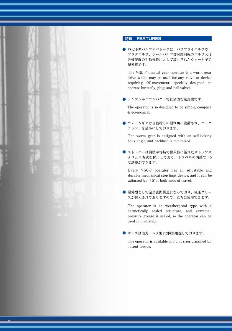
The VGC-F manual gear operator is a worm gear drive which may be used for any valve or device requiring 90°movement, specially designed to operate butterfly, plug, and ball valves.
The worm gear is designed with an self-locking helix angle, and backlash is minimized.
The operator is so designed to be simple, compact & economical.
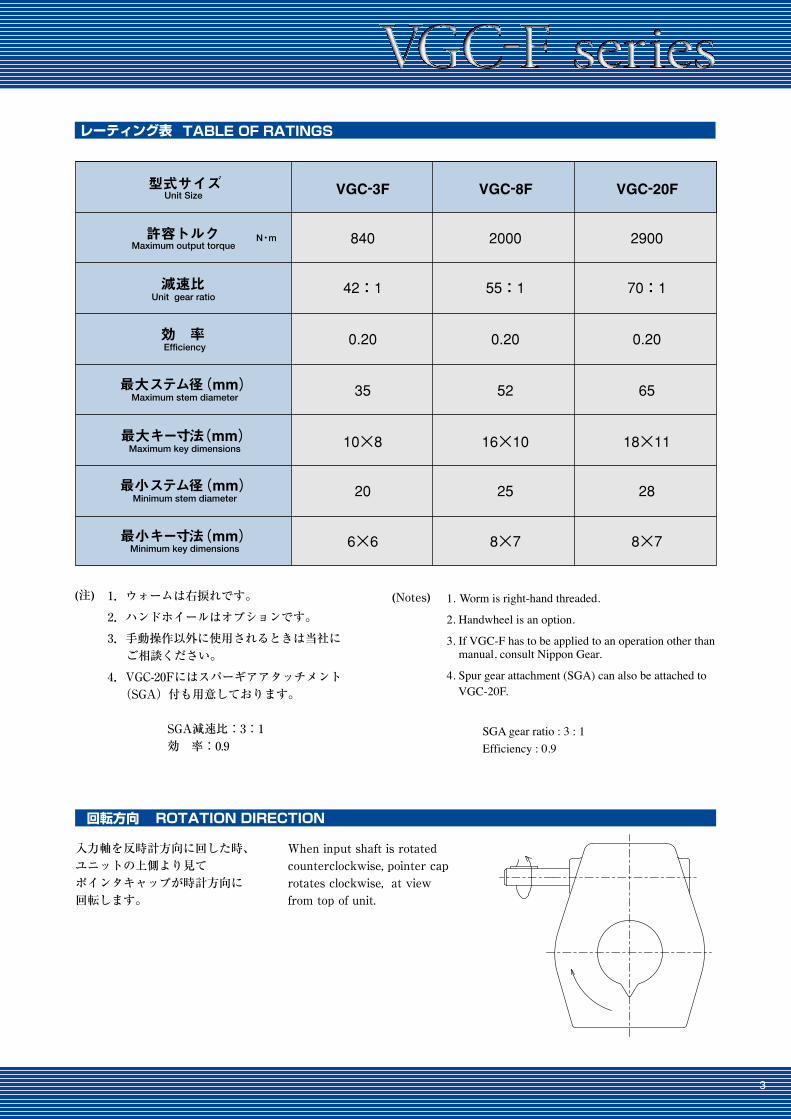
When input shaft is rotated counterclockwise, pointer cap rotates clockwise, at view from top of unit.
1. Worm is right-hand threaded.
2. Handwheel is an option.
3. If VGC-F has to be applied to an operation other than manual, consult Nippon Gear.
4. Spur gear attachment (SGA) can also be attached to VGC-20F.
SGA gear ratio : 3 : 1 Efficiency : 0.9
FEATURES特長
ROTATION DIRECTION 回転方向
レーティング表
●
●
●
●
●
●
TABLE OF RATINGS
型式サイズ VGC-3F
840
42:1 55:1 70:1
0.20 0.20 0.20
35 52 65
20 25 28
10×8 16×10 18×11
6×6 8×7 8×7
2000 2900
VGC-8F VGC-20FUnit Size
許容トルクMaximum output torque
N・m
Unit gear ratio減速比
Efficiency効 率
Maximum stem diameter 最大ステム径(mm)
Maximum key dimensions 最大キー寸法(mm)
Minimum key dimensions 最小キー寸法(mm)
Minimum stem diameter 最小ステム径(mm)
VGC-F型バルブオペレータは、バタフライバルブや、プラグバルブ、ボールバルブ等90度回転のバルブ又は各種装置の手動操作用として設計されたウォームギア減速機です。
シンプルかつコンパクトで経済的な減速機です。
The operator is available in 3 unit sizes classified by output torque.
The operator is an weatherproof type with a hermetically sealed structure, and extreme-pressure grease is sealed, so the operator can be used immediately.
Every VGC-F operator has an adjustable and durable mechanical stop limit device, and it can be adjusted by ±5°at both ends of travel.
サイズは出力トルク別に3種類用意しております。
屋外型として完全密閉構造になっており、極圧グリースが封入されておりますので、直ちに使用できます。
ストッパーは調整が容易で耐久性に優れたストップスクリュウ方式を採用しており、トラベルの両端で±5度調整ができます。
ウォームギアは自動締りの捩れ角に設計され、バックラッシュを最小にしております。
1.ウォームは右捩れです。
2.ハンドホイールはオプションです。
3.手動操作以外に使用されるときは当社に ご相談ください。
4.VGC-20Fにはスパーギアアタッチメント (SGA)付も用意しております。
SGA減速比:3:1 効 率:0.9
入力軸を反時計方向に回した時、ユニットの上側より見てポインタキャップが時計方向に回転します。
(注) (Notes)
2 3
The VGC-F manual gear operator is a worm gear drive which may be used for any valve or device requiring 90°movement, specially designed to operate butterfly, plug, and ball valves.
The worm gear is designed with an self-locking helix angle, and backlash is minimized.
The operator is so designed to be simple, compact & economical.
When input shaft is rotated counterclockwise, pointer cap rotates clockwise, at view from top of unit.
1. Worm is right-hand threaded.
2. Handwheel is an option.
3. If VGC-F has to be applied to an operation other than manual, consult Nippon Gear.
4. Spur gear attachment (SGA) can also be attached to VGC-20F.
SGA gear ratio : 3 : 1 Efficiency : 0.9
FEATURES特長
ROTATION DIRECTION 回転方向
レーティング表
●
●
●
●
●
●
TABLE OF RATINGS
型式サイズ VGC-3F
840
42:1 55:1 70:1
0.20 0.20 0.20
35 52 65
20 25 28
10×8 16×10 18×11
6×6 8×7 8×7
2000 2900
VGC-8F VGC-20FUnit Size
許容トルクMaximum output torque
N・m
Unit gear ratio減速比
Efficiency効 率
Maximum stem diameter 最大ステム径(mm)
Maximum key dimensions 最大キー寸法(mm)
Minimum key dimensions 最小キー寸法(mm)
Minimum stem diameter 最小ステム径(mm)
VGC-F型バルブオペレータは、バタフライバルブや、プラグバルブ、ボールバルブ等90度回転のバルブ又は各種装置の手動操作用として設計されたウォームギア減速機です。
シンプルかつコンパクトで経済的な減速機です。
The operator is available in 3 unit sizes classified by output torque.
The operator is an weatherproof type with a hermetically sealed structure, and extreme-pressure grease is sealed, so the operator can be used immediately.
Every VGC-F operator has an adjustable and durable mechanical stop limit device, and it can be adjusted by ±5°at both ends of travel.
サイズは出力トルク別に3種類用意しております。
屋外型として完全密閉構造になっており、極圧グリースが封入されておりますので、直ちに使用できます。
ストッパーは調整が容易で耐久性に優れたストップスクリュウ方式を採用しており、トラベルの両端で±5度調整ができます。
ウォームギアは自動締りの捩れ角に設計され、バックラッシュを最小にしております。
1.ウォームは右捩れです。
2.ハンドホイールはオプションです。
3.手動操作以外に使用されるときは当社に ご相談ください。
4.VGC-20Fにはスパーギアアタッチメント (SGA)付も用意しております。
SGA減速比:3:1 効 率:0.9
入力軸を反時計方向に回した時、ユニットの上側より見てポインタキャップが時計方向に回転します。
(注) (Notes)
4 5
寸法図 DIMENSIONS 構造図 PARTS LIST
VGC-20F
8"
12"
HL 質量⦆
4kg
62
92 308
203
ハンドホイール寸法
HD HB
44
60
18" 10 kg97 460 60
24" 14 kg94 610 60
1.4 kg VGC-3F
VGC-8F ~20F
VGC-8F ~20F
VGC-20F
Weight Unit Size適合型式⦆
Handwheel dimensions
1ハウジング Housing
1ハウジングカバー Housing Cover
1ポインターキャップ Pointer Cap
ウォームギア Worm Gear 1
2
1
1
1
1
1
1
ステムナット Stem Nut
2
3
4
5
6
7
8
10
11
12 1
9 2ベアリング Bearing
“O”リング “O”Ring
ウォーム Worm
ウォームシャフト Worm Shaft
ストップスクリュウ Stop Screw
キー Key
13 2
14 4
15
16
1
エンドキャップ End Cap
スペーサ Spacer
“O”リング “O”Ring
スルーキャップ Thru Cap
オプション Optionハンドホイール Handwheel 1
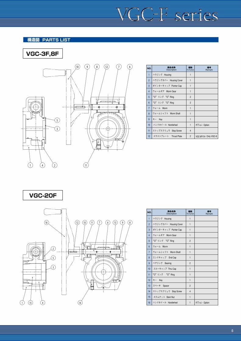
NO. 部品名称Description
個数 備考The Number Remark
1ハウジング Housing
1ハウジングカバー Housing Cover
1ポインターキャップ Pointer Cap
ウォームギア Worm Gear 1
2
2
1
1
1
1
4
スラストプレート Thrust Plate
2
3
4
5
6
7
8
10
11
12 2
9 1
“O” リング “O”Ring
“O” リング “O”Ring
ウォーム Worm
ウォームシャフト Worm Shaft
ストップスクリュウ Stop Screw
キー Key
ハンドホイール Handwheel オプション
VGC-8F のみ
Option
Only VGC-8
NO. 部品名称Description
個数 備考The Number Remark
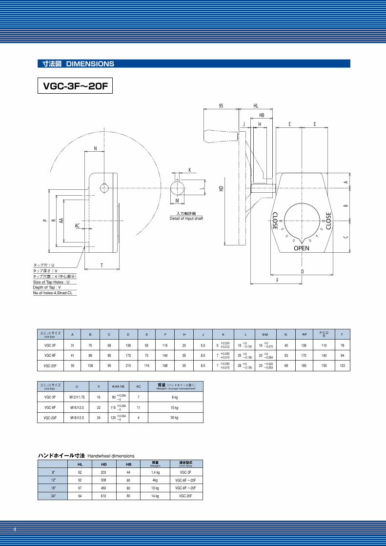
VGC-3F~20F
VGC-3F
ユニットサイズUnit Size
VGC-8F
VGC-20F
A
31
41
50
B
70
89
108
C
69
85
95
D
138
170
210
E
55
70
116
F
115
140
188
H
25
35
35
J K
5.5
8.5
8.5
5+0.024+0.012
+0.030+0.015
+0.030+0.015
7
7
N
40
53
68
ΦP T
138
170
185
P.C.DR
110
140
150
78
94
123
L
18 +0-0.130
+0-0.136
+0-0.136
25
28
ΦM
16+0-0.070
+0-0.084
-0.020-0.053
22
25
VGC-3F
ユニットサイズUnit Size
VGC-8F
VGC-20F
質量⦆ (ハンドホイール除く)⦆
15 kg
30 kg
V
16
22
24
ΦAA H8
90 +0.054-0
+0.054-0
+0.054-0
115
120
U
M12×1.75
M16×2.0
M18×2.5
8 kg
Weight(except handwheel)AC
7
11
4
OPEN
CLO
SE CLO
SE
HD
AB
C
HL
HB
HJ
95
E
F
D
E
M
K
L
Detail of input shaft入力軸詳細
P R AA
AC
T
N
No.of holes:4,Strad.CL
タップ深さ:Vタップ穴数:4(中心振分)Size of Tap Holes : U
タップ穴:U
Depth of Tap : V
VGC-3F,8F
67128910
11
5
3
241
16 12 10 11 7 6 13 9 8
141 15 4
2
5
3
4 5
寸法図 DIMENSIONS 構造図 PARTS LIST
VGC-20F
8"
12"
HL 質量⦆
4kg
62
92 308
203
ハンドホイール寸法
HD HB
44
60
18" 10 kg97 460 60
24" 14 kg94 610 60
1.4 kg VGC-3F
VGC-8F ~20F
VGC-8F ~20F
VGC-20F
Weight Unit Size適合型式⦆
Handwheel dimensions
1ハウジング Housing
1ハウジングカバー Housing Cover
1ポインターキャップ Pointer Cap
ウォームギア Worm Gear 1
2
1
1
1
1
1
1
ステムナット Stem Nut
2
3
4
5
6
7
8
10
11
12 1
9 2ベアリング Bearing
“O”リング “O”Ring
ウォーム Worm
ウォームシャフト Worm Shaft
ストップスクリュウ Stop Screw
キー Key
13 2
14 4
15
16
1
エンドキャップ End Cap
スペーサ Spacer
“O”リング “O”Ring
スルーキャップ Thru Cap
オプション Optionハンドホイール Handwheel 1
NO. 部品名称Description
個数 備考The Number Remark
1ハウジング Housing
1ハウジングカバー Housing Cover
1ポインターキャップ Pointer Cap
ウォームギア Worm Gear 1
2
2
1
1
1
1
4
スラストプレート Thrust Plate
2
3
4
5
6
7
8
10
11
12 2
9 1
“O” リング “O”Ring
“O” リング “O”Ring
ウォーム Worm
ウォームシャフト Worm Shaft
ストップスクリュウ Stop Screw
キー Key
ハンドホイール Handwheel オプション
VGC-8F のみ
Option
Only VGC-8
NO. 部品名称Description
個数 備考The Number Remark
VGC-3F~20F
VGC-3F
ユニットサイズUnit Size
VGC-8F
VGC-20F
A
31
41
50
B
70
89
108
C
69
85
95
D
138
170
210
E
55
70
116
F
115
140
188
H
25
35
35
J K
5.5
8.5
8.5
5+0.024+0.012
+0.030+0.015
+0.030+0.015
7
7
N
40
53
68
ΦP T
138
170
185
P.C.DR
110
140
150
78
94
123
L
18 +0-0.130
+0-0.136
+0-0.136
25
28
ΦM
16+0-0.070
+0-0.084
-0.020-0.053
22
25
VGC-3F
ユニットサイズUnit Size
VGC-8F
VGC-20F
質量⦆ (ハンドホイール除く)⦆
15 kg
30 kg
V
16
22
24
ΦAA H8
90 +0.054-0
+0.054-0
+0.054-0
115
120
U
M12×1.75
M16×2.0
M18×2.5
8 kg
Weight(except handwheel)AC
7
11
4
OPEN
CLO
SE CLO
SE
HD
AB
C
HL
HB
HJ
95
E
F
D
E
M
K
L
Detail of input shaft入力軸詳細
P R AA
AC
T
N
No.of holes:4,Strad.CL
タップ深さ:Vタップ穴数:4(中心振分)Size of Tap Holes : U
タップ穴:U
Depth of Tap : V
VGC-3F,8F
67128910
11
5
3
241
16 12 10 11 7 6 13 9 8
141 15 4
2
5
3
6 7
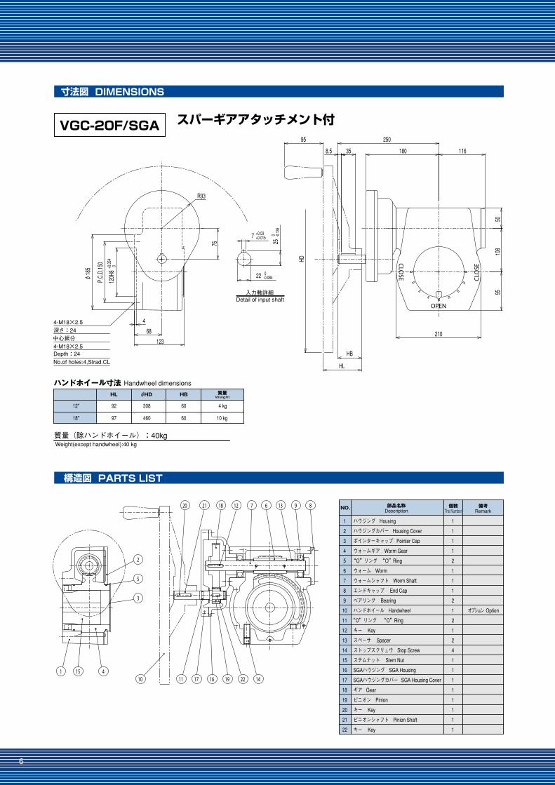
寸法図 DIMENSIONS
構造図 PARTS LIST
バルブ取付要領 MOUNTING INSTRUCTIONS
ストッパーの調整 STOPPER ADJUSTMENT
ハンドホイールの回転方向 DIRECTION OF HANDWHEEL ROTATION
スパーギアアタッチメント付
12"
18"
HL 質量⦆
10 kg
92
97 460
308
ハンドホイール寸法HD HB
60
60
4 kg
質量(除ハンドホイール):40kg
φWeight
Handwheel dimensions
Weight(except handwheel):40 kg
1ハウジング Housing
1ハウジングカバー Housing Cover
1ポインターキャップ Pointer Cap
ウォームギア Worm Gear 1
2
1
1
1
1
1
2
SGAハウジング SGA Housing
2
3
4
5
6
7
8
10
11
12 1
9 2ベアリング Bearing
“O”リング “O”Ring
ウォーム Worm
ウォームシャフト Worm Shaft
ストップスクリュウ Stop Screw
キー Key
13 2
14 4
15 1
16 1
エンドキャップ End Cap
スペーサ Spacer
ステムナット Stem Nut
“O”リング “O”Ring
ハンドホイール Handwheel オプション Option
SGAハウジングカバー SGA Housing Cover17 1
ギア Gear18 1
ピニオン Pinion19 1
キー Key20 1
ピニオンシャフト Pinion Shaft21 1
キー Key22 1
NO. 部品名称Description
個数 備考The Number Remark
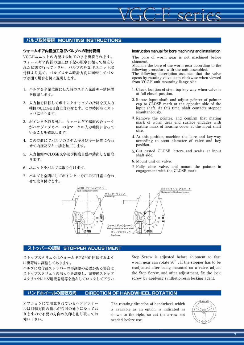
VGC-Fユニットの内径は未加工のまま出荷されます。ウォームギア内径の加工は下記の順序に従って組立られた状態で行って下さい。バルブのVGC-Fユニット取付側より見て、バルブステム時計方向に回転してバルブが開く場合を例に説明します。
ストップスクリュウはウォームギアが90°回転するように出荷時に調整してあります。バルブに取付後ストッパーの再調整の必要がある場合はストップスクリュウの出入りを調整し、調整後ストップスクリュウにネジ用接着剤等を塗布してロックして下さい
オプションにて用意されているハンドホイールは回転方向の指示が右図の通りになっておりますので不要の方向の矢印を削り取ってお使い下さい。
バルブを全閉位置にした時のステム先端キー溝位置を確認します。
入力軸を回転してポインタキャップの指針を反入力軸側のCLOSE目盛に合わせます。この時同時にストッパに当ります。
ポインタを取り外し、ウォームギア端面の合マークがハウジングカバーの合マークの入力軸側に合っていることを確認します。
この位置にてバルブのステム径及びキー位置に合わせて内径及びキー溝を加工します。
入力軸側のCLOSE文字及び開度目盛の鋳出しを削取ります。
ユニットをバルブに取り付けます。
バルブを全閉にしてポインターをCLOSE目盛に合わせて取り付けます。
ウォームギア内径加工及びバルブへの取付要領
1.
2.
3.
4.
5.
6.
7.
The bore of worm gear is not machined before shipment.Machine the bore of the worm gear according to the following procedure with the unit assembled.The following description assumes that the valve opens by rotating valve stem clockwise when viewed from VGC-F unit mounting flange side.
The rotating direction of handwheel, which is available as an option, is indicated as shown to the right, so cut the arrow not needed before use.
Check location of stem top key-way when valve is at full closed position.
Rotate input shaft, and adjust pointer of pointer cap to CLOSE mark at the opposite side of the input shaft. At this time, shaft contacts stopper simultaneously.
Remove the pointer, and confirm that mating mark of worm gear end surface engages with mating mark of housing cover at the input shaft side.
At this position, machine the bore and key-way according to stem diameter of valve and key position.
Cut casted CLOSE letters and scales at input shaft side.
Mount unit on valve.Fully close valve, and mount the pointer in engagement with the CLOSE mark.
Stop Screw is adjusted before shipment so that worm gear can rotate 90°. If the stopper has to be readjusted after being mounted on a valve, adjust the Stop Screw, and after adjustment, fix the lock screw by applying synthetic-resin locking agent.
Instruction manual for bore machining and installation
1.
2.
3.
4.
5.
6.
7.
VGC-20F/SGA
Detail of input shaft入力軸詳細
7 +0.03+0.015
25 0 -0.136
22 0-0.084
深さ:24中心振分4-M18×2.5
4-M18×2.5
Depth:24No.of holes:4,Strad.CL
185
P.C.D.150
120H8+0.054
0
φ
4
123
68
76
R93
116180
95
8.5 35
250
210
50108
95
HD
HB
HL
OPEN
CLO
SE CLO
SE
1 15 4
2
5
3
7 6 13 9 812182120
10 1711 16 19 22 14
Mating mark of the housing cover
Mating mark of the worm wheel
Stop Screw
ハウジングカバーの合マーク
ウォームギアの合マーク
ストップスクリュウ
Input shaft (Worm Shaft)
Pointer capポインターキャップ
入力軸(ウォームシャフト)
6 7
寸法図 DIMENSIONS
構造図 PARTS LIST
バルブ取付要領 MOUNTING INSTRUCTIONS
ストッパーの調整 STOPPER ADJUSTMENT
ハンドホイールの回転方向 DIRECTION OF HANDWHEEL ROTATION
スパーギアアタッチメント付
12"
18"
HL 質量⦆
10 kg
92
97 460
308
ハンドホイール寸法HD HB
60
60
4 kg
質量(除ハンドホイール):40kg
φWeight
Handwheel dimensions
Weight(except handwheel):40 kg
1ハウジング Housing
1ハウジングカバー Housing Cover
1ポインターキャップ Pointer Cap
ウォームギア Worm Gear 1
2
1
1
1
1
1
2
SGAハウジング SGA Housing
2
3
4
5
6
7
8
10
11
12 1
9 2ベアリング Bearing
“O”リング “O”Ring
ウォーム Worm
ウォームシャフト Worm Shaft
ストップスクリュウ Stop Screw
キー Key
13 2
14 4
15 1
16 1
エンドキャップ End Cap
スペーサ Spacer
ステムナット Stem Nut
“O”リング “O”Ring
ハンドホイール Handwheel オプション Option
SGAハウジングカバー SGA Housing Cover17 1
ギア Gear18 1
ピニオン Pinion19 1
キー Key20 1
ピニオンシャフト Pinion Shaft21 1
キー Key22 1
NO. 部品名称Description
個数 備考The Number Remark
VGC-Fユニットの内径は未加工のまま出荷されます。ウォームギア内径の加工は下記の順序に従って組立られた状態で行って下さい。バルブのVGC-Fユニット取付側より見て、バルブステム時計方向に回転してバルブが開く場合を例に説明します。
ストップスクリュウはウォームギアが90°回転するように出荷時に調整してあります。バルブに取付後ストッパーの再調整の必要がある場合はストップスクリュウの出入りを調整し、調整後ストップスクリュウにネジ用接着剤等を塗布してロックして下さい
オプションにて用意されているハンドホイールは回転方向の指示が右図の通りになっておりますので不要の方向の矢印を削り取ってお使い下さい。
バルブを全閉位置にした時のステム先端キー溝位置を確認します。
入力軸を回転してポインタキャップの指針を反入力軸側のCLOSE目盛に合わせます。この時同時にストッパに当ります。
ポインタを取り外し、ウォームギア端面の合マークがハウジングカバーの合マークの入力軸側に合っていることを確認します。
この位置にてバルブのステム径及びキー位置に合わせて内径及びキー溝を加工します。
入力軸側のCLOSE文字及び開度目盛の鋳出しを削取ります。
ユニットをバルブに取り付けます。
バルブを全閉にしてポインターをCLOSE目盛に合わせて取り付けます。
ウォームギア内径加工及びバルブへの取付要領
1.
2.
3.
4.
5.
6.
7.
The bore of worm gear is not machined before shipment.Machine the bore of the worm gear according to the following procedure with the unit assembled.The following description assumes that the valve opens by rotating valve stem clockwise when viewed from VGC-F unit mounting flange side.
The rotating direction of handwheel, which is available as an option, is indicated as shown to the right, so cut the arrow not needed before use.
Check location of stem top key-way when valve is at full closed position.
Rotate input shaft, and adjust pointer of pointer cap to CLOSE mark at the opposite side of the input shaft. At this time, shaft contacts stopper simultaneously.
Remove the pointer, and confirm that mating mark of worm gear end surface engages with mating mark of housing cover at the input shaft side.
At this position, machine the bore and key-way according to stem diameter of valve and key position.
Cut casted CLOSE letters and scales at input shaft side.
Mount unit on valve.Fully close valve, and mount the pointer in engagement with the CLOSE mark.
Stop Screw is adjusted before shipment so that worm gear can rotate 90°. If the stopper has to be readjusted after being mounted on a valve, adjust the Stop Screw, and after adjustment, fix the lock screw by applying synthetic-resin locking agent.
Instruction manual for bore machining and installation
1.
2.
3.
4.
5.
6.
7.
VGC-20F/SGA
Detail of input shaft入力軸詳細
7 +0.03+0.015
25 0 -0.136
22 0-0.084
深さ:24中心振分4-M18×2.5
4-M18×2.5
Depth:24No.of holes:4,Strad.CL
185
P.C.D.150
120H8+0.054
0
φ
4
123
68
76
R93
116180
95
8.5 35
250
210
50108
95
HD
HB
HL
OPEN
CLO
SE CLO
SE
1 15 4
2
5
3
7 6 13 9 812182120
10 1711 16 19 22 14
Mating mark of the housing cover
Mating mark of the worm wheel
Stop Screw
ハウジングカバーの合マーク
ウォームギアの合マーク
ストップスクリュウ
Input shaft (Worm Shaft)
Pointer capポインターキャップ
入力軸(ウォームシャフト)
ウォームギア式 バルブ アクチュエータWorm gear valve actuators
BULLETIN L-024E 0912AT(TA)
横 浜 支 店
大 阪 支 店
札幌営業所
仙台営業所
名古屋営業所
広島営業所
福岡営業所
福島サービス センター
藤沢事業所
柏崎事業所
(事業所)
(事業所)
(事業所)
(事業所)
(事業所)
(事業所)
〒220-0004 横浜市西区北幸1-11-11(NOF横浜西口ビル9階) TEL.045-326-2061 FAX.045-320-5961
〒564-0053 大阪府吹田市江の木町26-30 TEL.06-6368-3200 FAX.06-6368-3201
〒003-0873 札幌市白石区米里3条2-8-1 TEL.011-871-3385 FAX.011-871-3387
〒980-0014 仙台市青葉区本町1-12-12(GMビル9階) TEL.022-221-1818 FAX.022-224-4656
〒459-8001 名古屋市緑区大高町一番割6-1 TEL.052-625-7780 FAX.052-625-7785
〒733-0003 広島市西区三篠町3-16-4 TEL.082-237-7377 FAX.082-237-7370
〒810-0802 福岡市博多区中州中島町2-3(福岡フジランドビル4階) TEL.092-263-8355 FAX.092-263-3350
〒979-0603 福島県双葉郡楢葉町井出字浄光西24 TEL.0240-25-4865 FAX.0240-25-4361
〒252-0815 神奈川県藤沢市石川1831 TEL.0466-45-2290 FAX.0466-43-6364
〒945-0106 新潟県柏崎市大字土合907TEL.0257-23-7669 FAX.0257-22-9024
千葉事業所
京浜事業所
金沢事業所
若狭事業所
浜岡出張所
〒289-1107 千葉県八街市八街は16-141 TEL.043-444-3810 FAX.043-444-3812
〒230-0025 横浜市鶴見区市場大和町1-14(サンライズハイツ2 1階) TEL.045-504-7577 FAX.045-504-7558
〒921-8064 石川県金沢市八日市1-667 TEL.076-226-6850 FAX.076-226-6851
〒625-0014 京都府舞鶴市鹿原196-1 TEL.0773-66-0571 FAX.0773-66-0129
〒437-1695 静岡県御前崎市佐倉5561 中部電力(株)浜岡原子力発電所内 保修3棟 TEL.0537-86-9704 FAX.0537-86-9720
本 社 〒252-0811 神奈川県藤沢市桐原町7番地 TEL.0466-45-2111 FAX.0466-45-3370
Sales Head QuarterNOF Yokohama Nishiguchi Building1-11-11 Kitasaiwai, Nishiku,Yokohama 220-0004 JapanTelephone:045-326-2065Facsimile:045-320-5961Sales Offices:Yokohama, Osaka, Sapporo, Sendai, Nagoya, Hiroshima, FukuokaHead Office:7 Kirihara-cho, Fujisawa-shi Kanagawa-ken. 252-0811 Japan