Embed Size (px)
Citation preview
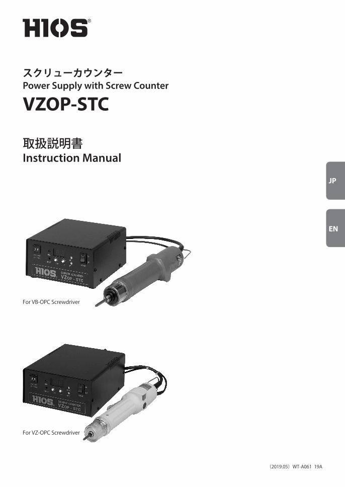
For VB-OPC Screwdriver
JP
EN
スクリューカウンターPower Supply with Screw Counter
VZOP-STC
取扱説明書Instruction Manual
(2019.05)WT-A061 19A
For VZ-OPC Screwdriver

2
VZOP-STC の概略ねじカウンターとは
電動ドライバーを使用してネジ締め作業をする場合、作業管理者は 1 つのワークに決められた本数のネジ締めが行われた事を確認し、ネジの締め忘れを未然に防ぐ必要があります。そこでドライバーからの OP 出力信号(正転信号・トルクアップ信号・逆転信号)を利用しネジの締め忘れを管理する為のカウンターが VZOP-STC です。VZOP-STC は外部機器を制御する為の電源(DC24V/0.3A)と外部機器制御用の入出力信号が内蔵されていますので、そのままインターロック用の電磁弁につなげるだけで作業者のポカミスを未然に防ぐ事ができます。
(ワークネジ締めが完了しなければワークが取り出せない様な治具を使用した場合)
またドライバーの逆転信号を入力する事によってネジを緩めた時にカウントを戻す(アップ)動作を選択出来ます。(モード SW3 で選択可能)ただし、ネジの噛みこみが発生した場合(通常カウントしない)逆転カウントアップする時間を設定出来る様にして有ります。0.2 ~ 1.0 秒で時間設定が可能、通常管理者のみが設定可能とする為、内蔵基板上の SW で設定します。出荷時は目盛 2に設定(0.2 秒)して有ります。(目盛り 1 は使用不可とします。)
注意:設定変更の際は危険ですので、絶対に電源コンセントを抜いてから作業してください。
セット信号は入力の立ち上がりでセットされますので、セル生産や屋台生産で一人の作業者が何台ものドライバーを使用する際に、実際に使用するドライバーのみが動作するといった作業者に頼らない管理ができます。ER BZ 出力はワーク確認 SWが作業中に OFF した時、未完成ワークが発生したことを知らせる信号です。リセットを入力するか、またネジ締めを完成させるまで出力します。作業者への警告ブザーを取り付けてご使用ください。
JP

3
VZOP-STC 仕様
入力電圧 AC100V ±5% 50/60Hz
電源容量 100W
ヒューズ容量 6A/250V(予備ヒューズ付き 1 ヶ)
寸法(W)×(D)×(H) 160×175×84 mm
重量 1.5Kg
AC コード長 1.8 m(アース付)
添付品 端子 8 ヶ、マイナスドライバー 1 本
色 黒(シルク:オレンジ)
対応ドライバー VB シリーズVB-1510-OPC/VB-1510-18-OPC/VB-1820-OPC/VB-3012-OPC/VB-3020-OPC
(PS式含む)
VB-4504PS-OPC
VZ シリーズVZ-1510-OPC/VZ-1820-OPC/VZ-3007-OPC/VZ-3012OPC
(PS式含む)
VZ-4506PS-OPC
JP
4
ご使用の際は電動ドライバーの取扱説明書をよくお読みいただき正しくご使用ください。
■設置場所について
1.使用する商用電源には、必ず漏電ブレーカー及びブレーカーを設置してください。
2.ホコリ、チリや金属片のかからない場所に設置してください。
3.水や油等のかからない場所に設置してください。
4.本機の上に重い物を置いたり、重ねたりはしないでください。
5.設置場所には振動のない、安定した場所を選んでください。
6.高いところに設置する場合は、本機をしっかり固定し、落下の危険がないようにしてください。
7.高電圧機器の近くや、ノイズの多い環境には設置しないでください。
8.入出力の配線は必要以上に長くしたり、電源線と束ねたりしないでください。誤動作の原因になりま
す。
■ご使用上の注意
1.本機はアースを接続して指定の定格電源、電圧でご使用ください。
2.リアパネル端子台の出力端子に接続する負荷は、定格負荷を超えないようにしてください。
3.リアパネル端子台の +DC24V 出力端子や入出力端子に接続する外部機器がリレーや電磁弁のコイ
ル等の電磁誘導負荷の影響を受ける場合は、逆電圧吸収用ダイオード等のノイズ対策を行ってく
ださい。ノイズ対策をしない場合は誤動作及び故障の原因になります。
4.リアパネル端子台の +24VDC 端子と各出力端子及び GND 端子は絶対に接続しないでください。
5.本機の機能を利用して外部機器を外部電源にて使用する場合は GND 端子を共通にしてください。
6.入力端子及び出力端子には電圧を加えないでください。電圧を加えた場合は故障の原因になりま
す。
7.使用温湿度は 5°C~40°C、80%以下(ただし、結露が無いこと)でご使用ください。
8.電源コードやドライバーコードを着脱する場合、必ずプラグ部分を持って行ってください。
9.コード類を引きずったり、油や鋭いエッジ等に触れたり、さらに重い物の下敷きにしないでくだ
さい。断線や故障の原因になります。
10.加熱やヒューズの溶断等の異常が発生した場合、直ちに使用を取りやめ電源メイン SW を切り、
電源コードをコンセントから抜いて、弊社サービス部までお出しください。
11.樹脂製品等の静電気を多く帯電しやすいワークのねじ締め作業の場合は、除電してから作業を
行ってください。除電しない場合はビット先端から静電気が流れ込み誤動作の原因になります。
12.落下等の強いショックを与えないでください。
13.弊社製対応ドライバー以外は絶対に接続しないでください。故障の原因になります。
14.長時間使用しない場合は電源メイン SW を “OFF” にして、電源からプラグを抜いてください。
15.お客様での分解や改造は絶対にしないでください。行った場合は故障の原因になります。この
場合は保証の適用除外や修理をお受けすることができません。
JP

5
メイン SWカウンターの電源の入り切りを行います。電源が入っているときに緑の LED 表示が点灯します。
リセットボタンネジカウントの設定中にまたは設定後に 1 クリックしてください。設定数が表示されます。リアパネル端子台のリセット信号と同じ働きをします。
動作表示 LEDリアパネル端子台のセット信号でセットされる電磁弁と同期して点灯します。
表示部設定されたネジ本数が表示されます。ネジ締めが進むにしたがってカウントダウンします。あと何
本で作業完了かが一目でわかります。
カウント設定 SWネジ締め本数を設定する SW で 1 本~ 99 本まで設定できます。1 の位 10 の位を別々に設定してください。設定中または設定後に必ずリセットボタンを 1 クリックして設定数を確認してください。設定には添付のマイナスドライバーでまわしてください。
カウントタイマーネジ締めで締めきったネジを再び締めつけた場合に誤カウントするのを防ぐ為のタイマーです。ご使用のドライバーで締めきったネジを締めつけながらカウントしない時間までデジタル SW で 1/100秒刻みで設定できます。(0.01 秒~1.00 秒)
ワークセットタイマーリアパネルの端子台のセット信号が入力されてから電磁弁等の働くまでの時間を調整します。(0.1秒~3 秒)
ワークリセットタイマー作業完了から電磁弁が切れるまでの時間を調整します。ブザー音と同期しています。(0.1 秒~3 秒)
※注意!! ボリュームや SW の設定の際は無理な力を加えないでください。故障の原因になりま
す。
フロントパネル
カウント設定SW
動作表示LED ワークセットタイマー
JP

6
リアパネル
COMP RESET SET GND
+DC24V VALVE BZ ER BZ
GND入力出力用 GND
SETワークがセットされた信号で GND とショートするとセットタイマーで設定された時間が経過すると、フロントパネル動作表示 LED が点灯し、VALVE 信号が ON します。
RESETワークが不良の場合など作業を中止する時に GND とショートするとリセットがかかります。
COMPねじ 締 め が 完 了し、ブ ザ ー が 鳴り終 った 後、0.1 秒 出 力します。( オ ープ ンコレ クター出 力 DC30V/0.1A)
ER BZ作業中に(ワーク完了前)、ワークを取り出すと作業完了またはリセットされるまで、出力します。エラー用のブザー等を接続し警告を出してください。
BZ最後のねじ締めが完了するとブザーと同期して出力される信号です。(オープンコレクター出力 DC30V/0.1A)
VALVEセット入力が入った後、電磁弁(DC24V)を動作させる時、使用します。電磁弁の + を +DC24V の端子台に接続し、GND 側を VALVE 端子に接続してください。その他電圧のものを使用する場合、GND を共通端子として外部電源を使用してください。(オープンコレクター出力 DC30V/0.1A)
+DC24V外部の機器を動作させるための電源です。電源容量は DC24V/0.3A です。
モード SW1:OFF にすると完了通知用ブザー音(内蔵)がしなくなります。2:OFF するとパネル表示が消えます。3:OFF すると逆転カウントアップの動作を止めます。4:OFF するとセット入力が入ってからしか動作しません。5:未使用
JP

7
基本的な使用方法使用例 1: 作業者がワークを置くとワークを電磁弁で固定され、ネジ締め作業が終了すると電磁弁が
開きワークが次の工程にまわされる場合(完了しない場合はワークは外れない)
1.ワークがセットされた時の信号をリアパネルの端子台のセット SET と GND 接続します。(接点の
場合は極性は無しオープンコレクターの場合は GND を共通にして SET に出力信号を接続してくだ
さい。)
2.リアパネル端子台の +DC24V に電磁弁の + を、VALUE に – を接続します。
3.作業中止やワーク固定解除の為の SW(接点)をリセットと GND につないでください。
4.ドライバーを接続しドライバーで締めきったネジを締めてもカウントダウンしない位置まで
CN-T 調整してください。
5.ワークが到着してから電磁弁の動作するまでの時間を WS-T で調整してください。
6.ネジ締めが完了してから電磁弁が OFF するまでの時間を WR-T で調整してください。
7.リアパネルの端子台の COMP 信号と GND に市販のカウンター等を接続し完成品のトータル数を
管理してください。
JP

8
基本的な使用方法使用例 2: 一人の作業者が 2 台のドライバーを使用し 2 種類のネジ締めをしている場合でワークは
固定しない。ただ、ドライバーは一方が動作しているときは他方は動作させたくない場
合。(VZOP-STC を 2 台使用してそれぞれを A・B とします。)
1.ワークがセットされた時の信号を、A のリアパネルの端子台のセット SET と GND 接続します。
(接点の場合は極性は無しオープンコレクターの場合は GND を共通にして SET に出力信号を接
続してください。)
2.A・B の GND をつなぎます(共通にする)
3.A の COMP と B の SET を接続します。
4.A のモード SW1 を OFF にします(A のブザーが鳴らない様にします)
5.B の COMP と GND にトータルカウンターを接続します。
JP

9
VZ ドライバー(正転・逆転・ねじ締め完了出力信号付き)について
タイミングチャート
■概略
VZ ドライバーに正転・逆転・ねじ締め完了出力信号を出力する回路を追加しました。配線は信号線 3 本と電源線 2 本の合計 5 本になります。出力はオープンコレクター出力(MAX24V/20mA)で、シーケンサー等にダイレクトに接続できます。
●注意点
・ドライバーの取扱い注意をよく守ってご使用ください。・信号線の逆接続は絶対にしないでください。・信号線に電源のプラス側を直接接続しないでください。・信号を誤配線しないでください。・信号線で許容値以上の電流電圧で使用しないでください。(リレー・モーター・ランプ等の制御には使用しないでください。)・ドライバーを 10SEC 以上回転させるような使用方法はしないでください。・ 正転・逆転の信号はスタート SW が OFF してもモーターの回転が停止するまで条件によって、出力される場
合があります。・正転/逆転の切り替えはドライバーの回転が完全に停止してから行ってください。・正転/逆転ともにトルク UP した場合は、トルク UP 信号が出ます。
配線色 回路構成
赤 +DC24V
黒 GND
緑 正転信号
白 トルク UP 信号
黄 逆転信号
■内部回路
JP

10
中国 RoHS2 について下記の表は中国 RoHS2 に関する表です。
中国に輸出される場合で中国税関から問合わせがある場合は、この表を提示してください。
有害物质名称及含量标识格式
产品中有害物质的名称及含量
部件名称有害物質
铅(pb) 汞(Hg) 镉(Cd)六价铬
(CR(VI))
多溴联苯
(PBB)
多溴二苯醚
(PBDE)
电路板总成 × ○ ○ ○ ○ ○
外壳 ○ ○ ○ ○ ○ ○
螺丝刀线 × ○ ○ ○ ○ ○
-
-
本表格依据 SJ/T 11364 的规定编制。
○: 表示该有害物质在该部件所有均质材料中的含量均在 GB/T 26572 规定的限量要求以下。
×: 表示该有害物质至少在该部件的某一均质材料中的含量超出 GB/T 26572 规定的限量要求。
また、別途に製品および製品の個装箱にも下記「中国 RoHS のマーク」が必要です。
万一、マークがない場合で緊急の際は、「中国 RoHS のマーク」を切り取り、製品および個装箱に貼
付してください。
あるいは、お手数でも弊社営業部までお問い合わせください。
「中国 RoHS のマーク」
JP

11
Outline of the VZOP-STC
When performing work that requires screws to be tightened with an electronic screwdriver, the
operator must check that the correct number of screws has been used for a particular piece of
work in order to prevent the work piece leaving with screws that have not been tightened.
The VZOP-STC screw counter makes use of the OP output signals (normal rotation signal, torque
up signal, reverse rotation signal) from the screwdriver to allow the operator to check if any screws
require tightening.
The VZOP-STC features a power source (DC 24 V / 0.3 A) to power external equipment as well as an
input/output signal to control them. As such, the unit can be connected directly to an interlocking
solenoid valve to prevent careless mistakes made by the operator.
(When using a jig that prevents removal of the work piece before the all screws are fully
tightened)
The operator can also select a function that reverses (increases) the count if a reverse signal is
input to the screwdriver to loosen the screws (selected with mode SW3).
Another option allows the reverse count up time to be set when screws are biting (normally not
counted). This time can be set between 0.2 and 1.0 seconds. A switch has been installed on the
internal circuit board to allow the normal operator to change the settings. The factory default
setting is level 2 (0.2 seconds) (level 1 cannot be used).
Note: Changing the settings can be dangerous. Only change settings after removing the power plug.
The SET signal is set when power is supplied to the unit, meaning that it is possible to provide
effective management that is not reliant on the operator during cell production when one
operator is required to uses several screwdrivers. The ER BZ output signal warns of the presence of
incomplete work when the work check switch is OFF. The unit may be reset or the signal will be
output until the work is completed. This signal can be used by attaching a warning buzzer to warn
the operator.
EN

12
VZOP-STC Specifications
Input voltage AC 100 V ±5% 50/60 Hz / AC 120 V 50/60Hz
Power capacity 100 W
Fuse capacity 6 A / 250 V (with one spare fuse)
Dimensions(W)×(D)×(H)
160×175×84 mm
Weight 1.5Kg
AC cord length 1.8m (with ground)
Supplied accessories 8 terminals, 1 slotted screwdriver
Compatible drivers VB-OPC specification driverVB-1510-OPC/VB-1510-18-OPC/VB-1820-OPC/VB-3012-OPC/VB-3020-OPC(Including PS type)VB-4504PS-OPC
VZ-OPC specification driverVZ-1510-OPC/VZ-1820-OPC/VZ-3007-OPC/VZ-3012-OPC(Including PS type)VZ-4506PS-OPC
EN

13
Please read through the electronic screwdriver instruction manual carefully before use and use only as per instructions.
■ Installation area1. Always install a ground leakage breaker and safety breaker to commercial power supplies.2. Install the unit in an area that is not subjected to dust, dirt or metal fragments.3. Install the unit in an area that is not subjected to water or oil.4. Do not place heavy items on top of the unit or stack units on top of one another.5. Select a safe installation area that is free from vibration.6. If the unit is to be installed in an elevated location, ensure that it is fixed firmly so that there is no danger
of the unit falling.7. Do not install the unit near other high-voltage equipment or electronically noisy environments.8. Do not use input and output cables that are longer than required or knot them. Doing so may result in
incorrect reading.
■ Precautions for use1. Ensure that the unit is grounded and that the specified rated power and voltage are used.2. Ensure that loads connected to the output terminals on the rear panel terminal block do not exceed the
rated load.3. If external equipment connected to the +DC 24 V output terminal or input/output terminals on the rear
panel terminal block are affected by the electromagnetic induction of relays and solenoid valves coils, noise prevention in the form of reverse voltage absorbing diodes should be used. Equipment may operate incorrectly or malfunction if noise prevention is not used.
4. Do not connect the +24 V DC terminals on the rear panel terminal block to any output terminal or GND terminal.
5. If the unit’s functions are used to power external equipment with an external power source, a common GND terminal should be used. Equipment may operate incorrectly or malfunction if a common GND is not used.
6. Do not provide additional voltage to the input or output terminals. Additional voltage will result in a malfunction.
7. Use the unit in temperatures of 5°C to 40°C and 80% or less humidity (with no condensation).8. Always hold the plug when connecting or removing the power cord or driver cord.9. Do not pull the cords, drag them across oil or sharp edges, or place heavy objects on top of them. Doing
so may result in severed wires or malfunctions.10. If a malfunction occurs and the unit overheats or the fuse blows, stop using the unit immediately and
turn off the main power switch, remove the power cord from the power outlet and bring the unit to our service department.
11. When tightening screws on plastic work pieces that may have a lot of static electricity buildup, remove electricity before starting work. If electricity is not removed, static electricity may flow from the end of bit, resulting in incorrect operation.
12. Do not drop or subject the unit to strong shocks.13. Do not use drivers other than those manufactured by HIOS. Doing so may result in a malfunction.14. Turn the main power switch OFF if the unit is not used for a prolonged period of time, and remove the
power plug.15. Never dismantle or modify the unit by yourself. Doing so may result in a malfunction and void the
warranty or make it impossible to be repaired.
EN

14
Main SWTurns the power to the counter on and off. The LED display will turn green when the power is on.
Reset ButtonClick once during or after setting the screw count. The set value will be displayed. This has the same function as the reset signal on the rear panel terminal block.
Operating Display LEDLights up when solenoid valves have been set by the set signal on the rear panel terminal block.
DisplayDisplays the set number of screws. The number counts down as screws are tightened and show how many screws are remaining.
Count Set SWThis switch sets the number of screws to be tightened, and can be set from 1 to 99 screws. Set units of 10 and 1 individually. Click the reset button once during or after setting the number of screws to confirm the screw count. Rotate the supplied slotted screwdriver to change settings.
Count TimerThis timer prevents incorrect screw counts when tightening a screw that has already been tightened a second time. Use the digital switch to set the time in 1/100 increments to be ignored for the count when using the driver to tighten screws that have already been tightened (0.01 to 1.00 seconds).
Work Set TimerAdjusts for the time between the input set signal on the rear panel terminal block and start of operation of the solenoid valve (0.1 to 3 seconds).
Work Reset TimerAdjusts for the time between the completion of work and when the solenoid valve turns off. A buzzer sounds at the same time (0.1 to 3 seconds).
*Caution!!Do not apply excessive force when setting volume knobs or switches. Doing so may result in a malfunction.
Front Panel
Display Work Set Timer
Main switch
Work Reset Timer
Count Set Switch
Count Timer
Reset Button
Operating Display LED
EN

15
Rear Panel
GNDGND for input and output.
SETThe Operating Display LED on the front panel will light up and the VALVE signal turned ON when the signal received from the external switch when the work is set is shorted to ground and the time set on the set timer elapses.
RESETThe unit is reset when work is stopped as a result of defective work and GND is shorted.
COMPOutput will continue for 0.1 seconds after the screws have been tightened and the buzzer has finished sounding. (Open collector output DC 30 V / 0.1A)
ER BZOutput will continue until work is complete or the unit is reset when the work piece is removed during operations (before work is complete). A warning can be generated by connecting an error buzzer.
BZA signal generated in time with the buzzer when the final screw has been tightened (open collector output DC 30 V / 0.1A).
VALVEUsed after the set input signal has been received and the solenoid valve (DC 24 V) has started operating. Connect the + terminal of the solenoid valve to the +DC 24 V terminal block and – terminal to the VALVE terminal on the rear panel. If other voltages are used, use an external power source with a common GND terminal (open collector output DC 30 V / 0.1A).
+DC24VPower source for powering external equipment. The power capacity is DC 24 V / 0.3A.
Mode Switches1: The work complete notification buzzer (built in) no longer sounds if switched OFF.2: The panel display turns off if switched OFF.3: The reverse rotation count up operation turns off if switched OFF.4: When switched OFF, the unit will only work once the set input signal is received.5: Unused.
COMP RESET SET GND
+DC24V VALVE BZ ER BZ
For VB-OPC driver or VZ-OPC driver 100V output socketMode Switch Terminal Block
Fuse holder
AC inletConnector for OPC drivers Signal cord
EN

16
Basic Operations
Example 1: When a solenoid valve is used to hold work placed by the operator on the bench and the work is released by the valve and moves to the next production process once all screws have been tightened. (The work piece is not released until all screws have been tightened).
1. Connect the external switch to SET and GND on the rear panel terminal block (no polarity if an external switch is used and common GND if an open collector is used before connecting the output signal to SET).
2. Connect the + terminal of the solenoid vale to +DC 24 V, and – terminal to VALVE on the rear panel terminal block.
3. Connect the switch (contact point) for releasing the work if operations are stopped to RESET and GND.4. Connect the driver and adjust CN-T to a position that does not count down even if the driver is used to
further tighten screws that have already been tightened.5. Adjust WS-T to the time taken for the solenoid valve to operate after the work piece arrives.6. Adjust WR-T to the time taken to turn the solenoid valve OFF after all screws have been tightened.7. Connect a commercially available counter to the COMP signal and GND on the rear panel terminal block
to manage the total number of completed work pieces.
Total Counter
Work Detection Switch
Work Rest Switch
Solenoid Valve
EN

17
Basic Operations
Example 2: When one operator is using two drivers and two varieties of screws and the work piece is not secured. When you only want to use one driver. (2 VZOP-STC units are being used and are named A & B respectively)
1. Connect the external switch to SET and GND on the rear panel terminal block ((no polarity if an external switch is used and common GND if an open collector is used before connecting the output signal to SET).
2. Connect both A and B GND (common GND).3. Connect A COMP and B SET.4. Set A mode SW1 to OFF (so that the buzzer for A does not sound).5. Connect a total counter to B COMP and GND.
Work Detection Switch
Work Rest Switch
Total Counter
EN

18
Regarding the VZ Screwdriver (with output signals for forward & reverse rotations and screw tightening completion)
Timing Chart
■ OverviewWe added a circuit for output signals of forward & reverse rotations and screw tightening completion to the
VZ screwdriver.
The wiring consists of five in total: three for signals and two for power.
The output type is open collector output (MAX 24 V / 20 mA) and can be connected directly to a sequencer
and others.
● Cautions for handling・Always handle with care when you use the screwdriver.
・In any circumstances, do not connect the signal wire in reverse.
・Do not connect the positive side of the power supply directly to the signal wire.
・Make sure the wiring of the signal wires are correct.
・Do not use power beyond the allowable amperage/voltage for the signal wire.
(Do not use this device to control relays, motors, lamps, and so forth.)・Do not rotate the screwdriver for more than 10 seconds.
・ There may be cases where the signal for forward or reverse rotation signals are continually sent until the motor stops
rotating even after the Start SW is turned off.
・Therefore, confirm that the rotation is completely stopped before switching from forward and reverse rotations.
・If there is an increase in the torque in the forward/reverse rotation, the torque UP signal will be sent.
Wiring color Circuit configuration
Red +DC24V
Black GND
Green Forward rotation signal
White Torque UP signal
Yellow Reverse rotation signal
Start SW
Torque UP
FOR/REV SW
Motor's rotational direction
FOR
REV
Forward rotation signal
Reverse rotation signal
Screw tightening completion signal
FOR REV
About 80 seconds per shot About 80 seconds per shot
+DC24V
Internal circuit
GND
Signals
■ Internal circuit
EN

19
China RoHS2 Table
If you are asked by China Customs, please show this table to them.
有害物质名称及含量标识格式
产品中有害物质的名称及含量
部件名称有害物質
铅(pb) 汞(Hg) 镉(Cd)六价铬
(CR(VI))
多溴联苯
(PBB)
多溴二苯醚
(PBDE)
电路板总成 × ○ ○ ○ ○ ○
外壳 ○ ○ ○ ○ ○ ○
螺丝刀线 × ○ ○ ○ ○ ○
-
-
本表格依据 SJ/T 11364 的规定编制。
○: 表示该有害物质在该部件所有均质材料中的含量均在 GB/T 26572 规定的限量要求以下。
×: 表示该有害物质至少在该部件的某一均质材料中的含量超出 GB/T 26572 规定的限量要求。
In addition, the China RoHS marks also is required at the product and product box.At the product, you can find it at the bottom and it is marked on the product box.If you cannot find the mark, please ask your distributor.In case of emergency, please cut the mark below and stick at the bottom of product and on the product box.
China RoHS mark
Note: minimum size of China RoHS mark is 5mm at outer diameter
EN

1-35-1 Oshiage, Sumidaku-ku Tokyo, JapanTEL: 81 (Japan) 3-6661-8821
HIOS Inc.株式会社
東京都墨田区押上 1-35-1TEL:03-6661-8777

![[スバル]CVT 学習作業 例:レヴォーグ VM4 BRM...[スバル]CVT 学習作業 (例:レヴォーグ VM4、レガシー BRM) [スバル] CVT 学習作業 (例:レヴォーグ](https://img.pdfslide.tips/doc/110x75/5e39df3ea77ba259162ec994/ffcvt-coe-ifff-vm4-ffcvt-coe.jpg)