Embed Size (px)
Citation preview
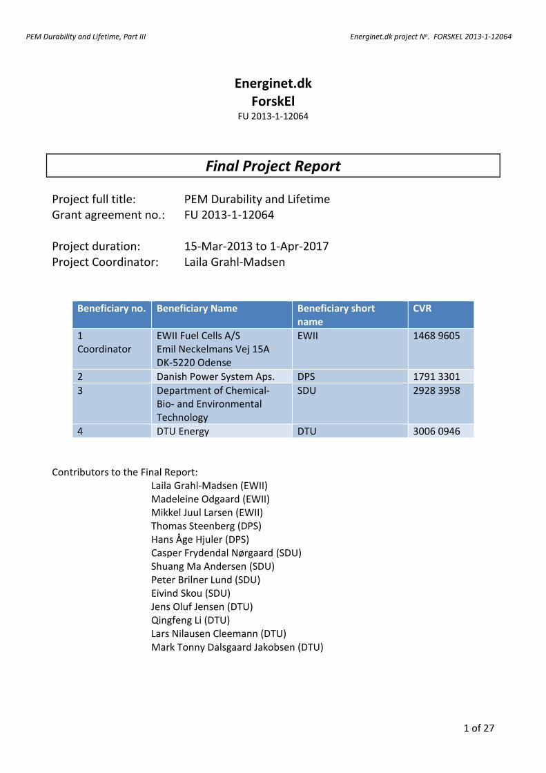
PEM Durability and Lifetime, Part III Energinet.dk project No. FORSKEL 2013-1-12064
1 of 27
Energinet.dk ForskEl
FU 2013-1-12064
Final Project Report
Project full title: PEM Durability and Lifetime Grant agreement no.: FU 2013-1-12064 Project duration: 15-Mar-2013 to 1-Apr-2017 Project Coordinator: Laila Grahl-Madsen
Beneficiary no. Beneficiary Name Beneficiary short name
CVR
1 Coordinator
EWII Fuel Cells A/S Emil Neckelmans Vej 15A DK-5220 Odense
EWII 1468 9605
2 Danish Power System Aps. DPS 1791 3301
3 Department of Chemical- Bio- and Environmental Technology
SDU 2928 3958
4 DTU Energy DTU 3006 0946
Contributors to the Final Report: Laila Grahl-Madsen (EWII) Madeleine Odgaard (EWII) Mikkel Juul Larsen (EWII) Thomas Steenberg (DPS) Hans Åge Hjuler (DPS) Casper Frydendal Nørgaard (SDU) Shuang Ma Andersen (SDU) Peter Brilner Lund (SDU) Eivind Skou (SDU) Jens Oluf Jensen (DTU) Qingfeng Li (DTU) Lars Nilausen Cleemann (DTU) Mark Tonny Dalsgaard Jakobsen (DTU)
PEM Durability and Lifetime, Part III Energinet.dk project No. FORSKEL 2013-1-12064
2 of 27
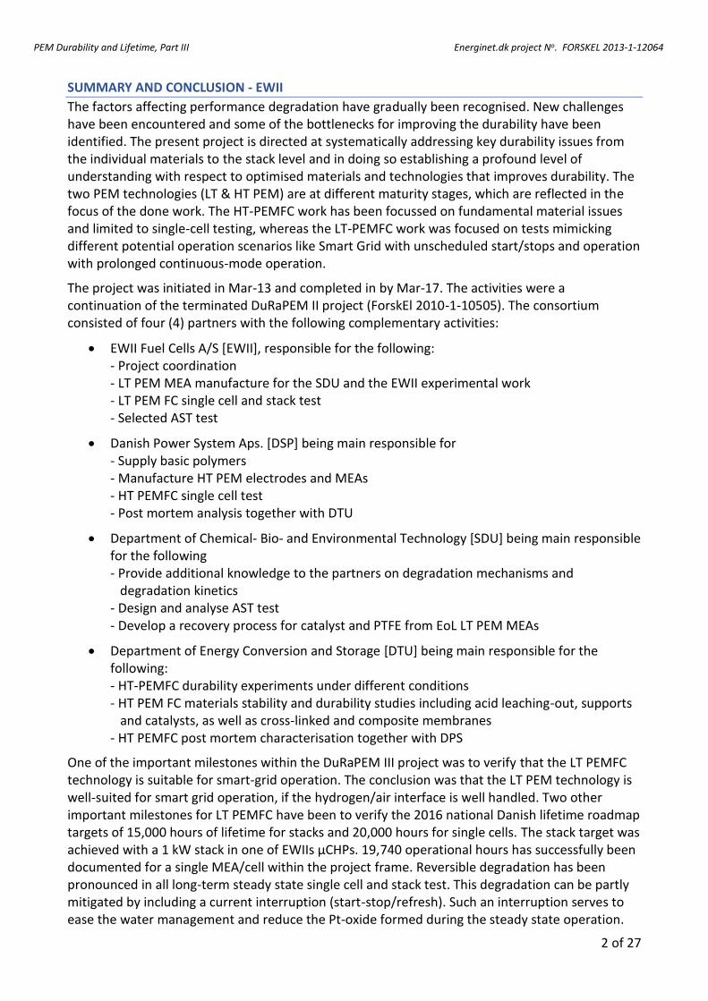
SUMMARY AND CONCLUSION - EWII
The factors affecting performance degradation have gradually been recognised. New challenges have been encountered and some of the bottlenecks for improving the durability have been identified. The present project is directed at systematically addressing key durability issues from the individual materials to the stack level and in doing so establishing a profound level of understanding with respect to optimised materials and technologies that improves durability. The two PEM technologies (LT & HT PEM) are at different maturity stages, which are reflected in the focus of the done work. The HT-PEMFC work has been focussed on fundamental material issues and limited to single-cell testing, whereas the LT-PEMFC work was focused on tests mimicking different potential operation scenarios like Smart Grid with unscheduled start/stops and operation with prolonged continuous-mode operation.
The project was initiated in Mar-13 and completed in by Mar-17. The activities were a continuation of the terminated DuRaPEM II project (ForskEl 2010-1-10505). The consortium consisted of four (4) partners with the following complementary activities:
EWII Fuel Cells A/S [EWII], responsible for the following: - Project coordination - LT PEM MEA manufacture for the SDU and the EWII experimental work - LT PEM FC single cell and stack test - Selected AST test
Danish Power System Aps. [DSP] being main responsible for - Supply basic polymers - Manufacture HT PEM electrodes and MEAs - HT PEMFC single cell test - Post mortem analysis together with DTU
Department of Chemical- Bio- and Environmental Technology [SDU] being main responsible for the following - Provide additional knowledge to the partners on degradation mechanisms and degradation kinetics - Design and analyse AST test - Develop a recovery process for catalyst and PTFE from EoL LT PEM MEAs
Department of Energy Conversion and Storage [DTU] being main responsible for the following: - HT-PEMFC durability experiments under different conditions - HT PEM FC materials stability and durability studies including acid leaching-out, supports and catalysts, as well as cross-linked and composite membranes - HT PEMFC post mortem characterisation together with DPS
One of the important milestones within the DuRaPEM III project was to verify that the LT PEMFC technology is suitable for smart-grid operation. The conclusion was that the LT PEM technology is well-suited for smart grid operation, if the hydrogen/air interface is well handled. Two other important milestones for LT PEMFC have been to verify the 2016 national Danish lifetime roadmap targets of 15,000 hours of lifetime for stacks and 20,000 hours for single cells. The stack target was achieved with a 1 kW stack in one of EWIIs µCHPs. 19,740 operational hours has successfully been documented for a single MEA/cell within the project frame. Reversible degradation has been pronounced in all long-term steady state single cell and stack test. This degradation can be partly mitigated by including a current interruption (start-stop/refresh). Such an interruption serves to ease the water management and reduce the Pt-oxide formed during the steady state operation.
PEM Durability and Lifetime, Part III Energinet.dk project No. FORSKEL 2013-1-12064
3 of 27
Recovery of platinum directly from EoL LT PEMFC MEA has been disregarded since the PGM yields were low. Instead, the focus has been shifted to recover the platinum in an electrochemical fluidised bed reactor. The preparation for recovery in an electrochemical fluidised bed reactor involves the separation of the MEA in an alcoholic solution into its constituent electrodes and the membrane. Both electrodes and the PFSA-membrane contain platinum and need to be further processed before recovery can be made. The electrodes need to be scraped (planed) and the carbonaceous fraction can be added to dilute hydrochloric acid (1 M) from which the recovery can be made. Dispersing the agglomerates may be necessary in order to facilitate better recovery from the suspension. The membrane needs to be dissolved in the alcoholic solution from which the electrodes were separated. Upon dissolution, the liquid will contain platinum particles and its constituent carbon support and usually, but not always, the PTFE net, which stabilises the membrane mechanically. After removal of the PTFE net, the suspension is centrifuged and the sedimented particles can be merged with the suspension from the electrodes. The dissolved Nafion™ is then concentrated by evaporation and may be re-used as an ionomer. Platinum and ruthenium can be dissolved electrochemically in hydrochloric acid to produce the corresponding chloro-complexed ion. These ions can be filtered by means of diffusion through a membrane in the electrochemical fluidized bed reactor. The platinum can then be concentrated approximately 10 – 100 times in another filter in order to achieve a clean, concentrated solution. The results from these small-scale experiments indicate >90% PGM recovery and recovery of a substantial part of the PFSA-ionomer. The developed PGM recovery technique has been patented.
HT PEMFC MEAs based on cross-linked PBI membranes have proved to possess superior durability
compared to MEAs based on standard PBI. The overall cell performance was 20 mV lower at BoL for the MEAs based on cross-linked membrane, likely due to the slight differences in acid doping level, but the long-term tested MEA (+9,000 h’s) based on the crosslinked membrane type exhibited a superior low degradation rate of only 0.5 µV/h, which is much lower than the other samples evaluated also lower than reported in literature. Composite PBI membranes with 0-15 wt% functional filler has been investigated for acid uptake, performance, and durability including AST investigations incorporating elevated temperatures as the primary stressor. The results show improved durability of MEAs based on composite membranes with 15 wt% PWA-meso-SiO2. It is very likely that incorporating this type of filler into the membrane leaves the MEA more tolerant towards high temperature operation because the composite MEAs are less influenced by phosphoric acid leaching and membrane dehydration.
Novel more hydrophobic electrodes has been developed for HT PEMFC MEAs. This has proven to reduce the acid loss (performance loss) due to start/stop (water condensation and wash out of phosphoric acid) events when fed with wet fuel like reformate. 17,000 hours of long-term single cell HT PEMFC durability test have shown a significant increase in degradation after 12,000 h. The post mortem analysis after EoT showed noteworthy thinning of the membrane, low content of phosphoric acid and growth of the Pt-particles in the catalyst layer. This can be partly mitigated by increasing both the membrane thickness and the doping level on MEAs based on thermally treated PBI. A MEA reproducibility study has demonstrated insignificant variations between three (3) consecutive MEA batches from the production.
The project results have been widely disseminated. The results have made base for 38 papers in peer reviewed journals, two (2) chapters in scientific books, seven (7) invited/keynote-speech conference contributions, and (1) patent.
PEM Durability and Lifetime, Part III Energinet.dk project No. FORSKEL 2013-1-12064
4 of 27
TABLE OF CONTENT
1. Introduction .................................................................................................................. 5
1.1 Preface ............................................................................................................................. 5
1.2 Project Objectives ............................................................................................................ 5
1.3 State-of-the-art at Project Start ....................................................................................... 5
1.4 Project Overview .............................................................................................................. 8
2. LT PEM - EWII ................................................................................................................ 9
2.1 AST tests ........................................................................................................................... 9
2.2 LT PEMFC Steady State Test ............................................................................................. 9
2.3 LT PEM Smart-Grid Capability ........................................................................................ 11
3. Component recovery and ex-situ test - SDU ................................................................. 13
3.1 Separation ...................................................................................................................... 13
3.2 Removal .......................................................................................................................... 13
3.3 Electrochemical dissolution ........................................................................................... 13
3.5 Conclusion ...................................................................................................................... 15
4. HT-PEM ....................................................................................................................... 16
4.1 Results and work done at DTU ....................................................................................... 16
4.2 Results and work done at DPS ....................................................................................... 19
5. Dissemination ............................................................................................................. 22
6. References .................................................................................................................. 26
7. Abbreviations .............................................................................................................. 27
PEM Durability and Lifetime, Part III Energinet.dk project No. FORSKEL 2013-1-12064
5 of 27
1. INTRODUCTION
1.1 PREFACE The present project is a continuation of the PSO project “PEM Durability and Lifetime, Part II” (FU 2010-1-10505) that was terminated in Dec-2013.
1.2 PROJECT OBJECTIVES An improved understanding of the main degradation issues of the PEMFC1 has been obtained in previous projects, e.g. DuRaPEM II.2 Single cells have been operated in excess of 10,000 hours, but with unacceptably high degradation rates. The objective of the DuRaPEM III project was to further quantify the issues limiting the durability. The main focus was to increase the durability for stationary applications operating in a Smart Grid and/or continuous-mode scenario. The two (2) Danish PEMFC technology tracks (LT- & HT-PEMFC) are both an integrated part of the project to ensure maximum synergy.
1.3 STATE-OF-THE-ART AT PROJECT START
1.3.1 LT PEM FC - EWII The fuel-cell industry has reached many milestones and accomplishments in the past decade. The main barriers for widespread commercialisation of fuel cells are still durability and cost. The factors affecting performance degradation have gradually been recognised. The most important being catalyst particle ripening (particle coalescence), preferential alloy dissolution in the catalyst layer, carbon-support oxidation (corrosion), catalyst poisoning, membrane thinning and pinhole formation, loss of active acid groups in the ionomer phase of the catalyst layer and/or in the membrane, bipolar plate surface film growth, hydrophilicity/porosity changes in the catalyst layer and/or gas diffusion layer (GDL), and PTFE decomposition in the catalyst layer and/or GDL. However, a substantial cost reduction has been achieved due to the continuous decrease in the platinum group metal (PGM) loading in PEM. The PGM loading has decreased by two orders of magnitude since the 1960s due to major development efforts in electrocatalyst fabrication and nanotechnology1. The PGM loading tends to continue to decrease to ultra-low loadings, which induces further durability challenges. Novel materials, designs and operation strategies still need to be combined to mitigate the insufficient lifetime, durability and reliability.
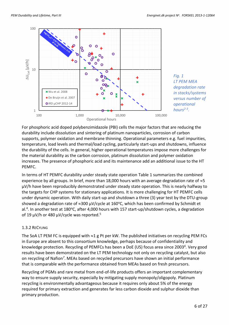
The literature on long-term LT PEMFC stack test is limited. However, the indication from both the literature and at EWII is that the MEA decay rate is decreasing with increasing operational hours (Fig. 1). One of the important milestones for EWII within the DuRaPEM III project was to verify the 2016 Danish national lifetime target for LT PEMFC stacks (15,000 h) not only at a theoretical level, but with a real life laboratory test.
1.3.2 HT PEM FC
After extensive work by the Danish as well as researchers from all over the world, HT PEMFC durability has been demonstrated. Degradation mechanisms of individual components as well as the entire cell performance have been well recognized.
1 Abbreviations are listed in Appendix C 2 PEM Durability and Lifetime – Part II (Energinet.dk J. No 2010-1-10505)
PEM Durability and Lifetime, Part III Energinet.dk project No. FORSKEL 2013-1-12064
6 of 27
1
10
100
100 1,000 10,000 100,000
DU
Cel
l[µ
V/h
]
Operational hours
Wu et al. 2008
De Bruijn et al. 2007
IRD µCHP 2012-14
Fig. 1 LT PEM MEA degradation rate in stacks/systems versus number of operational hours2-3.
For phosphoric acid doped polybenzimidazole (PBI) cells the major factors that are reducing the durability include dissolution and sintering of platinum nanoparticles, corrosion of carbon supports, polymer oxidation and membrane thinning. Operational parameters e.g. fuel impurities, temperature, load levels and thermal/load cycling, particularly start-ups and shutdowns, influence the durability of the cells. In general, higher operational temperatures impose more challenges for the material durability as the carbon corrosion, platinum dissolution and polymer oxidation increases. The presence of phosphoric acid and its maintenance add an additional issue to the HT PEMFC.
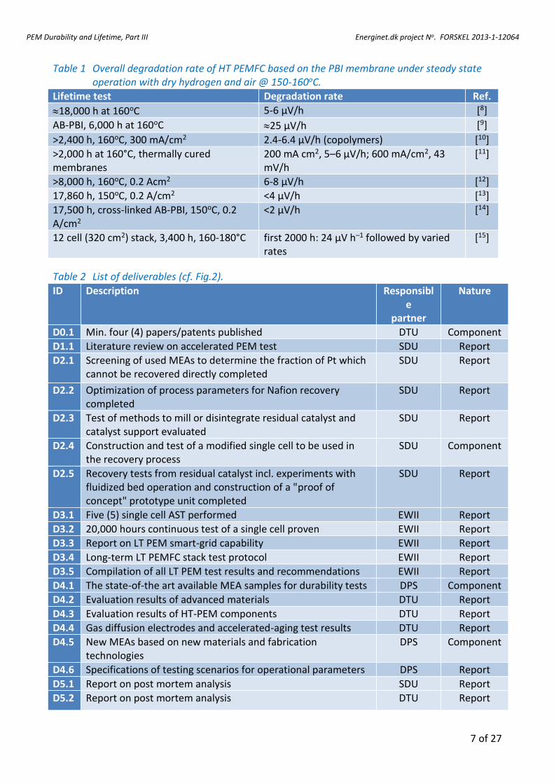
In terms of HT PEMFC durability under steady state operation Table 1 summarizes the combined
experience by all groups. In brief, more than 18,000 hours with an average degradation rate of 5 µV/h have been reproducibly demonstrated under steady state operation. This is nearly halfway to the targets for CHP systems for stationary applications. It is more challenging for HT PEMFC cells under dynamic operation. With daily start-up and shutdown a three (3) year test by the DTU-group
showed a degradation rate of 300 µV/cycle at 160oC, which has been confirmed by Schmidt et al.4. In another test at 180oC, after 4,000 hours with 157 start-up/shutdown cycles, a degradation of 19 µV/h or 480 µV/cycle was reported.5
1.3.2 RECYLING
The SoA LT PEM FC is equipped with 1 g Pt per kW. The published initiatives on recycling PEM FCs in Europe are absent to this consortium knowledge, perhaps because of confidentiality and knowledge protection. Recycling of PEMFCs has been a DoE (US) focus area since 20036. Very good results have been demonstrated on the LT PEM technology not only on recycling catalyst, but also on recycling of Nafion7. MEAs based on recycled precursors have shown an initial performance that is comparable with the performance obtained from MEAs based on fresh precursors.
Recycling of PGMs and rare metal from end-of-life products offers an important complementary way to ensure supply security, especially by mitigating supply monopoly/oligopoly. Platinum recycling is environmentally advantageous because it requires only about 5% of the energy required for primary extraction and generates far less carbon dioxide and sulphur dioxide than primary production.
PEM Durability and Lifetime, Part III Energinet.dk project No. FORSKEL 2013-1-12064
7 of 27
Table 1 Overall degradation rate of HT PEMFC based on the PBI membrane under steady state operation with dry hydrogen and air @ 150-160oC.
Lifetime test Degradation rate Ref.
18,000 h at 160oC 5-6 µV/h [8]
AB-PBI, 6,000 h at 160oC 25 µV/h [9]
>2,400 h, 160oC, 300 mA/cm2 2.4-6.4 µV/h (copolymers) [10]
>2,000 h at 160°C, thermally cured membranes
200 mA cm2, 5–6 µV/h; 600 mA/cm2, 43 mV/h
[11]
>8,000 h, 160oC, 0.2 Acm2 6-8 µV/h [12]
17,860 h, 150oC, 0.2 A/cm2 <4 µV/h [13]
17,500 h, cross-linked AB-PBI, 150oC, 0.2 A/cm2
<2 µV/h [14]
12 cell (320 cm2) stack, 3,400 h, 160-180°C first 2000 h: 24 µV h–1 followed by varied rates
[15]
Table 2 List of deliverables (cf. Fig.2).
ID Description Responsible
partner
Nature
D0.1 Min. four (4) papers/patents published DTU Component
D1.1 Literature review on accelerated PEM test SDU Report
D2.1 Screening of used MEAs to determine the fraction of Pt which cannot be recovered directly completed
SDU Report
D2.2 Optimization of process parameters for Nafion recovery completed
SDU Report
D2.3 Test of methods to mill or disintegrate residual catalyst and catalyst support evaluated
SDU Report
D2.4 Construction and test of a modified single cell to be used in the recovery process
SDU Component
D2.5 Recovery tests from residual catalyst incl. experiments with fluidized bed operation and construction of a "proof of concept" prototype unit completed
SDU Report
D3.1 Five (5) single cell AST performed EWII Report
D3.2 20,000 hours continuous test of a single cell proven EWII Report
D3.3 Report on LT PEM smart-grid capability EWII Report
D3.4 Long-term LT PEMFC stack test protocol EWII Report
D3.5 Compilation of all LT PEM test results and recommendations EWII Report
D4.1 The state-of-the art available MEA samples for durability tests DPS Component
D4.2 Evaluation results of advanced materials DTU Report
D4.3 Evaluation results of HT-PEM components DTU Report
D4.4 Gas diffusion electrodes and accelerated-aging test results DTU Report
D4.5 New MEAs based on new materials and fabrication technologies
DPS Component
D4.6 Specifications of testing scenarios for operational parameters DPS Report
D5.1 Report on post mortem analysis SDU Report
D5.2 Report on post mortem analysis DTU Report
PEM Durability and Lifetime, Part III Energinet.dk project No. FORSKEL 2013-1-12064
8 of 27
Fluoropolymers, like PGM’s, constitute a significant part of PEM devices. In both LT PEM electrolysers and fuel cells the electrolyte is (almost) always made of perfluorinated sulfonic acid (PFSA) polymers which is also present in the catalyst layers. Teflon™ is present in both LT- and HT PEM-devices and is primarily (but not exclusively) responsible for providing hydrophobicity in the Gas Diffusion Layer (GDL). The traditional way of separating fluoropolymers from the PGM’s has been to incinerate the entire FC thereby releasing toxic hydrofluoric fumes. Since especially PFSA polymers are costly to produce, incineration not only loses the inherent value of the PFSA polymers but also generates additional environmental burdens.
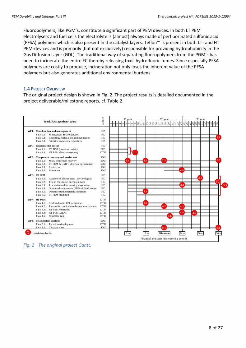
1.4 PROJECT OVERVIEW The original project design is shown in Fig. 2. The project results is detailed documented in the project deliverable/milestone reports, cf. Table 2.
1 2 3 4 5 6 7 8 9 10
11
12
13
14
15
16
17
18
19
20
21
22
23
24
25
26
27
28
29
30
31
32
33
34
35
36
WP 0: Coordination and management IRD
WP 1: Experimental design IRD
WP 2: Component recovery and ex-situ test SDU
WP 3: LT PEM IRD
WP 4: HT PEM DTU
WP 5: Post Mortem analysis SDU
: see deliverable list
Task 5.1: Technique development DTU
Task 3.4: Optimised components [MEA & Stack components]IRD
Financial and scientific reporting periods
30 m6 m 12 m 36 m
Task 5.2: Chacterisation SDU
Task 4.1: Acid leaching in PBI membranes DTU
Task 3.6: LT PEM Stack test IRD
Task 3.5: Optimise stack operating conditions IRD
Task 3.3: Test optimized for smart grid operation IRD
Task 3.2: Test in continuous operation mode IRD
Task 3.1: Accelerated lifetime tests - dry feed gases IRD
Task 2.4: SDUEvaluation
Task 2.2: LT PEM & DMFC electrode optimisation SDU
Task 2.1: MEA component recovery SDU
Task 1.3: HT PEM (literature review) DTU
Task 1.1: LT PEM (literature review) IRD
Task 0.3: Scientific know-how repatriates IRD
Task 0.2: Reporting, exploitation, and publication IRD
Task 0.1: Management & Coordination
3rd
yearWork Package descriptions
Lead
er
1st
year 2nd
year
IRD
Task 2.3: Ex-situ test SDU
Mid-term 24 m
Task 4.5: Durability test DTU
Task 4.4: HT PEM MEAs DTU
Task 4.3: HT PEM electrodes DTU
Task 4.2: Thermal & chemical membrane characterisation DTU
X
1.1
3.1
3.2
3.3 3.5
4.1
4.2 4.3
4.4 4.54.6
3.4
2.1 2.32.2 2.5
2.4
0.1
5.1 5.2
Fig. 2 The original project Gantt.
PEM Durability and Lifetime, Part III Energinet.dk project No. FORSKEL 2013-1-12064
9 of 27
2. LT PEM - EWII
2.1 AST TESTS
Five (5) LT PEMFC membrane AST are done using the most recent DoE protocol from January 2016. The results can be categorised in the following two (2) groups (Table 3):
AST of two (2) MEAs based on the traditional non-reinforced PFSA-membrane. One (1) of these has a SnO2 ion-exchanged anode the other not (the SnO2-ion exchange has been done at SDU)
AST of three (3) novel reinforced PFSA-membranes
Table 3 List of the tested PFSA membranes/MEAs.
Table 4 Change in electrochemical surface area (ECSA) and crossover before and after the membrane AST-test.
The AST protocol implies a 500 h OCV test of MEAs based on these membranes. The membrane durability is then mainly judged on the hydrogen crossover development. The test show that the MEA based on non-reinforced and non-ion-exchanged anode is significantly less durable than the other four (4) membranes investigated (Table 4). The H2 crossover developed by the MEAs based on the SnO2 exchanged anode and the reinforced membranes are almost identical and well within the acceptable range.
2.2 LT PEMFC STEADY STATE TEST
Several MEAs has been tested, some for screening precursors, some for AST and some for shorter time to investigate a specific operational pattern; some MEAs has been tested for prolonged time. A specific project target has been to verify 20,000 operational hours at single cell level. All LT
PEM Durability and Lifetime, Part III Energinet.dk project No. FORSKEL 2013-1-12064
10 of 27
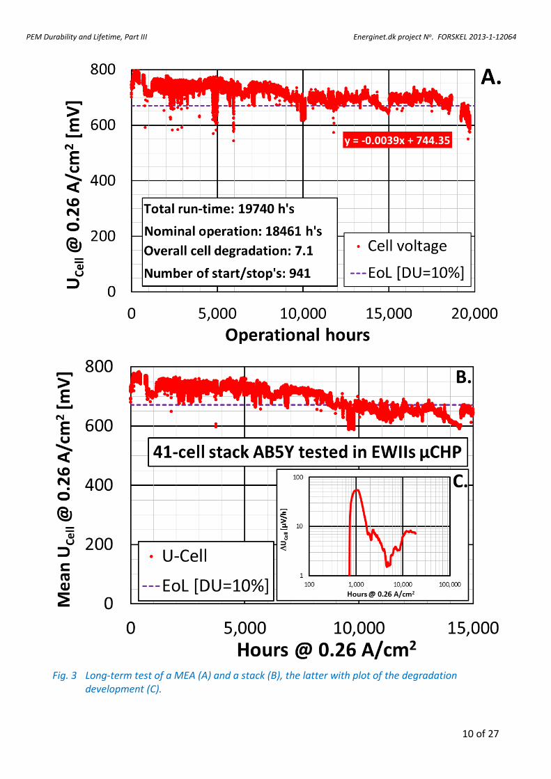
Fig. 3 Long-term test of a MEA (A) and a stack (B), the latter with plot of the degradation development (C).
PEM Durability and Lifetime, Part III Energinet.dk project No. FORSKEL 2013-1-12064
11 of 27
A.
B.
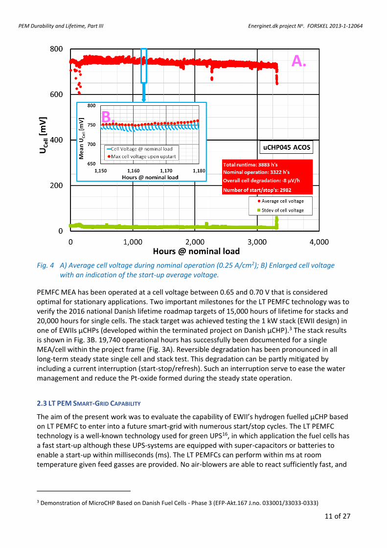
Fig. 4 A) Average cell voltage during nominal operation (0.25 A/cm2); B) Enlarged cell voltage with an indication of the start-up average voltage.
PEMFC MEA has been operated at a cell voltage between 0.65 and 0.70 V that is considered optimal for stationary applications. Two important milestones for the LT PEMFC technology was to verify the 2016 national Danish lifetime roadmap targets of 15,000 hours of lifetime for stacks and 20,000 hours for single cells. The stack target was achieved testing the 1 kW stack (EWII design) in one of EWIIs µCHPs (developed within the terminated project on Danish µCHP).3 The stack results is shown in Fig. 3B. 19,740 operational hours has successfully been documented for a single MEA/cell within the project frame (Fig. 3A). Reversible degradation has been pronounced in all long-term steady state single cell and stack test. This degradation can be partly mitigated by including a current interruption (start-stop/refresh). Such an interruption serve to ease the water management and reduce the Pt-oxide formed during the steady state operation.
2.3 LT PEM SMART-GRID CAPABILITY
The aim of the present work was to evaluate the capability of EWII’s hydrogen fuelled µCHP based on LT PEMFC to enter into a future smart-grid with numerous start/stop cycles. The LT PEMFC technology is a well-known technology used for green UPS16, in which application the fuel cells has a fast start-up although these UPS-systems are equipped with super-capacitors or batteries to enable a start-up within milliseconds (ms). The LT PEMFCs can perform within ms at room temperature given feed gasses are provided. No air-blowers are able to react sufficiently fast, and
3 Demonstration of MicroCHP Based on Danish Fuel Cells - Phase 3 (EFP-Akt.167 J.no. 033001/33033-0333)
PEM Durability and Lifetime, Part III Energinet.dk project No. FORSKEL 2013-1-12064
12 of 27
batteries or supercaps are therefore added to the system. The reported results are obtained as a joint effort in several projects. The experimental conditions are listed below:
Air circuit: Pressure: Ambient Quality: Outdoor air though a balanced vent
Stoichiometry: = 2.5 Humidity: 80% RH
H2(g) circuit: Pressure: 450±50 mbar Quality: +99.999%
Circuit: Dead-end
System stoichiometry: = <1.05 Cooling: Media: DI water Operational temperature: 63±3ºC Current Nominal operation 40 A corresponding to 0.25 A/cm2
The fuel cell was operated on a “1 hour On/1 hour Off scheme”. This allowed the fuel cell to cool
down to 35ºC between each cycle. The stack/µCHP has been exposed to almost 3,000 start/stop cycles (Fig. 4). The initial cell voltage is at a maximum upon start-up followed by a decline during ‘steady-state’ load (Fig. 4B). Recently, many research groups have paid attention to the system strategies of start-up and shut down operations to enhance the durability of PEMFCs. The published results are based on 80 to 1,500 start/stop cycles. The most significant results are published by Yu et al.17-18 Yu et al.17 have investigated two setups, one (1) where the cathode circuit was open to air in idle mode, and one (1) with a closed cathode (no oxygen) during idle mode. Yu et al. (up cit.) applied 1,500 start/stop cycles and measured a degradation rate, which they solely relate to the start/stop cycles. Yu et al. measured a degradation rate that was 2.5-4.5 times higher than recorded in the present study. It must therefore in this light be concluded that EWII has managed to prove that with an appropriate BoP and fuel circuit control the LT PEMFC technology has the possibility to operate within a future smart-grid scenario.
PEM Durability and Lifetime, Part III Energinet.dk project No. FORSKEL 2013-1-12064
13 of 27
3. COMPONENT RECOVERY AND EX-SITU TEST - SDU
The electrochemical removal of platinum directly from EoL LT PEMFC MEAs only resulted in 8% of the possible Pt-yield. This yield is far below the 80%s yield achieved for BoL MEA. The poor yield for EoL MEAs are likely a consequence of insufficient electrode‐electrolyte contact. The technique is furthermore time consuming as well as equipment intensive. For these reasons, the development of electrochemical removal of platinum directly from a EoL MEA discontinued after the first project year. The work has instead been concentrated to explore the possibilities of efficiently dissolving platinum from EoL fuel cell electrodes by application of a static potential and elevated temperature. In such a process, the platinum particles are expected to only abruptly have electrical contact to the electrodes. The results of the potentiostatic technique applied is summarised below.
All development conducted at SDU with respect to recovery of MEA components and especially PGMs has been in accordance with the outlines of the patent application. The patent has been granted in the United States and grants are currently pending in the EU and china. All work done in this project has been done in the framework of the patent.
The process involves the following three major operations:
Separation of MEA into GDL/catalyst layers and membrane. Catalyst adheres to both Gas Diffusion Layer, GDL, and membrane
Removal of catalyst/carbon particles from the surface of either GDL or membrane
Electrochemical dissolution and recovery of catalyst particles
The processes will be discussed in greater detail below
3.1 SEPARATION
The separation is done by immersion into an alcoholic solution. This facilitates easy separation and is not the limiting process with respect to automatisation.
The measurement of loading is reproducibly determined with X-ray Fluorescence (XRF), provided a good calibration has been done. XRF is a fast, contactless measurement technique. It allows for assessing catalyst loading both before and after separation of the MEA.
3.2 REMOVAL
The catalyst/carbon particles normally adhere to both membrane and GDL and need to be removed from both. The catalyst is removed from the GDL by scraping whereas the particles on the membrane are removed by dissolution of the membrane and subsequent isolation of the particles. The particles from the GDL and the membrane are merged into hydrochloric acid and is ready for the electrochemical dissolution. The dissolved membrane can be recovered and reused as ionomer in new MEAs although this has not been verified experimentally.
3.3 ELECTROCHEMICAL DISSOLUTION
The dissolution of platinum or in more general terms Precious Group Metals (PGMs) is achieved by applying a varying electrochemical potential in an electrochemical fluidized bed reactor (EFBR). The EFBR brings about the oxidation of the platinum (PGM) and in the presence of chloride ions the oxidized platinum complexes to yield a stable complex.19,20,21,22,23 The method as such is well
PEM Durability and Lifetime, Part III Energinet.dk project No. FORSKEL 2013-1-12064
14 of 27
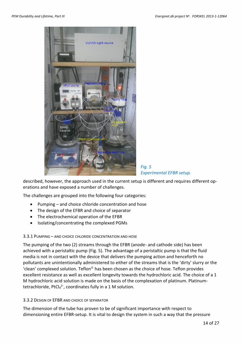
Fig. 5 Experimental EFBR setup.
described, however, the approach used in the current setup is different and requires different op-erations and have exposed a number of challenges.
The challenges are grouped into the following four categories:
Pumping – and choice chloride concentration and hose
The design of the EFBR and choice of separator
The electrochemical operation of the EFBR
Isolating/concentrating the complexed PGMs
3.3.1 PUMPING – AND CHOICE CHLORIDE CONCENTRATION AND HOSE
The pumping of the two (2) streams through the EFBR (anode- and cathode side) has been achieved with a peristaltic pump (Fig. 5). The advantage of a peristaltic pump is that the fluid media is not in contact with the device that delivers the pumping action and henceforth no pollutants are unintentionally administered to either of the streams that is the ‘dirty’ slurry or the
‘clean’ complexed solution. Teflon has been chosen as the choice of hose. Teflon provides excellent resistance as well as excellent longevity towards the hydrochloric acid. The choice of a 1 M hydrochloric acid solution is made on the basis of the complexation of platinum. Platinum-tetrachloride, PtCl42-, coordinates fully in a 1 M solution.
3.3.2 DESIGN OF EFBR AND CHOICE OF SEPARATOR
The dimension of the tube has proven to be of significant importance with respect to dimensioning entire EFBR-setup. It is vital to design the system in such a way that the pressure
PEM Durability and Lifetime, Part III Energinet.dk project No. FORSKEL 2013-1-12064
15 of 27
drop is well controlled and such that the slurry cannot accumulate in any part of the system. Unfortunately the laboratory equipment did not allow for a precise control of the pressure drop, which resulted in challenges with respect to flow of hydrochloric acid from cathode to anode and prevented efficient operation of the EFBR. The operation of the EFBR also requires careful selection of the membrane. The membrane has to be able to withstand low pH and provide passage of the complexed PGM without allowing passage of the carbon particles. Several membranes were tested, however, only one made of polyethylene qualified for operation in the EFBR.
3.3.3 THE ELECTROCHEMICAL OPERATION OF THE EFBR
The operation of the EFBR was controlled from the potentiostat, in this case a Zahner IM6ex. As a standalone system the software for the potentiostat (Thales software) works without problems. On a multithreaded system like windows, however, the potentiostat software fails to operate if a program with the same threading priority ‘steals’ time from the program. As a result the entire system only worked flawlessly if a second computer was operating everything but the software for the potentiostat. In most cases this was not a problem, however may present a problem if the operator is not aware of this.
It proved possible to selectively dissolve ruthenium before the platinum was dissolved. Thus, by carefully selecting the potential window it was possible to selectively dissolve ruthenium without dissolving platinum. This is very important since it opens up for a way to isolate the ruthenium from platinum only based on the potential window. Unfortunately, the challenges associated with pressure drop impeded the assessment of the recovery of the PGMs as well as establishing the current efficiency for the oxidation of platinum.
3.4.4 CONCENTRATING THE COMPLEXED PGMS
The concentration of PGMs is achieved by nanofiltration. The typical operating pressure range for the membrane is from 20–60 bar, which requires a pump capable of delivering this pressure. With respect to concentrating and further isolating the single compounds it has been established that for Pt(IV) as a single compound a concentration of in the range of 10-100 times is achieved.
3.5 CONCLUSION
It has been shown that platinum as well as ruthenium can be dissolved electrochemically in hydrochloric acid to produce the corresponding chloro-complexed ion. The electrochemical fluidised bed reactor has been constructed in a way that allows for the passage of the complexed ion from a ‘dirty’ hydrochloric acid slurry to a ‘clean’ hydrochloric acid solution. Unfortunately the amount of recovered platinum/ruthenium has not been established nor the current efficiency of the system. This is due to technical issues and not related to chemical restraints. As such the operation of the entire setup has shown that operating with laboratory equipment sometimes poses other unforeseen challenges compared to working in industrial scale. Some of the main issues have been to control the pressure drop of the entire system as well as achieving a stable performance of the potentiometer.
It has also been demonstrated that sequential dissolution of the PGM is possible. This in turn facilitates easier separation of mixtures of PGM into more clean fractions of PGM, however, this needs to be explored in greater detail. The concentration of the complexed PGM-ion can be achieved by nanofiltration, which yields approximately a 10 to 100-fold increase in concentration.
PEM Durability and Lifetime, Part III Energinet.dk project No. FORSKEL 2013-1-12064
16 of 27
4. HT-PEM
4.1 RESULTS AND WORK DONE AT DTU
Material durability tests at DTU are conducted with focus on both electrodes and membranes. Catalysts with different supporting materials are prepared based on which accelerated stress test protocols are evaluated for durability assessment. Durability tests have been commenced with focus on evaluating the long-term performance of thermally cross-linked membrane under mild operating conditions (cf. Table 5). At present, it has not been possible to establish a reproducible test protocol for measuring crossover currents under dry conditions, neither by means of chronoamperiometry nor by LCV. H2-crossover through the membrane was therefore be evaluated strictly from the OCV determined during polarisation curve sampling at BoL and EoT. Test procedures for measuring ECSA under dry conditions at BoL and EoT have been established. Suitable EIS parameters for measurement during continuous operation have been determined, providing a good signal-to-noise ratio while abiding by the linearity conditions prerequisite for such measurements.
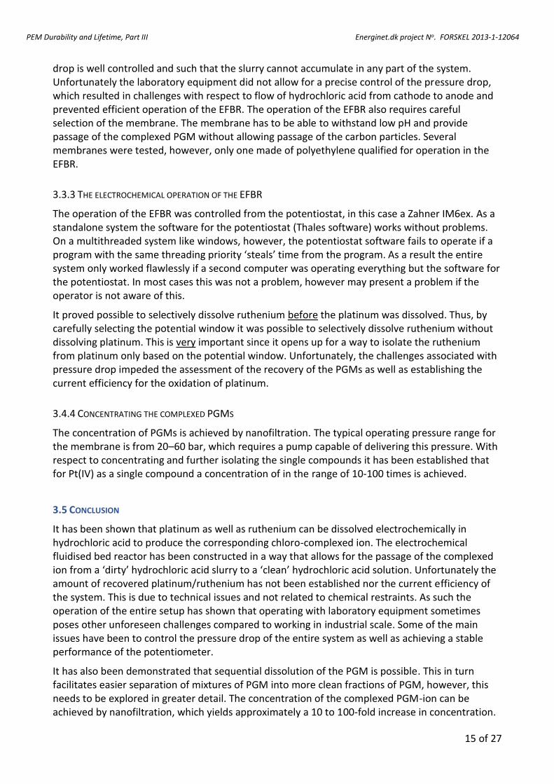
A study of the durability of MEAs based on standard PBI and MEAs based on cross-linked membranes has been done. The test matrix is shown in Table 5. In general, the lifetime curves are in reasonable agreement with the EIS spectra when evaluated with comparison to the polarisation resistance alone. The lifetime behaviour of the MEAs based on standard PBI during the first 4,700 h of operation can be roughly divided into an initial activation and a peak performance at around 1,000 hours, followed by a steady yet slow degradation (Fig. 6). The overall cell performance was about 20 mV lower for the MEAs based on cross-linked membrane, likely due to the slight differences in acid doping level. The long-term tested MEA based on the crosslinked membrane type (MEA-13-520) exhibits a very low degradation rate of only 0.5 µV/h, which is much lower than the other samples evaluated in this experiment, also lower than any report in literature, though the MEAs based on standard membranes have been slightly outperforming those based on crosslinked membranes so far.
Table 5 Test matrix for the comparison of standard MEAs versus cross-linked MEAs. Current density Galvanostatic control at 200 mA/cm2
Temperature Fixed temperature of 160°C
RH Ambient humidity (i.e. no control)
Gases H2/air (λH2/Air= 2/4)
Pressure Atmospheric
Individual sample test duration 0, 1000, 2000, 4000, 8000 hours
Sample name Test channel no Test duration [h]
0 1000 2000 4000 8000
MEA1 - X
MEA2 1 XXXXXXXXXXX
MEA3 XXXXXXXXXXXXXXXXX
MEA4 XXXXXXXXXXXXXXXXXXXXXXX
MEA5 2 XXXXXXXXXXXXXXXXXXXXXXXXXXX
CL_MEA1 - X
CL_MEA2 3 XXXXXXXXXXX
CL_MEA3 XXXXXXXXXXXXXXXXX
CL_MEA4 XXXXXXXXXXXXXXXXXXXXXXX
CL_MEA5 4 XXXXXXXXXXXXXXXXXXXXXXXXXXX
PEM Durability and Lifetime, Part III Energinet.dk project No. FORSKEL 2013-1-12064
17 of 27
Fig. 6 Lifetime curves of MEAs based on thermally cross-linked membranes compared to MEAs
based on the DPS standard PBI membranes. Signals from periodic EIS sampling and unexpected transitory disturbances in operation have been masked for visual clarification. Segmented linear fits from post break-in (1,000 h) to EoT have been superimposed onto the lifetime curves with corresponding degradation rates presented in the legend for the figure.
Fig. 7 Cross-sectional proton conductivity for the phosphoric acid doped membranes with (mPBI):(PWA-meso-SiO2) weight ratios ranging from 0-40 wt%. The conductivity data were calculated from the ohmic resistance extracted from the linear regions of fuel cell polarisation curves at high current density.
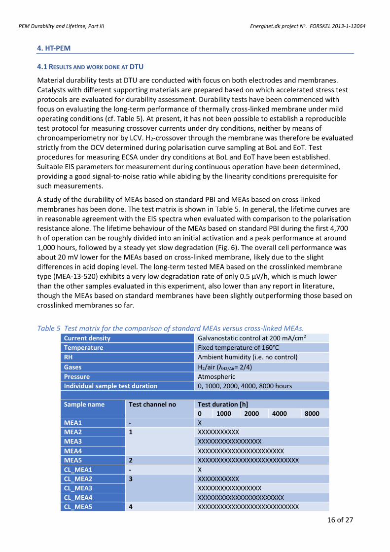
Significant progress has been made in evaluating composite electrolytes of mPBI and inorganic phosphotungstic acid filled mesoporous silica (mPBI: PWA-meso-SiO2). Improved dispersion of PWA-meso-SiO2 (40 wt% PWA) in mPBI has been attained by surface modification of the inorganic component using dequalinium chloride hydrate DCH. Composite materials of this type have been characterized with respect to fundamental physicochemical properties and evaluated as electrolytes in fuel cell tests. Compared to pristine mPBI, the in-situ proton conductivity was nearly unchanged for samples with a PWA-meso-SiO2 loading of 5-10 wt%. Further increase of the PWA-meso-SiO2 loading to 40 wt%, resulted in slightly lowered proton conductivity, as shown in Fig. 7.
PEM Durability and Lifetime, Part III Energinet.dk project No. FORSKEL 2013-1-12064
18 of 27
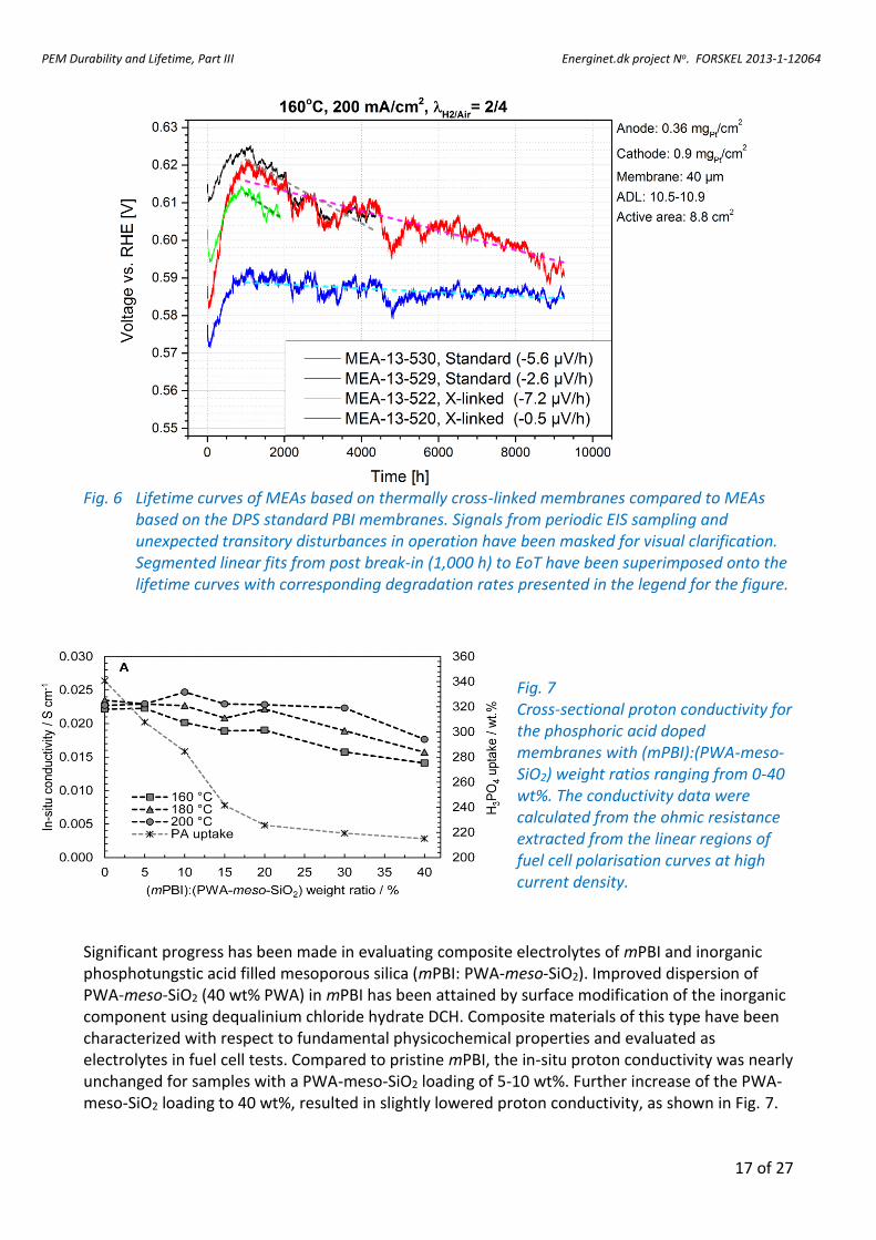
Fig. 8 A) Polarization curves for fuel cells based on the composites with PWA-meso-SiO2 loadings of 0, 5 and 15 wt%; B) Long-term stability tests of corresponding fuel cell operated at 200 mA cm-2 and 200°C; C) Variation of the in-situ membrane conductivity with time.
However, it should be noted that increasing the inorganic content from 0 to 40 wt% also resulted in a reduction of phosphoric acid uptake from 341 wt% to 215 wt% during the subsequent phosphoric acid doping. With phosphoric acid loss from the membrane being suspected as a major mode of degradation, membranes that are less dependent on high phosphoric acid contents are strongly desirable.
AST investigations incorporating elevated temperatures as the primary stressor have been performed. These investigations have concluded with key results showing improved durability of MEAs that are based on the type of composite membranes developed within this project (Fig. 8A-C). From the representative polarization curves (Fig. 8A), it can be seen that the characteristics of the MEAs are initially quite similar for the samples containing 0 and 5 wt% fillers. It is evident that the initial performance was comparably lower for the MEA with a 15 wt% loading of phosphotungstic acid filled mesoporous silica (PWA-meso-SiO2). This is also seen in Fig. 8B where the cell voltage at 200 mA cm-2 is plotted as a function of the testing time. With time of the durability test, the slope of the I-V curves becomes steeper for all three (3) MEAs, a clear indication that the conductivity of the cells decreases over the course of the durability test, as shown Fig. 8C. This degradation is significantly reduced with increasing content of PWA-meso-SiO2. It is very likely that incorporating this type of filler into the membrane leaves the MEA more tolerant towards high temperature operation because the composite MEAs are less influenced by phosphoric acid leaching and membrane dehydration.
As seen from Fig. 8A, the membrane with high filler content (15 wt%) exhibits a slightly lower
PEM Durability and Lifetime, Part III Energinet.dk project No. FORSKEL 2013-1-12064
19 of 27
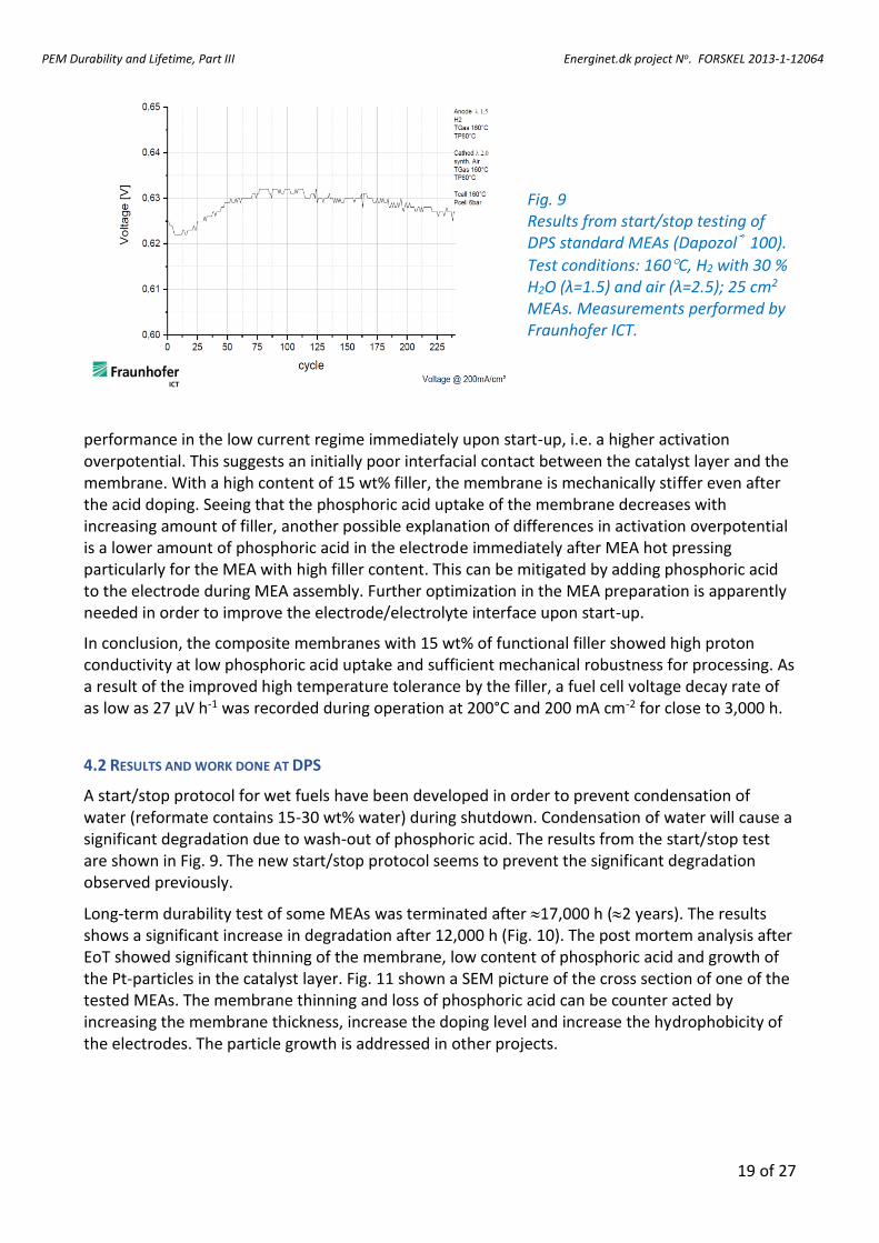
Fig. 9 Results from start/stop testing of DPS standard MEAs (Dapozol® 100).
Test conditions: 160C, H2 with 30 % H2O (λ=1.5) and air (λ=2.5); 25 cm2 MEAs. Measurements performed by Fraunhofer ICT.
performance in the low current regime immediately upon start-up, i.e. a higher activation overpotential. This suggests an initially poor interfacial contact between the catalyst layer and the membrane. With a high content of 15 wt% filler, the membrane is mechanically stiffer even after the acid doping. Seeing that the phosphoric acid uptake of the membrane decreases with increasing amount of filler, another possible explanation of differences in activation overpotential is a lower amount of phosphoric acid in the electrode immediately after MEA hot pressing particularly for the MEA with high filler content. This can be mitigated by adding phosphoric acid to the electrode during MEA assembly. Further optimization in the MEA preparation is apparently needed in order to improve the electrode/electrolyte interface upon start-up.
In conclusion, the composite membranes with 15 wt% of functional filler showed high proton conductivity at low phosphoric acid uptake and sufficient mechanical robustness for processing. As a result of the improved high temperature tolerance by the filler, a fuel cell voltage decay rate of as low as 27 μV h-1 was recorded during operation at 200°C and 200 mA cm-2 for close to 3,000 h.
4.2 RESULTS AND WORK DONE AT DPS
A start/stop protocol for wet fuels have been developed in order to prevent condensation of water (reformate contains 15-30 wt% water) during shutdown. Condensation of water will cause a significant degradation due to wash-out of phosphoric acid. The results from the start/stop test are shown in Fig. 9. The new start/stop protocol seems to prevent the significant degradation observed previously.
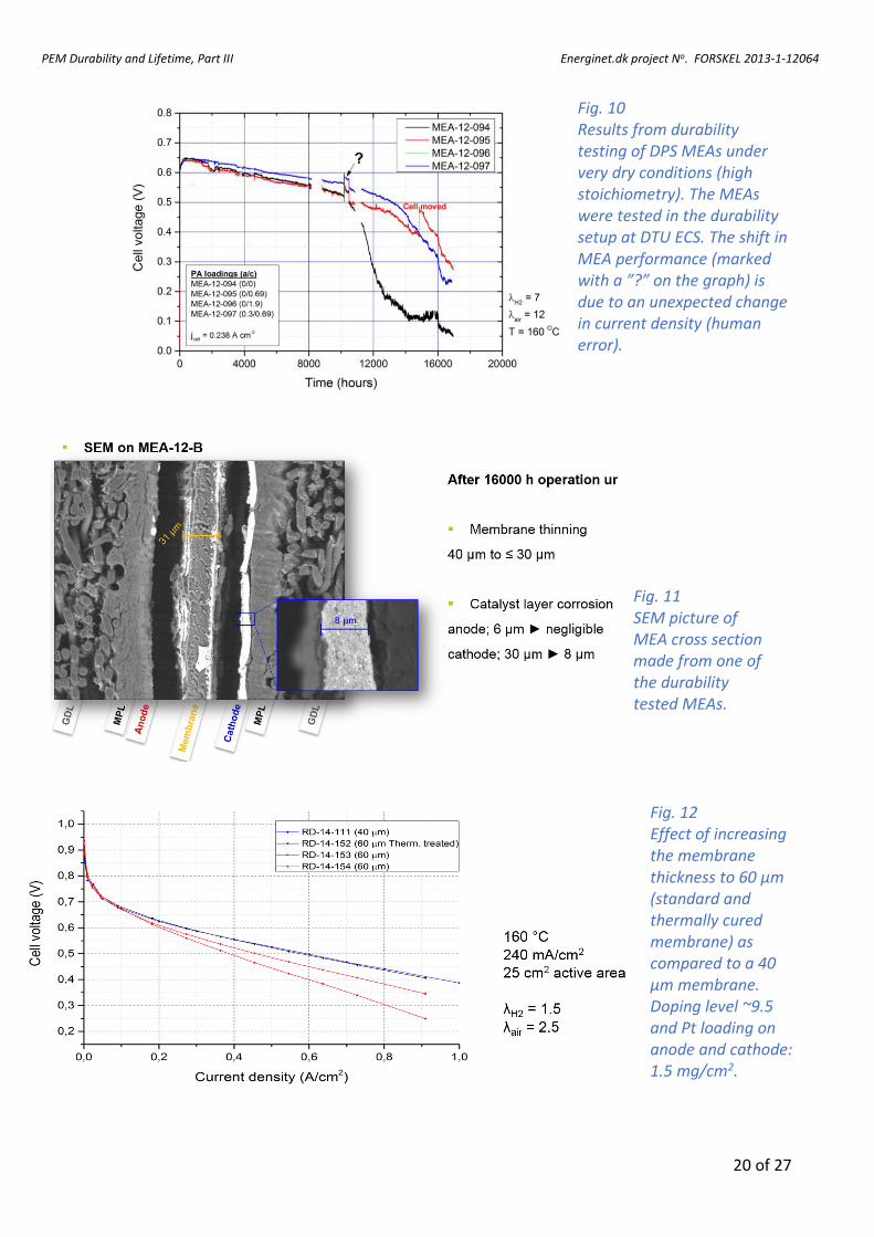
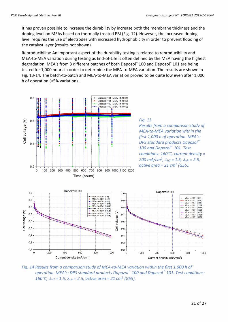
Long-term durability test of some MEAs was terminated after 17,000 h (2 years). The results shows a significant increase in degradation after 12,000 h (Fig. 10). The post mortem analysis after EoT showed significant thinning of the membrane, low content of phosphoric acid and growth of the Pt-particles in the catalyst layer. Fig. 11 shown a SEM picture of the cross section of one of the tested MEAs. The membrane thinning and loss of phosphoric acid can be counter acted by increasing the membrane thickness, increase the doping level and increase the hydrophobicity of the electrodes. The particle growth is addressed in other projects.
PEM Durability and Lifetime, Part III Energinet.dk project No. FORSKEL 2013-1-12064
20 of 27
Fig. 10 Results from durability testing of DPS MEAs under very dry conditions (high stoichiometry). The MEAs were tested in the durability setup at DTU ECS. The shift in MEA performance (marked with a ”?” on the graph) is due to an unexpected change in current density (human error).
Fig. 11 SEM picture of MEA cross section made from one of the durability tested MEAs.
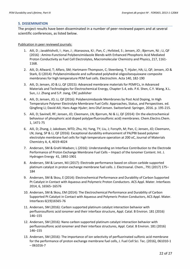
Fig. 12 Effect of increasing the membrane thickness to 60 µm (standard and thermally cured membrane) as compared to a 40 µm membrane. Doping level ~9.5 and Pt loading on anode and cathode: 1.5 mg/cm2.
PEM Durability and Lifetime, Part III Energinet.dk project No. FORSKEL 2013-1-12064
21 of 27
It has proven possible to increase the durability by increase both the membrane thickness and the doping level on MEAs based on thermally treated PBI (Fig. 12). However, the increased doping level requires the use of electrodes with increased hydrophobicity in order to prevent flooding of the catalyst layer (results not shown).
Reproducibility: An important aspect of the durability testing is related to reproducibility and MEA-to-MEA variation during testing as End-of-Life is often defined by the MEA having the highest degradation. MEA’s from 3 different batches of both Dapozol® 100 and Dapozol® 101 are being tested for 1,000 hours in order to determine the MEA-to-MEA variation. The results are shown in Fig. 13-14. The batch-to-batch and MEA-to-MEA variation proved to be quite low even after 1,000 h of operation (<5% variation).
Fig. 13 Results from a comparison study of MEA-to-MEA variation within the first 1,000 h of operation. MEA’s: DPS standard products Dapozol® 100 and Dapozol® 101. Test
conditions: 160C, current density =
200 mA/cm2, H2 = 1.5, air = 2.5, active area = 21 cm2 (G55).
Fig. 14 Results from a comparison study of MEA-to-MEA variation within the first 1,000 h of operation. MEA’s: DPS standard products Dapozol® 100 and Dapozol® 101. Test conditions:
160C, H2 = 1.5, air = 2.5, active area = 21 cm2 (G55).
PEM Durability and Lifetime, Part III Energinet.dk project No. FORSKEL 2013-1-12064
22 of 27
5. DISSEMINATION
The project results have been disseminated in a number of peer-reviewed papers and at several scientific conferences, as listed below.
Publication in peer reviewed journals:
1. Aili, D ; Javakhishvili, I ; Han, J ; Atanasova, KJ ; Pan, C ; Hvilsted, S ; Jensen, JO ; Bjerrum, NJ ; Li, QF (2016) : Amino-Functional Polybenzimidazole Blends with Enhanced Phosphoric Acid Mediated Proton Conductivity as Fuel Cell Electrolytes, Macromolecular Chemistry and Physics, 217, 1161-1168.
2. Aili, D; Allward, T; Alfaro, SM; Hartmann-Thompson, C; Steenberg, T; Hjuler, HA; Li, QF; Jensen, JO & Stark, EJ (2014): Polybenzimidazole and sulfonated polyhedral oligosilsesquioxane composite membranes for high temperature PEM fuel cells. Electrochim. Acta 140, 182-190
3. Aili, D; Jensen, JO & Li, QF (2015): Advanced membrane materials for PEMFCs, in Advanced Materials and Technologies for Electrochemical Energy, Chapter 5.4, eds. P.K. Shen, C.Y. Wang, X.L. Sun, J.J. Zhang and S.P. Jiang, CRC publisher
4. Aili, D; Jensen, JO; Li, QF (2016): Polybenzimidazole Membranes by Post Acid Doping, In High Temperature Polymer Electrolyte Membrane Fuel Cells: Approaches, Status, and Perspectives. ed. Qingfeng Li; David Aili; Hans Aage Hjuler; Jens Oluf Jensen. Switzerland: Springer, 2016. p. 195-215.
5. Aili, D; Savinell, RF; Jensen, JO; Cleemann, LN; Bjerrum, NJ & Li, QF (2014): On the electrochemical behaviour of phosphoric acid doped poly(perfluorosulfonic acid) membranes. Chem.Electro.Chem. 1, 1471-75
6. Aili, D; Zhang, J; Jakobsen, MTD; Zhu, HJ; Yang, TY; Liu, J; Forsyth, M; Pan, C; Jensen, JO; Cleemann, LN; Jiang, SP & Li, QF (2016): Exceptional durability enhancement of PA/PBI based polymer electrolyte membrane fuel cells for high temperature operation at 200 oC, Journal of Materials Chemistry A, 4, 4019-4024
7. Andersen, SM & Grahl-Madsen; L (2016): Understanding on Interface Contribution to the Electrode Performance of Proton Exchange Membrane Fuel Cells – Impact of the Ionomer Content. Int. J. Hydrogen Energy 41, 1892-1901
8. Andersen, SM & Larsen, MJ (2017): Electrode performance based on silicon carbide supported platinum catalyst in proton exchange membrane fuel cells. J. Electroanal. Chem., 791 (2017) 175–184
9. Andersen, SM & Skou, E (2014): Electrochemical Performance and Durability of Carbon Supported Pt Catalyst in Contact with Aqueous and Polymeric Proton Conductors. ACS Appl. Mater. Interfaces 2014, 6, 16565−16576
10. Andersen, SM & Skou, EM (2014): The Electrochemical Performance and Durability of Carbon Supported Pt Catalyst in Contact with Aqueous and Polymeric Proton Conductors, ACS Appl. Mater. Interfaces 6(19)16565-76
11. Andersen, SM (2016): Carbon supported platinum catalyst interaction behavior with perfluorosulfonic acid ionomer and their interface structure, Appl. Catal. B Environ. 181 (2016) 146–155
12. Andersen, SM (2016): Nano carbon supported platinum catalyst interaction behavior with perfluorosulfonic acid ionomer and their interface structures, Appl. Catal. B Environ. 181 (2016) 146–155
13. Andersen, SM (2016): The importance of ion selectivity of perfluorinated sulfonic acid membrane for the performance of proton exchange membrane fuel cells, J. Fuel Cell Sci. Tec. (2016), 061010-1 – 061016-7
PEM Durability and Lifetime, Part III Energinet.dk project No. FORSKEL 2013-1-12064
23 of 27
14. Andersen, SM (2016): The importance of ion selectivity of perfluorinated sulfonic acid membrane for the performance of proton exchange membrane fuel cells, J. Fuel Cell Sci. Tec. (2016), 061010-1 – 061016-7
15. Andersen, SM; Borghei, M, Dhiman, R; Jiang, H; Ruiz, V, Kauppinen, E & Skou, E (2014): Interaction of multi-walled carbon nanotubes with perfluorinated sulfonic acid ionomers and surface treatment studies. j.carbon.2014.01.032
16. Andersen, SM; Borghei, M; Dhiman, R; Ruiz, V; Kauppinen, E & Skou, E (2014): Adsorption behavior of Perfluorinted sulfonic acid ionomer on highly graphitised carbon nanofibers and their thermal stabilities. J. Phys. Chem.C 2014, 118, 10814-823.
17. Andersen, SM; Borghei, M; Dhiman, R; Ruiz, V; Kauppinen, E & Skou, EM (2014): Adsorption behavior of perfluorinated sulfonic acid ionomer on highly graphitized carbon nanofibers and their thermal stabilities, ACS J. Phys. Chem. C 118, 10814-23
18. Andersen, SM; Dhiman, R & Skou, E (2015): Chemistry of carbon polymer composite electrode - An X-ray photoelectron spectroscopy study. Journal of Power Sources 274 (2015) 1217-23
19. Andersen, SM; Dhiman, R & Skou, E (2015): X-ray Photoelectron Spectroscopy Investigation on Electrochemical Degradation of Proton Exchange Membrane Fuel Cell Electrodes, J. Power Sources, 282 (2015) 87-94.
20. Andersen, SM; Dhiman, R, Larsen, MJ & Skou, E (2015), Importance of Electrode Hot-Pressing Conditions for the Catalyst Performance of Proton Exchange Membrane Fuel Cells, Appl. Cata. B 172 (2015) 82-90
21. Andersen, SM; Nørgaard, CF; Larsen; MJ & Skou, E (2015): Tin Dioxide as an Effective Antioxidant for Proton Exchange Membrane Fuel Cells. Journal of Power Sources 273 (2015) 158-161
22. Cleemann, LN; Buazar; F; Li; QF; Jensen, JO; Pan, C; Steenberg, T; Liu, CD; Dai, S & Bjerrum, NJ (2013): Catalyst Degradation in High Temperature Proton Exchange Membrane Fuel Cells Based on Acid Doped Polybenzimidazole Membranes. Fuel Cells 13, 822-31
23. Hussainova, I; Ivanov, R; Stamatin, SN; Anoshkin, IV; Skou, E & Nasibulin, AB (2015): A few-layered graphene on alumina nanofibers for electrochemical energy conversion, Carbon 88 (2015)157–164
24. Jakobsen, MTD; Jensen, JO; Cleemann, LN & Li, QF (2015): Durability Issues and Status of PBI Based Fuel Cells (Chap. 22), in High Temperature Polymer Electrolyte Membrane Fuel Cells - Approaches, Status and Perspective, ed. Q. Li, D Aili, H. A. Hjuler, J. O. Jensen, ISBN 978-3-319-17081-7, DOI 10.1007/978-3-319-17082-4, Springer
25. Li, QF; Aili, D; Savinell, RF; Jensen, JO (2016): Acid–Base Chemistry and Proton Conductivity, in High Temperature Polymer Electrolyte Membrane Fuel Cells: Approaches, Status, and Perspectives. ed. Qingfeng Li; David Aili; Hans Aage Hjuler; Jens Oluf Jensen. Switzerland : Springer, 2016. p. 37-57.
26. Liao, JH; Yang, JH; Li; QF; Cleemann, LN; Jensen, JO; Bjerrum, NJ; He, RE & Xing, W (2013): Oxidative degradation of acid doped polybenzimidazole membranes and fuel cell durability in the presence of ferrous ions. J. Power Sources 238, 516-22
27. Nguyen, V; Ziolo, N; Yang, Y; Diercks D; Alfaro S; Hjuler, HA; Steenberg, T; Herring AM (2017): Imbibed Polybenzimidazole for Enhanced Protonic Conductivity for High Temperature Fuel Cell Applications, J.Electrochem. Soc, accepted.
28. Nørgaard, CF; Stamatin, SN & Skou, EM (2014): Redeposition of electrochemically dissolved platinum as nanoparticles on carbon. Int. J. Hydrogen Energy 39(30)17322-26
29. Poulsen, MG; Larsen, MJ & Andersen, SM (2017): Improved Durability of Proton Exchange Membrane Fuel Cells by Introducing Sn (IV) Oxide into Electrodes using an Ion Exchange Method, J. Power Sources, 343 (2017) 174-182
PEM Durability and Lifetime, Part III Energinet.dk project No. FORSKEL 2013-1-12064
24 of 27
30. Søndergaard, T; Cleemann, LN; Becker, H; Aili, D; Steenberg, T; Hjuler, HA; Seerup, L; Li, QF, Jensen JO (2017) : Long-term durability of HT-PEM fuel cells based on thermally crosslinked polybenzimidazole. Journal of Power Sources, 342, 570-578.
31. Søndergaard, T; Cleemann, LN; Becker, H; Steenberg, T; Hjuler, HA; Seerup, L; Li, QF, Jensen JO (2017) : Parametric Accelerated Stress Test Study in Relation to Long-term Durability of PBI-based HT-PEM Fuel Cells, to be submitted to the Journal of the Electrochemical Society
32. Søndergaard, T; Cleemann, LN; Zhong, LJ ; Becker, H; Steenberg, T; Hjuler, HA; Seerup, L; Li, QF, Jensen JO (2017) : Catalyst Degradation Under Potential Cycling as an Accelerated Stress Test for PBI Based High Temperature PEM Fuel Cells - Effect of Humidification, to be submitted to Electrocatalysis.
33. Stamatin, SN; Borghei, M; Andersen, SM; Veltze, S; Ruiz, V; Kauppinen, E & Skou, E (2014): Influence of different carbon nanostructures on the electrocatalytic activity and stability of Pt supported electrocatalysts. I.J.Hydrogen Energy 39(2014)8215-24.
34. Stamatin, SN; Borghei, M; Dhiman, R; Andersen, SM; Ruiz, V; Kauppinen, E & Skou, E (2015): Activity and stability studies of platinizes multi-walled carbon nanotubes as fuel cell catalysts. Applied catalysis B: Environmental 162(2015)289-299
35. Stamatin, SN; Speder, J; Dhiman, R; Arenz, M and Skou, E (2015): Electrochemical Stability and Postmortem Studies of Pt/SiC Catalysts for Polymer Electrolyte Membrane Fuel Cells, ACS Appl. Mater. Interfaces 7 (2015) 6153−6161
36. Steenberg, T; Hjuler, HA; Terkelsen, C; Jensen, JO & Li, Q (2014): Membrane electrode assembly development for HT-PEM fuel cells. Proceedings of 20th World Hydrogen Energy Conference (WHEC 2014), 15-20 June 2014, Gwangju, South Korea (2014), ISBN: 9781634396554.
37. Yang, JS; Cleemann, LN; Steenberg, T; Terkelsen, C; Li, QF; Jensen, JO; Hjuler, HA; Bjerrum, NJ & He, RH (2014): High Molecular Weight Polybenzimidazole Membranes for High Temperature PEMFC. Fuel Cells, 14(1)7-15
38. Yuan, S; Guo, XX; Aili, D; Pan, C; Li, QF & Fang, JH (2014): Poly(imide benzimidazole)s for high temperature polymer electrolyte membrane fuel cells. J. Membr. Science 454, 351-58
Contribution to scientific text books:
1. Aili, D; Jensen, JO & Li, QF (2015): Advanced membrane materials for PEMFCs, in Advanced Materials and Technologies for Electrochemical Energy, Chapter 5.4, eds. P.K. Shen, C.Y. Wang, X.L. Sun, J.J. Zhang and S.P. Jiang, CRC publisher
2. Aili, D; Jensen, JO & Li, QF (2015): Polymers for Fuel Cells, in Encyclopedia of Polymeric Nanomaterials, eds. Shiro Kobayashi and Klaus Müllen, Essay 382482, ISBN 978-3-642-29647-5, in two volumes, Springer
Conferences:
1. Jakobsen, MTD; Jensen, JO; Cleemann LN; Li QF (2016), Durability Issues and Status of HT-PEM Based on Acid Doped Polybenzimidazoles, Invited talk at Symposium of CISTEM in association with Hydrogen Days 2016, April 6-8 2016, Prague, Czech Republic
2. Li QF; Aili, D; Jensen JO; Savinell, RF; Cleemann, LN; Bjerrum NJ (2014): Malfunction of Acid Doped Poly(perfluorosulfonic acid) Membranes in Fuel Cells – What Can We Learn from It? Invited talk, 17th Solid State Protonic Conductors, September 14-19, 2014, Seoul, Korea
3. Li, QF (2015): HT-PEM in Denmark: Durability Issues and Recent Progress of PBI Cells, Invited talk at Wuhan University of Science and Technology, 09. May 2015
PEM Durability and Lifetime, Part III Energinet.dk project No. FORSKEL 2013-1-12064
25 of 27
4. Li, QF; Aili, D; Cleemann LN; Jensen JO (2015): Acid-base Chemistry and Proton Conductivity of High Temperature Polymer Electrolytes, Invited talk at International Conference on Innovative Electrochemical Energy Materials and Technologies (EEMT2015) Nanning, China November 8-11, 2015
5. Li, QF; Aili, D; Jensen, JO; Savinell, RF; Cleemann LN; Bjerrum, NJ (2013): Acid Doped Polymer Membranes as an Approach to High Temperature Proton Exchange Membrane Fuel Cells: Successes and Peculiarities (Keynote speech), the 64th International Society of Electrochemistry, 8-12 Sept. 2013, Queretaro, Mexico
6. Li, QF; Jensen JO; Cleemann LN (2014): High Temperature PBI based PEMFC – Status, Challenges and Recent Progress (Keynote talk), International Conference on Electrochemical Energy Science and Technology, Donghua University, Shanghai, China, Oct. 21-Nov 4, 2014.
7. Li, QF; Jensen, JO; Martin, S; Aili, D & Cleemann, LN (2015): High Temperature Durable Membranes for Fuel Cells, invited talk at Advances in Polymers for Fuel Cells and Energy Devices, February 8-11, 2015, Asilomar Conference Grounds, Pacific Grove, California USA
Patent:
1. “Method for recovering platinum group metals from catalytic structures”. Applicant: SDU, Representative: Orsnes Patent, Inventors: E. M. Skou, C.F. Nørgaard, S. N. Stamatin. WO 2014166494A1 & US 9580826B
PEM Durability and Lifetime, Part III Energinet.dk project No. FORSKEL 2013-1-12064
26 of 27
6. REFERENCES
1 OZ Sharaf & MF Orhan (2014): An overview of fuel cell technology: Fundamentals and applications. Renewable and Sustainable Energy Reviews 32 (2014) 810–853
2 de Bruijn, FA; Dam, VAT & Janssen, GJM (2007): Review: Durability and Degradation Issues of PEM Fuel Cell Components. FUEL CELLS 08(1)3–22
3 Wu J, Yuan XZ, Martin JJ, Wang H, Zhang J, Shen J, et al. (2008): A review of PEM fuel cell durability: degradation mechanisms and mitigation strategies. J Power Sources 184(1)104–19
4 Schmidt TJ, Baurmeister J. J Power Sources 2008, 176: 428-434
5 Hartnig C, Schmidt TJ (2011), J Power Sources 196:5564-5572
6 Grot, S & Grot, W (2005): VII.E.1 Platinum Recycling Technology Development. DOE Hydrogen Program (http://www.hydrogen.energy.gov/pdfs/progress05/vii_e_1_grot.pdf )
7 Shore, L et al. (2005): Process for recycling components of a PEM Fuel Cell membrane electrode assembly. WIPO application ID: US11/110,406
8 Schmidt TJ, Baurmeister J (2006), ECS Transactions 3:861-869
9 Wannek C, Kohnen B, Oetien HF et al (2008), Fuel Cells 8:87-95
10 Yang J, Li Q, Cleemann LN et al (2012), J Mater Chem 22:11185-11195
11 Aili D, Cleemann LN, Li Q et al (2012), J Mater Chem 22:5444-5453
12 Galbiati S, Baricci A, Casalegno A et al (2013), Inter J Hydrogen Energy 38:6469-6480
13 Oono Y, Sounai A, Hori M (2012), J Power Sources 210:366-373
14 Oono Y, Sounai A, Hori M (2013), J Power Sources 241:87-93
15 Janßen H, Supra J, Lüke L et al (2013), Inter J Hydrogen Energy 38: 4705–4713
16 Sharaf, OZ & Orhan, MF (2014): An overview of fuel cell technology: Fundamentals and applications. Renewable and Sustainable Energy Reviews 32(2014)810–853
17 Yu, Y; Tu, Z; Zhang, H; Zhang, Z & Pan, M (2011): Comparison of degradation behaviors for open-ended and closed proton exchange membrane fuel cells during startup and shutdown cycles. J Power Sources 196(2011)5077-83
18 Yu, Y; Li, H; Wang, H; Yuan, Z-X; Wang, G & Pan, M (2012): A review on performance degradation of proton exchange membrane fuel cells during startup and shutdown processes: Causes, consequences, and mitigation strategies. J Power Sources 205 (2012)10–23
19 R. Latsuzbaia, E. Negro, G. J. M. Koper, “Environmentally Friendly Carbon-Preserving Recovery of Noble Metals From Supported Fuel Cell Catalysts”, ChemSusChem 2015, 8, 1926 – 1934
20 J. Speder, “Effect of potential cycling on platinum electrocatalysts in the presence of chloride anions”, Ph.d. thesis, University of Southern Denmark, 2010
21 G. Benke, W. Gnot, “The electrochemical dissolution of platinum”, Hydrometallurgy, Vol 64, 3, 2002, 205–218
22 S. Mitsushima, et al., “Dissolution of platinum in acidic media”, E. Acta, Vol 54, 2, 2008, 455–460
23 J. C. Meier, et al., “Degradation Mechanisms of Pt/C Fuel Cell Catalysts under Simulated Start−Stop Conditons,” ACS Catal., vol. 2, 832–843, 2012
PEM Durability and Lifetime, Part III Energinet.dk project No. FORSKEL 2013-1-12064
27 of 27
7. ABBREVIATIONS
AST Accelerated Stress Test BoL Beginning-of-Life BoP Balance-of-Plant CHP Combined Heat and Power DOE USA Department of Energy ECSA Electrochemical Surface Area EFBR Electrochemical Fluidized Bed Reactor EIS Electrochemical Impedance Spectroscopy EoL End-of-Life EoT End-of-Test FC Fuel Cell GDL Gas Diffusion Layer HT High Temperature LT Low Temperature M Project month e.g. M9 Project month 9 MEA Membrane Electrode Assemblies ms miliseconds MS MileStone e.g. MS1.2 meaning milestone no.2 in WP1 OCV Open Cell Voltage PBI Polybenzimidazole PEM Proton Exchangeable Membrane PFSA Perfluorosulfonic Acid PGM Precious Group Metals PTFE Polytetrafluoroethylene (Teflon) PWA Phosphotungstic acid SoA State-of-the-Art WP Work Package