Embed Size (px)
Citation preview
Fluid Mechanics
Chapter 6 Momentum Equation
Dr. Amer Khalil Ababneh
Introduction
The analysis of forces on vanes and pipe bends, the
thrust produced by a rocket or turbojet, and torque
produced by a hydraulic turbine are all examples of
the application of the momentum equation.
In this chapter the Reynolds transport theorem is applied
to Newton's second law of motion, F = ma, to develop
the Eulerian form of the momentum equation.
Application of this equation allows the engineer to
analyze forces and moments produced by flowing
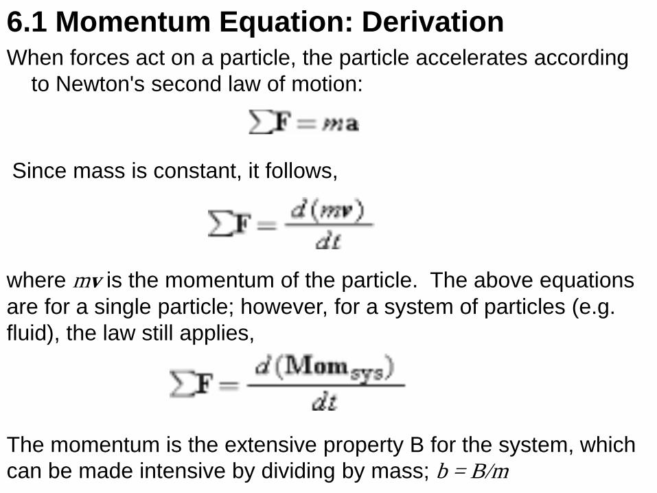
6.1 Momentum Equation: Derivation When forces act on a particle, the particle accelerates according
to Newton's second law of motion:
Since mass is constant, it follows,
where mv is the momentum of the particle. The above equations
are for a single particle; however, for a system of particles (e.g.
fluid), the law still applies,
The momentum is the extensive property B for the system, which
can be made intensive by dividing by mass; b = B/m
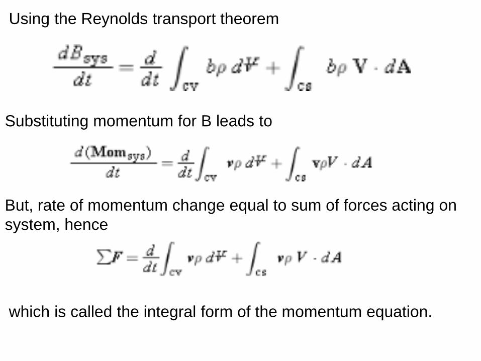
Using the Reynolds transport theorem
Substituting momentum for B leads to
But, rate of momentum change equal to sum of forces acting on
system, hence
which is called the integral form of the momentum equation.
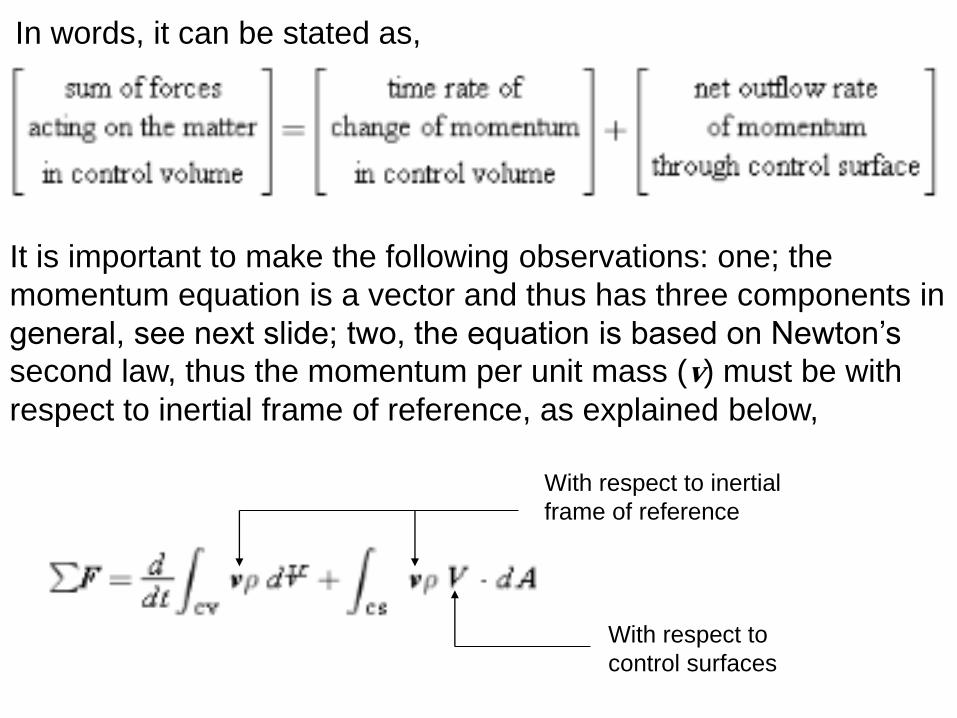
In words, it can be stated as,
It is important to make the following observations: one; the
momentum equation is a vector and thus has three components in
general, see next slide; two, the equation is based on Newton’s
second law, thus the momentum per unit mass (v) must be with
respect to inertial frame of reference, as explained below,
With respect to inertial
frame of reference
With respect to
control surfaces
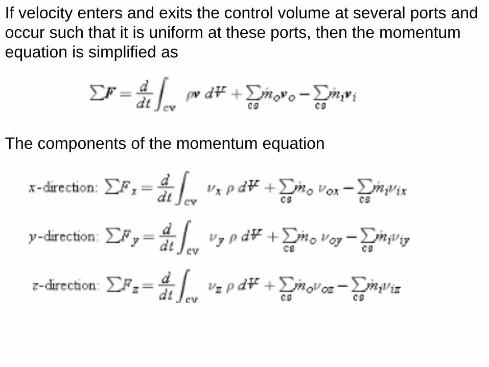
The components of the momentum equation
If velocity enters and exits the control volume at several ports and
occur such that it is uniform at these ports, then the momentum
equation is simplified as
In applying the momentum equation follow these steps:
1) identify and draw the control volume
2) draw the coordinate system
3) identify where mass enters/leaves the control volume
4) identify the forces acting on the control volume
For forces there two kinds: 1) is called body forces like gravity
which acts at every element of the body; 2) surface forces,
which require a contact with the control volume, thus they act at
the surfaces of the control volume.
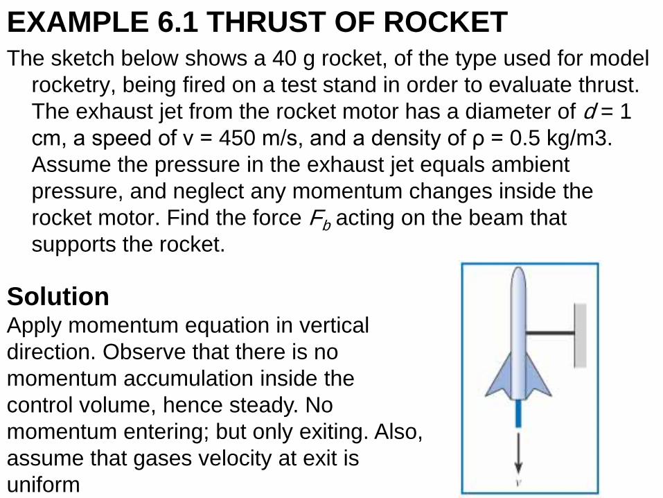
EXAMPLE 6.1 THRUST OF ROCKET The sketch below shows a 40 g rocket, of the type used for model
rocketry, being fired on a test stand in order to evaluate thrust.
The exhaust jet from the rocket motor has a diameter of d = 1
cm, a speed of ν = 450 m/s, and a density of ρ = 0.5 kg/m3.
Assume the pressure in the exhaust jet equals ambient
pressure, and neglect any momentum changes inside the
rocket motor. Find the force Fb acting on the beam that
supports the rocket.
Solution Apply momentum equation in vertical
direction. Observe that there is no
momentum accumulation inside the
control volume, hence steady. No
momentum entering; but only exiting. Also,
assume that gases velocity at exit is
uniform
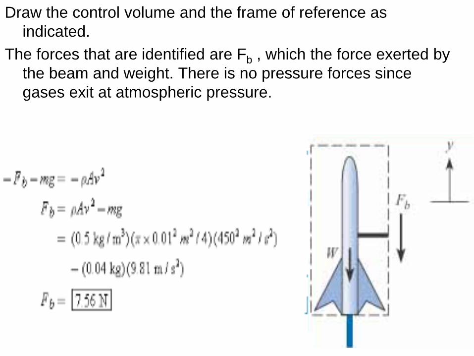
Draw the control volume and the frame of reference as
indicated.
The forces that are identified are Fb , which the force exerted by
the beam and weight. There is no pressure forces since
gases exit at atmospheric pressure.
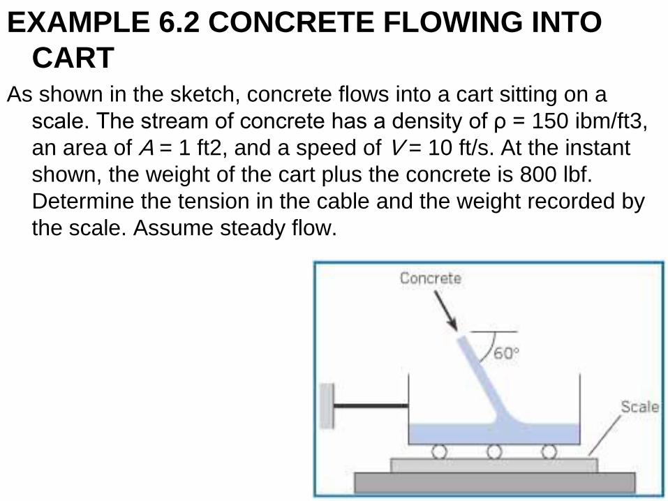
EXAMPLE 6.2 CONCRETE FLOWING INTO
CART As shown in the sketch, concrete flows into a cart sitting on a
scale. The stream of concrete has a density of ρ = 150 ibm/ft3,
an area of A = 1 ft2, and a speed of V = 10 ft/s. At the instant
shown, the weight of the cart plus the concrete is 800 lbf.
Determine the tension in the cable and the weight recorded by
the scale. Assume steady flow.
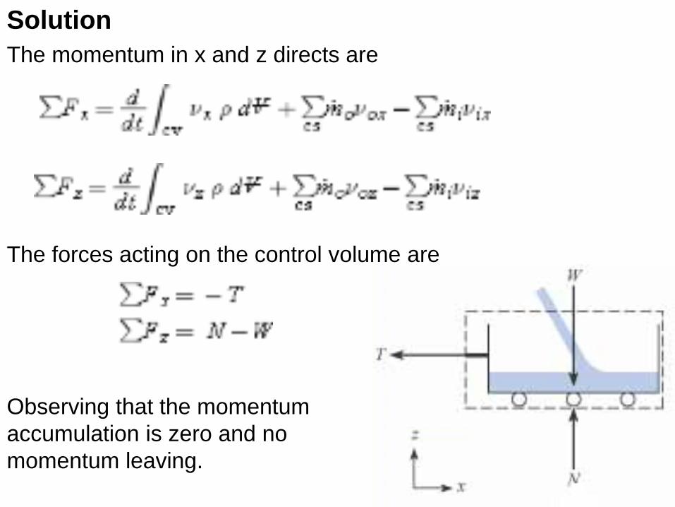
Solution
The momentum in x and z directs are
The forces acting on the control volume are
Observing that the momentum
accumulation is zero and no
momentum leaving.
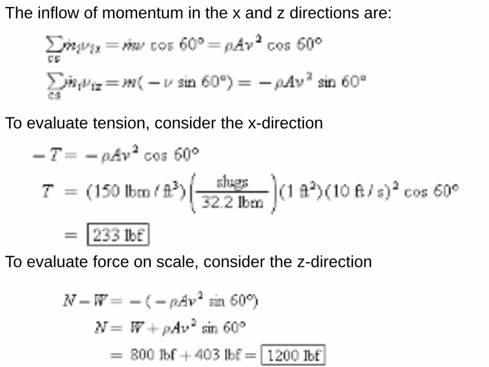
The inflow of momentum in the x and z directions are:
To evaluate tension, consider the x-direction
To evaluate force on scale, consider the z-direction
Nozzles Nozzles are flow devices used to accelerate a fluid stream by
reducing the cross-sectional area of the flow. When a fluid flows
through a nozzle, it is reasonable to assume the velocity is
uniform across inlet and outlet sections. Hence,the momentum
flows will have magnitude If the nozzle exhausts into the
atmosphere, the pressure at the exit is atmospheric.
In many applications involving finding the force on a nozzle, the
Bernoulli equation is used along with the momentum equation.
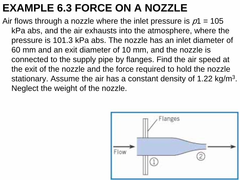
EXAMPLE 6.3 FORCE ON A NOZZLE Air flows through a nozzle where the inlet pressure is p1 = 105
kPa abs, and the air exhausts into the atmosphere, where the
pressure is 101.3 kPa abs. The nozzle has an inlet diameter of
60 mm and an exit diameter of 10 mm, and the nozzle is
connected to the supply pipe by flanges. Find the air speed at
the exit of the nozzle and the force required to hold the nozzle
stationary. Assume the air has a constant density of 1.22 kg/m3.
Neglect the weight of the nozzle.
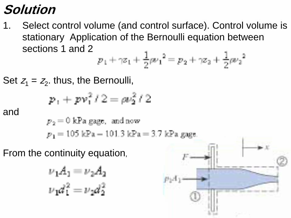
Solution 1. Select control volume (and control surface). Control volume is
stationary Application of the Bernoulli equation between
sections 1 and 2
Set z1 = z2. thus, the Bernoulli,
and
From the continuity equation,
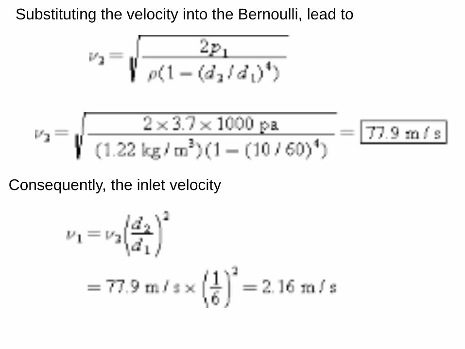
Substituting the velocity into the Bernoulli, lead to
Consequently, the inlet velocity
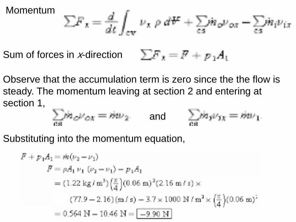
Momentum
Sum of forces in x-direction
Observe that the accumulation term is zero since the the flow is
steady. The momentum leaving at section 2 and entering at
section 1,
and
Substituting into the momentum equation,
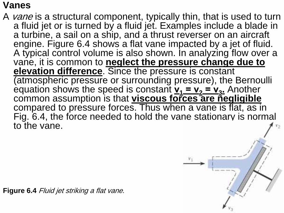
Vanes
A vane is a structural component, typically thin, that is used to turn a fluid jet or is turned by a fluid jet. Examples include a blade in a turbine, a sail on a ship, and a thrust reverser on an aircraft engine. Figure 6.4 shows a flat vane impacted by a jet of fluid. A typical control volume is also shown. In analyzing flow over a vane, it is common to neglect the pressure change due to elevation difference. Since the pressure is constant (atmospheric pressure or surrounding pressure), the Bernoulli equation shows the speed is constant ν1 = ν2 = ν3. Another common assumption is that viscous forces are negligible compared to pressure forces. Thus when a vane is flat, as in Fig. 6.4, the force needed to hold the vane stationary is normal to the vane.
Figure 6.4 Fluid jet striking a flat vane.
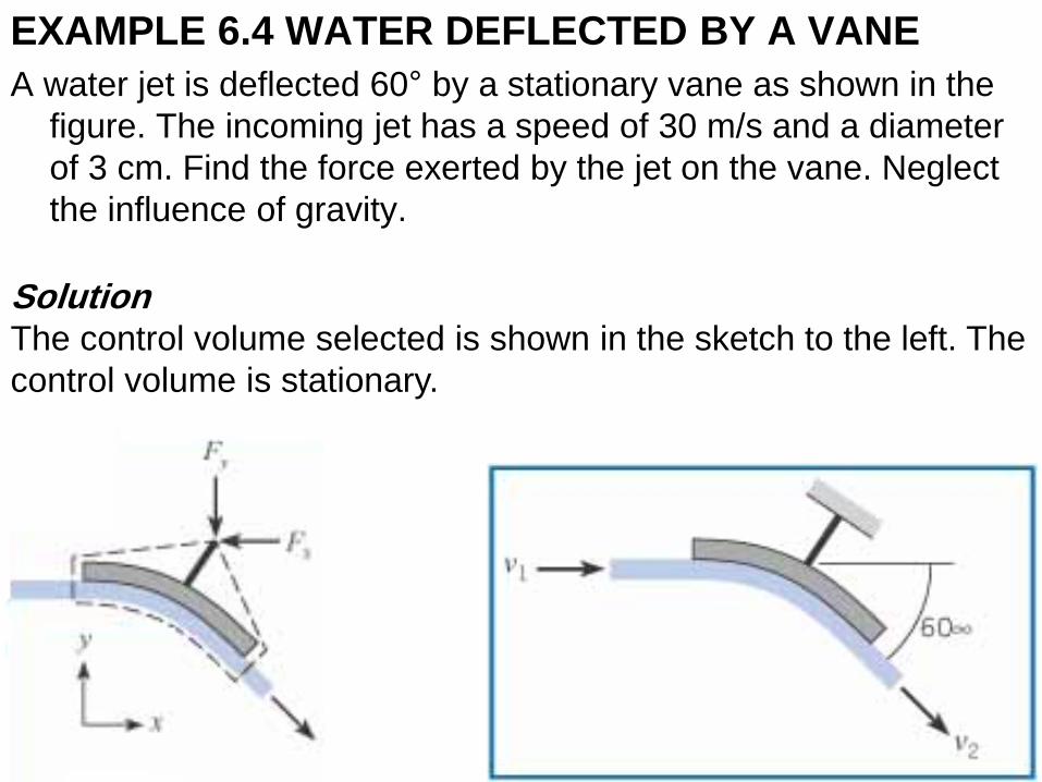
EXAMPLE 6.4 WATER DEFLECTED BY A VANE
A water jet is deflected 60° by a stationary vane as shown in the
figure. The incoming jet has a speed of 30 m/s and a diameter
of 3 cm. Find the force exerted by the jet on the vane. Neglect
the influence of gravity.
Solution The control volume selected is shown in the sketch to the left. The
control volume is stationary.
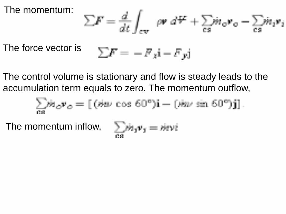
The momentum:
The force vector is
The control volume is stationary and flow is steady leads to the
accumulation term equals to zero. The momentum outflow,
The momentum inflow,
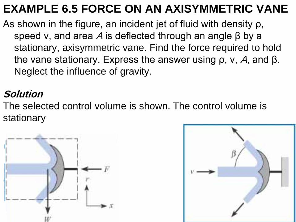
EXAMPLE 6.5 FORCE ON AN AXISYMMETRIC VANE
As shown in the figure, an incident jet of fluid with density ρ,
speed ν, and area A is deflected through an angle β by a
stationary, axisymmetric vane. Find the force required to hold
the vane stationary. Express the answer using ρ, ν, A, and β.
Neglect the influence of gravity.
Solution The selected control volume is shown. The control volume is
stationary
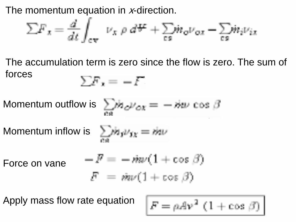
The momentum equation in x-direction.
The accumulation term is zero since the flow is zero. The sum of
forces
Momentum outflow is
Momentum inflow is
Force on vane
Apply mass flow rate equation
Pipe Bends
Calculating the force on pipe bends is important
in engineering applications using large pipes to
design the support system. Because flow in a
pipe is usually turbulent, it is common practice
to assume that velocity is nearly constant
across each cross section of the pipe. Also, the
force acting on a pipe cross section is given by
pA, where p is the pressure at the centroid of
area and A is area.
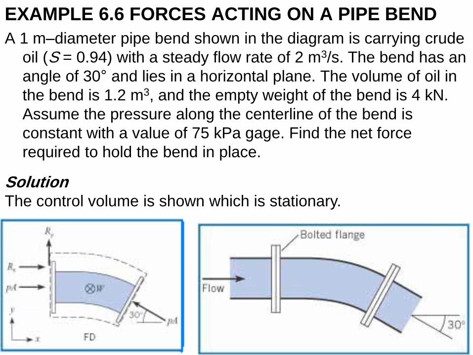
EXAMPLE 6.6 FORCES ACTING ON A PIPE BEND
A 1 m–diameter pipe bend shown in the diagram is carrying crude
oil (S = 0.94) with a steady flow rate of 2 m3/s. The bend has an
angle of 30° and lies in a horizontal plane. The volume of oil in
the bend is 1.2 m3, and the empty weight of the bend is 4 kN.
Assume the pressure along the centerline of the bend is
constant with a value of 75 kPa gage. Find the net force
required to hold the bend in place.
Solution The control volume is shown which is stationary.
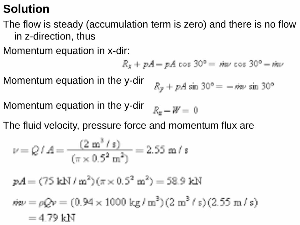
Solution
The flow is steady (accumulation term is zero) and there is no flow
in z-direction, thus
Momentum equation in x-dir:
Momentum equation in the y-dir
Momentum equation in the y-dir
The fluid velocity, pressure force and momentum flux are
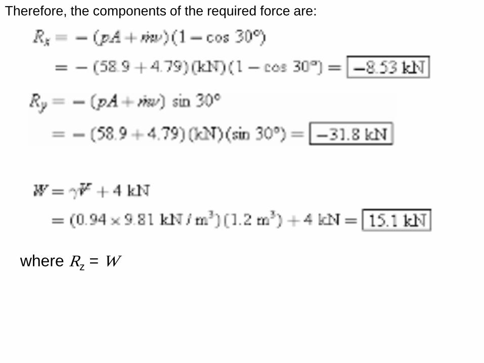
Therefore, the components of the required force are:
where Rz = W
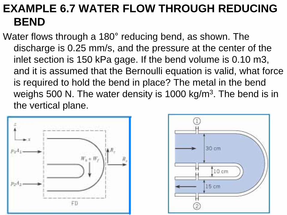
EXAMPLE 6.7 WATER FLOW THROUGH REDUCING
BEND
Water flows through a 180° reducing bend, as shown. The
discharge is 0.25 mm/s, and the pressure at the center of the
inlet section is 150 kPa gage. If the bend volume is 0.10 m3,
and it is assumed that the Bernoulli equation is valid, what force
is required to hold the bend in place? The metal in the bend
weighs 500 N. The water density is 1000 kg/m3. The bend is in
the vertical plane.
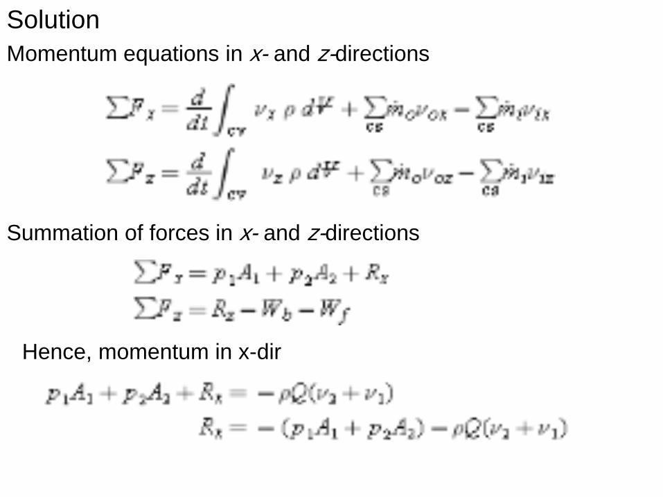
Solution
Momentum equations in x- and z-directions
Summation of forces in x- and z-directions
Hence, momentum in x-dir
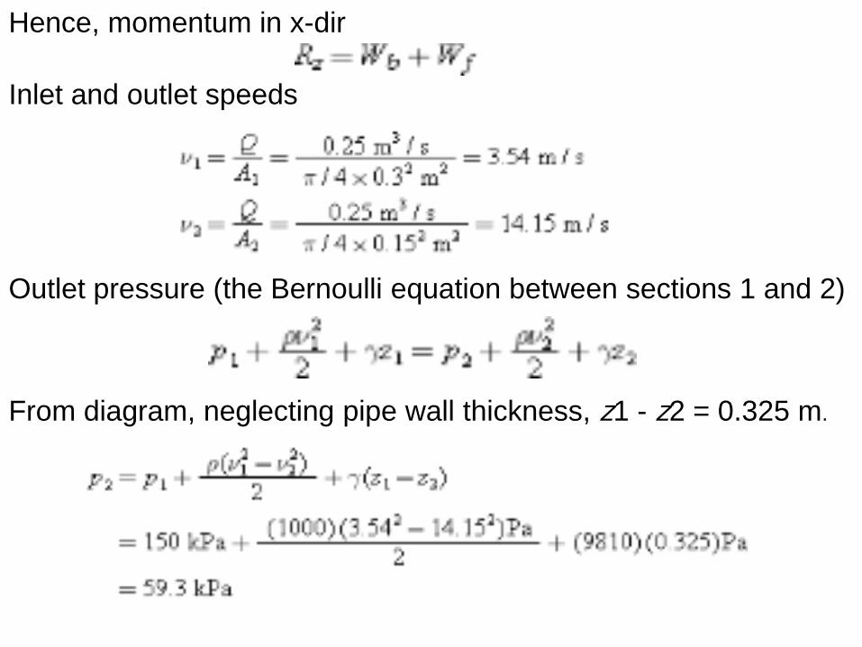
Hence, momentum in x-dir
Inlet and outlet speeds
Outlet pressure (the Bernoulli equation between sections 1 and 2)
From diagram, neglecting pipe wall thickness, z1 - z2 = 0.325 m.
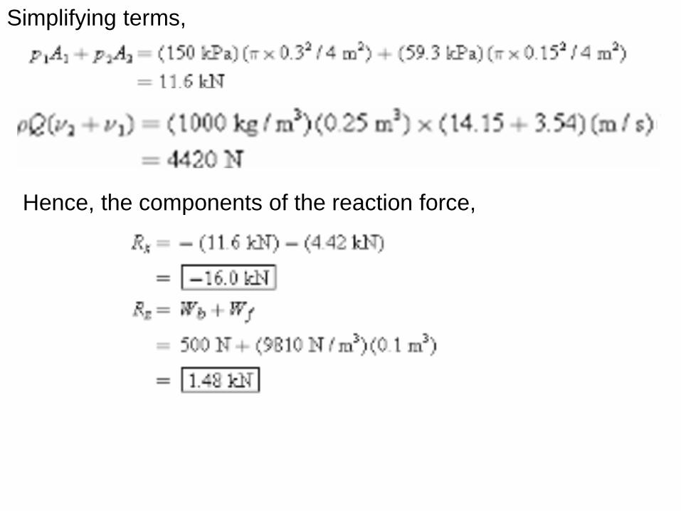
Simplifying terms,
Hence, the components of the reaction force,
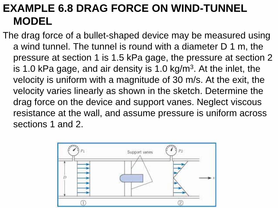
EXAMPLE 6.8 DRAG FORCE ON WIND-TUNNEL
MODEL
The drag force of a bullet-shaped device may be measured using
a wind tunnel. The tunnel is round with a diameter D 1 m, the
pressure at section 1 is 1.5 kPa gage, the pressure at section 2
is 1.0 kPa gage, and air density is 1.0 kg/m3. At the inlet, the
velocity is uniform with a magnitude of 30 m/s. At the exit, the
velocity varies linearly as shown in the sketch. Determine the
drag force on the device and support vanes. Neglect viscous
resistance at the wall, and assume pressure is uniform across
sections 1 and 2.
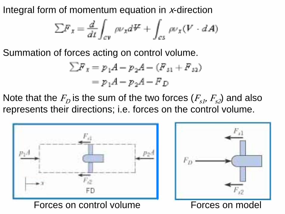
Forces on model Forces on control volume
Integral form of momentum equation in x-direction
Summation of forces acting on control volume.
Note that the FD is the sum of the two forces (Fs1, Fs2) and also
represents their directions; i.e. forces on the control volume.
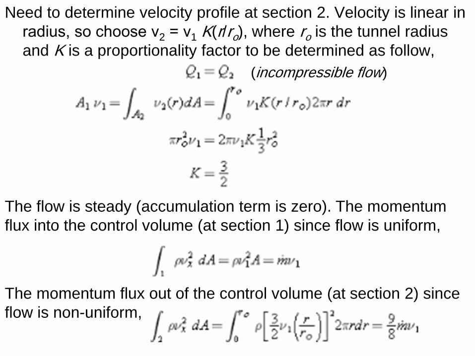
Need to determine velocity profile at section 2. Velocity is linear in
radius, so choose ν2 = ν1 K(r/ro), where ro is the tunnel radius
and K is a proportionality factor to be determined as follow,
The flow is steady (accumulation term is zero). The momentum
flux into the control volume (at section 1) since flow is uniform,
The momentum flux out of the control volume (at section 2) since
flow is non-uniform,
(incompressible flow)
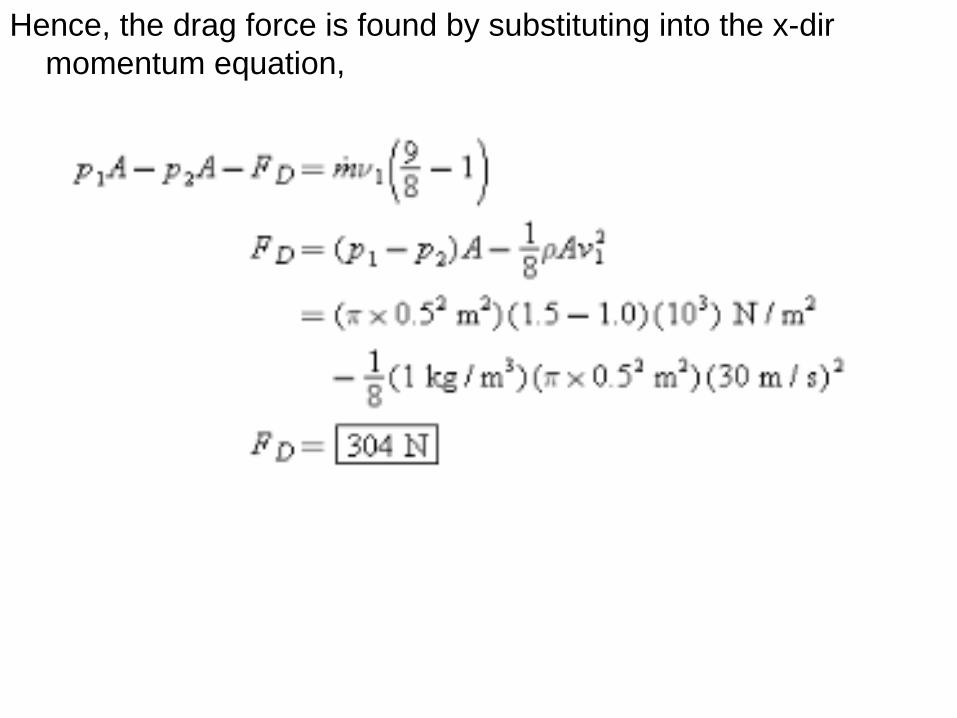
Hence, the drag force is found by substituting into the x-dir
momentum equation,
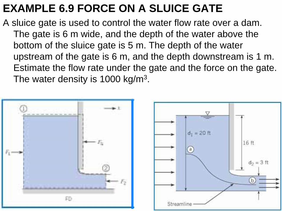
EXAMPLE 6.9 FORCE ON A SLUICE GATE
A sluice gate is used to control the water flow rate over a dam.
The gate is 6 m wide, and the depth of the water above the
bottom of the sluice gate is 5 m. The depth of the water
upstream of the gate is 6 m, and the depth downstream is 1 m.
Estimate the flow rate under the gate and the force on the gate.
The water density is 1000 kg/m3.
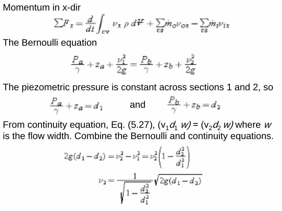
Momentum in x-dir
The Bernoulli equation
The piezometric pressure is constant across sections 1 and 2, so
and
From continuity equation, Eq. (5.27), (ν1d1 w) = (ν2d2 w) where w is the flow width. Combine the Bernoulli and continuity equations.
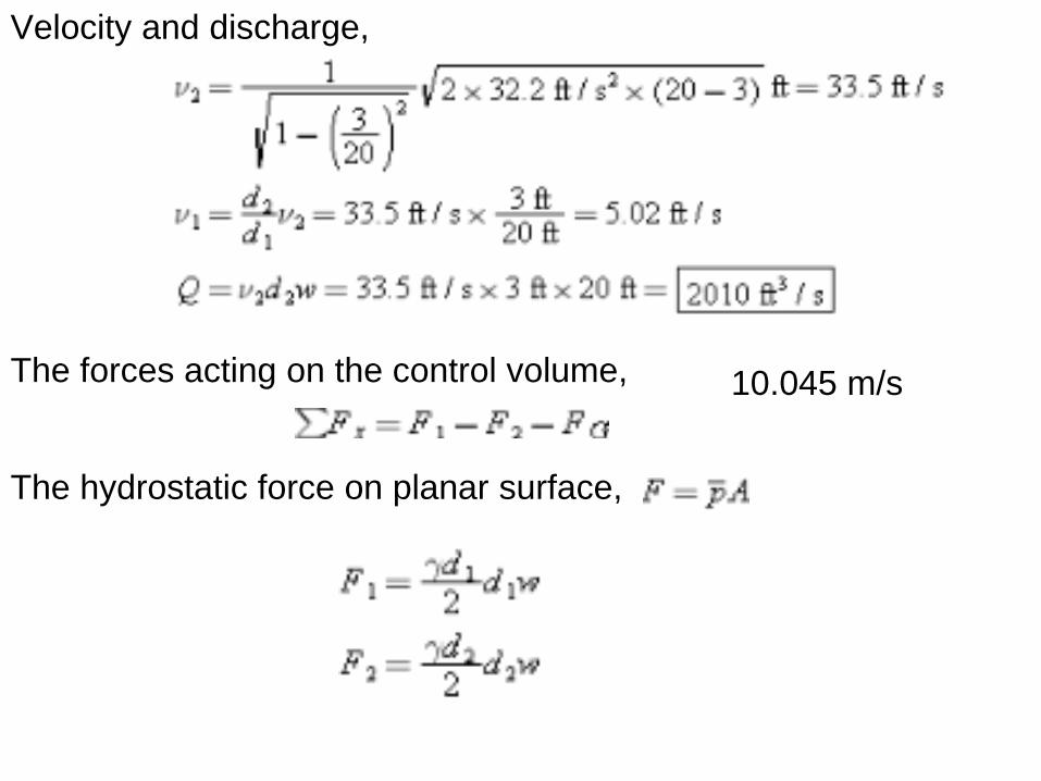
Velocity and discharge,
The forces acting on the control volume,
The hydrostatic force on planar surface,
10.045 m/s
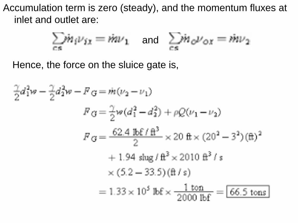
Accumulation term is zero (steady), and the momentum fluxes at
inlet and outlet are:
and
Hence, the force on the sluice gate is,
Moving Control Volumes All the applications of the momentum equation up to this point
have involved a stationary control volume. However, in some problems it may be more useful to attach the control volume to a moving body.
As discussed previously, the velocity v in the momentum equation must be relative to an inertial reference frame. When applying the momentum equation each mass flow rate is calculated using the velocity with respect to the control surface, but the velocity v must be evaluated with respect to an inertial reference frame.
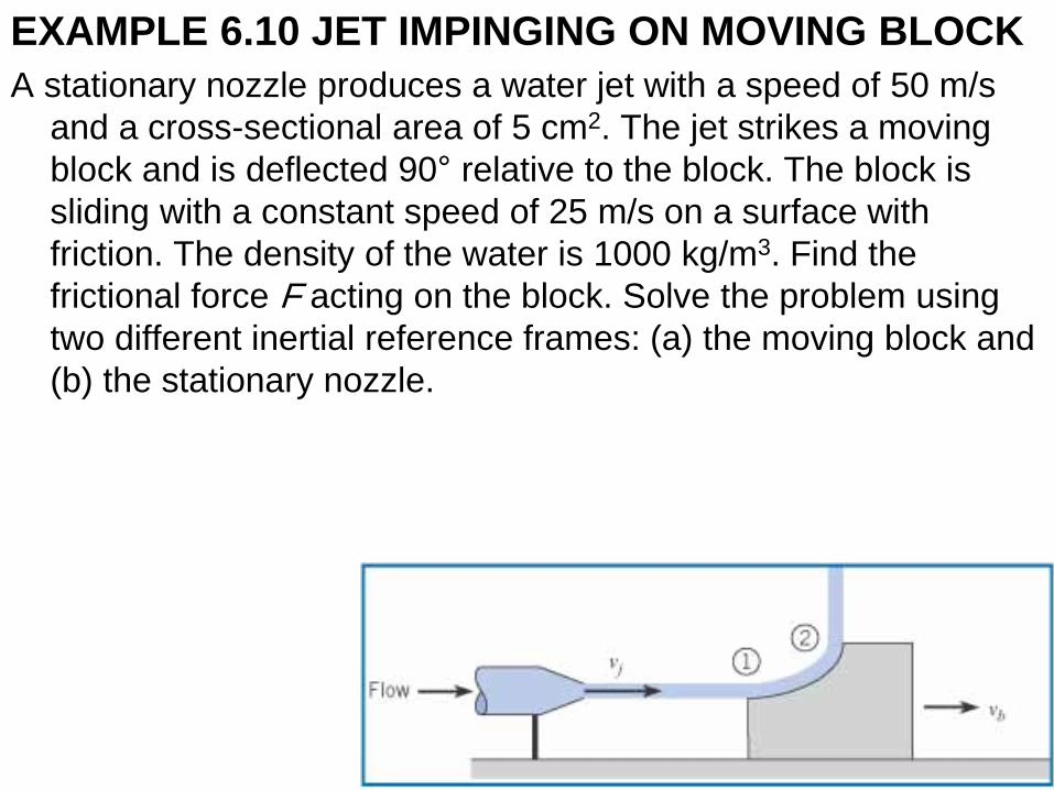
EXAMPLE 6.10 JET IMPINGING ON MOVING BLOCK
A stationary nozzle produces a water jet with a speed of 50 m/s
and a cross-sectional area of 5 cm2. The jet strikes a moving
block and is deflected 90° relative to the block. The block is
sliding with a constant speed of 25 m/s on a surface with
friction. The density of the water is 1000 kg/m3. Find the
frictional force F acting on the block. Solve the problem using
two different inertial reference frames: (a) the moving block and
(b) the stationary nozzle.
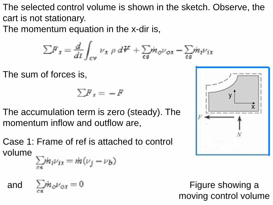
Figure showing a
moving control volume
The selected control volume is shown in the sketch. Observe, the
cart is not stationary.
The momentum equation in the x-dir is,
The sum of forces is,
The accumulation term is zero (steady). The
momentum inflow and outflow are,
and
Case 1: Frame of ref is attached to control
volume
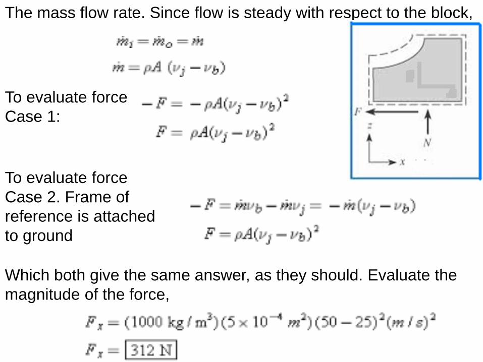
The mass flow rate. Since flow is steady with respect to the block,
To evaluate force
Case 1:
To evaluate force
Case 2. Frame of
reference is attached
to ground
Which both give the same answer, as they should. Evaluate the
magnitude of the force,
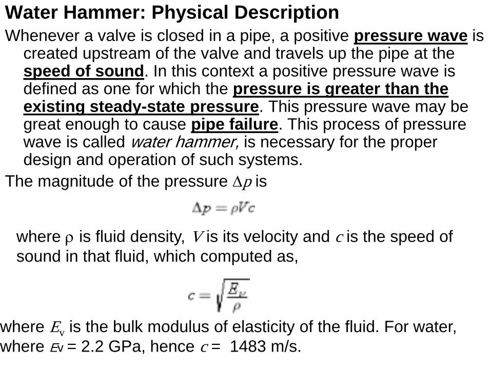
Water Hammer: Physical Description Whenever a valve is closed in a pipe, a positive pressure wave is
created upstream of the valve and travels up the pipe at the speed of sound. In this context a positive pressure wave is defined as one for which the pressure is greater than the existing steady-state pressure. This pressure wave may be great enough to cause pipe failure. This process of pressure wave is called water hammer, is necessary for the proper design and operation of such systems.
The magnitude of the pressure Dp is
where r is fluid density, V is its velocity and c is the speed of
sound in that fluid, which computed as,
where Ev is the bulk modulus of elasticity of the fluid. For water,
where Ev = 2.2 GPa, hence c = 1483 m/s.
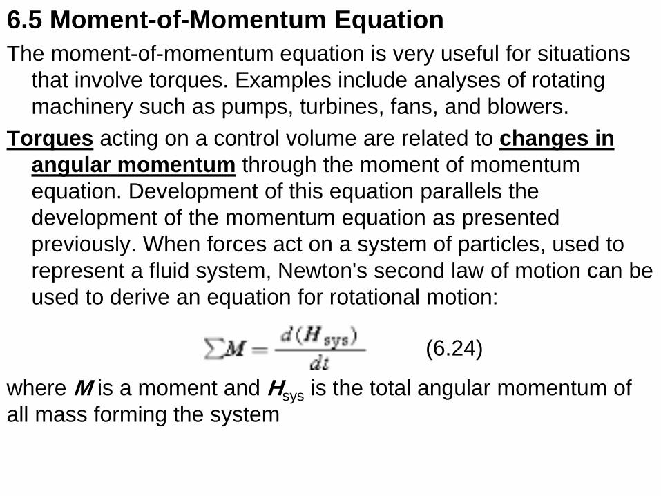
6.5 Moment-of-Momentum Equation
The moment-of-momentum equation is very useful for situations
that involve torques. Examples include analyses of rotating
machinery such as pumps, turbines, fans, and blowers.
Torques acting on a control volume are related to changes in
angular momentum through the moment of momentum
equation. Development of this equation parallels the
development of the momentum equation as presented
previously. When forces act on a system of particles, used to
represent a fluid system, Newton's second law of motion can be
used to derive an equation for rotational motion:
where M is a moment and Hsys is the total angular momentum of
all mass forming the system
(6.24)
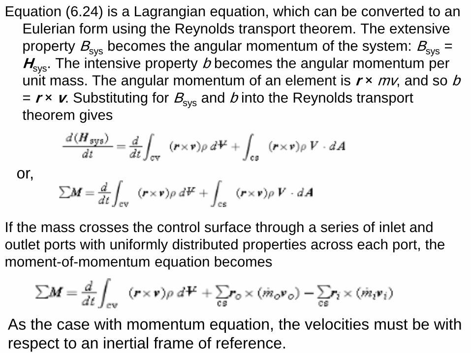
Equation (6.24) is a Lagrangian equation, which can be converted to an
Eulerian form using the Reynolds transport theorem. The extensive
property Bsys becomes the angular momentum of the system: Bsys =
Hsys. The intensive property b becomes the angular momentum per
unit mass. The angular momentum of an element is r × mv, and so b = r × v. Substituting for Bsys and b into the Reynolds transport
theorem gives
or,
If the mass crosses the control surface through a series of inlet and
outlet ports with uniformly distributed properties across each port, the
moment-of-momentum equation becomes
As the case with momentum equation, the velocities must be with
respect to an inertial frame of reference.
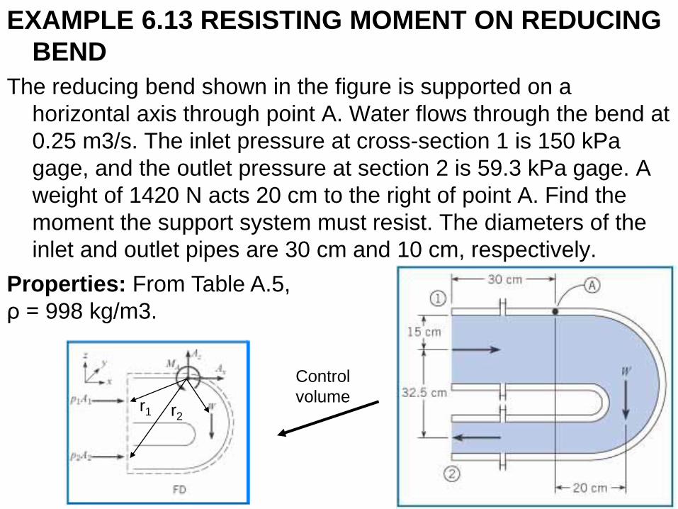
EXAMPLE 6.13 RESISTING MOMENT ON REDUCING
BEND
The reducing bend shown in the figure is supported on a
horizontal axis through point A. Water flows through the bend at
0.25 m3/s. The inlet pressure at cross-section 1 is 150 kPa
gage, and the outlet pressure at section 2 is 59.3 kPa gage. A
weight of 1420 N acts 20 cm to the right of point A. Find the
moment the support system must resist. The diameters of the
inlet and outlet pipes are 30 cm and 10 cm, respectively.
Properties: From Table A.5,
ρ = 998 kg/m3.
Control
volume r1 r2
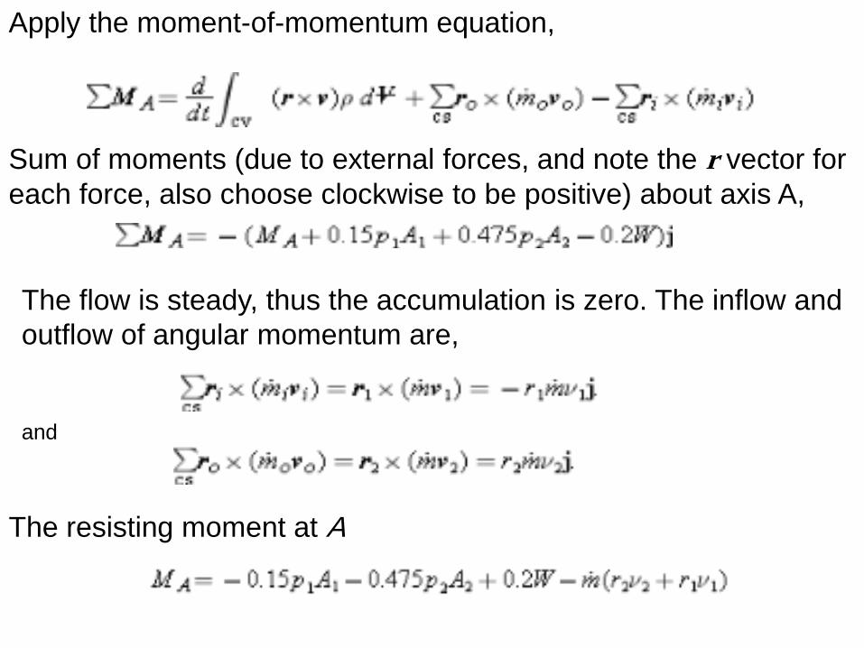
Apply the moment-of-momentum equation,
Sum of moments (due to external forces, and note the r vector for
each force, also choose clockwise to be positive) about axis A,
The flow is steady, thus the accumulation is zero. The inflow and
outflow of angular momentum are,
and
The resisting moment at A
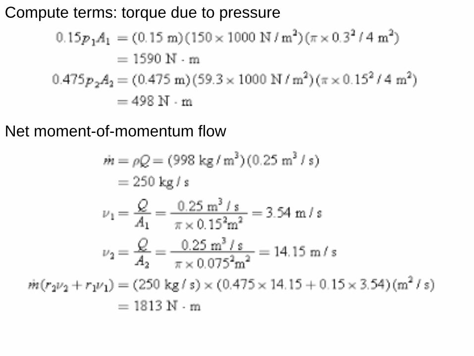
Compute terms: torque due to pressure
Net moment-of-momentum flow
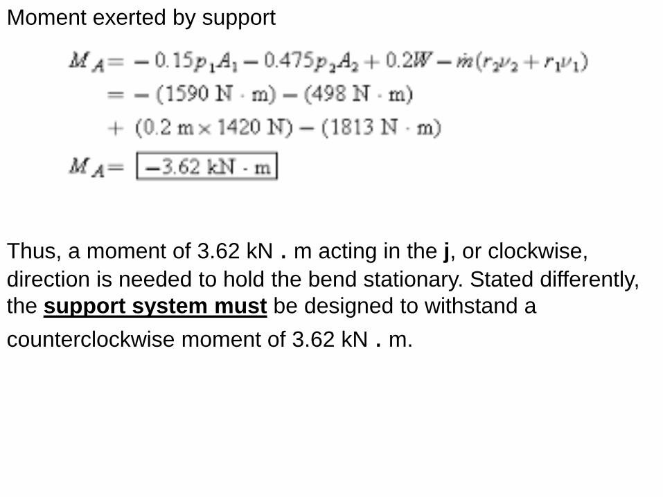
Moment exerted by support
Thus, a moment of 3.62 kN . m acting in the j, or clockwise,
direction is needed to hold the bend stationary. Stated differently,
the support system must be designed to withstand a
counterclockwise moment of 3.62 kN . m.
6.6 Navier-Stokes Equation
The continuity equation at a point in the flow was derived using a control volume of infinitesimal size (chapter 5). The resulting differential equation is an independent equation in the analysis of fluid flow. The same approach can be applied to the momentum equation, yielding the differential equation for momentum at a point in the flow. For simplicity, the derivation will be restricted to a two-dimensional planar flow, and the extension to three dimensions will be outlined.
Consider the infinitesimal control volume shown in Fig. 6.10a. The dimensions of the control volume are Dx and Dy, and the dimension in the third direction (normal to page) is taken as unity. Assume that the center of the control volume is fixed with respect to the coordinate system and that the coordinate system is an inertial reference frame. Also assume that the control surfaces are fixed with respect to the coordinate system. The
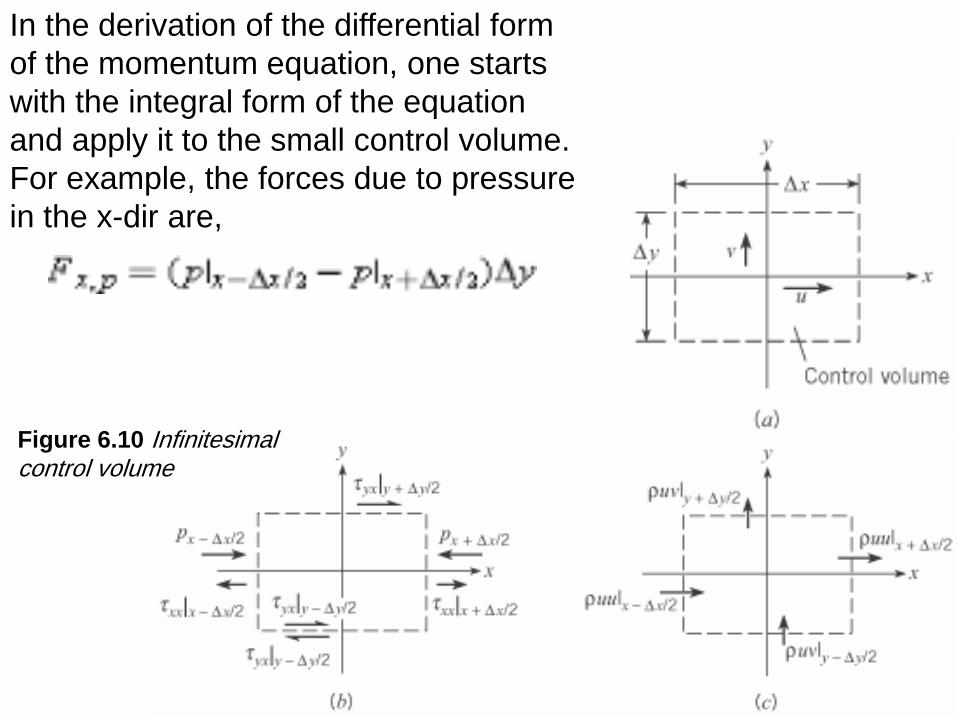
Figure 6.10 Infinitesimal control volume
In the derivation of the differential form
of the momentum equation, one starts
with the integral form of the equation
and apply it to the small control volume.
For example, the forces due to pressure
in the x-dir are,
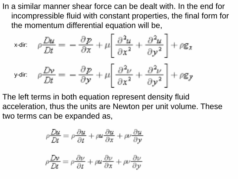
In a similar manner shear force can be dealt with. In the end for
incompressible fluid with constant properties, the final form for
the momentum differential equation will be,
x-dir:
y-dir:
The left terms in both equation represent density fluid
acceleration, thus the units are Newton per unit volume. These
two terms can be expanded as,
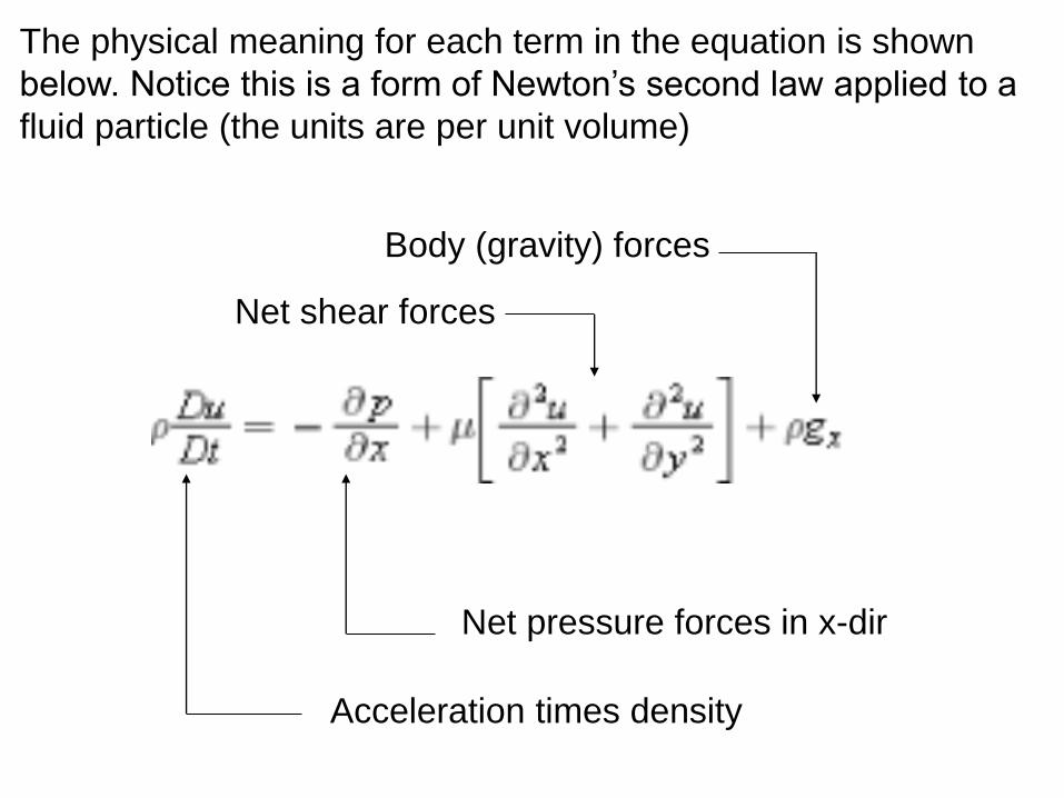
The physical meaning for each term in the equation is shown
below. Notice this is a form of Newton’s second law applied to a
fluid particle (the units are per unit volume)
Acceleration times density
Net pressure forces in x-dir
Net shear forces
Body (gravity) forces
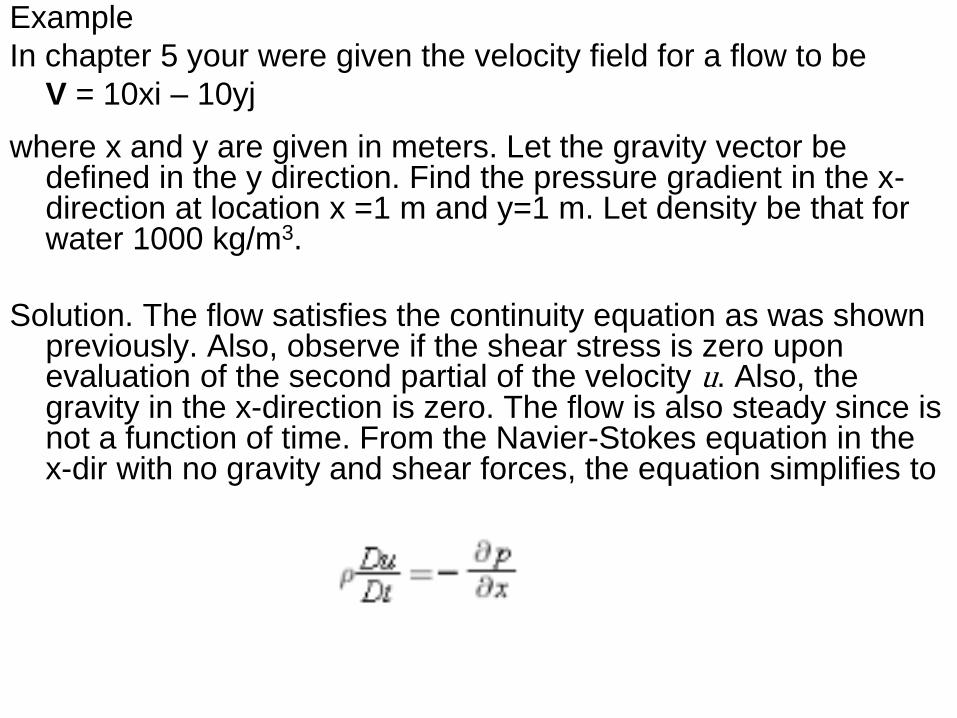
Example
In chapter 5 your were given the velocity field for a flow to be
V = 10xi – 10yj
where x and y are given in meters. Let the gravity vector be defined in the y direction. Find the pressure gradient in the x-direction at location x =1 m and y=1 m. Let density be that for water 1000 kg/m3.
Solution. The flow satisfies the continuity equation as was shown previously. Also, observe if the shear stress is zero upon evaluation of the second partial of the velocity u. Also, the gravity in the x-direction is zero. The flow is also steady since is not a function of time. From the Navier-Stokes equation in the x-dir with no gravity and shear forces, the equation simplifies to
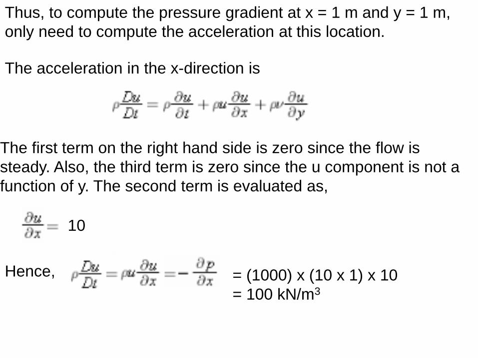
The acceleration in the x-direction is
The first term on the right hand side is zero since the flow is
steady. Also, the third term is zero since the u component is not a
function of y. The second term is evaluated as,
10
Hence, = (1000) x (10 x 1) x 10
= 100 kN/m3
Thus, to compute the pressure gradient at x = 1 m and y = 1 m,
only need to compute the acceleration at this location.
![PRESSURE TESTING [1] การตรวจสอบโดยใช้แรงดันdacon-inspection.com/wp-content/uploads/2013/04/Pressure-Testing.pdf · Hydrostatic Pressure](https://img.pdfslide.tips/doc/110x75/5b0c01517f8b9a8b038b7246/pressure-testing-1-dacon-.jpg)