Embed Size (px)
Citation preview
A Project Report on
FLUIDIZED BED COMBUSTIONS FOR ENERGY CONVERSIONS
In
Advanced Energy Systems
Under the Guidance of
Dr. Ramazan Asmatulu
Submitted by
Shravani Kasaragadda (W268D427)
Goutham Chinni (K474R658)
Gopi Krishna Mandadi (K353X443)
1
CONTENTS
Abstract
List of figures
1. Introduction General Background
Motivation
Objectives
2. Literature Review
3. Experimental Materials
Methods
4. Results & Discussion
5. Conclusions
6. Future work
7. References
2
Abstract
A fluidized bed is a unique reactor where the fuel that is smoldered is kept up in movement,
coursing in a smooth movement keeping in mind the end goal to burn completely. This
procedure builds the productivity of the reactor, and, all the more significantly, lessens the
aggregate greenhouse gas and particulate outflows. Burning coal with biomass in a fluidized bed
diminishes destructive discharges from the ignition of these powers independently while in the
meantime lessens the nursery gas outflows from the coal. This innovation has bit by bit enhanced
and is currently sent on a business premise. On the other hand, proceeded with R&D in this field
is expected to further enhance fuel burning effectiveness, keeping up high fuel adaptability at
stringent greenhouse gas limits. Co-operation between scientists, modern agents and
administrative projects quickens the information base and innovation organization. With the
developing vitality requests in the force part, Fluidized bed combustion (FBC) innovation is
ceaselessly picking up significance because of its capacity to smolder distinctive second rate
coals and the nonattendance of NOx creation. Research needs on the point of fluidization are
essentially identified with blending of fuel, solids furthermore, gas, including entrance and
blending of auxiliary air. The bigger the cross area of the heater, the more basic is the fuel
blending, i.e. this is basic for expansive power boilers. For little and medium scale FBC boilers
smoldering waste and waste inferred powers, there is likewise a need to comprehend fuel and gas
blending keeping in mind the end goal to be ready to bring down the overabundance air
proportion and, along these lines, to build the effectiveness.
3
1. INTRODUCTION
General Background
Fluidized bed combustion (FBC) is a technology used for generation of heat, power and a
combination of these. It is a unique reactor where the fuel is burned and maintained in motion,
circulating in a fluid motion in order to burn thoroughly. There has been a consistent
advancement and refinement of the innovation since it came to business status in the mid 80's.
As for the improvement of the innovation, two elements can be specified which to a sure degree
make the FBC advancement contrast from that of other strong fuel burning advances. In the first
place, the fuel adaptability, which is one of the fundamental points of interest of the innovation,
has put concentrate on distinctive fills after some time subsequent to the presentation of the FBC
innovation. It has been reported that it is one of the most efficient and suitable process for
converting the agricultural and food residues into energy. The bed furnaces were introduced
around 25-30 years ago, and the refractory materials such as sand or limestone are suspended by
air currents and they are the medium for the heat transfer to the biomass fuel. Fuel flexibility is
one of the main advantages of the technology. Development of fluidized bed combustion
technology development is different in different regions of the world, depending on the fluid
availability. Depending on the type of fuels, the technology demands differently.
There are 2 main applications of the FBC technology is that, 1. Combined heat and power (CHP)
that burns renewable and waste fuels and 2. Large power boilers mainly coal yield different
problems and challenges. There are 2 types of fluidized bed boilers they are, 1. Bubbling
fluidized bed and 2. Circulating fluidized beds which operate under the atmospheric conditions.
4
Objectives
Fluidization
Fluidization is a procedure like liquefaction whereby a granular material is changed over from a
static strong like state to a dynamic liquid like state. This procedure happens when a liquid (fluid
or gas) is left behind through the granular material. Whenever a gas stream is presented through
the base of a bed of strong particles, it will move upwards through the bed by means of the
unfilled spaces between the particles. At low gas speeds, streamlined delay every molecule is
likewise low, and along these lines the bed stays in a settled state. Expanding the speed, the
streamlined drag powers will start to check the gravitational powers, making the bed grow in
volume as the particles move far from one another. Further expanding the speed, it will achieve a
basic worth at which the upward drag powers will precisely measure up to the descending
gravitational powers, bringing about the particles to end up suspended inside of the liquid. At
this basic esteem, the bed is said to be fluidized and will display fluidic conduct. By further
expanding gas speed, the mass thickness of the bed will keep on diminishing, and its fluidization
turns out to be more vicious, until the particles no more shape a quaint little inn "passed on"
upwards by the gas stream. Whenever fluidized, a bed of strong particles will carry on as a
liquid, similar to a fluid or gas. Like water in a basin: the bed will adjust to the volume of the
chamber, its surface remaining opposite to gravity; objects with a lower thickness than the bed
thickness will skim on its surface, swaying here and there if pushed downwards, while objects
with a higher thickness sink to the base of the bed. The fluidic conduct permits the particles to be
transported like a liquid, diverted through channels, not requiring mechanical transport. A
rearranged each day-life sample of a gas-strong fluidized bed would be a hot-air popcorn popper.
The popcorn portions, all being genuinely uniform fit as a fiddle, are suspended in the hot air
5
ascending from the base chamber. As a result of the serious blending of the particles, similar to
that of a bubbling fluid, this takes into account a uniform temperature of the bits all through the
chamber, minimizing the measure of blazed popcorn. Subsequent to popping, the now bigger
popcorn particles experience expanded streamlined drag which pushes them out of the chamber
and into a dish.
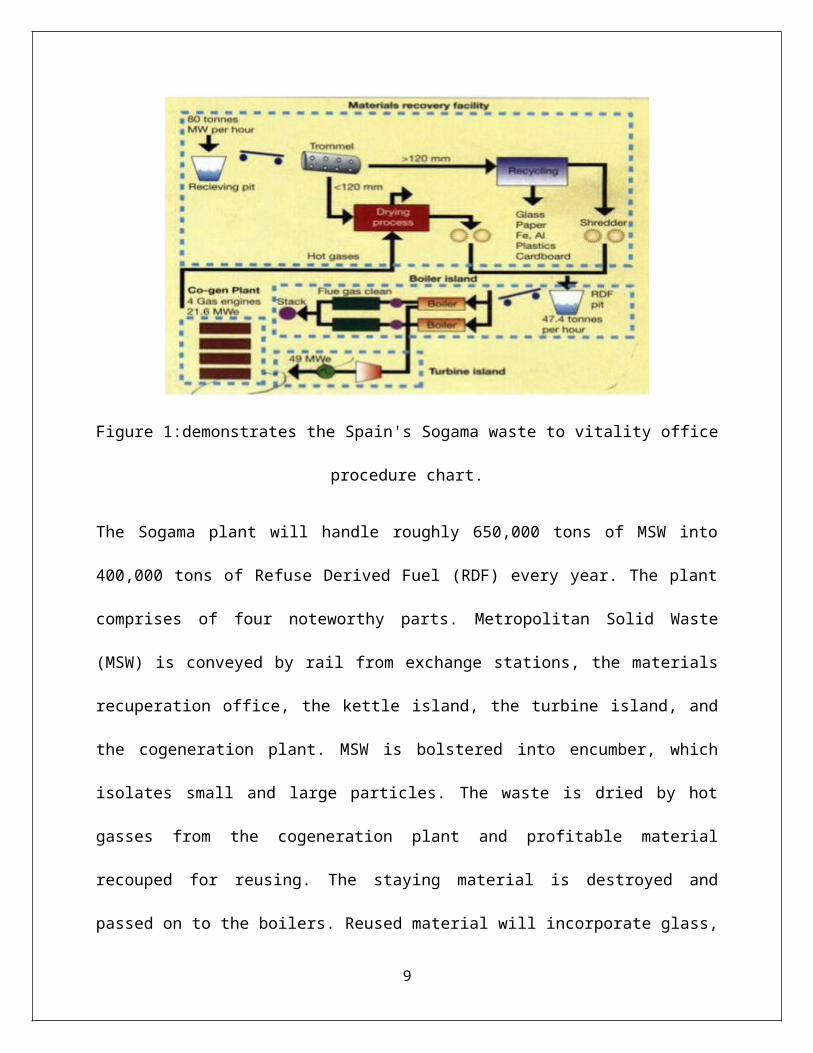
Figure 1:demonstrates the Spain's Sogama waste to vitality office procedure chart.
The Sogama plant will handle roughly 650,000 tons of MSW into 400,000 tons of Refuse
Derived Fuel (RDF) every year. The plant comprises of four noteworthy parts. Metropolitan
Solid Waste (MSW) is conveyed by rail from exchange stations, the materials recuperation
office, the kettle island, the turbine island, and the cogeneration plant. MSW is bolstered into
encumber, which isolates small and large particles. The waste is dried by hot gasses from the
cogeneration plant and profitable material recouped for reusing. The staying material is
destroyed and passed on to the boilers. Reused material will incorporate glass, paper, iron,
aluminum, plastics, and cardboard. A heater consolidating to 75 MW and Circulating Fluidized
6
Bed (CFB) boilers, a dry vent gas cleaning framework and a pack house channel. This segment
represents 33% of the aggregate expense of the plant.
Efficiency of the Combustion Process
Fluidized-bed boilers are the most well-known kind of heater suggested for biomass fuel, which
is blazed inside of a hot bed of idle particles, commonly sand. The fuel-molecule blend is
suspended by an upward stream of burning air inside of the bed. As speeds build the gas/strong
blend displays liquid like properties. As per the EPA's "Consolidated Heat and Power
Partnership Biomass CHP Catalog," the scouring activity of the bed material on the fuel likewise
upgrades the stripping so as to burn procedure "away the CO2 and solids buildup (scorch) that
ordinarily conforms to the fuel particles. Permitting oxygen to achieve the ignitable material all
the more promptly and build the rate and proficiency of the burning procedure."
This procedure additionally builds warmth exchange and takes into consideration lower working
temperatures: bed temperatures range around 1,400° F to 1,600° F, far not exactly the 2,200° F
for a spreader stoker kettle. Lower heater temperatures additionally create less nitrogen oxide, an
ecological and administrative advantage when smoldering high nitrogen-content wood and
biomass powers. Sulfur dioxide emanations from wood waste and biomass are for the most part
unimportant; be that as it may, if sulfur is a contaminant it can be killed by adding limestone to
the fluid bed.
7
2. Literature review
https://www.academia.edu/3144562/
Fine_Particle_Emissions_During_Fluidized_Bed_Combustion_of_Coal_and_Waste-
Derived_Fuels
Fluidized Bed Combustion
Beside suspension terminating of wood, the most effective technique for straightforwardly
smoldering biomass is in a fluidized bed combustor (FBC). This is additionally the most flexible
since the framework can adapt to an extensive variety of powers and a scope of dampness
substance. The premise for a FBC framework is a bed of a latent mineral, for example, sand or
limestone through which air is blown from beneath. The air is pumped through the bed in
adequate volume and at a sufficiently high weight to entrain the little particles of the bed material
so that they act much like a liquid.
The burning assembly of a fluidized bed plant is molded so that over a sure stature the air speed
drops beneath that important to entrain the particles. This holds the greater part of the entrained
bed material towards the base of the chamber. When the bed gets to be hot, ignitable material
brought into it will blaze, creating warmth as in a more routine heater. The extent of flammable
material, for example, biomass inside of the bed is ordinarily just around 5%. There are diverse
outlines of FBC framework which include varieties around this standard. The most regular for
biomass burning is the flowing fluidized bed which consolidates a tornado channel to discrete
strong material from the hot pipe gasses which leave the fumes of the heater. The solids from the
channel are re-coursed into the bed, subsequently the name. The fluidized bed has two
unmistakable focal points for biomass ignition: First, it is the capacity to smolder an assortment
of diverse powers without influencing execution. Second is the capacity to bring compound
8
reactants into the fluidized bed to evacuate conceivable poisons. In FBC plants smoldering coal,
for instance, limestone can be added to catch sulfur and keep its discharge to the climate as sulfur
dioxide. Biomass has a tendency to contain less sulfur than coal so this system may not be
essential in a biomass plant.
A fluidized bed kettle can consume wood with to 55% dampness. One specific application is in
plants intended to smolder chicken litter, the decline from the serious cultivating of poultry.
Force stations have been fabricated that are dedicated particularly to this fuel source and these
plants use FBCs. Of the four unique sorts of ignition advances examined over, the FBC
innovation is most appropriate for a scope of little and medium scale operation for joined warmth
and force. With mechanical progressions the FBC boilers give effectiveness of as high as 80-
82% and can be utilized for a wide assortment of powers.
9
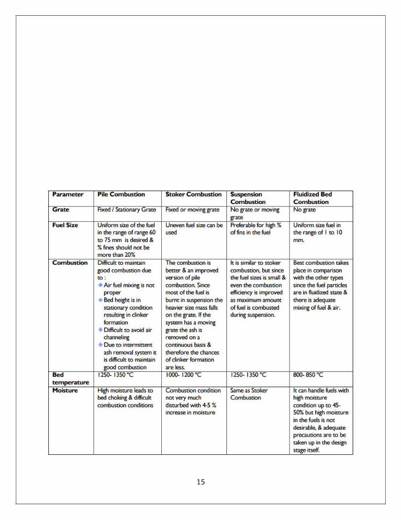
Comparasion of different types of conversion technologies
10
11
Mechanism Of Fluidised Bed mechanism
At the point when an uniformly dispersed air or gas is gone upward through a finely isolated bed
of strong particles, for example, sand bolstered on a fine work, the particles stay undisturbed at
low speeds. As the air speed is bit by bit expanded, a stage is come to when the person particles
are suspended noticeable all around stream and the bed is called "fluidized". With further
increment in air speed, there is air pocket development, overwhelming turbulence, fast blending
and development of thick characterized bed surface. The bed of strong particles shows the
properties of a bubbling fluid and accept the presence of a liquid – "percolating fluidized bed".
At higher speeds, air pockets vanish, and particles are extinguished of the bed. Along these lines,
a few measures of particles must be re-circled to keep up a steady framework and is called as
"circulating fluidized bed". This guideline of fluidization is shown in Figure. Fluidization
depends to a great extent on the molecule size and the air speed. The mean solids speed
increments at a slower rate than does the gas speed. The distinction between the mean strong
speed and mean gas speed is called as slip speed. Most extreme slip speed between the solids and
the gas is attractive for good warmth exchange and cozy contact. In the event that sand particles
in fluidized state are warmed to the ignition temperatures of fuel (rice husk, coal or bagasse),
12
what's more, fuel is infused persistently into the bed, the fuel will blaze quickly and the bed
accomplishes a uniform temperature.
The fluidized bed burning (FBC) happens at around 840°C to 950°C. Since this temperature is
much beneath the cinder combination temperature, liquefying of fiery debris and related issues
are maintained a strategic distance from. The lower ignition temperature is accomplished as a
result of high coefficient of warmth exchange because of fast blending in the fluidized quaint
little inn extraction of heat from the bed through in-bed warmth exchange tubes and dividers of
the bed. The gas speed is kept up between least fluidization speed and molecule entrainment
speed. This guarantees a steady operation of the overnight boardinghouse molecule entrainment
in the gas stream.
Fig 2: principle of fluidization
13
Any ignition procedure requires three "T"s - that is Time, Temperature and Turbulence. In FBC,
turbulence is advanced by fluidization. Enhanced blending produces equitably circulated heat at
lower temperature. Living arrangement time is ordinarily higher than traditional mesh
terminating. In this manner a FBC framework discharges warm all the more productively at
lower temperatures. Since limestone can likewise be utilized as molecule bed (on the off chance
that the fuel with sulfur substance is utilized), control of SOx and NOx emanations in the
burning chamber is accomplished with no extra control hardware. This is one of the real
favorable circumstances over conventional boilers.
Types of FBC Boiler’s
There are three basic types of fluidized bed combustion boilers:
1. Atmospheric Fluidized Bed Combustion System (AFBC)
2. Atmospheric circulating (fast) Fluidized Bed Combustion system (CFBC)
3. Pressurized Fluidized Bed Combustion System (PFBC).
14
3.MATERIALS AND METHODS:
https://www.academia.edu/3144562/
Fine_Particle_Emissions_During_Fluidized_Bed_Combustion_of_Coal_and_Waste-
Derived_Fuels.
Fluidized bed combustion (FBC) is today an entrenched innovation for era of warmth, force and
a mix of these. Yet, there has been a steady advancement and refinement of the innovation since
it came to business status in the mid 80's. As for the improvement of the innovation, two
variables can be specified which to a sure degree make the FBC advancement vary from that of
other strong fuel ignition advances. To start with, the fuel adaptability, which is one of the
primary focal points of the innovation, has put concentrate on distinctive powers after some time
subsequent to the presentation of the FBC innovation. The center of the advancement has
additionally been diverse in distinctive locales of the world, contingent upon accessibility. In this
manner, the different sorts of fills yield distinctive requests on the innovation (significance of
blending, material issues, warmth exchange conveyance and so on.). Besides, the two principle
utilizations of the FBC innovation, littler warmth just or joined warmth and force (CHP) boilers
15
copying renewable and waste powers and expansive force boilers for the most part copying coal
yield distinctive issues and difficulties, as talked about underneath.
(http://www.unep.org/climatechange/mitigation/Portals/93/documents/EnergyEfficiency/
FBC_30_sep_2007.pdf)
Fixing, bubbling and fast fluidized beds
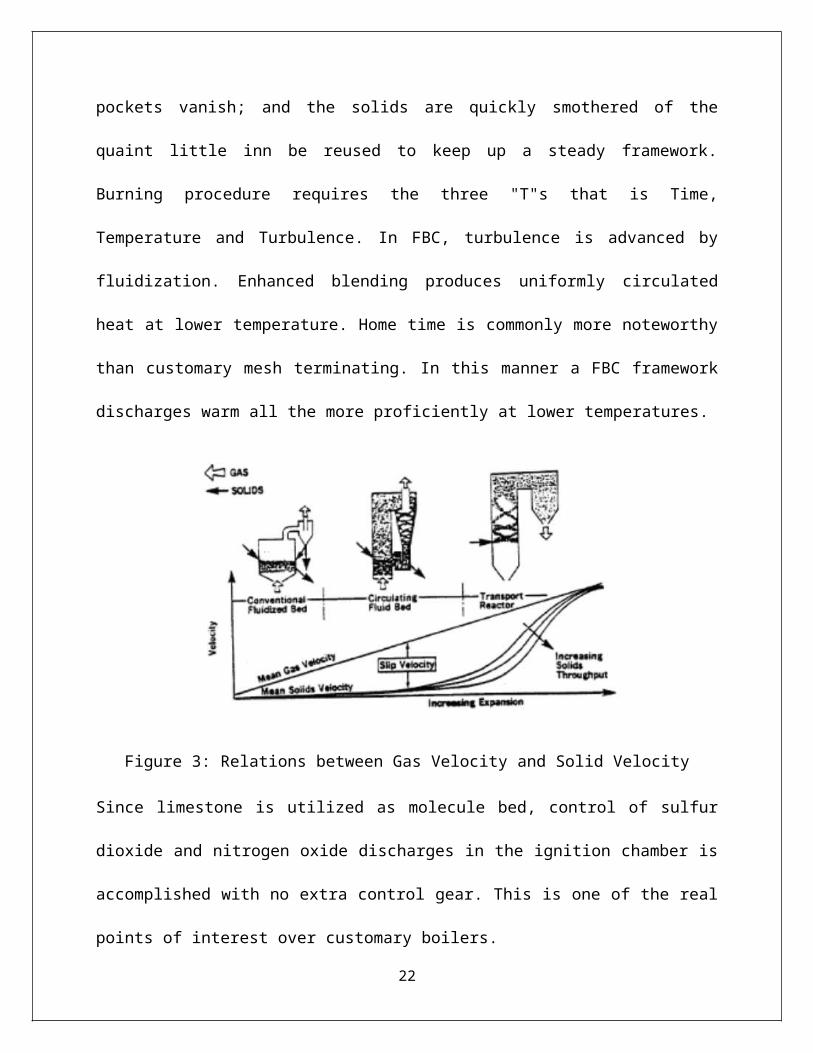
As the speed of a gas coursing through a bed of particles builds, a quality is ranges when the bed
fluidizes and air pockets structure as in a bubbling fluid. At higher speeds the air pockets vanish;
and the solids are quickly smothered of the quaint little inn be reused to keep up a steady
framework. Burning procedure requires the three "T"s that is Time, Temperature and
Turbulence. In FBC, turbulence is advanced by fluidization. Enhanced blending produces
uniformly circulated heat at lower temperature. Home time is commonly more noteworthy than
customary mesh terminating. In this manner a FBC framework discharges warm all the more
proficiently at lower temperatures.
Figure 3: Relations between Gas Velocity and Solid Velocity
16
Since limestone is utilized as molecule bed, control of sulfur dioxide and nitrogen oxide
discharges in the ignition chamber is accomplished with no extra control gear. This is one of the
real points of interest over customary boilers.
AFBC / Bubbling Bed
In AFBC, coal is pounded to a size of 1 – 10 mm relying upon the rank of coal, kind of fuel
encourage and bolstered into the ignition chamber. The air, which goes about as both the
fluidization air and burning air, is conveyed at a weight and moves through the bed in the wake
of being preheated by the fumes vent gasses. The speed of fluidizing air is in the scope of 1.2 to
3.7 m/sec. The rate at which air is blown through the bed decides the measure of fuel that can be
responded.
All AFBC/foaming bed boilers use in-bed evaporator tubes in the bed of limestone, sand and fuel
for extricating the warmth from the bed to keep up the bed temperature. The bed profundity is
typically 0.9 m to 1.5 m profound and the weight drop midpoints around 1 inch of water for
every inch of bed profundity. Next to no material leaves the foaming bed – just around 2 to 4 kg
of solids are reused per ton of fuel blazed. Regular fluidized bed combustors of this sort are
appeared in underneath figures.
17
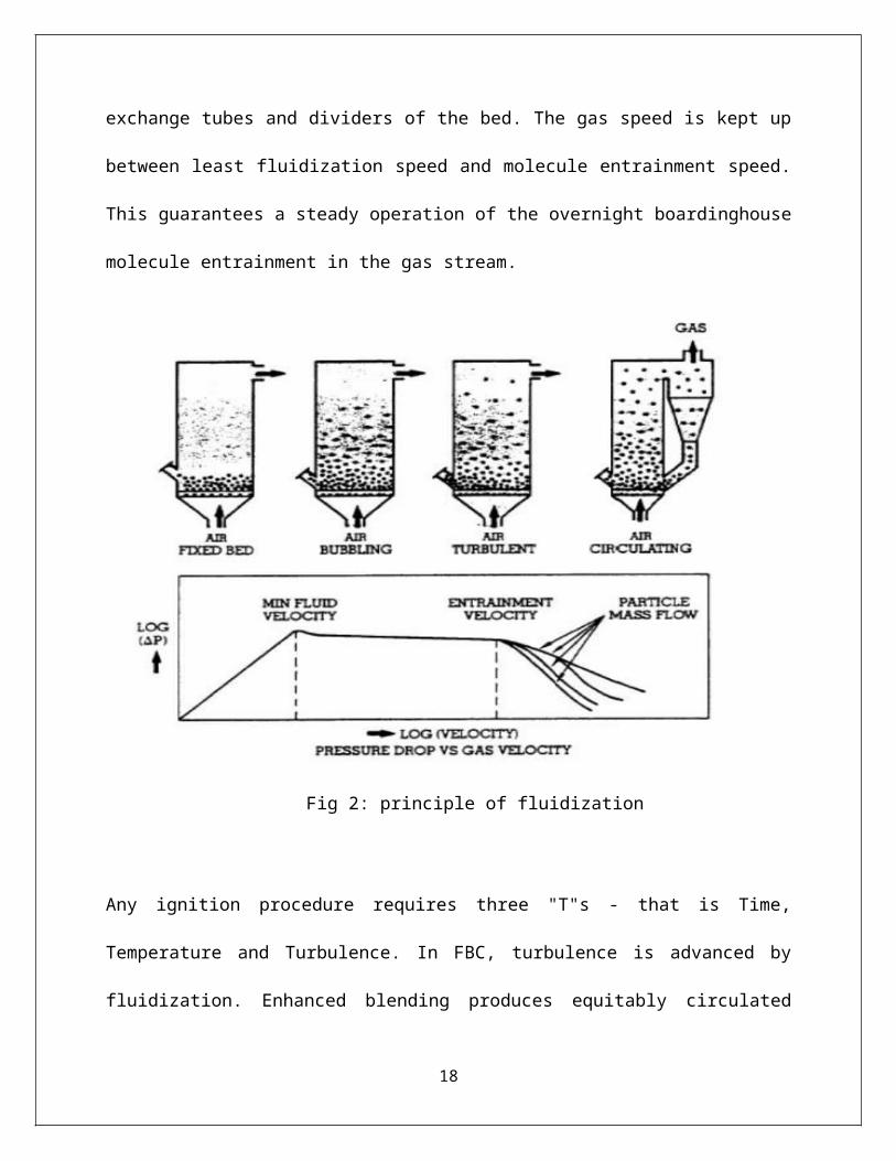
Figure 4: Bubbling Bed Boiler-1
Features of bubbling bed boiler
Fluidized bed evaporator can work at close barometrical or raised weight and have these key
components:
• Distribution plate through which air is blown for fluidizing.
• Immersed steam-raising or water warming tubes which concentrate warm specifically from the
bed
Figure 5: Bubbling Bed Boiler-2
18
The burning gasses disregard the super warmer areas of the kettle, stream past the economizer,
the dust gatherers and the air preheaters before being depleted to air. The principle uncommon
element of climatic fluidized bed burning is the requirement forced by the moderately limit
temperature range inside which the bed must be worked. With coal, there is danger of clinker
arrangement in the bed if the temperature surpasses 950 0C and loss of ignition productivity if the
temperature falls underneath 8000C. For productive sulfur maintenance, the temperature ought to
be in the scope of 800 0C to 850 0C.
a) Fuel Feeding System
For encouraging fuel and adsorbents like limestone or dolomite, normally two strategies are
taken after: under bed pneumatic sustaining and over-bed bolstering.
Under Bed Pneumatic Feeding
On the off chance that the fuel is coal, it is pounded to 1–6 mm size and pneumatically
transported from food container to the combustor through a food channel puncturing the
merchant. In view of the limit of the evaporator, the quantity of food focuses is expanded, as it is
important to appropriate the fuel into the bed consistently.
Over-Bed Feeding
The smashed coal, 6–10 mm size is passed on from coal dugout to a spreader by a screw
transport. The spreader appropriates the coal over the surface of the bed consistently. This sort of
fuel nourishing framework acknowledges over size fuel additionally and dispenses with transport
19
lines, at the point when contrasted with under-bed encouraging framework. Presently a days for
rise husk and other farming buildups over bed bolstering framework is very conspicuous and
efficient. Some of the boilers are designed to the point that they have both sorts of bolstering
frameworks.
b) Air Distributor
The motivation behind the wholesaler is to present the fluidizing air uniformly through the bed
cross segment in this manner keeping the strong particles in consistent movement, and keeping
the development of de-fluidization zones inside of the bed. The wholesaler, which frames the
heater floor ordinarily built from metal plate with various punctures in a positive geometric
design. The holes may be situated in straightforward spouts or spouts with air pocket tops, which
serve to keep strong particles from streaming once more into the space underneath the merchant.
The distributor plate is shielded from high temperature of the heater by:
Hard-headed Lining
A Static Layer of the Bed Material or
Water cooled tubes
c) Bed and In-Bed Heat Transfer Surface:
Bed
The bed material can be sand, fiery remains, smashed obstinate or limestone, with a normal size
of around 1 mm. Contingent upon the bed stature these are of two sorts: shallow quaint little inn
profound bed. At the same fluidizing speed, the two closures fluidize in an unexpected way, in
this way influencing the warmth exchange to a drenched warmth exchange surfaces. A shallow
20
bed offers a lower bed resistance and thus a lower weight drop and lower fan power utilization.
In the instance of profound bed, the weight drop is more and this expands the viable gas speed
furthermore the fan power.
In-Bed Heat Transfer Surface
In a fluidized in-bed warmth exchange process, it is important to exchange warmth between the
bed material and a submerged surface, which could be that of a tube group, or a loop. The
warmth exchanger introduction can be flat, vertical or slanted. From a weight sloping edge of
perspective, an even package in a shallow bed is more appealing than a vertical pack in a
profound bed. Additionally, the warmth move in the bed relies on upon number of parameters
like (i) bed weight (ii) bed temperature (iii) shallow gas speed (iv) Molecule size (v) Heat
exchanger configuration and (vi) gas wholesaler plate outline.
d) Ash Handling System
i) Bottom Ash Removal
In the FBC boilers, the base slag constitutes around 30 – 40 % of the aggregate powder, the rest
being the fly slag. The bed fiery remains is uprooted by constant over stream to look after bed
stature furthermore by discontinuous stream from the base to uproot over size particles, maintain
a strategic distance from collection and subsequent DE fluidization. While terminating high fiery
remains coal, for example, washery rejects, the bed fiery remains flood channel amount is
significant so uncommon consideration has to be taken.
ii) Fly Ash Removal
21
The measure of fly fiery remains to be taken care of in FBC evaporator is moderately high,
contrasted with ordinary boilers. This is because of elutriation of particles at high speeds. Fly
powder diverted by the vent gas is uprooted in number of stages; firstly in convection area, at
that point from the base of air pre-warmer/economizer lastly a noteworthy bit is uprooted in dust
authorities. The sorts of dust gatherers utilized are violent wind, pack channels, electrostatic
precipitators (ESP's) or some mix of these. To build the ignition proficiency, reusing of fly
powder is honed in a few
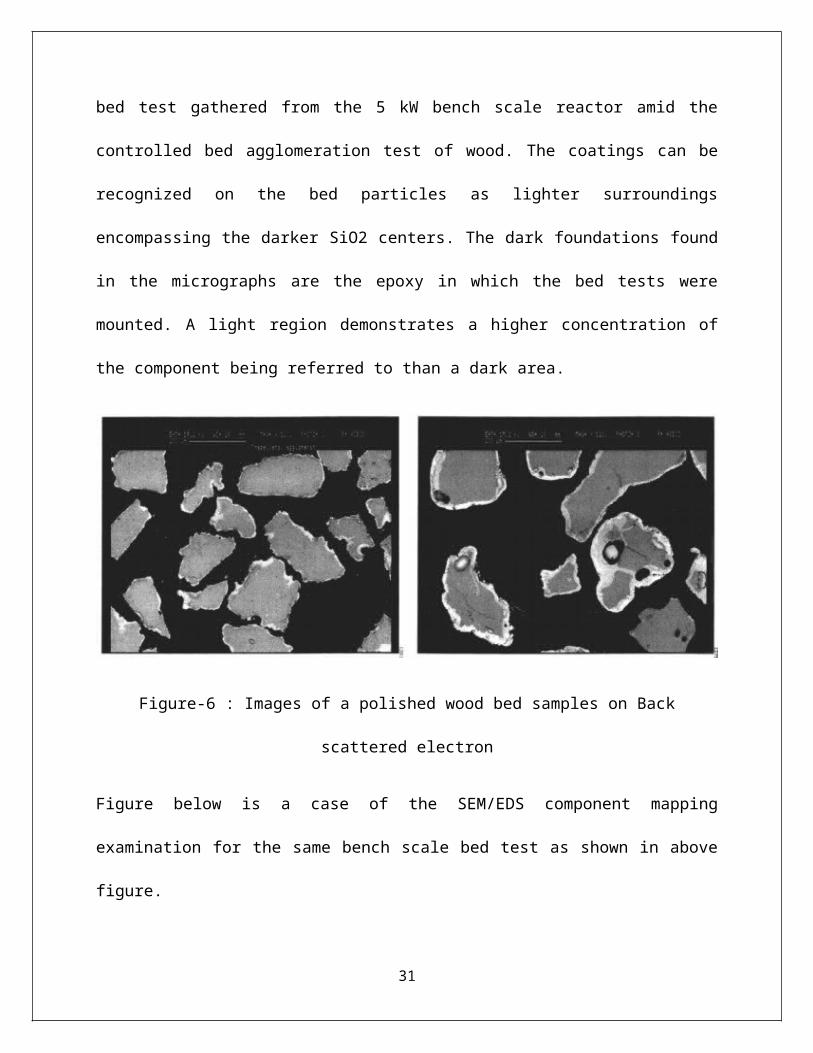
4. RESULTS AND DISCUSSIONS
The examinations of the samples by using scanning electron microscope for the bed materials
have shown that a thickness for the coating ranges from 10-50 µm was conformed to all bed
particles. A case of this coating can plainly be seen from the SEM backscatter micrographs
appeared as shown in below figure. To one side, a micrograph of a bed test from the 18 MWth
CFB boiler is appeared; to one side, a comparative picture is appeared for a bed test gathered
from the 5 kW bench scale reactor amid the controlled bed agglomeration test of wood. The
coatings can be recognized on the bed particles as lighter surroundings encompassing the darker
SiO2 centers. The dark foundations found in the micrographs are the epoxy in which the bed
tests were mounted. A light region demonstrates a higher concentration of the component being
referred to than a dark area.
22
Figure-6 : Images of a polished wood bed samples on Back scattered electron
Figure below is a case of the SEM/EDS component mapping examination for the same bench
scale bed test as shown in above figure.
23
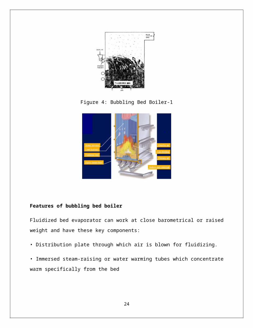
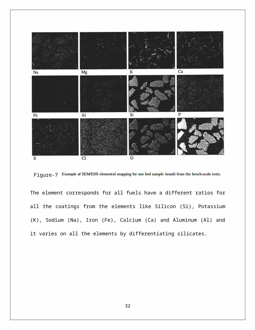
Figure-7
The element corresponds for all fuels have a different ratios for all the coatings from the
elements like Silicon (Si), Potassium (K), Sodium (Na), Iron (Fe), Calcium (Ca) and Aluminum
(Al) and it varies on all the elements by differentiating silicates.
24
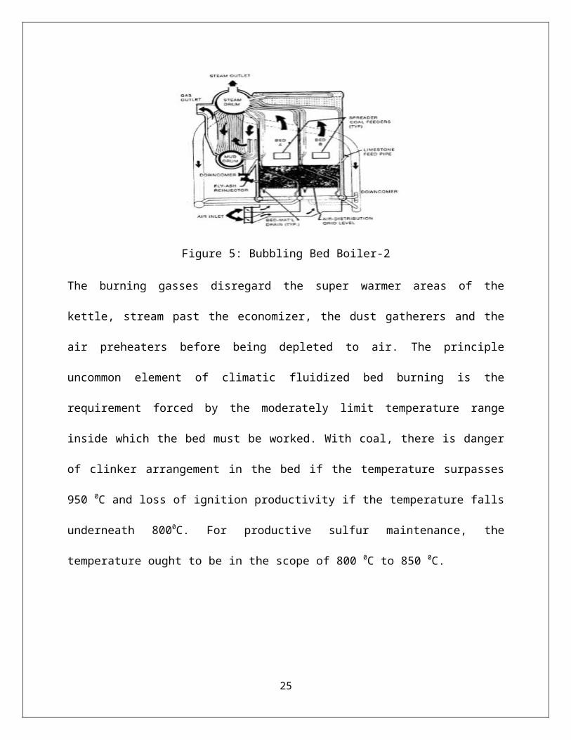
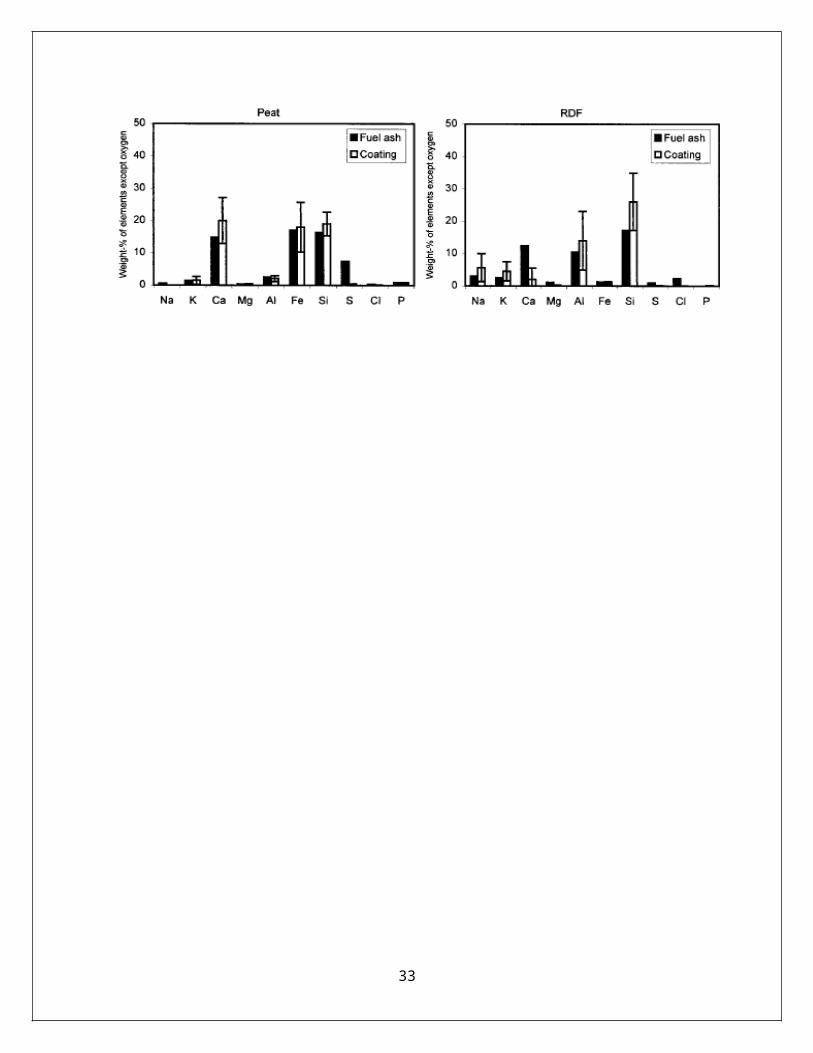
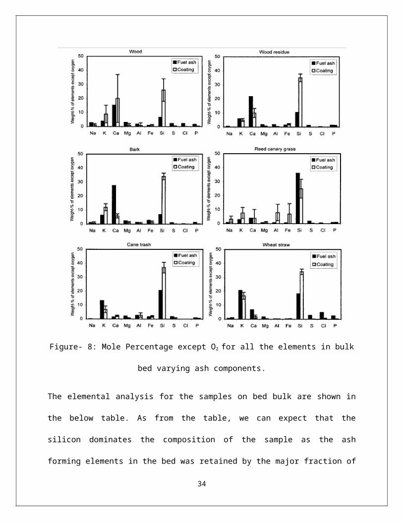
Figure- 8: Mole Percentage except O2 for all the elements in bulk bed varying ash components.
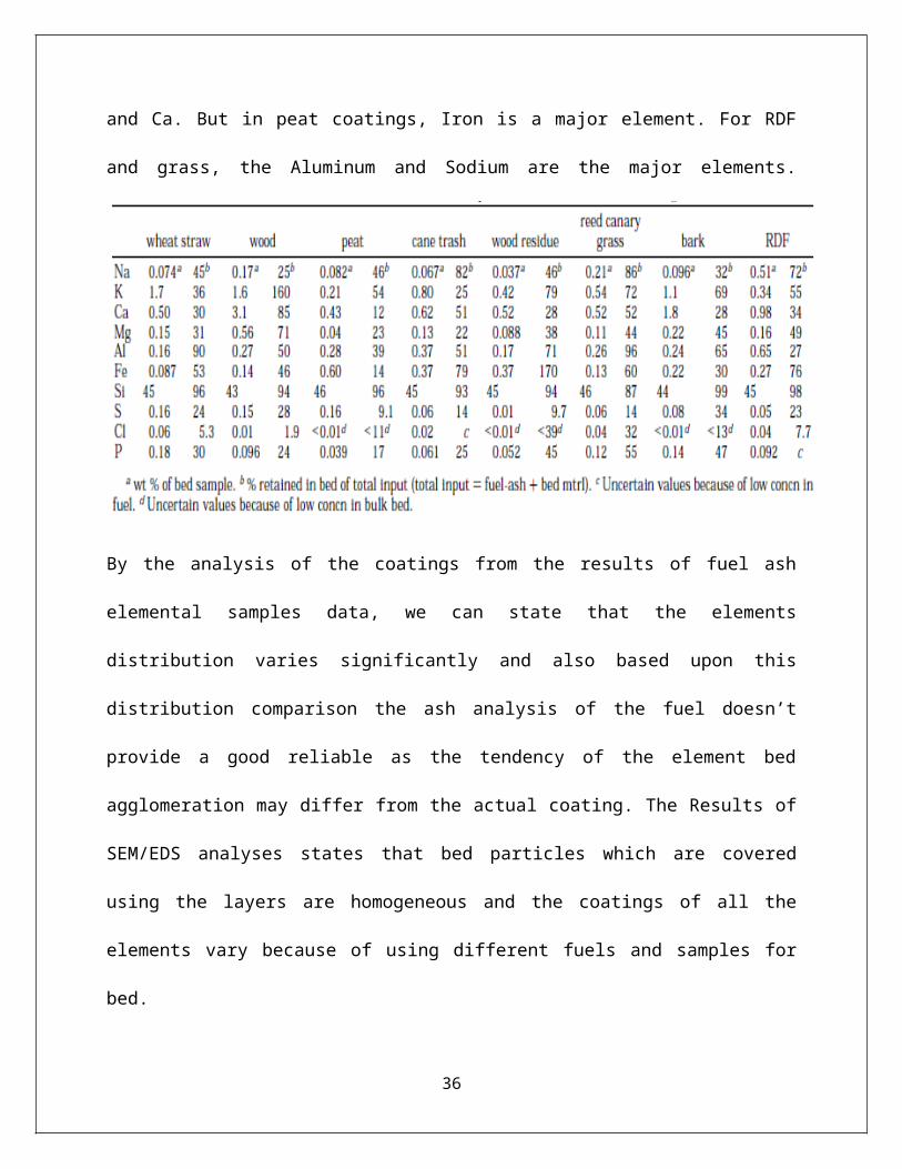
The elemental analysis for the samples on bed bulk are shown in the below table. As from the
table, we can expect that the silicon dominates the composition of the sample as the ash forming
elements in the bed was retained by the major fraction of the fuel; the part was completely
depleted by some elements in the fuel except S and Cl. The concentration of the elements in the
full scale boilers is very low, and this can be stated in the waste sludge and bark incineration
during the ash formation. In the bench scale reactor, by using the sampling and element analysis
25
we can state that the transportation and the vaporization of elements like Sulfur, Sodium,
Potassium and chlorine have transported from the bed.
This vaporization in the bench scale reactor has been increased with the increase in temperature
of the bed during the stage of combustion. And during the stage of heating phase, no vapors are
found in the external phase although the temperature has been increased to 960C. From this, we
can state that because of the characteristics of the coating, during different phases of heating also
it seem to be reliable and preserved.
From the above figure, each bar states the results of spot analysis taken from the bed particle
which has been coated. From the figure, we can state that in all cases, Silicon is the only
dominating element and rather than this Si, other elements are K and Ca. But in peat coatings,
Iron is a major element. For RDF and grass, the Aluminum and Sodium are the major elements.
By the analysis of the coatings from the results of fuel ash elemental samples data, we can state
that the elements distribution varies significantly and also based upon this distribution
comparison the ash analysis of the fuel doesn’t provide a good reliable as the tendency of the
26
element bed agglomeration may differ from the actual coating. The Results of SEM/EDS
analyses states that bed particles which are covered using the layers are homogeneous and the
coatings of all the elements vary because of using different fuels and samples for bed.
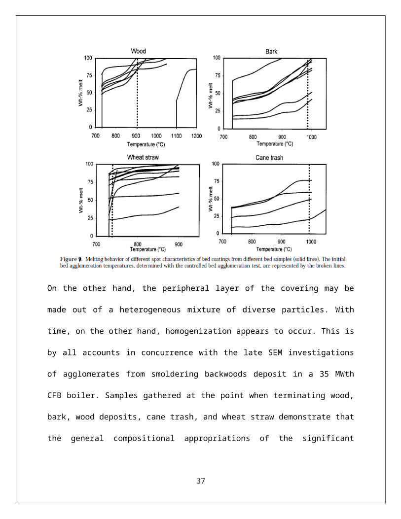
On the other hand, the peripheral layer of the covering may be made out of a heterogeneous
mixture of diverse particles. With time, on the other hand, homogenization appears to occur. This
is by all accounts in concurrence with the late SEM investigations of agglomerates from
smoldering backwoods deposit in a 35 MWth CFB boiler. Samples gathered at the point when
terminating wood, bark, wood deposits, cane trash, and wheat straw demonstrate that the general
compositional appropriations of the significant portion of the bed molecule coatings are
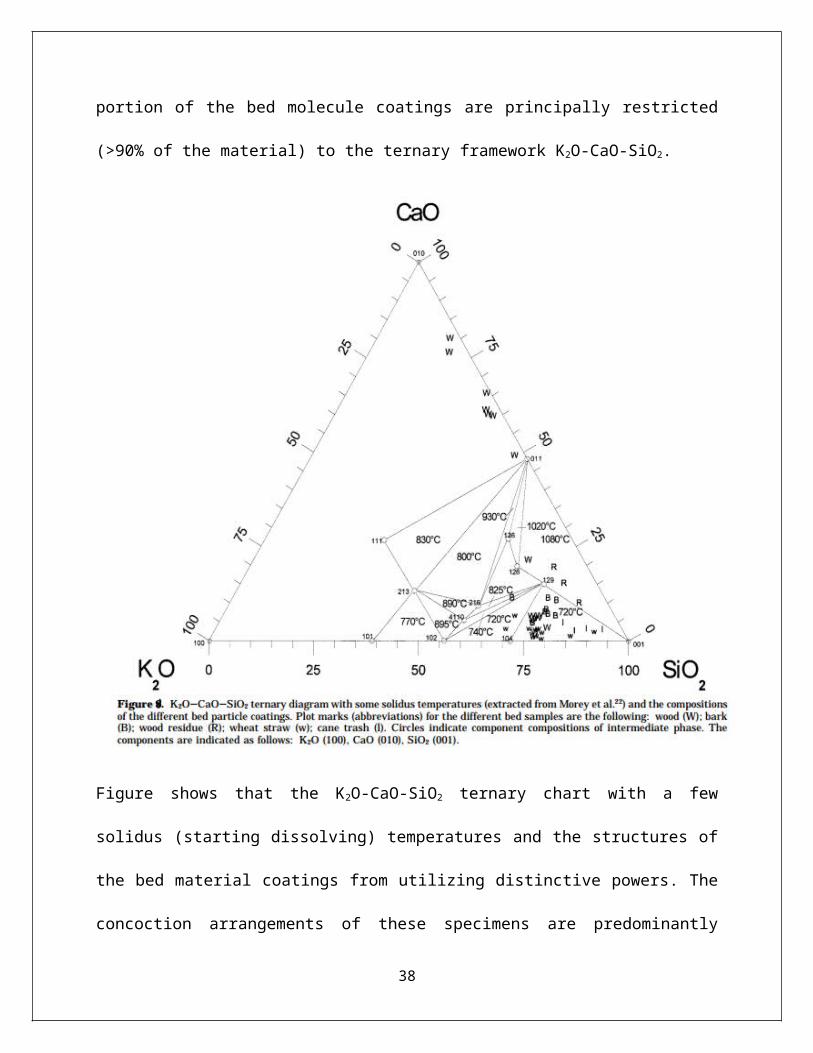
principally restricted (>90% of the material) to the ternary framework K2O-CaO-SiO2.
27
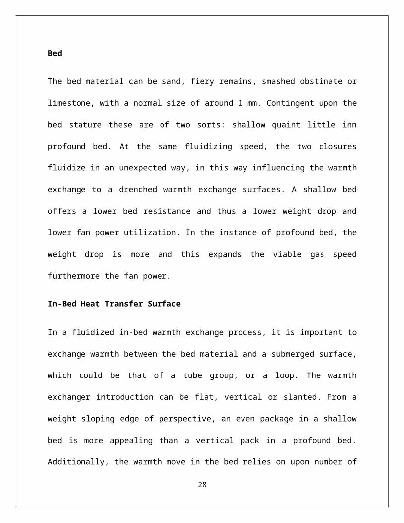
Figure shows that the K2O-CaO-SiO2 ternary chart with a few solidus (starting dissolving)
temperatures and the structures of the bed material coatings from utilizing distinctive powers.
The concoction arrangements of these specimens are predominantly limited to the SiO2 rich
corner in Figure, and silicates with these arrangements have a first dissolving temperature of 720
°C, while a little expansion of calcium will move this worth to approximately 1080 °C. Past
results have demonstrated that the concoction qualities, and along these lines the liquefying
practices of the coatings, are imperative for the bed agglomeration process. On the off chance
28
that the covering has a sufficiently high part of liquid stage, it will bring about bed
agglomeration, and, in the most serious cases, defluidization.
For silicate liquefies, the consistency of the melt must be mulled over to decide the division
required for "stickiness". It was thusly of enthusiasm to decide the liquefying practices of the
diverse bed coatings, and look at the dissolving temperatures with the relating particular
agglomeration temperatures. Attributable to an absence of thermodynamic information for a few
middle of the road stages in the framework K2O-CaO-SiO2, thermodynamic multicomponent,
and multiphase harmony estimations couldn't be utilized to precisely decide the liquefying
practices. Rather, the assessment was performed by removing dissolving conduct information
from the stage outline K2O-CaO-SiO2.
Only coatings that had natural creations (>90%) inside of the synthesis triangles in Figure 8
were incorporated into the correlation. The subsequent parts of melt (strong lines) versus
temperature are appeared in Figure 9 together with the decided beginning agglomeration
temperature (broken lines), dictated by the controlled fluidized bed agglomeration system.
29
Figure-11 : chemical sub processes for the mechanism of bed agglomeration.
The behavior at melting point is sensitive for the elements of K and Ca for the samples. Coatings
with K (high amount) and Ca (low amount) contain large content of melting temperature. And
Coatings with K (low amount) and Ca (high amount) doesn’t contains large content of melting
temperature. The agglomeration temperature follows the melting behavior when it contains high
content of melt in the coating and hence we can conclude that for the agglomeration the reason is
the melt formation.
From the chemical sub processes for the mechanism of bed agglomeration, we can state that:
1. The deposition of the ash on the material of the bed is dominated by combining smaller
particles or elements on the bed particles surfaces. By using the process of condensation
on the bed particles by using elements like Potassium chloride and Potassium Hydroxide.
30
2. As the bed particles are followed by continuous deposition then the inner layer becomes
strengthened by using sintering. The main coating characteristics like thickness are
maintained continuously for 7 to 29 hours running time.
3. The melting behavior of the layers by using the homogeneous layers is controlled by
using Adhesive forces. These forces are used to control the final temperature in the
agglomeration process.
And we can conclude that the elements which are found in the fuel are coated and this
differentiates between coatings and the bed materials. The bed particles are coated by using ash
layer which is homogeneous and the main reason for the melting is the formation of sticky layer
on the coating material of the bed causes defluidization and this may result in bed agglomeration.
The characteristics of the elements depend on the coating type which results in the melting
behavior and from results we can say that the melts (silicon) are the main reason for the process
of agglomeration.
31
5. CONCLUSIONS
In right on time organize the fluidized bed burning is observed to be the most unmistakable and
utilized for transformation of wood buildups and rural to vitality furthermore for cofiring. For the
biomass ignition which was presented around 30 years back the fluidized bed heaters are utilized
. Unmanageable materials, for example, lime stone and sand are suspended via air streams as
serve as medium for warmth for biomass fuel. High air speeds fluidize the warmth exchange
medium and biomass fuel. On the off chance that the particles stay suspended with the heater the
heater is called foaming fluidized bed. However in the event that the air speed is sufficiently high
to complete materials of the heater to be recycled, the heater is known as a circling fluidized bed.
Molecule isolation in foaming fluidized beds is basically brought about by the distinctions in
molecule densities of diverse fills. The burning temperature must be kept low around 9000C to
avert cinder sintering which could bring about DE fluidization.
For fluidized bed ignition, the fuel bed incorporates a sulfur-retaining sorbent, for example,
limestone or dolomite, which can lessen SO2 discharges by > 95%.As an outcome, fluidized bed
burning frameworks can meet most ecological models for sulfur dioxide and nitrogen dioxide,
without the requirement for post burning contamination controls.
Stuffed ignition frameworks are mesh let go heaters deprive stokers (coal is encouraged from
underneath the smoldering fuel bed). Diverse sorts of mesh heaters (up to 20 MW warm) are
accessible: settled, moving, voyaging, turning and vibrating. They are by and large not useful for
direct cofiring contrasted with fluidized bed boilers in view of the fuel property contrasts.
32
Last, pummeled fuel burning frameworks utilize pneumatically nourished fills. The biomass fuel
part may incorporate saw dust, fine shavings of woody plants, and straws. In this burning mode,
fuel amount should be kept up; the greatest fuel molecule size ought to be 10-20mm.
33
6. FUTURE WORK / DEVELOPMENTS
(http://www.processeng.biz/iea-fbc.org/upload/Developments_2005_2010.pdf)\
Amid the first half decade after the patent on fluidized bed for fuel change 1922 just a couple
gasifiers were constructed with fluidized bed. Be that as it may, fluidized bed additionally
discovered a few applications in the concoction and petroleum industry. An overall enthusiasm
for fluidized bed as a fuel converter rose in the 1970s when it was understood that fluidized bed
change offered a few ecological points of interest. This began a striking advancement in different
nations. Among different exercises, in 1980 a co-operation on the advancement of fluidized bed
burning (FBC) was started inside of the Universal Energy Agency (IEA) with support from
around ten OECD nations. Later, this action was expanded to incorporate additionally
gasification and the name was changed to fluidized bed change (FBC). Likewise, a few non-
OECD nations were welcome to take an interest. This action still goes on, in spite of the fact that
its character has changed marginally, as the information on FBC is expanding. Amid the late
years center has been on chosen issue zones, as can be seen from the productions found on the
site www.processeng.biz/iea-fbc.org/
At first, yearly reports were issued by the IEA-FBC co-operation, yet after a few years this was
found to be of restricted worth, and the yearly reports were supplanted by the site where
generally significant data about the association of the co-operation and reported results can
without much of a stretch be found. Amid the meeting in Göteborg (May 2010) a few individuals
felt that the time had come to make an outline of the status on FBC in the part nations, and the
delegates from the 16 part nations consented to make a short study on the circumstance in every
34
nation. The reason for existing is to demonstrate the conditions for FBC, which change from
nation to nation, and the late advancement in every nation, say amid the most recent five years.
Calcium Looping Cycle
(http://www.processeng.biz/iea-fbc.org/upload/Developments_2005_2010.pdf)
Improvement/testing of a flowing fluidized bed CO2 circling cycle pilot plant (for
catch/sequestration of CO2 with a reusable calcium sorbent) has been progressing. Research and
development is additionally being done on sorbent adjustment for CO2 circling cycles. Pilot-
scale work in Ottawa has now effectively exhibited CO2 circling utilizing the dual FBC test
office with more than 80% expulsion of CO2 from the carbonator and recovery accomplished
with oxy-terminating of biomass. Proceeding with pilot-scale chip away at CO2 circling
exhibition utilizing the double fluidized bed ignition test office is centered around enhancing
execution of characteristic sorbents by: molecule steady loss examinations and displaying; result
assessment under gasification union gas conditions; sorbent reactivation; heat treatment;
incomplete sulphation; and palletization. The studies are relied upon to prompt further scale-up
utilizing CanmetENERGY's 0.8 MWth flowing fluidized bed ignition facility with a scope of
Canadian feed stocks. High-pressure Combustion using FBC Technology
CanmetENERGY and its partner ThermoEnergy Corporation of the U.S.A. have developed a
multi-fuel combustion process termed HiPrOx (High Pressure Oxy-fuel). This novel high
efficiency power generating process captures CO2, along with other emissions, ready for
sequestration. The process uses high-pressure fluidized bed technology for the combustion of
fuel. Research is ongoing.
35
7. REFERENCES:
1) Technical Study Report on B IOMASS F IRED Fluidized Bed Combustion Boiler Technology
For Cogeneration.
2) Bed Agglomeration Characteristics during Fluidized Bed Combustion of Biomass Fuels by
Marcus O¨ hman and Anders Nordin Energy Technology Centre, Department of Chemistry,
Inorganic Chemistry, Umeå University, P.O. Box 726, S-941 28 Piteå, Sweden.
3) Baxter, L. L.; Miles, T. R.; Miles, T. R.; Jenkins, B. M.; Milne, T. A.; Dayton, D. C.; Bryers, R.
W.; Oden, L. L. Sandia report SAND96- 8587*UC-1301, 1996.
4) Latva-Somppi, J.; Kurkela, J.; Tapper, U.; Kauppinen, E. I.; Jokiniemi, J. K.; Johanson, B.
Proceedings of the International Conference on Ash Behavior Control in Energy Conversion
Systems, Pacifico Yokohama, Japan, 1998, pp 119-126.
5) Chemical-Looping Combustion with NiO and Fe2O3 in a Thermobalance and Circulating
Fluidized Bed Reactor with Double Loops Sung Real Son and Sang Done Kim.
6) NO and N20 Formation for Coal Combustion in a Fluidized Bed: Effect of Carbon Conversion
and Bed Temperature Claes J. Tullin,? Shakti Goel, Atsushi Morihara,z Adel F. Sarofim.
7) www.iea.org/techinitiatives/fossilfuels/fluidizedbedconversion/
8) A Comparison of Fluid-Bed Technologies for Renewable Energy Applications Authors: J.P.
DeFusco P.A. McKenzie W.R. Stirgwolt Babcock & Wilcox Power Generation Group, Inc.
Barberton, Ohio, U.S.A. Presented to: Renewable Energy World Conference Date: February 23-
25, 2010 Location: Austin, Texas, U.S.A.
9) Fluidized-Bed Combustors for Biomass Boilers September 2012 by Mark Crawford,
ASME.org.
36
10) Fluidized Bed Combustion for Clean Energy Filip Johnsson Refereed Proceedings The 12th
International Conference on Fluidization - New Horizons in Fluidization Engineering
Engineering Conferences International Year 2007.
11) Use of Fluidized Bed Technology in Solid Waste Management Doyce Tesoro-Martinez1 ,
Tomas U. Ganiron Jr2 and Harold S. Taylor3.
12) DEVELOPMENTS IN FLUIDIZED BED CONVERSION DURING 2005‐2010 A
summary from the member countries of the IEA‐FBC Implementing Agreement.
13) A Survey on Circulating Fluidized Bed Combustion Boilers Thenmozhi Ganesan 1 ,
Dr.Sivakumar Lingappan
14) Fluidized Bed Combustion As A Risk-Related Technology A Scope Of Some Potential
Problems.
15) Materials in Energy Conversion, Harvesting, and Storage By Kathy Lu.
16) Converting waste to energy through fluidised bed processing in CSIR Technology
transfer Portal.
17) W. M. Gao, L. X. Kong and P. D. Hodgson, “Numerical Simulation of Heat and Mass
Transfer in Fluidized Bed Heat Treatment Furnaces”, Journal of Materials Processing
Technology, vol. 125, (1997), pp. 170-178.
18) J. F. Davidson and D. L. Keairns, “Fluidization”, Proceedings of the Second Engineering
Foundation Conference, Trinity College, Cambridge University , (1978) April 2-6.
19) Modigell M., Traebert, A. and Weng, M. (1998), Incineration of contaminated waste in
fluidized bed with high temperature dedusting, CHISA'98, Prague, Czech Republic.
20) Verhoeff F. and Holtzer C.J.(1995), in Atmospheric Fluidized Bed Coal Combustion,
(Ed. M. Valk), Elsevier, Amsterdam, 1995, pp. 387-455.
37
21) Zevenhoven R., Yrjas P., Hupa M. (1999), in 15th Int. Conf. on Fluidized Bed
Combustion, Savannah, 16-19 Sept., USA, Paper No: Fluidised Bed Combustion 99-
0102.
22) A book on EPA Combined Heat and Power Partnership Biomass CHP Catalog.
38