Embed Size (px)
Citation preview
8/6/2019 Formwork Tie Bolts
http://slidepdf.com/reader/full/formwork-tie-bolts 1/8
FORMWORK TIESYSTEMS
8/6/2019 Formwork Tie Bolts
http://slidepdf.com/reader/full/formwork-tie-bolts 2/8
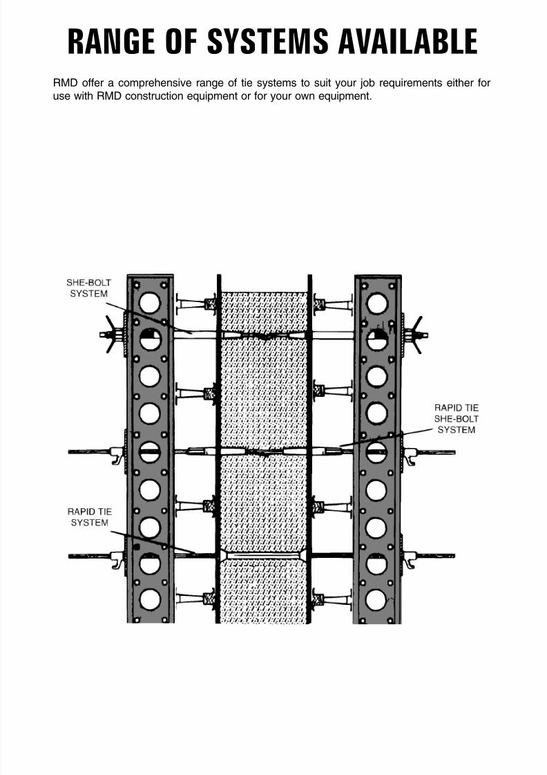
RANGE OF SYSTEMS AVAILABLERMD offer a comprehensive range of tie systems to suit your job requirements either foruse with RMD construction equipment or for your own equipment.
8/6/2019 Formwork Tie Bolts
http://slidepdf.com/reader/full/formwork-tie-bolts 3/8
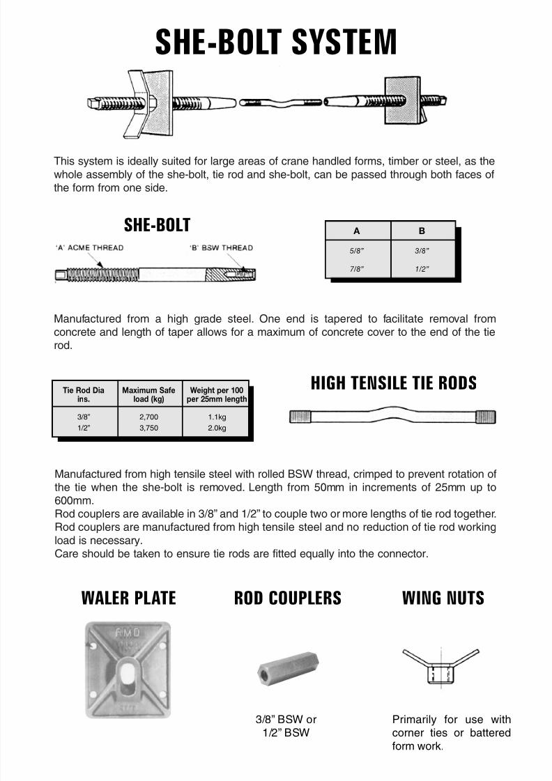
This system is ideally suited for large areas of crane handled forms, timber or steel, as the
whole assembly of the she-bolt, tie rod and she-bolt, can be passed through both faces ofthe form from one side.
Manufactured from a high grade steel. One end is tapered to facilitate removal fromconcrete and length of taper allows for a maximum of concrete cover to the end of the tierod.
Manufactured from high tensile steel with rolled BSW thread, crimped to prevent rotation ofthe tie when the she-bolt is removed. Length from 50mm in increments of 25mm up to600mm.Rod couplers are available in 3/8” and 1/2” to couple two or more lengths of tie rod together.Rod couplers are manufactured from high tensile steel and no reduction of tie rod working
load is necessary.Care should be taken to ensure tie rods are fitted equally into the connector.
SHE-BOLT SYSTEM
SHE-BOLT A B
5/8” 3/8”
7/8” 1/2”
HIGH TENSILE TIE RODSTie Rod Dia Maximum Safe Weight per 100ins. load (kg) per 25mm length
3/8” 2,700 1.1kg
1/2” 3,750 2.0kg
WALER PLATE ROD COUPLERS WING NUTS
Primarily for use withcorner ties or battered
form work.
3/8” BSW or1/2” BSW
8/6/2019 Formwork Tie Bolts
http://slidepdf.com/reader/full/formwork-tie-bolts 4/8
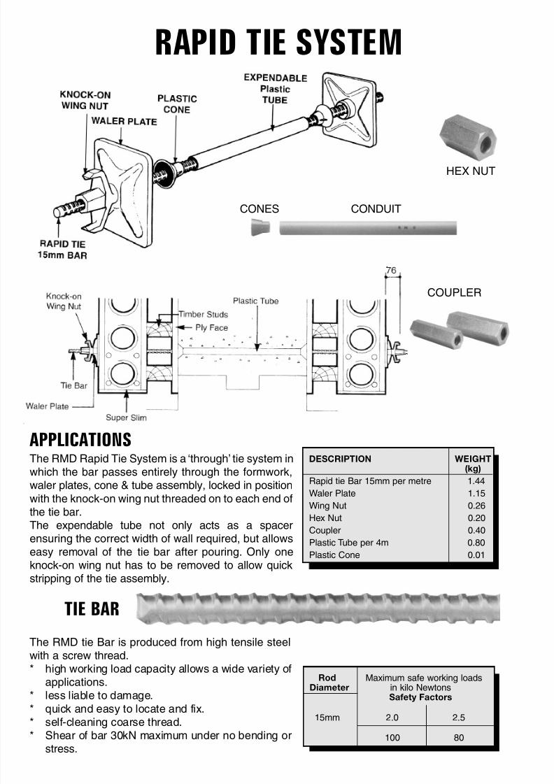
CONES CONDUIT
HEX NUT
COUPLER
The RMD Rapid Tie System is a ‘through’ tie system inwhich the bar passes entirely through the formwork,waler plates, cone & tube assembly, locked in position
with the knock-on wing nut threaded on to each end ofthe tie bar.The expendable tube not only acts as a spacerensuring the correct width of wall required, but allows
easy removal of the tie bar after pouring. Only oneknock-on wing nut has to be removed to allow quickstripping of the tie assembly.
TIE BAR
APPLICATIONS
The RMD tie Bar is produced from high tensile steelwith a screw thread.* high working load capacity allows a wide variety of
applications.* less liable to damage.
* quick and easy to locate and fix.* self-cleaning coarse thread.* Shear of bar 30kN maximum under no bending or
stress.
DESCRIPTION WEIGHT(kg)
Rapid tie Bar 15mm per metre 1.44
Waler Plate 1.15
Wing Nut 0.26
Hex Nut 0.20
Coupler 0.40
Plastic Tube per 4m 0.80
Plastic Cone 0.01
Rod Maximum safe working loads
Diameter in kilo NewtonsSafety Factors
15mm 2.0 2.5
100 80
RAPID TIE SYSTEM
8/6/2019 Formwork Tie Bolts
http://slidepdf.com/reader/full/formwork-tie-bolts 5/8
RMD RAPID ANCHOR
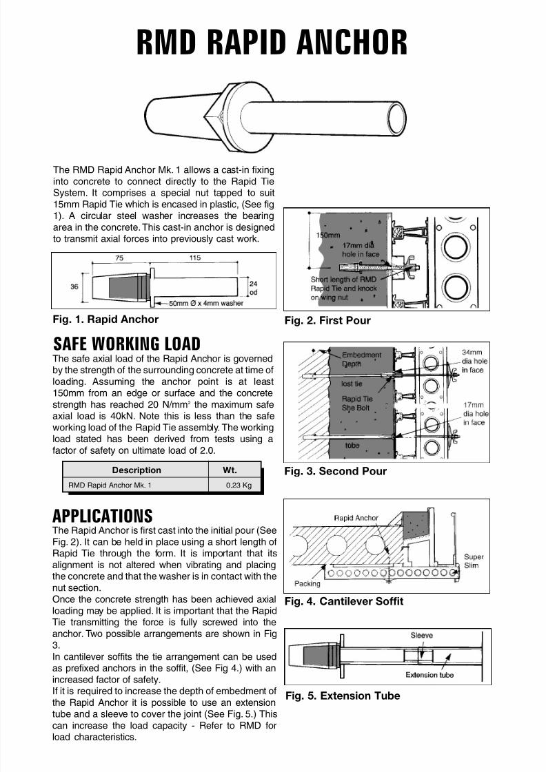
The RMD Rapid Anchor Mk. 1 allows a cast-in fixinginto concrete to connect directly to the Rapid TieSystem. It comprises a special nut tapped to suit15mm Rapid Tie which is encased in plastic, (See fig1). A circular steel washer increases the bearingarea in the concrete.This cast-in anchor is designedto transmit axial forces into previously cast work.
Fig. 2. First Pour
SAFE WORKING LOAD
Fig. 1. Rapid Anchor
The safe axial load of the Rapid Anchor is governedby the strength of the surrounding concrete at time ofloading. Assuming the anchor point is at least150mm from an edge or surface and the concrete
strength has reached 20 N/mm2
the maximum safeaxial load is 40kN. Note this is less than the safeworking load of the Rapid Tie assembly. The workingload stated has been derived from tests using afactor of safety on ultimate load of 2.0.
Fig. 3. Second PourDescription Wt.
RMD Rapid Anchor Mk. 1 0.23 Kg
APPLICATIONSThe Rapid Anchor is first cast into the initial pour (See
Fig. 2). It can be held in place using a short length ofRapid Tie through the form. It is important that itsalignment is not altered when vibrating and placingthe concrete and that the washer is in contact with thenut section.Once the concrete strength has been achieved axialloading may be applied. It is important that the RapidTie transmitting the force is fully screwed into theanchor. Two possible arrangements are shown in Fig3.In cantilever soffits the tie arrangement can be usedas prefixed anchors in the soffit, (See Fig 4.) with an
increased factor of safety.If it is required to increase the depth of embedment ofthe Rapid Anchor it is possible to use an extensiontube and a sleeve to cover the joint (See Fig. 5.) Thiscan increase the load capacity - Refer to RMD forload characteristics.
Fig. 4. Cantilever Soffit
Fig. 5. Extension Tube
8/6/2019 Formwork Tie Bolts
http://slidepdf.com/reader/full/formwork-tie-bolts 6/8
RAPID TIE SHE BOLT
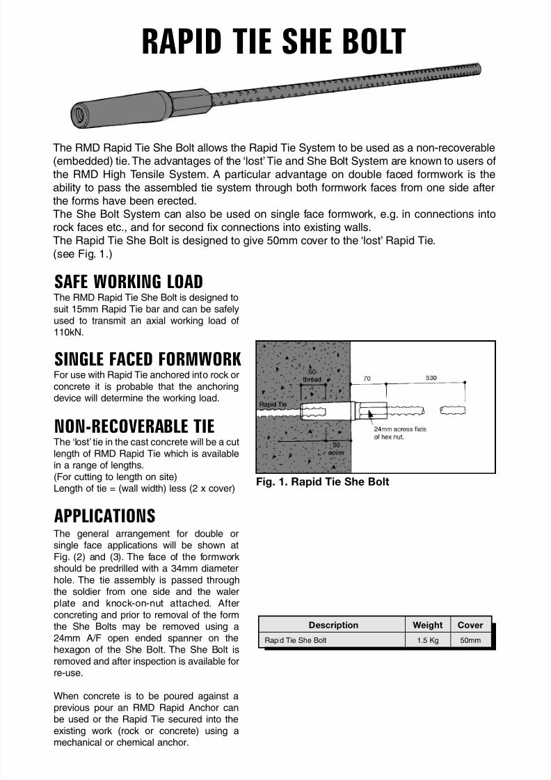
The RMD Rapid Tie She Bolt allows the Rapid Tie System to be used as a non-recoverable(embedded) tie.The advantages of the ‘lost’Tie and She Bolt System are known to users of
the RMD High Tensile System. A particular advantage on double faced formwork is theability to pass the assembled tie system through both formwork faces from one side afterthe forms have been erected.The She Bolt System can also be used on single face formwork, e.g. in connections intorock faces etc., and for second fix connections into existing walls.The Rapid Tie She Bolt is designed to give 50mm cover to the ‘lost’ Rapid Tie.
(see Fig. 1.)
SAFE WORKING LOADThe RMD Rapid Tie She Bolt is designed tosuit 15mm Rapid Tie bar and can be safelyused to transmit an axial working load of110kN.
SINGLE FACED FORMWORKFor use with Rapid Tie anchored into rock orconcrete it is probable that the anchoringdevice will determine the working load.
NON-RECOVERABLE TIEThe ‘lost’ tie in the cast concrete will be a cutlength of RMD Rapid Tie which is availablein a range of lengths.(For cutting to length on site)Length of tie = (wall width) less (2 x cover)
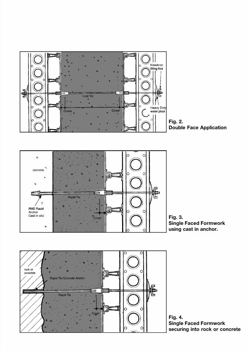
APPLICATIONSThe general arrangement for double or
single face applications will be shown atFig. (2) and (3). The face of the formworkshould be predrilled with a 34mm diameterhole. The tie assembly is passed throughthe soldier from one side and the walerplate and knock-on-nut attached. Afterconcreting and prior to removal of the formthe She Bolts may be removed using a24mm A/F open ended spanner on thehexagon of the She Bolt. The She Bolt isremoved and after inspection is available forre-use.
When concrete is to be poured against aprevious pour an RMD Rapid Anchor canbe used or the Rapid Tie secured into theexisting work (rock or concrete) using amechanical or chemical anchor.
Fig. 1. Rapid Tie She Bolt
Description Weight Cover
Rapid Tie She Bolt 1.5 Kg 50mm
8/6/2019 Formwork Tie Bolts
http://slidepdf.com/reader/full/formwork-tie-bolts 7/8
8/6/2019 Formwork Tie Bolts
http://slidepdf.com/reader/full/formwork-tie-bolts 8/8
CONCRETE ANCHOR(FOR USE WITH RMD 15MM RAPID TIE BAR)
INSTRUCTIONS FOR USE
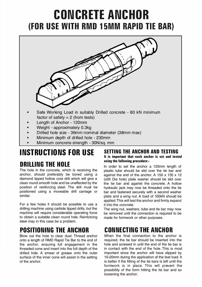
DRILLING THE HOLEThe hole in the concrete, which is receiving theanchor, should preferably be bored using adiamond tipped hollow core drill which will give aclean round smooth hole and be unaffected by theposition of reinforcing steel. The drill must bepositioned using a moveable drill carriage orsimilar.
For a few holes it should be possible to use adrilling machine using carbide tipped drills, but themachine will require considerable operating forceto obtain a suitable clean round hole. Reinforcingsteel may in this case be a problem.
POSITIONING THE ANCHORBlow out the hole to clear dust. Thread anchoronto a length of RMD Rapid Tie Bar to the end ofthe anchor, ensuring full engagement in thethreaded cone and insert into the full depth of thedrilled hole. A smear of grease onto the outersurface of the inner cone will assist in the settingof the anchor.
SETTING THE ANCHOR AND TESTINGIt is important that each anchor is set and tested
using the following procedure:-
In order to set the anchor a 120mm length ofplastic tube should be slid over the tie bar andagainst the end of the anchor. A 150 x 150 x 12(x26 Dia hole) plate washer should be slid overthe tie bar and against the concrete. A hollowhydraulic jack may now be threaded onto the tiebar and fastened securely with a second washerplate and a wing nut. A load of 100kN should be
applied.This will test the anchor and firmly expandit into the concrete.The wing nut, washers, tube and tie bar may nowbe removed until the connection is required to bemade for formwork or other purposes.
CONNECTING THE ANCHORWhen the final connection to the anchor isrequired, the tie bar should be inserted into thehole and screwed in until the end of the tie bar isin contact with the end of the hole. This is most
important since the anchor will have slipped by10-20mm during the application of the test load. Itis better if the fitting of the tie bars is left until theformwork is in place. This will prevent thepossibility of the form hitting the tie bar and soloosening the anchor.
• Safe Working Load in suitably Drilled concrete - 80 kN minimum
factor of safety = 2 (from tests)
• Length of Anchor - 120mm• Weight - approximately 0.3kg
• Drilled hole size - 36mm nominal diameter (38mm max)
• Minimum depth of drilled hole - 230mm• Minimum concrete strength - 30N/sq. mm