Embed Size (px)
Citation preview

1 IC/P6-53
FRC plasma studies on the FRX-L plasma injector for MTF G. A. Wurden 1), T. P. Intrator 1), S. Y. Zhang 1), I. G. Furno 1), S. C. Hsu 1), J. Y. Park 1), R. Kirkpatrick 1), R. M. Renneke 1), K. F. Schoenberg 1), M. J. Taccetti 1), M. G. Tuszewski 1), W. J. Waganaar 1), Zhehui Wang 1), R. E. Siemon 2), J. H. Degnan 3), D. G. Gale 3), C. Grabowski 3), E. L. Ruden 3), W. Sommars 3), M. H. Frese 4), S. Coffey 4), G. Craddock 4), S. D. Frese 4), N. F. Roderick 5) 1) Los Alamos National Laboratory, Los Alamos, United States of America 2) U of Nevada, Reno, United States of America 3) Air Force Research Laboratory, Albuquerque, United States of America 4) NumerEx, Albuquerque, NM, United States of America 5) U of New Mexico, Albuquerque, United States of America e-mail contact of main author: [email protected] Abstract. To demonstrate the physics basis for Magnetized Target Fusion (MTF), we have designed a field reversed configuration (FRC) target plasma to ultimately be compressed within an imploding metal flux conserver (liner). This new, high energy density FRC device, named FRX-L, is operating at Los Alamos as a compact “theta-pinch” formation FRC. The system capability includes a 0.5 T bias field, 70 kV 250 kHz ringing pre-ionization, and a 1.5 MA, 200 kJ main-theta-coil bank. We show FRC data with plasma parameters approaching the desired MTF requirements, examples of substantial Ohmic heating from magnetic flux annihilation, and measurements of plasma anomalous resistivity. Improvements are underway to reduce the main bank crowbar ringing, which will increase the trapped flux in the FRC. A prototype deformable flux-conserving liner with large entrance holes to accept an FRC has also been designed with MACH2 (2-D MHD modelling code) and successfully imploded at Kirtland Air Force Base on the Shiva Star pulsed power facility. 1. Introduction
Los Alamos National Laboratory leads an experimental effort to demonstrate the physics basis of Magnetized Target Fusion (MTF). MTF could be a reduced-cost path to a more attractive fusion energy system [1] that takes advantage of a plasma regime between magnetic and inertial fusion energy. Compression of a magnetized target plasma inside a flux conserving shell could heat the plasma to fusion relevant conditions. We choose to use a field reversed configuration (FRC) target plasma with high initial density (n≈1017cm-3) that is expected to increase to n>1019cm-3 after compression. Similarly, initial plasma temperatures of 100-300 eV will increase into the multi-keV regime after compression. The FRC plasma equilibrium [2] has advantages of high power density and a b ≈ 1 magnetic equilibrium, where b is the ratio of plasma particle pressure to external confining magnetic field. Flux compression is expected to amplify the FRC magnetic field from an initial 5 Tesla to a final value of ~500 Tesla. Among alternate fusion concepts, the FRC configuration for MTF would confer other advantages including:
• Small size which results in reduced total construction cost. The heart of the device sits on a table top.
• Geometric simplicity because no captured magnetic coils or center-stack Ohmic transformer are required.
• Magnetic simplicity because no toroidal magnetic field or linked magnets are required.
• Demonstrated translatability. • Particle exhaust handling that includes a natural axial divertor.

2 IC/P6-53
2. FRX-L Experiment FRX-L [3] is a Field Reversed Configuration plasma experiment at Los Alamos, designed as a compact plasma injector to study high density FRC formation, stability, and translation physics, in preparation for its eventual use to demonstrate the physics of magnetized target fusion. Figure 1 shows the FRX-L experiment in its high bay with the main capacitor bank on
the left, and cusp coil bank visible on the right. A schematic of the FRX-L FRC load region and diagnostic locations is shown in Figure 2. Diagnostics [4] include B-dot magnetic probes, external flux loops, bolometry, visible and VUV spectroscopy, an 8-chord interferometer system, end-on visible light framing cameras, twin visible-light tomography fanned arrays, and a multi-point ruby laser Thomson scattering system (still undergoing testing). 2.1. FRX-L plasma parameters Figure 3 shows the time history of plasma parameters for a nominal FRX-L shot. The FRC reaches initial equilibrium after axial contraction, at a volume average density of ~ 4×1016 cm-3 and a total temperature of ~500 eV. Then as the external magnetic field modulation occurs, the FRC first expands in size and is then compressed again. In the middle of this phase, the FRC has density of
Fig. 3. Nominal FRX-L FRC time history of two chords of electron density, total temperature from force balance, estimated internal magnetic flux, external magnetic field, volume averaged <b>, and calculated separatrix radius, for 50 mTorr static deuterium fill.
Fig. 1. FRX-L experimental bay, with main bank visible on the left and cusp bank visible on the right. The actual FRC coils are hidden to the left of the technician’s head.
Fig. 2. FRX-L formation region schematic. The theta-coil is divided into four sections to allow for diagnostic access.

3 IC/P6-53
2×1016 cm-3 and total temperature of 300 eV. The field reversed configurations presently formed in FRX-L achieve design goals for temperature, are within a factor of 2 to 3× (on the low side) in density, and possess lifetimes about half of the design goal. However, by reducing the ringing of the main bank crowbar [5] (seen on the Bz field), and raising the initial bias field, we expect to be able to achieve even better performance by maintaining higher B fields for a longer period of time and trapping more internal poloidal flux [6]. We show density chords on-axis and 0.7 cm off-axis that demonstrate an n=2 rotational instability at t=33 µsec that triggers the demise of this FRC, consistent with an oval shape spinning about the z-axis. FRC formation in FRX-L has been studied to optimize the plasma parameters and reproducibility. In order to maximize the probability of reproducible high density, long-lived FRC plasmas in FRX-L, it is crucial to minimize plasma asymmetries developed in the pre-ionization phase of the formation process. We control the timing of the main bank reversed field initiation with respect to the 250 kHz ringing pre-ionization field to provide an effective method in optimizing FRC formation. At 50 mTorr deuterium static fill pressure, FRX-L has a narrow operation window which allows reproducible FRC plasmas as shown in Figure 3. Further efforts to improve FRC parameters and confinement are being carried out [7].
2.2. Flux Annihilation In an FRC, the toroidal current (related to internal flux) decays in time as it Ohmically heats the plasma. Resistive-like diffusion relates the poloidal flux annihilation time scale to the current density at the O point magnetic axis of the toroidal current and poloidal field. Closed flux contours converge radially inward as flux annihilates. The total flux is a global quantity and measurements from the outside can be used to estimate the decay time scale for internal flux annihilation at the field null. Figure 4a shows two bounding estimates of the poloidal flux decay time (red and green curves), at τpol ~ 6-8 µsec. We assume flux dissipation can be described with anomalous resistivity η* and Ohm’s Law Eθ = η*Jθ + vr×Bz, and that flow vanishes at the O point. Radial density from our multi-chord interferometer allows estimates of the beta profile, and thus the resistivity at the O point can be inferred [8]. Spectroscopy indicates that carefully formed high density FRX-L deuterium plasmas are fairly clean but have trace amounts of silicon and oxygen coming from the quartz vacuum vessel walls. Assuming Zeff≈1, we infer an anomalously large resistivity as the FRC evolves in time, as shown in Figure 4b (black line). The inferred resistivity exceeds the Spitzer value (red line) by at least an order of magnitude. Fig 5. FRC trapped flux as a fraction of lift off
flux plotted against scaling rule, which favors large vacuum vessel size and scales weakly with density.
Fig 4. Exponential flux decay estimate (a), along with calculated resistivity (b) using Abel inverted data from the interferometer chords.
4 IC/P6-53
2.2. Scaling behaviour of high density FRC Since high density FRXL plasmas are very collisional [8], there is a concern as to whether the usual FRC scaling laws can be used to predict performance for our operation regime. We will need to trap sufficient flux during formation, so it can be dissipated during subsequent ohmic heating. Figure 5 shows a synopsis of FRC flux retention after formation. Trapped flux fraction fφ is the equilibrium flux normalized to the lift off flux, plotted for typical FRX-L shots along with past FRC machines. This scaling favors large vacuum vessel sizes, and scales weakly with density or fill pressure. FRX-L high density data is consistent with the conventional scaling.
The expected scaling of FRC heating is shown in Figure 6. Here the total temperature T=<Te+Ti> is normalized to the implosion temperature TI expected from radial shock heating (at zero lift off flux) during formation. The horizontal axis is in units of GLO, which is the ratio of lift off flux to Green Newton [2] flux. Operation at large GLO enables us to dissipate trapped flux and therefore Ohmically heat the high density FRC. In our present data, the residual ringing in the main bank field affects plasma parameters and can modulate them in a detrimental way. We are presently installing an improved crowbar switch with reduced inductance to substantially reduce this effect.
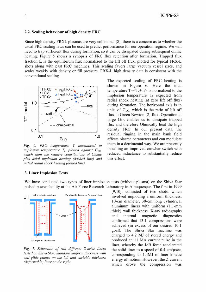
3. Liner Implosion Tests We have conducted two types of liner implosion tests (without plasma) on the Shiva Star pulsed power facility at the Air Force Research Laboratory in Albuquerque. The first in 1999
[9,10], consisted of two shots, which involved imploding a uniform thickness, 10-cm diameter, 30-cm long cylindrical aluminum liners with uniform (1.1-mm thick) wall thickness. X-ray radiographs and internal magnetic diagnostics confirmed that 13:1 compressions were achieved (in excess of our desired 10:1 goal). The Shiva Star machine was charged to 4.2 MJ of stored energy and produced an 11 MA current pulse in the liner, whereby the J×B force accelerated the solid liner to a speed of 0.4 cm/µsec, corresponding to 1.4MJ of liner kinetic energy of motion. However, the Z-current which drove the compression was
Fig. 6. FRC temperature T normalized to implosion temperature TI, plotted against GLO, which sums the relative contributions of Ohmic plus axial implosion heating (dashed line) and initial radial shock heating (dotted line).
Fig. 7. Schematic of two different Z-drive liners tested on Shiva Star. Standard uniform thickness with end glide planes on the left and variable thickness (deformable) liner on the right.

5 IC/P6-53
delivered to the liner using massive, fixed “glide-plane” end pieces with small end holes. Practical FRC injection would require a larger diameter aperture in the end electrodes. 3.1. Deformable Liner Experiment
In late 2003 we tested a a Z-pinch driven (12.5 MA, 10 µsec rise time current pulse) deformable liner, with variable thickness wall, which did not require a glide plane, and accommodated an 8-cm diameter entrance hole. This was a double frustum (using truncated conical sections to achieve the shaping), solid aluminium liner prototype. It was 30 cm long, with 9.78 cm inner diameter for its full length, 10.0 cm outer diameter for the central 18 cm of its length; while the outer diameter increased linearly to 10.2 cm at 1 cm from either electrode, and to 11 cm at the electrode contacts. Simulations were carried out of the liner implosion with the 2D MACH2 code[11]. Flash X-ray radiography (shown in Figure 8) indicated that this varying thickness results in a deforming, nearly non-sliding liner-electrode contact. A compression ratio of ~17× in the mid-section (before an m=0 sausage deformation occurred) was achieved. For comparison, our MTF design assumes that we can achieve a 10× cylindrical
compression. In Figure 9, MACH2 code modelling of the actual double frustum (double-conical) liner is
(a)
(b)
Fig. 8. (a) Static x-ray radiograph, showing bottom portion of the aluminium liner adjacent to electrode prior to implosion, and (b) Dynamic radiograph of deformed liner and bottom contact at t=22 µsec, approximately 0.5 µsec prior to peak compression, with a 2D-MHD simulation overlay.
Fig. 9. MACH2 modelling of liner thickness versus spatial position, comparing compression of the actual double frustum shaped liner (b), with a hypothetical smoothly transitioning (c) liner configuration. An enlargement (white dotted box) of the initial shape difference is shown in (a).
6 IC/P6-53
compared with modelling of a smoothly transitioning liner. The “double frustum” and “smooth” liner differ the most at ~ 2 cm upwards in the z-direction, seen in the enlarged region in the left-hand Figure 9(a), and also at 6.5 cm up along the z-direction, where the cone merges with a long straight section. The middle plot Figure 9(b) is the simulation for the imploded double frustum liner ~ 1 µsec before peak compression. The right hand plot Figure 9(c) is the same but with a liner that has a smooth initial profile. A smoothly transitioning liner is clearly more desirable, but also more difficult to fabricate. 4. Summary The FRX-L experiment at Los Alamos is now producing high density FRC target plasmas that are suitable to be tested first in a translation experiment, and then in combined imploding liner onto plasma experiments. The lifetime and energy of the FRC plasma needs to be increased by raising the bias field and reducing crowbar ringing. The performance of deformable aluminium liners driven by Shiva Star at AFRL has been benchmarked without plasma inside. These designs have sufficiently large entrance apertures to allow translated FRC plasma entry. In the actual implosion experiment, we will time the start of the FRC after initiation of the liner compression, because the present initial FRC lifetime is about half of the liner compression time (20-25 µsec). Designs for FRC translation experiments into an aluminium-walled “fake” liner are in progress for the coming year at Los Alamos. Preparations for performing the integrated plasma/liner experiment have also begun at AFRL, with expected tests commencing in about 2 years time. References: [1] R. E. Siemon, I. R. Lindemuth and K. F. Schoenberg, "Why MTF is a Low Cost Path to
Fusion", Comments Plasma Phys. Controlled Fusion, 18(6), 363 (1999). [2] M. Tuszewski, “Field Reversed Configurations”, Nuc. Fus. 28(11), 2033-2092 (1988). [3] J. M. Taccetti, T. P. Intrator, G. A. Wurden, S. Y. Zhang, R. Aragonez, P. N. Assmus,
C. M. Bass, C. Carey, S. A. deVries, W. J. Fienup, I. Furno, S. C. Hsu, M. P. Kozar, M. C. Langner, J. Liang, R. J. Maqueda, R. A. Martinez, P. G. Sanchez, K. F. Schoenberg, K. J. Scott, R. E. Siemon, E. M. Tejero, E. H. Trask, M. Tuszewski, W. J. Waganaar, C. Grabowski, E. L. Ruden, J. H. Degnan, T. Cavazos, D. G. Gale, and W. Sommars, “FRX-L: A Field Reversed Configuration Plasma Injector for Magnetized Target Fusion”. Rev. Sci. Instruments, 74(10), 4314 (2003).
[4] G. A. Wurden, T. P. Intrator, D. A. Clark, S. K. Coffey, J. H. Degnan, R. J. Maqueda, E. L. Ruden, J. M. Taccetti, F. J. Wysocki, "Diagnostics for a Magnetized Target Fusion Experiment”. Rev. Sci. Instr., 72(1), 552 (2001)
[5] Chris Grabowski, James H. Degnan, T. Cavazos Donald G. Gale, C. Gilman, W. Sommars,Tom P. Intrator, J. Martin Taccetti, B. Waganaar, R. E. Siemon, Glen A. Wurden, "Development of a High-Current Low-Inductance Crowbar Switch for FRX-L". IEEE Trans. on Plasma Science, 30(5) 1905 (2002).
[6] T. P. Intrator, Jaeyoung Park, James H. Degnan, I. Furno, Chris Grabowski, S. C. Hsu, Edward L. Ruden, P. G. Sanchez, J. Martin Taccetti, M. Tuszewski, W. J. Waganaar, Glen A. Wurden, Shouyin Y. Zhang, and Zhehui Wang, "A High-Density Field Reversed Configuration Plasma for Magnetized Target Fusion", IEEE Trans. on Plasma Science, 32(1), 152 (2004).
[7] S. Y. Zhang, G. A. Wurden, T. P. Intrator, W. J. Waganaar, R. Renneke, J. M. Taccetti, I. Furno, S. C. Hsu, E. M. Tejero, C. Grabowski, E. L. Ruden, Formation of target Field-Reversed Configuration plasma for Magnetized Target Fusion in FRX-L, 2004

7 IC/P6-53
Innovative Confinement Concepts Workshop 2004, May 25–28, 2004, Madison, Wisconsin. http://plasma.physics.wisc.edu/icc2004/html/program.htm .
[8] T. Intrator, S. Y. Zhang, J. H. Degnan, I. Furno, C. Grabowski, S. C. Hsu, E. L. Ruden, P. G. Sanchez, J. M. Taccetti, M. Tuszewski, W. J. Waganaar, and G.A. Wurden, "A high density field reversed configuration (FRC) target for magnetized target fusion: First internal profile measurements of a high density FRC", Physics of Plasmas, 11(5), 2580 (2004).
[9] J. H. Degnan, J. M. Taccetti, T. Cavazos, D. Clark, S. K. Coffey, R. J. Faehl, M. H. Frese, D. Fulton, J. C. Gueits, D. Gale, T. W. Hussey, T. P. Intrator, R. C. Kirkpatrick, G. H. Kiuttu, F. M. Lehr, J. D. Letterio, I. R. Lindemuth, W. F. McCullough, R. Moses, R. E. Peterkin Jr., R. E. Reinovsky, N. F. Roderick, E. L. Ruden, J. S. Shlachter, K. F. Schoenberg, R. E. Siemon, W. Sommars, P. J. Turchi, G. A. Wurden, F. J. Wysocki, “Implosion of solid liner for compression of field reversed configuration”, IEEE Trans. on Plasma Science 29(1), 93(2001).
[10] T. Intrator, M. Taccetti, D. A. Clark, J. H. Degnan, D. Gale, S. Coffey, J. Garcia, P. Rodriguez, W. Sommars, B. Marshall, F. Wysocki, R. Siemon, R. Faehl, K. Forman, R. Bartlett, T. Cavazos, R. J. Faehl, K. Forman, M. H. Frese, D. Fulton, J. C. Gueits, T. W. Hussey, R. Kirkpatrick, G. F. Kiuttu, F. M. Lehr, J. D. Letterio, I. Lindemuth, W. McCullough, R. Moses, R. E. Peterkin, R. E. Reinovsky, N. F. Roderick, E. L. Ruden, K. F. Schoenberg, D. Scudder, J. Shlachter, G. A. Wurden, "Experimental measurements of a converging flux conserver suitable for compressing a field reversed configuration for magnetized target fusion”, Nuclear Fusion, 42, 211(2002).
[11] R. E. Peterkin, Jr., M. H. Frese, and C. R. Sovinec, "Transport of Magnetic Flux in an Arbitrary Coordinate ALE Code," J. Comp. Phys. 140, 148 (Feb. 1998)