Embed Size (px)
Citation preview
8/6/2019 Fullpaper Comm Id00733
http://slidepdf.com/reader/full/fullpaper-comm-id00733 1/6
Proceedings of the 2008 International Conference on Electrical Machines Paper ID 733
978-1-4244-1736-0/08/$25.00 ©2008 IEEE 1
A Permanent Magnet Generator for Small Scale
Wind and Water Turbines
J.R. Bumby1
, N. Stannard2
, J Dominy3
and N. McLeod3
1
School of Engineering, Durham University, Science Site, South Road, Durham, UK, DH1 3LE,2Zeph Renewable Technologies,
3Carbon Concepts, Derbyshire
E-mail: [email protected]
Abstract- This paper describes the design and development
of a 5kW, 150 rpm, air-cored, axial flux generator for use
as a direct drive generator with small wind and water
turbines. The generator uses trapezoidal shaped magnets to
obtain a greater active length than that provided by
circular magnets. The armature coils are also trapezoidal.
A prototype generator has been tested and produces up to
5000W at 150 rpm with an electrical efficiency
substantially greater than 90%. The generator performs as
predicted by the design process.
The paper also describes how the generator can be used
to control turbine speed in strong winds. This is achieved
by introducing an additional resistive dump load on the
electrical output of the generator; this stalls the turbine as
it approaches rated speed. If the dumps load is applied and
then released, the generator can be kept within its rated
power limit. A vertical axis wind turbine and axial flux
generator are modeled to examine the speed control
system. It is found that when the turbine is subjected to a
turbulent wind, the speed control mechanism performs as
expected. Practical test has verified the simulation.
I. I NTRODUCTION
The development of an air-cored axial flux generator isdescribed in [1]-[3]. Key features of this generator are itssimplicity of design and manufacture and the complete absenceof any cogging torque; a vital requirement for some verticalaxis wind turbines. This generator is shown schematically incross-section in Fig. 1 and uses two mild steel rotors with permanent magnets attached to each rotor in a N-S-N-Sarrangement with the N magnets on one rotor facing the Smagnets on the other. The armature is made up of a number of concentrated circular coils embedded in a non-magnetic, non-conducting stator. These coils can be wound either on a bobbinand mechanically fastened into the stator or they can be bondedinto holes in the stator using a suitable resin. The generator mounted on a 2.5 kW vertical axis wind turbine (VAWT)undergoing performance testing is shown in Fig. 2 [4].
The power output from this type of machine is related to theactive area of the armature [1] by the power expression:
ω π r r K B P mΔ=2ˆˆ W (1)
N
S N
S
Turbine
shaftRotor plate
Stator with
armature
bobbins Fig. 1. General configuration of the Axial Flux Generator
Fig. 2. Generator mounted on a 2.5 kW VAWT.
Equation (1) shows that the power output depends on:
• The magnetic loading B̂ - this depends on the magnetic
thickness and the gap between the magnets.
• The electric loading K ˆ - this depends on the number of conductors and the current in the active area and is ameasure of how well filled the active area is with copper and how well cooled it is. Better cooling means morecurrent and hence more torque.
• r Δ , the radial length of the active area.
• r m, the mean magnet radius
8/6/2019 Fullpaper Comm Id00733
http://slidepdf.com/reader/full/fullpaper-comm-id00733 2/6
Proceedings of the 2008 International Conference on Electrical Machines
2
When designing the generator for a particular power ratingspecifying the armature frequency sets the number of poles. If circular coils are used then the diameter of the armature coilswill be related to the diameter of the magnets i.e. it will besimilar to, but not the same. If the diameter, number of magnets and the pole pitch are set then the mean diameter of the generator is fixed. The diameter of the armature coil will be
similar to the magnet and so the length of the active area r Δ is
fixed, as shown in Fig. 3. With circular magnets it is not possible to change the number of poles and the length of theactive area independently; they are linked by the geometry of the coils such that the active length is closely related to the pole pitch.
r m
r m
r i
r i
r o
r o
Δr Δr
Fig. 3. The “active” stator area
The consequence of this is that for a large pole number thediameter of the magnets limits the length of the active area.This can result in a generator that has quite a large radius. For small, low power, wind turbines that tend to run relativelyquickly this is not a significant problem as ease of manufactureis much more important than constraining diameter (circular coils are much easier to wind than trapezoidal ones). However as power increases, speed reduces and the length of the active
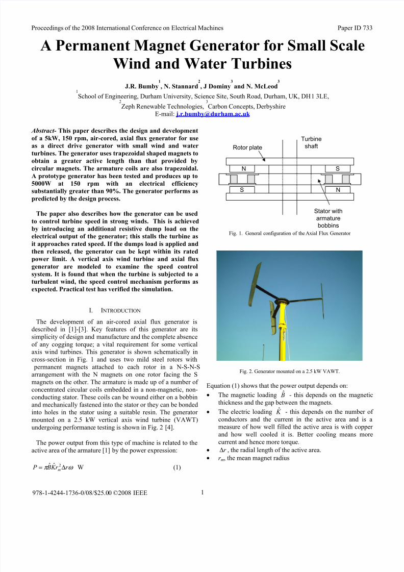
area can be small compared to the radius and limiting overalldiameter becomes more of an issue. Diameter can be reduced by using trapezoidal magnets when pole pitch and active lengthcan be decoupled for each other. The stator and rotor of such amachine are shown in Fig. 4.
(a)
(b)
Fig. 4. Rotor (a) and Stator (b) of an axial flux machine with trapezoidalmagnets
II. DESIGN PROCESS
A. Flux Density DistributionThe flux path through the generator is shown in Fig. 4.
N S N S
S N S N
Fig. 4. Flux paths
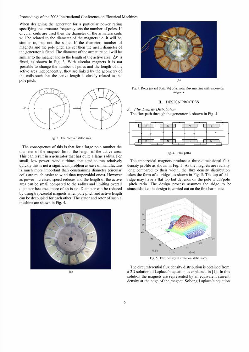
The trapezoidal magnets produce a three-dimensional fluxdensity profile as shown in Fig. 5. As the magnets are radiallylong compared to their width, the flux density distributiontakes the form of a “ridge” as shown in Fig. 5. The top of thisridge may have a flat top but depends on the pole width/pole
pitch ratio. The design process assumes the ridge to besinusoidal i.e. the design is carried out on the first harmonic.
Fig. 5. Flux density distribution at the stator
The circumferential flux density distribution is obtained froma 2D solution of Laplace’s equation as explained in [1]. In thissolution the magnets are represented by an equivalent currentdensity at the edge of the magnet. Solving Laplace’s equation
8/6/2019 Fullpaper Comm Id00733
http://slidepdf.com/reader/full/fullpaper-comm-id00733 3/6
Proceedings of the 2008 International Conference on Electrical Machines
3
then gives flux density mid-way between the magnet plates i.e.on the stator centre line by
xu B xu g
u
t u
u
J x B nnn
n
mn
n
n yn cosˆ cos
2sinh
sinhˆ)( 0
=
⎥⎥⎥⎥
⎦
⎤
⎢⎢⎢⎢
⎣
⎡
=μ
(2)
The equivalent current density is
mn
rec
remn d
u B J
2sin
4ˆ
0 μ μ τ = A/m2 (3)
whereτ
π
λ
π nnun ==
2. τ is the pole pitch, n the harmonic
number, t m is the magnet thickness, g the distance between thetwo rotor steel discs and d m is the magnet width.
B. Voltage Equation
A detailed description of the design equations for an axial-cored axial flux machine using round coil geometry can befound in [1] and [2]. A similar approach is used here tocalculate the coil dimensions, coil inductance, heat transfer
properties and rotor plate thickness.
The coil emf is calculated according to:
λ λ π ˆ44.4ˆ
2
2 f f E == (4)
Assuming the flux density is sinusoidally distributed andconsidering the first harmonic only the flux through a coil turn
of width σ cm radians is:
( )22
2sin
ˆ
iocm R R p
p
B−⎟
⎠
⎞⎜⎝
⎛ =
σ φ Wb (5)
The total flux linked by the coil can be calculated by splitting
the coil into equal three segments as shown in Fig. 6, andsumming the flux contribution of each to give:
)(3
ˆ332211 φ φ φ λ k k k
N ++= (6)
A flux reduction factor, k, has been included for each coilsegment to account for fact that the flux density falls away inthe radial direction due to leakage.
B
21σ
−
2
2σ −
2
3σ −
2
1σ +
2
2σ +
2
3σ
+
Fig. 6. Flux links across 3 segments
III. PROTOTYPE GENERATOR RESULTS
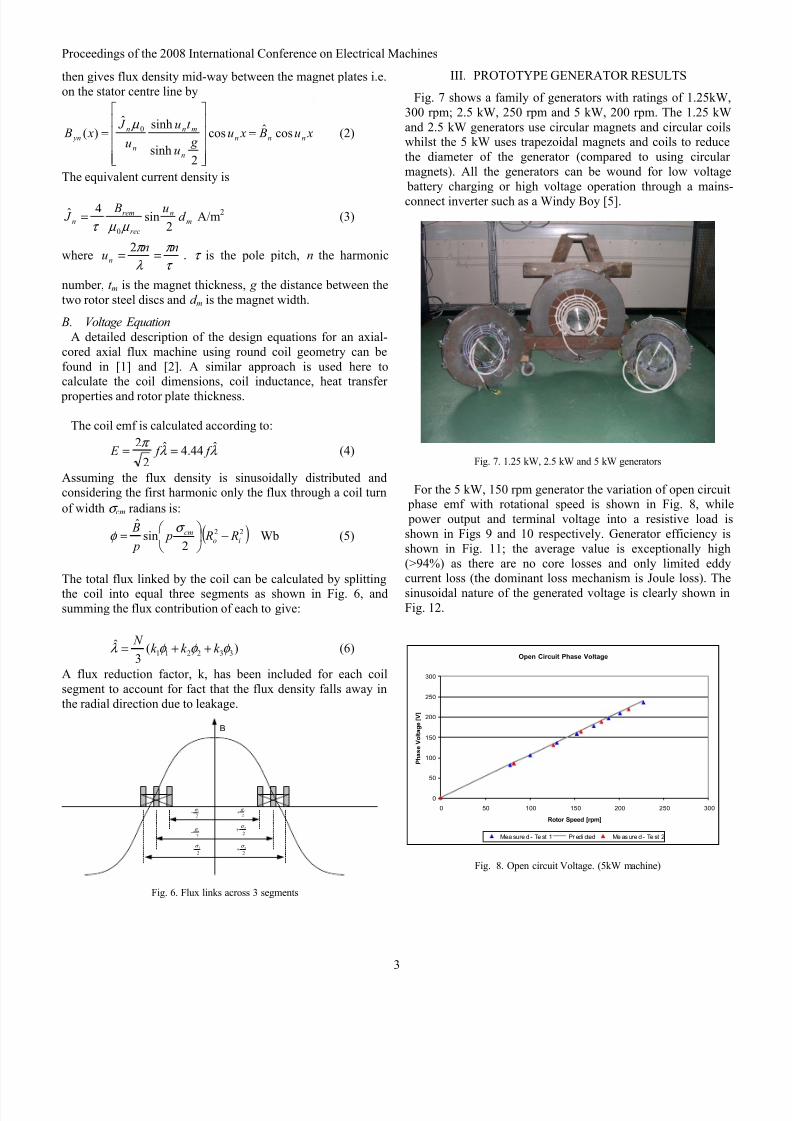
Fig. 7 shows a family of generators with ratings of 1.25kW,300 rpm; 2.5 kW, 250 rpm and 5 kW, 200 rpm. The 1.25 kWand 2.5 kW generators use circular magnets and circular coilswhilst the 5 kW uses trapezoidal magnets and coils to reducethe diameter of the generator (compared to using circular magnets). All the generators can be wound for low voltage battery charging or high voltage operation through a mains-
connect inverter such as a Windy Boy [5].
Fig. 7. 1.25 kW, 2.5 kW and 5 kW generators
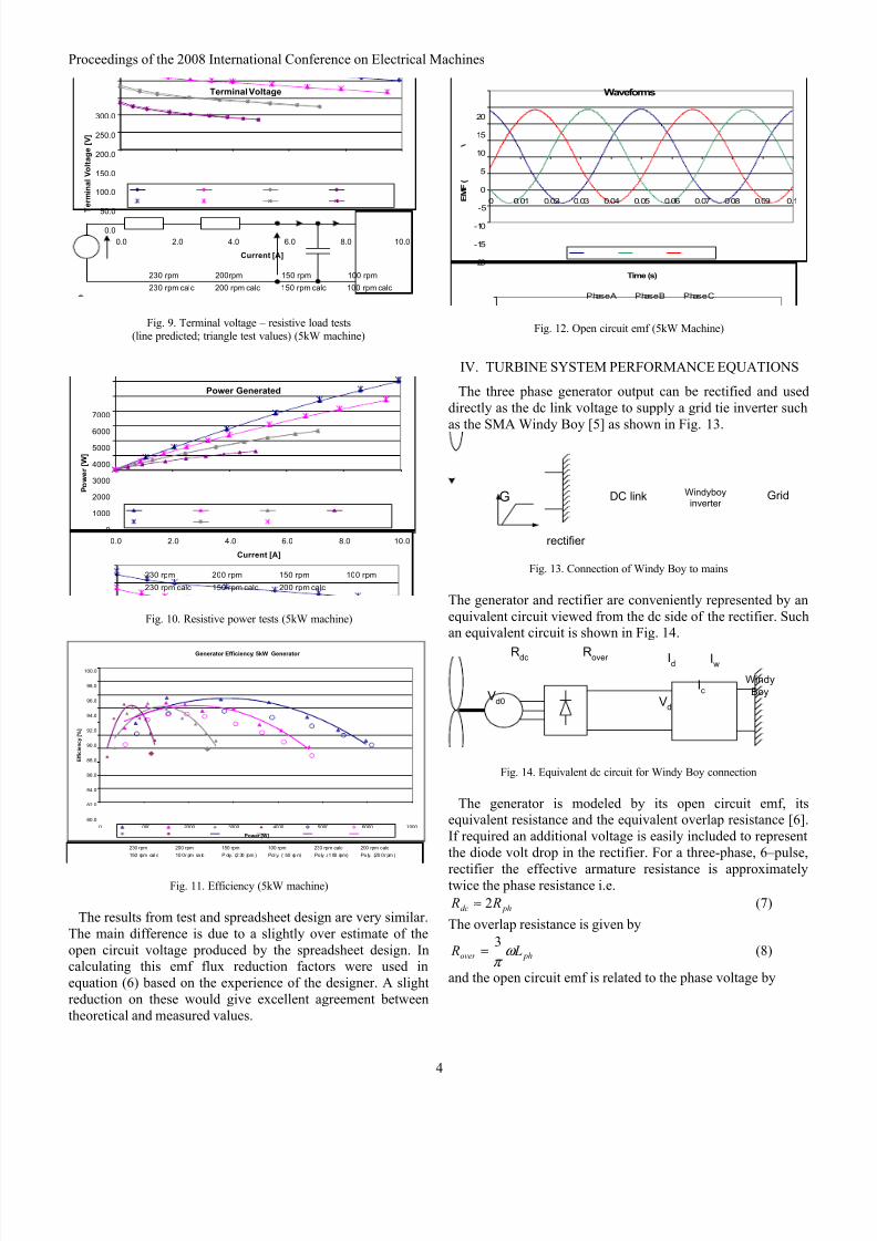
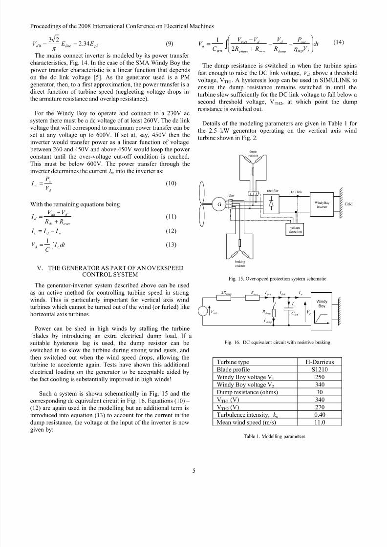
For the 5 kW, 150 rpm generator the variation of open circuit phase emf with rotational speed is shown in Fig. 8, while power output and terminal voltage into a resistive load isshown in Figs 9 and 10 respectively. Generator efficiency isshown in Fig. 11; the average value is exceptionally high(>94%) as there are no core losses and only limited eddycurrent loss (the dominant loss mechanism is Joule loss). The
sinusoidal nature of the generated voltage is clearly shown inFig. 12.
Open Circuit Phase Voltage
0
50
100
150
200
250
300
0 50 100 150 200 250 300
Rotor Speed [rpm]
P h a s e V o l t a g e [ V ]
Mea sure d - Te st 1 Pr edi cted Me as ure d - Te st 2
Fig. 8. Open circuit Voltage. (5kW machine)
8/6/2019 Fullpaper Comm Id00733
http://slidepdf.com/reader/full/fullpaper-comm-id00733 4/6
Proceedings of the 2008 International Conference on Electrical Machines
4
Terminal Voltage
0.0
50.0
100.0
150.0
200.0
250.0
300.0
0.0 2.0 4.0 6.0 8.0 10.0
Current [A]
T e r m i n a l V o l t a g e [ V ]
230 rpm 200rpm 150 rpm 100 rpm
230 rpm calc 200 rpm calc 150 rpm calc 100 rpm calc
Fig. 9. Terminal voltage – resistive load tests(line predicted; triangle test values) (5kW machine)
Power Generated
0
1000
2000
3000
4000
5000
6000
7000
0.0 2.0 4.0 6.0 8.0 10.0
Current [A]
P o w e r [ W ]
230 rpm 200 rpm 150 rpm 100 rpm
230 rpm calc 150 rpm calc 200 rpm calc
Fig. 10. Resistive power tests (5kW machine)
Generator Efficiency: 5kW Generator
80.0
82.0
84.0
86.0
88.0
90.0
92.0
94.0
96.0
98.0
100.0
0 1000 2000 3000 4000 5000 6000 7000
Power [W]
E f f i c i e n c y [ % ]
230 rpm 200 rpm 150 rpm 100 rpm 230 rpm calc 200 rpm calc
150 rpm cal c 10 0 r pm ca lc P oly. (2 30 rpm ) Pol y. (150 rp m) Po ly . (1 00 rpm) Po ly. (20 0 r pm )
Fig. 11. Efficiency (5kW machine)
The results from test and spreadsheet design are very similar.The main difference is due to a slightly over estimate of theopen circuit voltage produced by the spreadsheet design. Incalculating this emf flux reduction factors were used inequation (6) based on the experience of the designer. A slightreduction on these would give excellent agreement betweentheoretical and measured values.
Waveforms
-20
-15
-10
-5
0
5
10
15
20
0 0.01 0.02 0.03 0.04 0.05 0.06 0.07 0.08 0.09 0.1
Time (s)
E M F (
Phase A Phase B Phase C
Fig. 12. Open circuit emf (5kW Machine)
IV. TURBINE SYSTEM PERFORMANCE EQUATIONS
The three phase generator output can be rectified and useddirectly as the dc link voltage to supply a grid tie inverter suchas the SMA Windy Boy [5] as shown in Fig. 13.
G Windyboyinverter
Grid
rectifier
DC link
Fig. 13. Connection of Windy Boy to mains
The generator and rectifier are conveniently represented by anequivalent circuit viewed from the dc side of the rectifier. Suchan equivalent circuit is shown in Fig. 14.
Vd
Id
Windy
Boy
Iw
Ic
Vd0
Rover Rdc
Fig. 14. Equivalent dc circuit for Windy Boy connection
The generator is modeled by its open circuit emf, itsequivalent resistance and the equivalent overlap resistance [6].If required an additional voltage is easily included to representthe diode volt drop in the rectifier. For a three-phase, 6–pulse,
rectifier the effective armature resistance is approximatelytwice the phase resistance i.e.
phdc R R 2≈ (7)
The overlap resistance is given by
phover L R ω π
3= (8)
and the open circuit emf is related to the phase voltage by
8/6/2019 Fullpaper Comm Id00733
http://slidepdf.com/reader/full/fullpaper-comm-id00733 5/6
Proceedings of the 2008 International Conference on Electrical Machines
5
phlined E E V 34.223
0 ==π
(9)
The mains connect inverter is modeled by its power transfer characteristics, Fig. 14. In the case of the SMA Windy Boy the power transfer characteristic is a linear function that dependson the dc link voltage [5]. As the generator used is a PMgenerator, then, to a first approximation, the power transfer is adirect function of turbine speed (neglecting voltage drops inthe armature resistance and overlap resistance).
For the Windy Boy to operate and connect to a 230V acsystem there must be a dc voltage of at least 260V. The dc link voltage that will correspond to maximum power transfer can beset at any voltage up to 600V. If set at, say, 450V then theinverter would transfer power as a linear function of voltage between 260 and 450V and above 450V would keep the power constant until the over-voltage cut-off condition is reached.This must be below 600V. The power transfer through theinverter determines the current I w into the inverter as:
d
ww
V
P I = (10)
With the remaining equations being
over dc
d dod
R R
V V I
+
−= (11)
wd c I I I −= (12)
dt I C
V cd ∫ =1
(13)
V. THE GENERATOR AS PART OF AN OVERSPEED
CONTROL SYSTEM
The generator-inverter system described above can be usedas an active method for controlling turbine speed in strongwinds. This is particularly important for vertical axis windturbines which cannot be turned out of the wind (or furled) likehorizontal axis turbines.
Power can be shed in high winds by stalling the turbine blades by introducing an extra electrical dump load. If asuitable hysteresis lag is used, the dump resistor can beswitched in to slow the turbine during strong wind gusts, andthen switched out when the wind speed drops, allowing theturbine to accelerate again. Tests have shown this additionalelectrical loading on the generator to be acceptable aided bythe fact cooling is substantially improved in high winds!
Such a system is shown schematically in Fig. 15 and thecorresponding dc equivalent circuit in Fig. 16. Equations (10) – (12) are again used in the modelling but an additional term isintroduced into equation (13) to account for the current in thedump resistance, the voltage at the input of the inverter is nowgiven by:
∫ ⎟⎟
⎠
⎞
⎜⎜
⎝
⎛ −−
+
−= dt
V
P
R
V
R R
V V
C V
d WB
out
dump
d
over phase
d rect
WB
d η 2
1 (14)
The dump resistance is switched in when the turbine spinsfast enough to raise the DC link voltage, V d , above a thresholdvoltage, VTH1. A hysteresis loop can be used in SIMULINK toensure the dump resistance remains switched in until the
turbine slow sufficiently for the DC link voltage to fall below asecond threshold voltage, VTH2, at which point the dumpresistance is switched out.
Details of the modeling parameters are given in Table 1 for the 2.5 kW generator operating on the vertical axis windturbine shown in Fig. 2.
WindyBoy
inverter Grid
rectifier DC link
voltage
detection
G
relay
braking
resistor
dump
resistor
Fig. 15. Over-speed protection system schematic
over R phase R2
dump RWBC rect V
dump I
gen I link I w I
c I Windy
Boy
d V
Fig. 16. DC equivalent circuit with resistive braking
Turbine type H-Darrieus
Blade profile S1210
Windy Boy voltage V1 250
Windy Boy voltage V2 340Dump resistance (ohms) 30
VTH1 (V) 340
VTH2 (V) 270
Turbulence intensity, k σ
0.40
Mean wind speed (m/s) 11.0
Table 1. Modelling parameters
8/6/2019 Fullpaper Comm Id00733
http://slidepdf.com/reader/full/fullpaper-comm-id00733 6/6
Proceedings of the 2008 International Conference on Electrical Machines
6
Windy Boy
characteristic
4
1
2
3
Dump load
characteristic
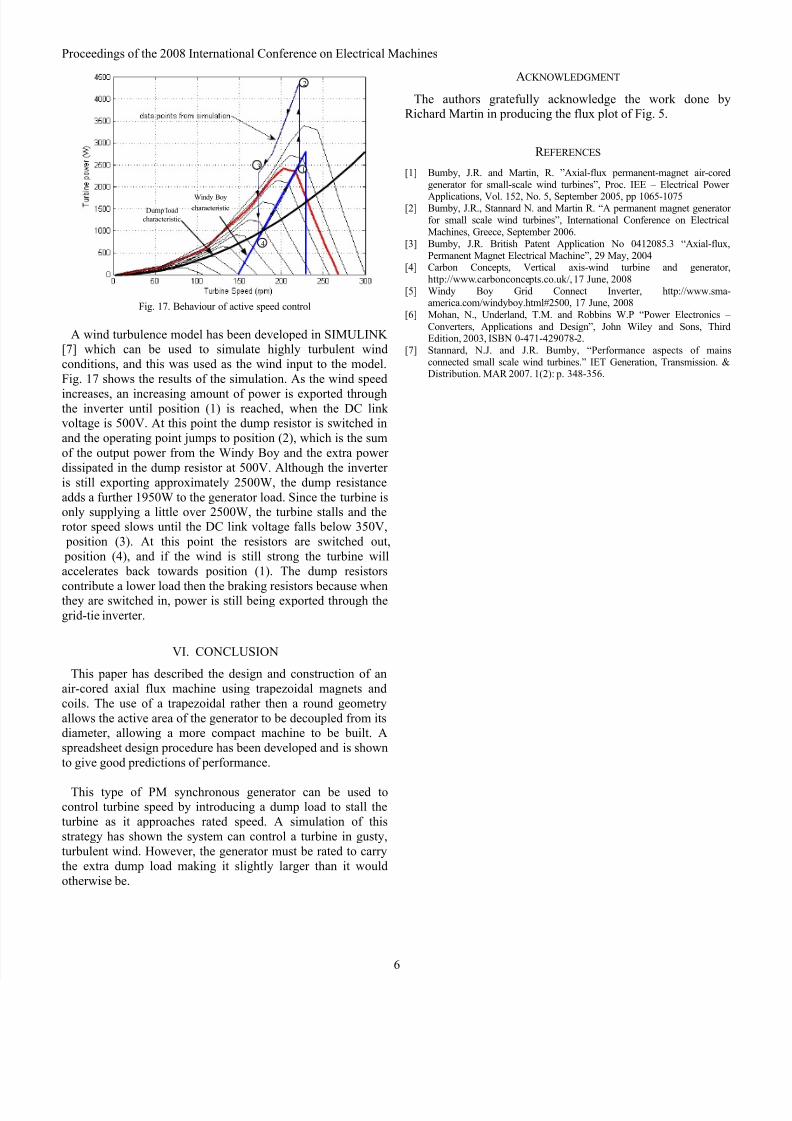
Fig. 17. Behaviour of active speed control
A wind turbulence model has been developed in SIMULINK [7] which can be used to simulate highly turbulent windconditions, and this was used as the wind input to the model.Fig. 17 shows the results of the simulation. As the wind speed
increases, an increasing amount of power is exported throughthe inverter until position (1) is reached, when the DC link voltage is 500V. At this point the dump resistor is switched inand the operating point jumps to position (2), which is the sumof the output power from the Windy Boy and the extra power dissipated in the dump resistor at 500V. Although the inverter is still exporting approximately 2500W, the dump resistanceadds a further 1950W to the generator load. Since the turbine isonly supplying a little over 2500W, the turbine stalls and therotor speed slows until the DC link voltage falls below 350V, position (3). At this point the resistors are switched out, position (4), and if the wind is still strong the turbine willaccelerates back towards position (1). The dump resistors
contribute a lower load then the braking resistors because whenthey are switched in, power is still being exported through thegrid-tie inverter.
VI. CONCLUSION
This paper has described the design and construction of anair-cored axial flux machine using trapezoidal magnets andcoils. The use of a trapezoidal rather then a round geometryallows the active area of the generator to be decoupled from itsdiameter, allowing a more compact machine to be built. Aspreadsheet design procedure has been developed and is shownto give good predictions of performance.
This type of PM synchronous generator can be used tocontrol turbine speed by introducing a dump load to stall theturbine as it approaches rated speed. A simulation of thisstrategy has shown the system can control a turbine in gusty,turbulent wind. However, the generator must be rated to carrythe extra dump load making it slightly larger than it wouldotherwise be.
ACKNOWLEDGMENT
The authors gratefully acknowledge the work done byRichard Martin in producing the flux plot of Fig. 5.
R EFERENCES
[1] Bumby, J.R. and Martin, R. ”Axial-flux permanent-magnet air-coredgenerator for small-scale wind turbines”, Proc. IEE – Electrical Power
Applications, Vol. 152, No. 5, September 2005, pp 1065-1075[2] Bumby, J.R., Stannard N. and Martin R. “A permanent magnet generator
for small scale wind turbines”, International Conference on ElectricalMachines, Greece, September 2006.
[3] Bumby, J.R. British Patent Application No 0412085.3 “Axial-flux,Permanent Magnet Electrical Machine”, 29 May, 2004
[4] Carbon Concepts, Vertical axis-wind turbine and generator,http://www.carbonconcepts.co.uk/, 17 June, 2008
[5] Windy Boy Grid Connect Inverter, http://www.sma-america.com/windyboy.html#2500, 17 June, 2008
[6] Mohan, N., Underland, T.M. and Robbins W.P “Power Electronics – Converters, Applications and Design”, John Wiley and Sons, ThirdEdition, 2003, ISBN 0-471-429078-2.
[7] Stannard, N.J. and J.R. Bumby, “Performance aspects of mainsconnected small scale wind turbines.” IET Generation, Transmission. &Distribution. MAR 2007. 1(2): p. 348-356.