Embed Size (px)
Citation preview

6/5/2015
1
http://fun3d.larc.nasa.gov
FUN3D v12.7 Training
Session 8:
Parameterization Tools
Bill Jones
FUN3D Training Workshop
June 20-21, 2015
1
http://fun3d.larc.nasa.gov
• FUN3D shape design relies on a pre-defined relationship between a set of parameters, or design variables, and the discrete surface mesh coordinates
• Given DV, surface parameterization determines Xsurf
• For example, given the current value of wing thickness at a location, what are the corresponding xyz-coordinates of the mesh?
• This narrows down the number of design variables from hundreds of thousands (raw mesh points) to dozens or hundreds• Optimizers will perform more efficiently
• Smoother design space
• An additional requirement of the parameterization package is that it provides the Jacobian of the relationship between the design variables and the surface mesh,
• While users may provide their own parameterization scheme, FUN3D is set up to handle three common packages:• MASSOUD: Aircraft-centric design variables (thickness, camber, planform,
twist, etc)
• BandAids: General FFD based tool
• Sculptor®: Commercial package from Optimal Solutions
Setting
¶Xsurf ¶DV
FUN3D Training Workshop
June 20-21, 2015
2
6/5/2015
2
http://fun3d.larc.nasa.gov
• Parameterize geometry with respect to DVs to control shape
• MASSOUD
• BandAids
• Generate perturbed surface mesh and SDs for FUN3D
design
• Visual validation
• What we will not cover
• Body transformations
• How to use the data in FUN3D
• That will be covered in the next session
Learning Goals
FUN3D Training Workshop
June 20-21, 2015
3
http://fun3d.larc.nasa.gov
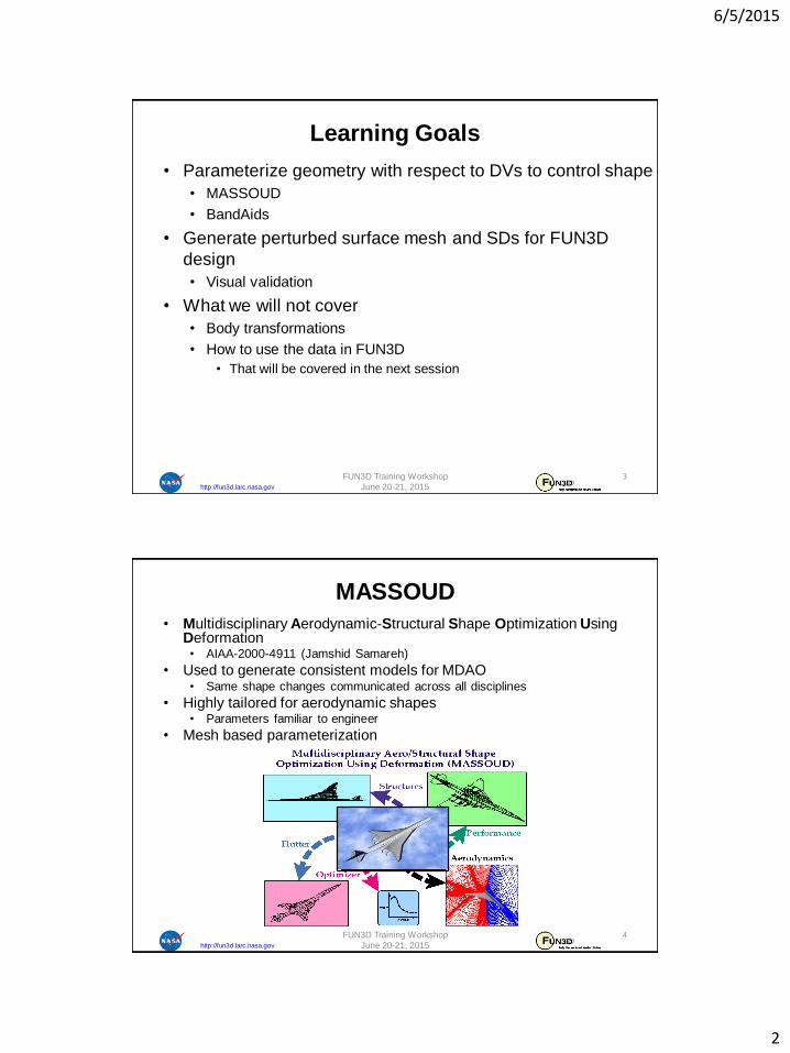
MASSOUD
• Multidisciplinary Aerodynamic-Structural Shape Optimization Using Deformation• AIAA-2000-4911 (Jamshid Samareh)
• Used to generate consistent models for MDAO• Same shape changes communicated across all disciplines
• Highly tailored for aerodynamic shapes• Parameters familiar to engineer
• Mesh based parameterization
FUN3D Training Workshop
June 20-21, 2015
4
6/5/2015
3
http://fun3d.larc.nasa.gov
• Uses soft object animation algorithms for deforming
meshes
• Nonlinear global deformation (twist and dihedral)
• NURBS surface (camber and thickness)
• Free-form deformation (planform)
• Parameterizes the discipline meshes
• Avoids mesh regeneration
• Parameterizes the changes in shape, not the shape itself
• No need to reproduce shape
• Reduces the number of design variables
MASSOUD Key Ideas
FUN3D Training Workshop
June 20-21, 2015
5
http://fun3d.larc.nasa.gov
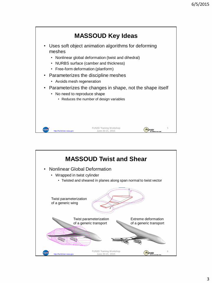
• Nonlinear Global Deformation
• Wrapped in twist cylinder
• Twisted and sheared in planes along span normal to twist vector
MASSOUD Twist and Shear
Twist parameterization of a generic wing
Twist parameterization of a generic transport
Extreme deformation of a generic transport
FUN3D Training Workshop
June 20-21, 2015
6
6/5/2015
4
http://fun3d.larc.nasa.gov
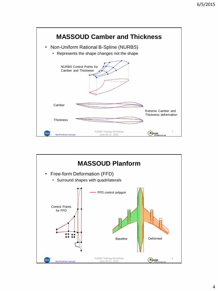
• Non-Uniform Rational B-Spline (NURBS)
• Represents the shape changes not the shape
MASSOUD Camber and Thickness
NURBS Control Points for
Camber and Thickness
Camber
Extreme Camber and
Thickness deformation
Thickness
FUN3D Training Workshop
June 20-21, 2015
7
http://fun3d.larc.nasa.gov
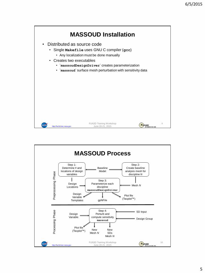
• Free-form Deformation (FFD)
• Surround shapes with quadrilaterals
MASSOUD Planform
Baseline
Control Points
for FFD
Deformed
FFD control polygon
FUN3D Training Workshop
June 20-21, 2015
8
6/5/2015
5
http://fun3d.larc.nasa.gov
• Distributed as source code
• Single Makefile uses GNU C compiler (gcc)
• Any localization must be done manually
• Creates two executables
• `massoudDesignDriver` creates parameterization
• `massoud` surface mesh perturbation with sensitivity data
MASSOUD Installation
FUN3D Training Workshop
June 20-21, 2015
9
http://fun3d.larc.nasa.gov
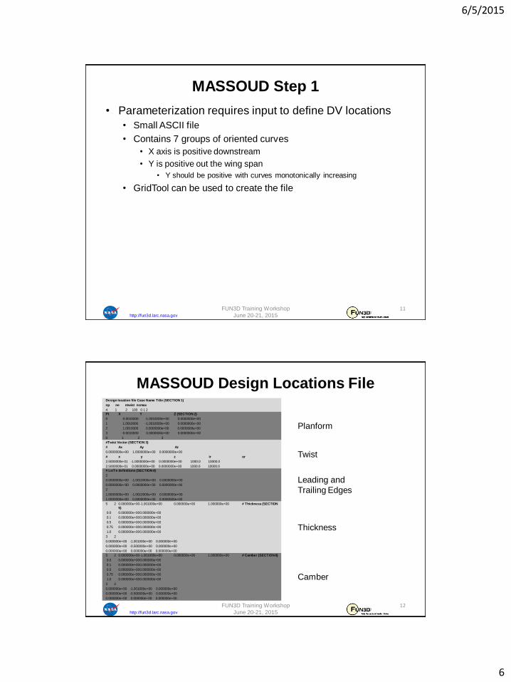
MASSOUD Process
Step 1:
Determine # and
locations of design
variables
Step 2:
Create baseline
analysis mesh for
discipline N
Step 3:
Parameterize each
disciplinemassoudDesignDriver
Step 4:
Perturb and
compute sensitivitymassoud
Baseline
Model
gpNFile
Design
Variable
Templates
Plot file
(Tecplot™)
Design
Variable
SD Input
Design Group
New
SDs
Mesh N
New
Mesh N
Plot file
(Tecplot™)
Pre
pro
cessin
g P
hase
Pro
cessin
g P
hase
Design
LocationsMesh N
FUN3D Training Workshop
June 20-21, 2015
10
6/5/2015
6
http://fun3d.larc.nasa.gov
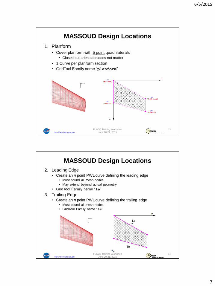
• Parameterization requires input to define DV locations
• Small ASCII file
• Contains 7 groups of oriented curves
• X axis is positive downstream
• Y is positive out the wing span
• Y should be positive with curves monotonically increasing
• GridTool can be used to create the file
MASSOUD Step 1
FUN3D Training Workshop
June 20-21, 2015
11
http://fun3d.larc.nasa.gov
Planform
MASSOUD Design Locations File
Twist
Leading and
Trailing Edges
Thickness
Camber
FUN3D Training Workshop
June 20-21, 2015
12
Design location file Case Name Title (SECTION 1)
np ne ntwist ncmax
4 1 2 100 0 1 2
Pt X Y Z (SECTION 2)
0 -0.0010000 -1.0010000e+00 0.0000000e+00
1 1.0010000 -1.0010000e+00 0.0000000e+00
2 1.0010000 0.0000000e+00 0.0000000e+00
3 -0.0010000 0.0000000e+00 0.0000000e+00
0 1 2 3
#Twist Vector (SECTION 3)
# Ax Ay Az
0.0000000e+00 1.0000000e+00 0.0000000e+00
# x y z ir or
2.5000000e-01 -1.0000000e+00 0.0000000e+00 1000.0 10000.0
2.5000000e-01 0.0000000e+00 0.0000000e+00 1000.0 10000.0
# Le/Te definitions (SECTION 4)
2
0.0000000e+00 -1.0010000e+00 0.0000000e+00
0.0000000e+00 0.0000000e+00 0.0000000e+00
2
1.0000000e+00 -1.0010000e+00 0.0000000e+00
1.0000000e+00 0.0000000e+00 0.0000000e+00
5 2 0.000000e+00-1.001000e+00 0.000000e+00 1.000000e+00 # Thickness (SECTION
5)
0.0 0.000000e+000.000000e+00
0.1 0.000000e+000.000000e+00
0.5 0.000000e+000.000000e+00
0.75 0.000000e+000.000000e+00
1.0 0.000000e+000.000000e+00
3 2
0.000000e+00 -1.001000e+00 0.000000e+00
0.000000e+00 -0.500000e+00 0.000000e+00
0.000000e+00 0.000000e+00 0.000000e+00
5 2 0.000000e+00-1.001000e+00 0.000000e+00 1.000000e+00 # Camber (SECTION 6)
0.0 0.000000e+000.000000e+00
0.1 0.000000e+000.000000e+00
0.5 0.000000e+000.000000e+00
0.75 0.000000e+000.000000e+00
1.0 0.000000e+000.000000e+00
3 2
0.000000e+00 -1.001000e+00 0.000000e+00
0.000000e+00 -0.500000e+00 0.000000e+00
0.000000e+00 0.000000e+00 0.000000e+00
6/5/2015
7
http://fun3d.larc.nasa.gov
1. Planform
• Cover planform with 5 point quadrilaterals
• Closed but orientation does not matter
• 1 Curve per planform section
• GridTool Family name “planform”
MASSOUD Design Locations
FUN3D Training Workshop
June 20-21, 2015
13
http://fun3d.larc.nasa.gov
2. Leading Edge
• Create an n point PWL curve defining the leading edge
• Must bound all mesh nodes
• May extend beyond actual geometry
• GridTool Family name “le”
3. Trailing Edge• Create an n point PWL curve defining the trailing edge
• Must bound all mesh nodes
• GridTool Family name “te”
MASSOUD Design Locations
Le
Te
FUN3D Training Workshop
June 20-21, 2015
14

6/5/2015
8
http://fun3d.larc.nasa.gov
4. Twist Vector• Create a 2 point curve to represent the twist vector
• Twist sections defined normal to this vector
• GridTool Family name “twistv”
5. Twist Location• Create an n point PWL curve to represent the n twist locations
• Airfoil sections defined at these points normal to “twistv”• First and last section must bound the Y coordinates of the target mesh
• GridTool family name “twist”
MASSOUD Design Locations
Twist
Shear
Twist Vector
Twist Vector
FUN3D Training Workshop
June 20-21, 2015
15
http://fun3d.larc.nasa.gov
• Thickness• Chordwise
• Create an n point PWL curve to represent the n chordwisethickness locations
• Start, length, and %
• GridTool family name “tx”
• Spanwise
• Create an m point PWL curve to represent the m spanwisethickness locations
• Should bound Y values of all target mesh nodes
• Beginning and ending Y coordinates must be bounded by the Y coordinates of both the “le” and “te” curves
• May be a duplicate of the “twist” curve
• GridTool family name “ty”
• n x m set of DVs
MASSOUD Design Locations
T1
T2
T3
T4
T7
T10
T13
T14
T6
T9
T12
T15
“tx”
“ty”
FUN3D Training Workshop
June 20-21, 2015
16
6/5/2015
9
http://fun3d.larc.nasa.gov
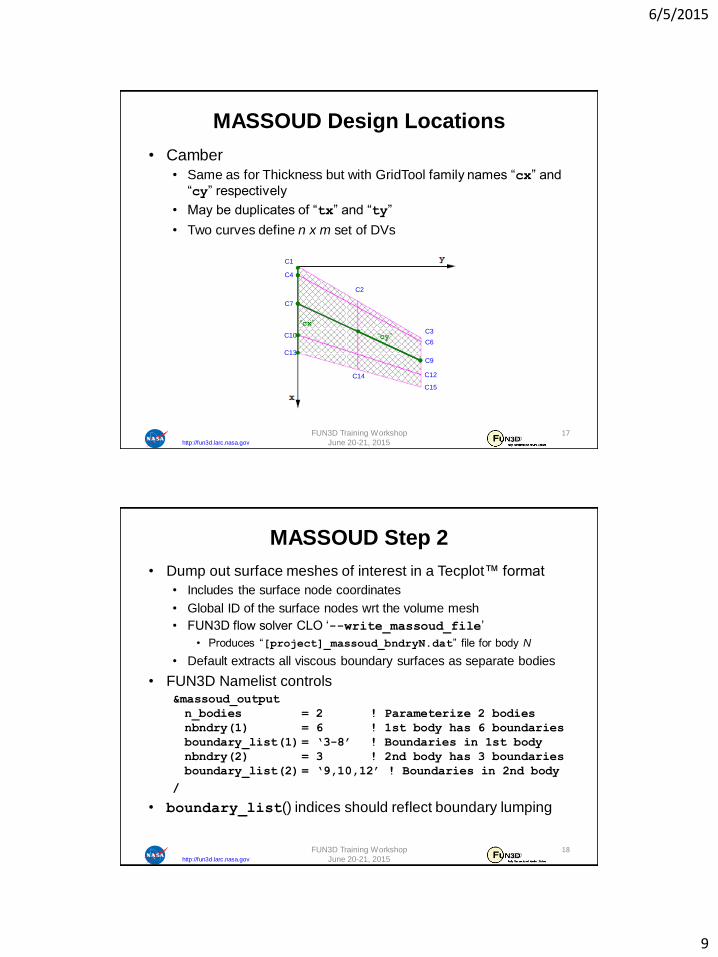
• Camber
• Same as for Thickness but with GridTool family names “cx” and
“cy” respectively
• May be duplicates of “tx” and “ty”
• Two curves define n x m set of DVs
MASSOUD Design Locations
C1
C2
C3
C4
C7
C10
C13
C14
C6
C9
C12
C15
“cx”
“cy”
FUN3D Training Workshop
June 20-21, 2015
17
http://fun3d.larc.nasa.gov
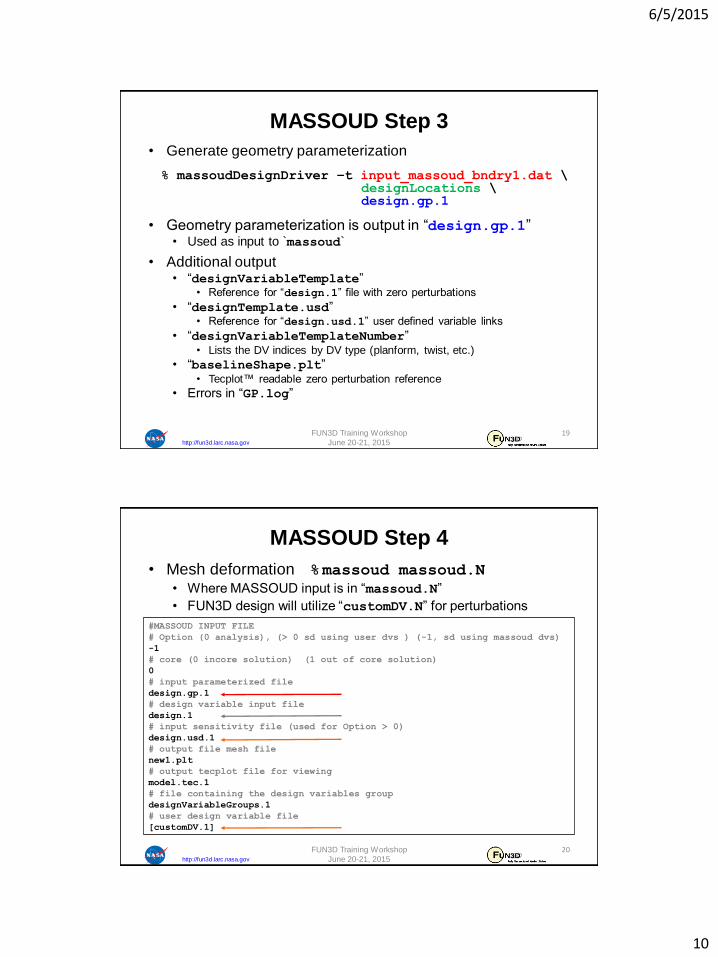
• Dump out surface meshes of interest in a Tecplot™ format
• Includes the surface node coordinates
• Global ID of the surface nodes wrt the volume mesh
• FUN3D flow solver CLO ‘--write_massoud_file’
• Produces “[project]_massoud_bndryN.dat” file for body N
• Default extracts all viscous boundary surfaces as separate bodies
• FUN3D Namelist controls&massoud_output
n_bodies = 2 ! Parameterize 2 bodies
nbndry(1) = 6 ! 1st body has 6 boundaries
boundary_list(1) = ‘3-8’ ! Boundaries in 1st body
nbndry(2) = 3 ! 2nd body has 3 boundaries
boundary_list(2) = ‘9,10,12’ ! Boundaries in 2nd body
/
• boundary_list() indices should reflect boundary lumping
MASSOUD Step 2
FUN3D Training Workshop
June 20-21, 2015
18
6/5/2015
10
http://fun3d.larc.nasa.gov
• Generate geometry parameterization
% massoudDesignDriver –t input_massoud_bndry1.dat \designLocations \design.gp.1
• Geometry parameterization is output in “design.gp.1”• Used as input to `massoud`
• Additional output• “designVariableTemplate”
• Reference for “design.1” file with zero perturbations
• “designTemplate.usd”• Reference for “design.usd.1” user defined variable links
• “designVariableTemplateNumber”• Lists the DV indices by DV type (planform, twist, etc.)
• “baselineShape.plt”• Tecplot™ readable zero perturbation reference
• Errors in “GP.log”
MASSOUD Step 3
FUN3D Training Workshop
June 20-21, 2015
19
http://fun3d.larc.nasa.gov
• Mesh deformation %massoud massoud.N
• Where MASSOUD input is in “massoud.N”
• FUN3D design will utilize “customDV.N” for perturbations
#MASSOUD INPUT FILE
# Option (0 analysis), (> 0 sd using user dvs ) (-1, sd using massoud dvs)
-1
# core (0 incore solution) (1 out of core solution)
0
# input parameterized file
design.gp.1
# design variable input file
design.1
# input sensitivity file (used for Option > 0)
design.usd.1
# output file mesh file
new1.plt
# output tecplot file for viewing
model.tec.1
# file containing the design variables group
designVariableGroups.1
# user design variable file
[customDV.1]
MASSOUD Step 4
FUN3D Training Workshop
June 20-21, 2015
20

6/5/2015
11
http://fun3d.larc.nasa.gov
• Visual inspection
• Tecplot™
• “model.tec.1.sd1” contains mesh and SDs
• (e.g. XD1, YD1, ZD1… XDndv, YDndv, ZDndv)
• GridTool
% GridTool –d model.tec.1.sd1
• Sliders to interactively perturb DVs
• Twist is non-linear and is only indication of change
MASSOUD Results
FUN3D Training Workshop
June 20-21, 2015
21
http://fun3d.larc.nasa.gov
• Failure … check “GP.log”
• Design locations must be defined to bound all target mesh nodes
What Could Go Wrong (1 of 2)
Twist Vector
Twist Vector
FUN3D Training Workshop
June 20-21, 2015
22
6/5/2015
12
http://fun3d.larc.nasa.gov
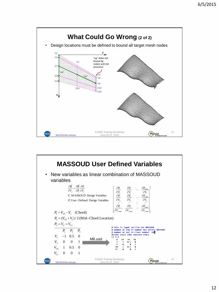
• Design locations must be defined to bound all target mesh nodes
C1
C2
C3
C4
C7
C10
C13
C14
C6
C9
C12
C15
“cx”
“cy”
“cy” does not
bound tip
nodes with full
precision
What Could Go Wrong (2 of 2)
FUN3D Training Workshop
June 20-21, 2015
23
http://fun3d.larc.nasa.gov
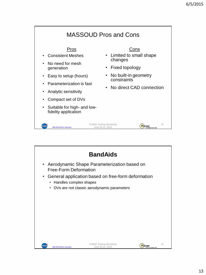
• New variables as linear combination of MASSOUD
variables
M6.usd
VariablesDesign Defined- User
VariablesDesign MASSOUD
i
j
j
i
ij
P
V
V
P
P
R
V
R
max
max
max
2
max
1
2
max
2
2
2
1
1
max
1
2
1
1
j
i
jj
i
i
V
P
V
P
V
P
V
P
V
P
V
P
V
P
V
P
V
P
100
05.01
100
05.01
Location) Chord-(Mid 2/)(
(Chord)
11
10
2
1
321
1123
1102
1101
V
V
V
V
PPP
VVP
VVP
VVP
MASSOUD User Defined Variables
FUN3D Training Workshop
June 20-21, 2015
24
6/5/2015
13
http://fun3d.larc.nasa.gov
MASSOUD Pros and Cons
Pros
• Consistent Meshes
• No need for mesh generation
• Easy to setup (hours)
• Parameterization is fast
• Analytic sensitivity
• Compact set of DVs
• Suitable for high- and low-fidelity application
Cons
• Limited to small shape changes
• Fixed topology
• No built-in geometry constraints
• No direct CAD connection
FUN3D Training Workshop
June 20-21, 2015
25
http://fun3d.larc.nasa.gov
• Aerodynamic Shape Parameterization based on
Free-Form Deformation
• General application based on free-form deformation
• Handles complex shapes
• DVs are not classic aerodynamic parameters
BandAids
FUN3D Training Workshop
June 20-21, 2015
26
6/5/2015
14
http://fun3d.larc.nasa.gov
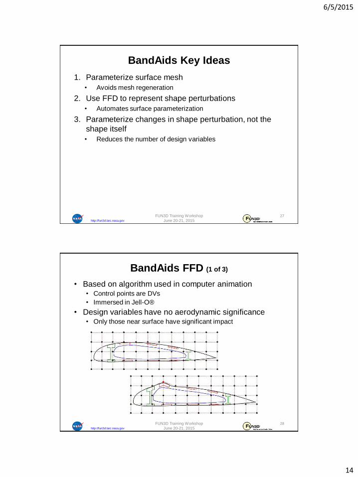
1. Parameterize surface mesh
• Avoids mesh regeneration
2. Use FFD to represent shape perturbations
• Automates surface parameterization
3. Parameterize changes in shape perturbation, not the
shape itself
• Reduces the number of design variables
BandAids Key Ideas
FUN3D Training Workshop
June 20-21, 2015
27
http://fun3d.larc.nasa.gov
• Based on algorithm used in computer animation• Control points are DVs
• Immersed in Jell-O®
• Design variables have no aerodynamic significance• Only those near surface have significant impact
BandAids FFD (1 of 3)
FUN3D Training Workshop
June 20-21, 2015
28
6/5/2015
15
http://fun3d.larc.nasa.gov
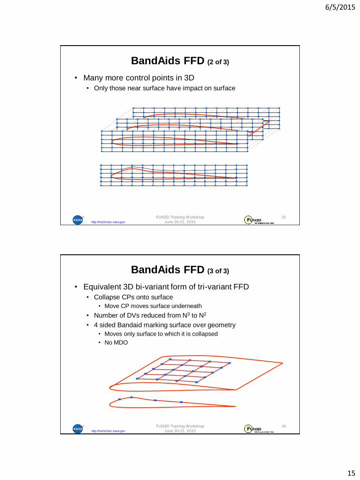
• Many more control points in 3D
• Only those near surface have impact on surface
BandAids FFD (2 of 3)
FUN3D Training Workshop
June 20-21, 2015
29
http://fun3d.larc.nasa.gov
• Equivalent 3D bi-variant form of tri-variant FFD
• Collapse CPs onto surface
• Move CP moves surface underneath
• Number of DVs reduced from N3 to N2
• 4 sided Bandaid marking surface over geometry
• Moves only surface to which it is collapsed
• No MDO
BandAids FFD (3 of 3)
FUN3D Training Workshop
June 20-21, 2015
30

6/5/2015
16
http://fun3d.larc.nasa.gov
• Shape changes are small
• Can be represented with fewer CPs than surface
• Maintains surface mesh character/quality
BandAids Parameterizes Changes
NURBS control points for
camber & thickness
Baseline
surface
mesh
Design
variable
vector
Surface
mesh point
Shape
changes
( ) ( )b
n n nr v r r v
FUN3D Training Workshop
June 20-21, 2015
31
http://fun3d.larc.nasa.gov
• Distributed as source code
• Single Makefile uses GNU C compiler (gcc)
• Any localization must be done manually
• Creates a single executable
• `bandAids` parameterization and deformation
BandAids Installation
FUN3D Training Workshop
June 20-21, 2015
32
6/5/2015
17
http://fun3d.larc.nasa.gov
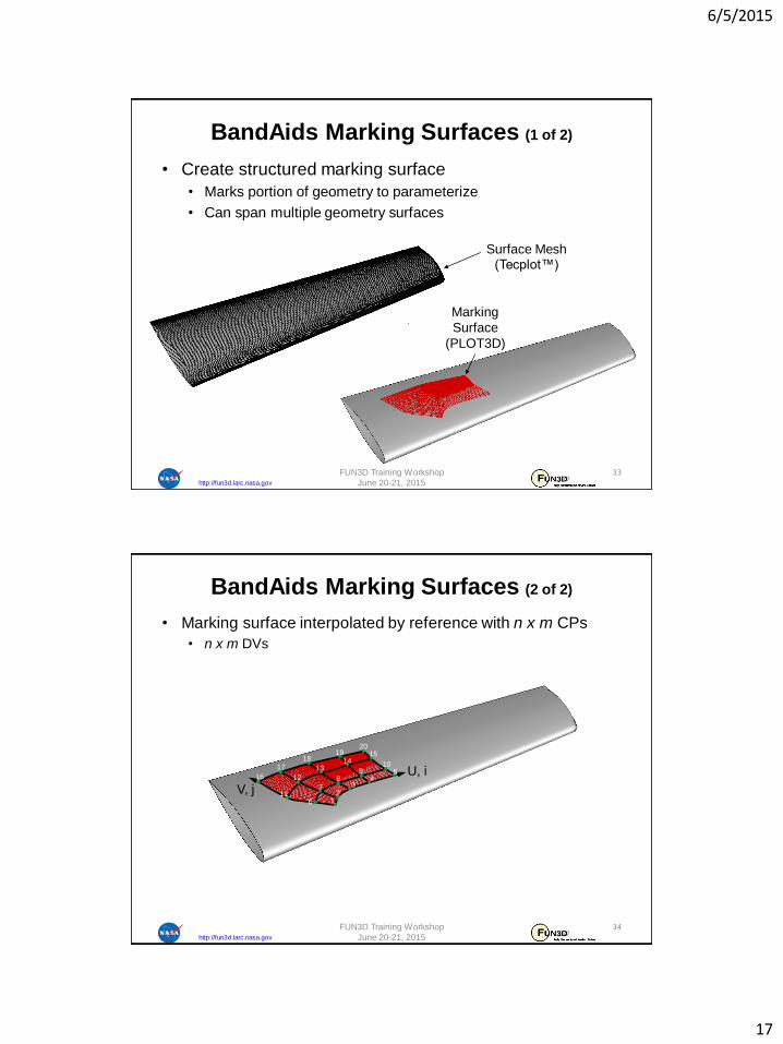
• Create structured marking surface
• Marks portion of geometry to parameterize
• Can span multiple geometry surfaces
BandAids Marking Surfaces (1 of 2)
Marking
Surface
(PLOT3D)
Surface Mesh (Tecplot™)
FUN3D Training Workshop
June 20-21, 2015
33
http://fun3d.larc.nasa.gov
• Marking surface interpolated by reference with n x m CPs
• n x m DVs
BandAids Marking Surfaces (2 of 2)
FUN3D Training Workshop
June 20-21, 2015
34
U, i
V, j1
23
45
6
78
910
11
12
1314
15
16
1718
1920
6/5/2015
18
http://fun3d.larc.nasa.gov
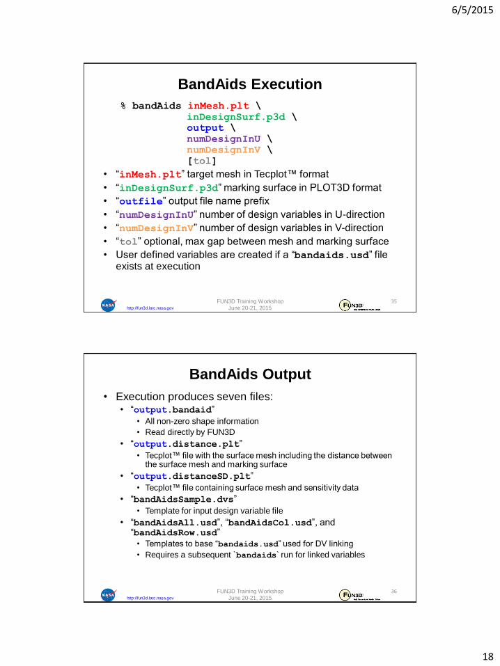
% bandAids inMesh.plt \
inDesignSurf.p3d \
output \
numDesignInU \
numDesignInV \
[tol]
• “inMesh.plt” target mesh in Tecplot™ format
• “inDesignSurf.p3d” marking surface in PLOT3D format
• “outfile” output file name prefix
• “numDesignInU” number of design variables in U-direction
• “numDesignInV” number of design variables in V-direction
• “tol” optional, max gap between mesh and marking surface
• User defined variables are created if a “bandaids.usd” file exists at execution
BandAids Execution
FUN3D Training Workshop
June 20-21, 2015
35
http://fun3d.larc.nasa.gov
• Execution produces seven files:• “output.bandaid”
• All non-zero shape information
• Read directly by FUN3D
• “output.distance.plt”
• Tecplot™ file with the surface mesh including the distance between the surface mesh and marking surface
• “output.distanceSD.plt”
• Tecplot™ file containing surface mesh and sensitivity data
• “bandAidsSample.dvs”
• Template for input design variable file
• “bandAidsAll.usd”, “bandAidsCol.usd”, and “bandAidsRow.usd”
• Templates to base “bandaids.usd” used for DV linking
• Requires a subsequent `bandaids` run for linked variables
BandAids Output
FUN3D Training Workshop
June 20-21, 2015
36
6/5/2015
19
http://fun3d.larc.nasa.gov
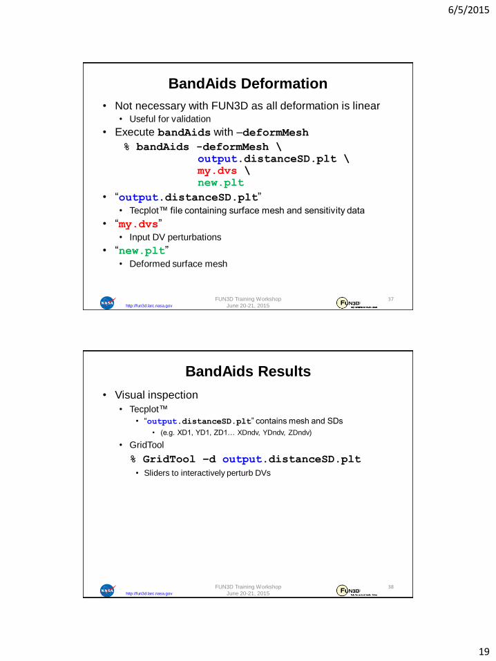
• Not necessary with FUN3D as all deformation is linear• Useful for validation
• Execute bandAids with –deformMesh
% bandAids -deformMesh \
output.distanceSD.plt \
my.dvs \
new.plt
• “output.distanceSD.plt”
• Tecplot™ file containing surface mesh and sensitivity data
• “my.dvs”
• Input DV perturbations
• “new.plt”
• Deformed surface mesh
BandAids Deformation
FUN3D Training Workshop
June 20-21, 2015
37
http://fun3d.larc.nasa.gov
• Visual inspection
• Tecplot™
• “output.distanceSD.plt” contains mesh and SDs
• (e.g. XD1, YD1, ZD1… XDndv, YDndv, ZDndv)
• GridTool
% GridTool –d output.distanceSD.plt
• Sliders to interactively perturb DVs
BandAids Results
FUN3D Training Workshop
June 20-21, 2015
38
6/5/2015
20
http://fun3d.larc.nasa.gov
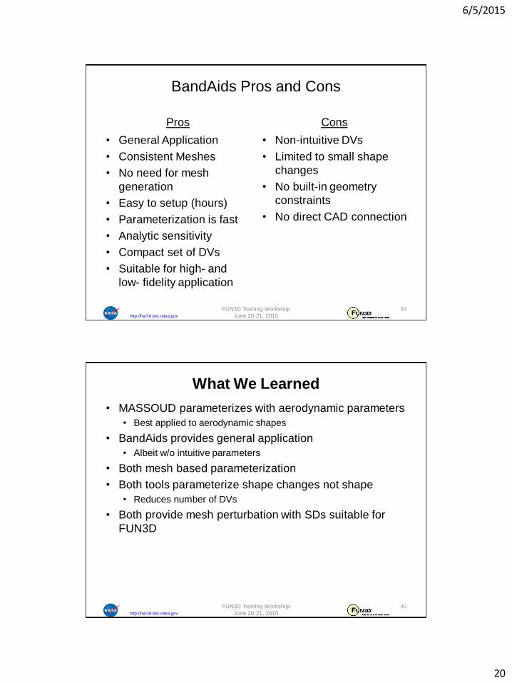
BandAids Pros and Cons
Pros
• General Application
• Consistent Meshes
• No need for mesh
generation
• Easy to setup (hours)
• Parameterization is fast
• Analytic sensitivity
• Compact set of DVs
• Suitable for high- and
low- fidelity application
Cons
• Non-intuitive DVs
• Limited to small shape
changes
• No built-in geometry
constraints
• No direct CAD connection
FUN3D Training Workshop
June 20-21, 2015
39
http://fun3d.larc.nasa.gov
• MASSOUD parameterizes with aerodynamic parameters
• Best applied to aerodynamic shapes
• BandAids provides general application
• Albeit w/o intuitive parameters
• Both mesh based parameterization
• Both tools parameterize shape changes not shape
• Reduces number of DVs
• Both provide mesh perturbation with SDs suitable for
FUN3D
What We Learned
FUN3D Training Workshop
June 20-21, 2015
40