Embed Size (px)
DESCRIPTION
sfsdfsdds sdf sfgsdfg sfgws gsdrfgws sdfgwd sdfg wdf
Citation preview
Nitrogen Generator using Pressure Swing Adsorption
Pressure swing adsorption (PSA) is a technology used to separate some gas species from a mixture of gases under pressure according to the species' molecular characteristics and affinity for an adsorbent material. Pressure swing adsorption processes rely on the fact that under high pressure, gases tend to be attracted to solid surfaces, or "adsorbed". The higher the pressure, the more gas is adsorbed; when the pressure is reduced, the gas is released, or desorbed. PSA processes can be used to separate nitrogen and oxygen gases in a mixture because different gases tend to be attracted to different solid surfaces more or less strongly. This leaves an enriched supply of nitrogen gas, making this an ideal processs for a nitrogen generator.
If a gas mixture such as air, for example, is passed under pressure through a vessel containing an adsorbent bed of zeolite that attracts nitrogen more strongly than it does oxygen, part or all of the nitrogen will stay in the bed, and the gas coming out of the vessel will be enriched in oxygen. When the bed reaches the end of its capacity to adsorb nitrogen, it can be regenerated by reducing the pressure, thereby releasing the adsorbed nitrogen. It is then ready for another cycle of producing oxygen enriched air.
Using two adsorbent vessels allows near-continuous production of the target gas. It also permits so-called pressure equalization, where the gas leaving the vessel being depressurised is used to partially pressurise the second vessel. This results in significant energy savings, and is common industrial practice.
This brief tutorial will show you how to build your own. It will first go over the theory and then the construction. This enables you to have an endless supply of pure N2. You can use it to fill your tires, power tools, or even cool it to make liquid nitrogen. All of the supplies are easy to obtain.
The PSA provides a pure nitrogen stream for my homebuilt liquid nitrogen generator. You can find the tutorial for producing liquid nitrogen in your garage here.
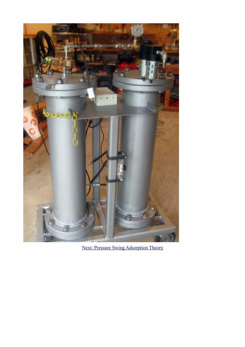
Below is a picture of my PSA on a movable plateform. Shown are two tower beds connected with 316 1/4" stainless pipe. The input goes through two filters. Two valves control flow into and out of each tower bed. A controller,shown in the center, directs the valves. At the bottom, one can see the high pressure tubing joining to the rotometer.
Object 1
Object 2
Object 3Object 4
Object 5
Object 6Object 7
Object 8
Object 9Object 10
Object 11
Object 12Object 13
Object 14
Object 15Object 16
Object 17
Object 18Object 19
Object 20
Object 21Object 22
Object 23
Object 24
Object 25Object 26
Object 27
CMS : Carbon Molecular Sieve
Nitrogen generation by the Pressure Swing Adsorption (PSA) process is a technology that separates N2 from a mixture of gases under pressure according to the special selective adsorption characteristics of the Carbon Molecular Sieves (CMS). Carbon molecular sieve is a non-polar adsorbent, derived from carbonaceous matter, that has different adsorptive rate for oxygen and nitrogen. CMS contains tiny pores of a precise and uniform size that is used as an adsorbent for gases. When the pressure is high enough, the oxygen molecules, which pass through the pores of CMS much faster than the nitrogen molecules, are adsorbed; nitrogen molecules remains free in the gas stream, leaving an enriched N2 gas phase. The CMS releases the oxygen when the system lowers the pressure. This regenerates the CMS so it is ready for another cycle of producing nitrogen enriched air.
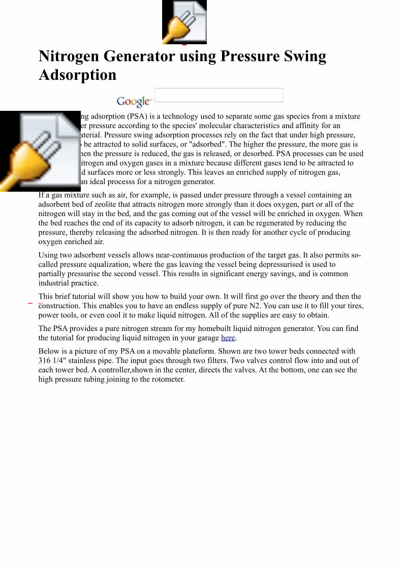
CMS looks like small, black grains 1.0x2.0 mm in size and a weight near 650 g/L. Saturation is usually reached near 60 seconds under a pressure of 0.8 Mpa (116 PSI). CMS comes in different grades, which tells you the purity of N2 gas you achieve under a certain pressure. My PSA has about 40kg of CMS-H, which gives me 98.5-99% N2 at a flow rate of 1.05 SCFM (about 30 L/min).
Above is some CMS with a bottle cap for size comparison.
Next: CMS structure and animations
CMS Structure
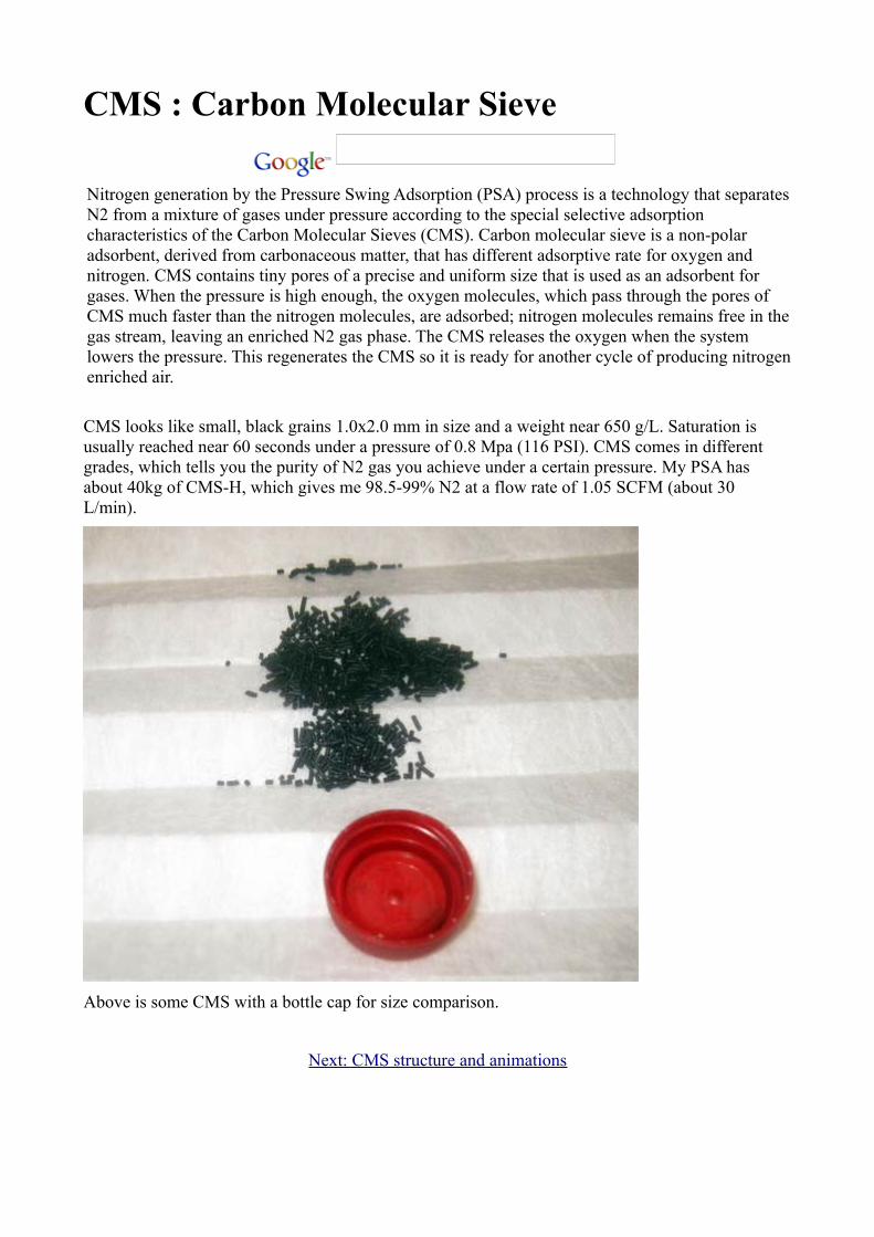
CMS Oxygen has a larger atomic number than nitrogen, so one would expect this to be the bigger molecule. However, due to various electrical forces acting on the electron shell, the effective size of the nitrogen molecule is bigger than oxygen molecule. Under pressure, O2 selectively enters the pores at a higher rate than the N2. O2 leaves the pores during depressurization.
One angstom = 0.1 x 10⁻⁶ millimeters or 0.0001 um
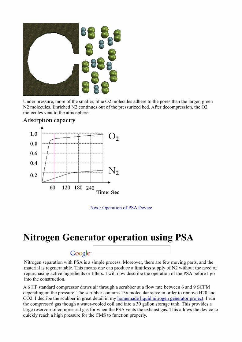
Under pressure, more of the smaller, blue O2 molecules adhere to the pores than the larger, green N2 molecules. Enriched N2 continues out of the pressurized bed. After decompression, the O2 molecules vent to the atmosphere.
Next: Operation of PSA Device
Nitrogen Generator operation using PSA
Nitrogen separation with PSA is a simple process. Moreover, there are few moving parts, and the material is regeneratable. This means one can produce a limitless supply of N2 without the need of repurchasing active ingredients or filters. I will now describe the operation of the PSA before I go into the construction.
A 6 HP standard compressor draws air through a scrubber at a flow rate between 6 and 9 SCFM depending on the pressure. The scrubber contains 13x molecular sieve in order to remove H20 and CO2. I decribe the scubber in great detail in my homemade liquid nitrogen generator project. I run the compressed gas though a water-cooled coil and into a 30 gallon storage tank. This provides a large reservoir of compressed gas for when the PSA vents the exhaust gas. This allows the device to quickly reach a high pressure for the CMS to function properly.
The compressed, water and CO2-free gas goes through two filters. The first removes remaining water vapor and large particles (1 um). The second is a 0.01 micron filter. This is necessary to protect the CMS material from getting clogged with micro-debri. A pressure gauge monitors the pressure entering the system and the compressor has a 150 psi pressure-release valve.
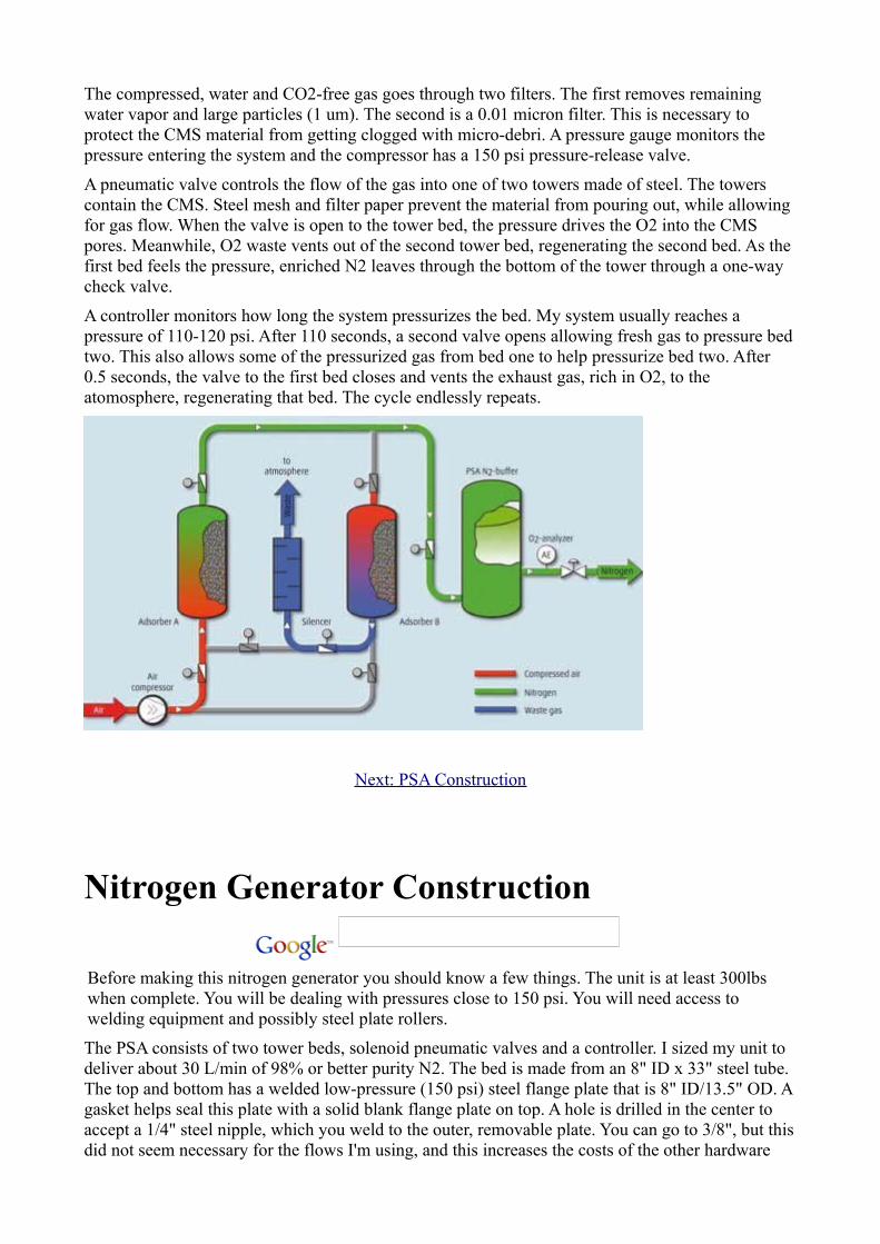
A pneumatic valve controls the flow of the gas into one of two towers made of steel. The towers contain the CMS. Steel mesh and filter paper prevent the material from pouring out, while allowing for gas flow. When the valve is open to the tower bed, the pressure drives the O2 into the CMS pores. Meanwhile, O2 waste vents out of the second tower bed, regenerating the second bed. As the first bed feels the pressure, enriched N2 leaves through the bottom of the tower through a one-way check valve.
A controller monitors how long the system pressurizes the bed. My system usually reaches a pressure of 110-120 psi. After 110 seconds, a second valve opens allowing fresh gas to pressure bed two. This also allows some of the pressurized gas from bed one to help pressurize bed two. After 0.5 seconds, the valve to the first bed closes and vents the exhaust gas, rich in O2, to the atomosphere, regenerating that bed. The cycle endlessly repeats.
Next: PSA Construction
Nitrogen Generator Construction
Before making this nitrogen generator you should know a few things. The unit is at least 300lbs when complete. You will be dealing with pressures close to 150 psi. You will need access to welding equipment and possibly steel plate rollers.
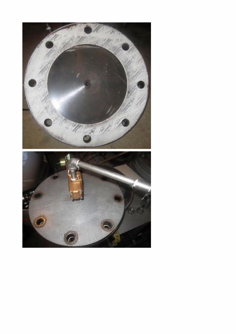
The PSA consists of two tower beds, solenoid pneumatic valves and a controller. I sized my unit to deliver about 30 L/min of 98% or better purity N2. The bed is made from an 8" ID x 33" steel tube. The top and bottom has a welded low-pressure (150 psi) steel flange plate that is 8" ID/13.5" OD. A gasket helps seal this plate with a solid blank flange plate on top. A hole is drilled in the center to accept a 1/4" steel nipple, which you weld to the outer, removable plate. You can go to 3/8", but this did not seem necessary for the flows I'm using, and this increases the costs of the other hardware
and pipes.
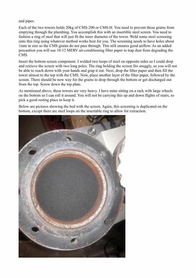
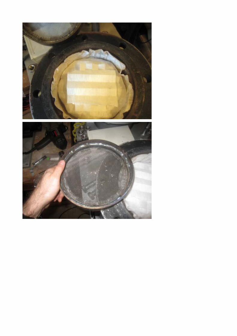
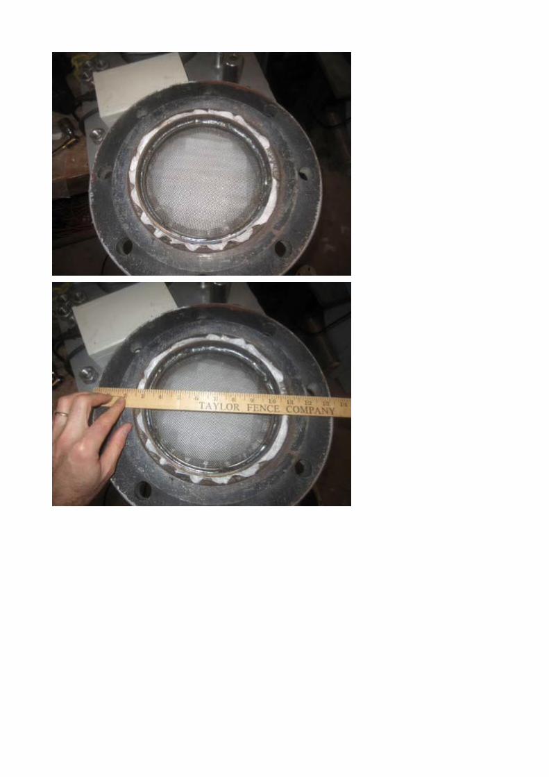
Each of the two towers holds 20kg of CMS-200 or CMS-H. You need to prevent these grains from emptying through the plumbing. You accomplish this with an insertible steel screen. You need to fashion a ring of steel that will just fit the inner diameter of the tower. Weld some steel screening onto this ring using whatever method works best for you. The screening needs to have holes about 1mm in size so the CMS grains do not pass through. This still ensures good airflow. As an added precaution you will use 10-12 MERV air-conditioning filter paper to trap dust from degrading the CMS.
Insert the bottom screen component. I welded two loops of steel on opposite sides so I could drop and retrieve the screen with two long poles. The ring holding the screen fits snuggly, so you will not be able to reach down with your hands and grap it out. Next, drop the filter paper and then fill the tower almost to the top with the CMS. Now, place another layer of the filter paper, followed by the screen. There should be now way for the grains to drop through the bottom or get discharged out from the top. Screw down the top plate.
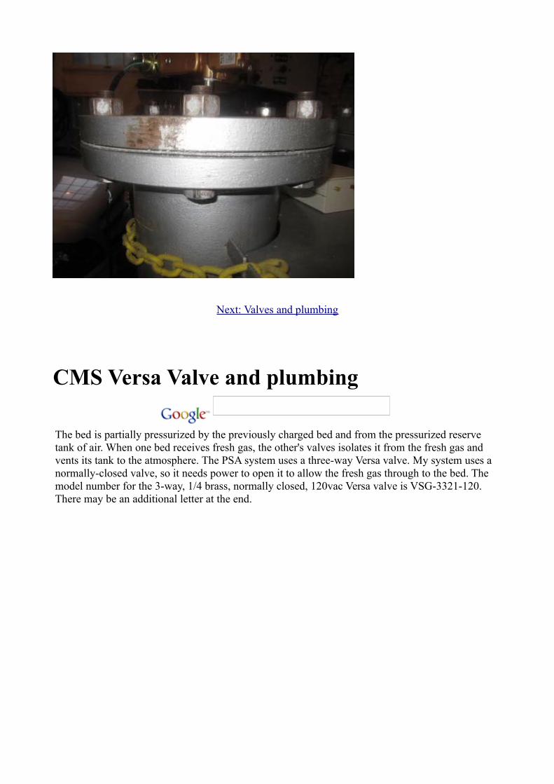
As mentioned above, these towers are very heavy. I have mine sitting on a rack with large wheels on the bottom so I can roll it around. You will not be carrying this up and down flights of stairs, so pick a good resting place to keep it.
Below are pictures showing the bed with the screen. Again, this screening is duplicated on the bottom, except there are steel loops on the insertable ring to allow for extraction.
Next: Valves and plumbing
CMS Versa Valve and plumbing
The bed is partially pressurized by the previously charged bed and from the pressurized reserve tank of air. When one bed receives fresh gas, the other's valves isolates it from the fresh gas and vents its tank to the atmosphere. The PSA system uses a three-way Versa valve. My system uses a normally-closed valve, so it needs power to open it to allow the fresh gas through to the bed. The model number for the 3-way, 1/4 brass, normally closed, 120vac Versa valve is VSG-3321-120. There may be an additional letter at the end.
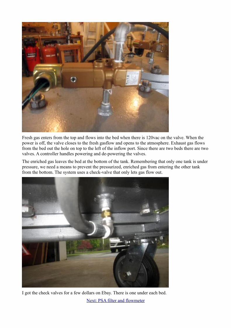
Fresh gas enters from the top and flows into the bed when there is 120vac on the valve. When the power is off, the valve closes to the fresh gasflow and opens to the atmosphere. Exhaust gas flows from the bed out the hole on top to the left of the inflow port. Since there are two beds there are two valves. A controller handles powering and de-powering the valves.
The enriched gas leaves the bed at the bottom of the tank. Remembering that only one tank is under pressure, we need a means to prevent the pressurized, enriched gas from entering the other tank from the bottom. The system uses a check-valve that only lets gas flow out.
I got the check valves for a few dollars on Ebay. There is one under each bed.
Next: PSA filter and flowmeter
CMS filter and flowmeter
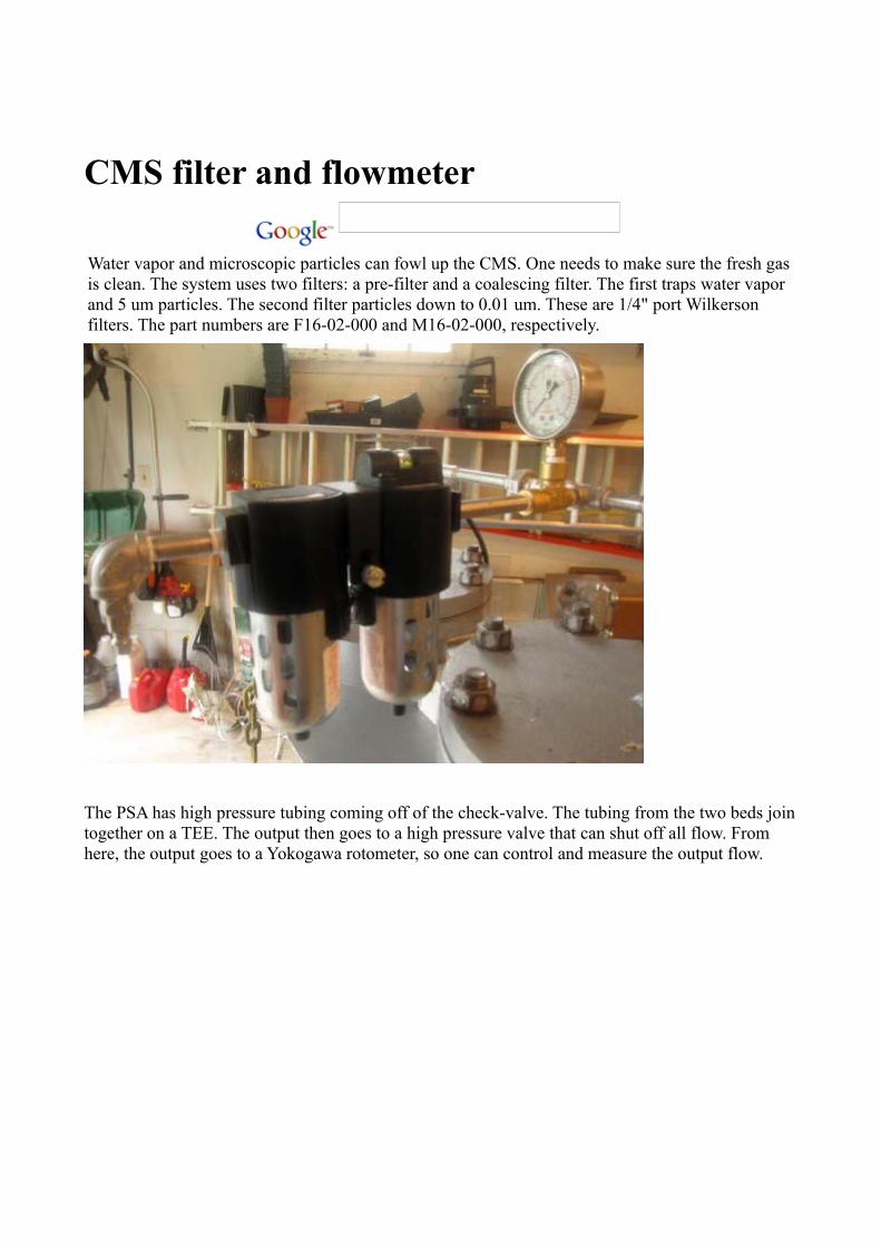
Water vapor and microscopic particles can fowl up the CMS. One needs to make sure the fresh gas is clean. The system uses two filters: a pre-filter and a coalescing filter. The first traps water vapor and 5 um particles. The second filter particles down to 0.01 um. These are 1/4" port Wilkerson filters. The part numbers are F16-02-000 and M16-02-000, respectively.
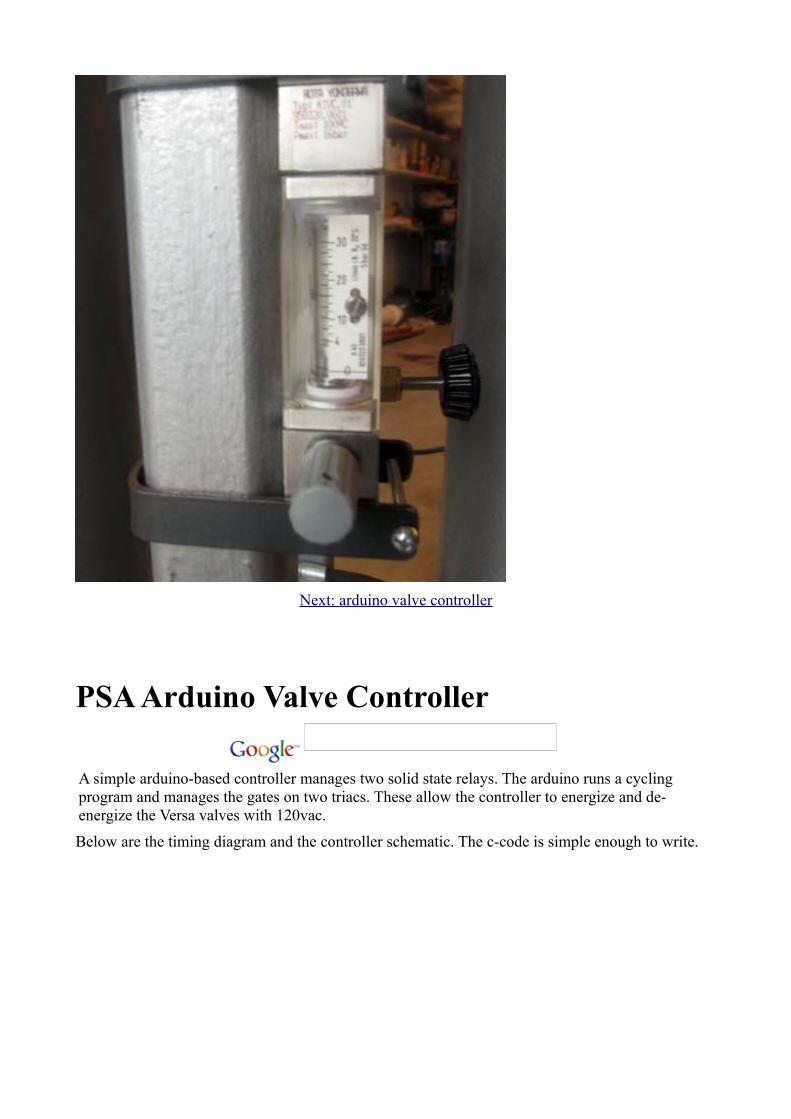
The PSA has high pressure tubing coming off of the check-valve. The tubing from the two beds join together on a TEE. The output then goes to a high pressure valve that can shut off all flow. From here, the output goes to a Yokogawa rotometer, so one can control and measure the output flow.
Next: arduino valve controller
PSA Arduino Valve Controller
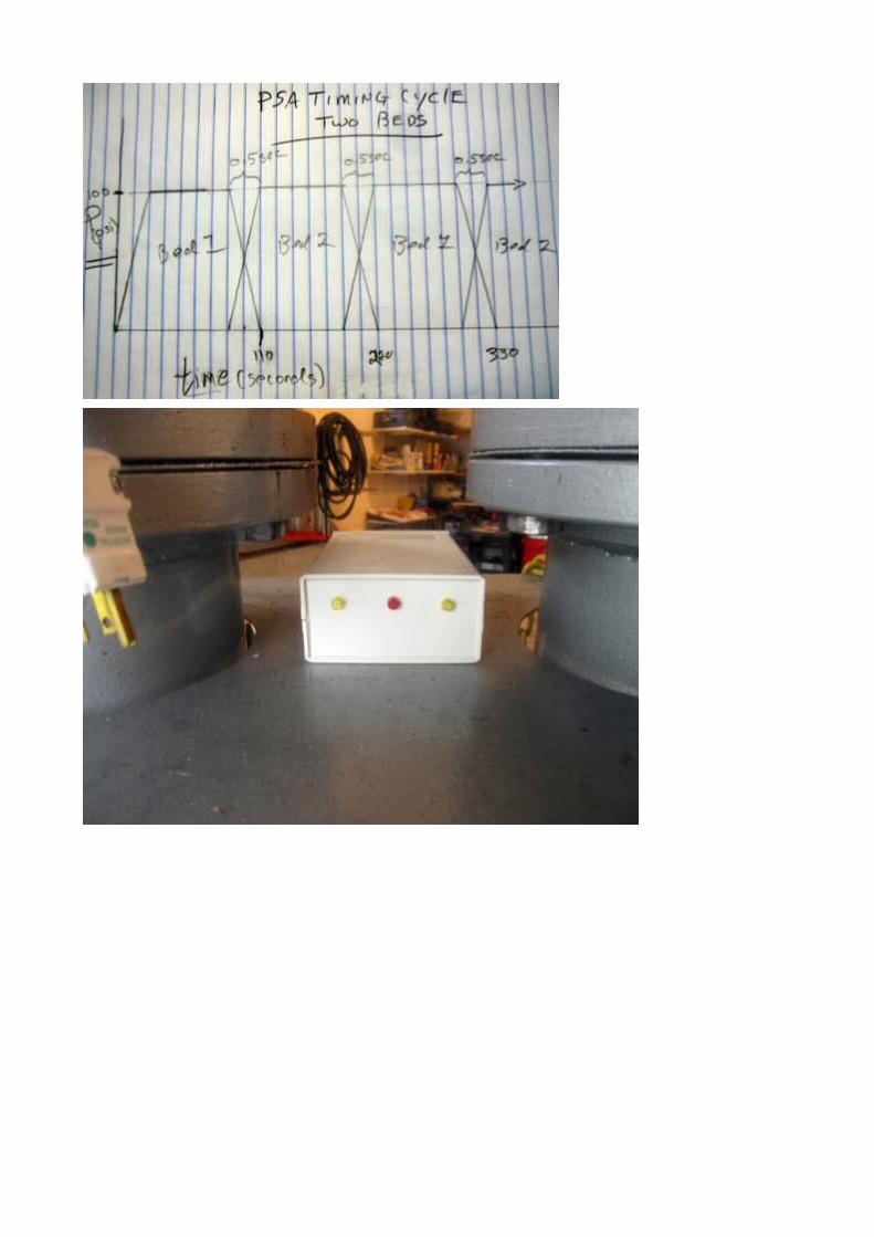
A simple arduino-based controller manages two solid state relays. The arduino runs a cycling program and manages the gates on two triacs. These allow the controller to energize and de-energize the Versa valves with 120vac.
Below are the timing diagram and the controller schematic. The c-code is simple enough to write.
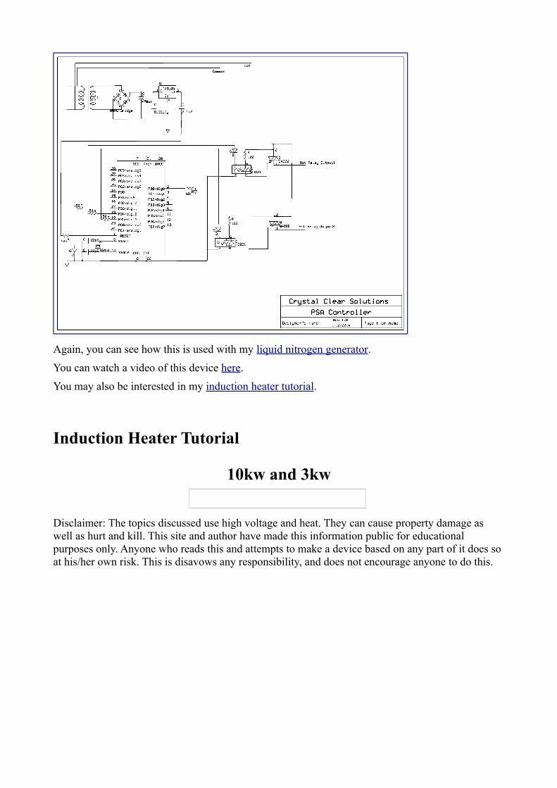
Again, you can see how this is used with my liquid nitrogen generator.
You can watch a video of this device here.
You may also be interested in my induction heater tutorial.
Induction Heater Tutorial
10kw and 3kw
Disclaimer: The topics discussed use high voltage and heat. They can cause property damage as well as hurt and kill. This site and author have made this information public for educational purposes only. Anyone who reads this and attempts to make a device based on any part of it does so at his/her own risk. This is disavows any responsibility, and does not encourage anyone to do this.
An induction heater is an interesting device, allowing one to rapidly heat a metal object. With enough power, one can even melt metal. The induction heater works without the need for fossil fuels, and can anneal and heat objects of various shapes. I set out to make an induction heater that could melt steel and aluminum. So far I have been able to feed an input power of over 3 kilowatts! Now that I have done this I would like to share how it works, and how you can build one. At the end of the tutorial I will discuss and show you how to build a levitation coil that will allow you to boil metals while suspended in mid air!
The first part of this tutorial will go through my development of a 3kw inverter. My initial goal was to rapidly heat metals. My next goal was to levitate metals. I succeeded, but realized that I could not levitate solid copper and steel. Their density was too great for the magnetic field. This was my final goal: to levitate and suspend molten copper and steel. At the end of this tutorial I will go into the development of a 10kw unit that realized this goal. I will also elaborate on the problems that had to be overcome in order to achieve this.
Let's start.
My induction heater is an inverter. An inverter takes a DC power source and converts it into AC power. The AC power drives a transformer which is coupled to a series LC tank. The inverter frequency is set to the tank's resonant frequency, allowing the generation of very high currents within the tank's coil. The coil is coupled to the workpiece and sets up eddy currents. These currents, traveling through a conductive, but slightly resistive workpiece, heat the piece. Remember, Power = Heat = R*I^2. The workpiece is like a one-turn coil; the work coils has several turns. Thus, we have a step-down transformer, so even higher currents are generated in the workpiece.
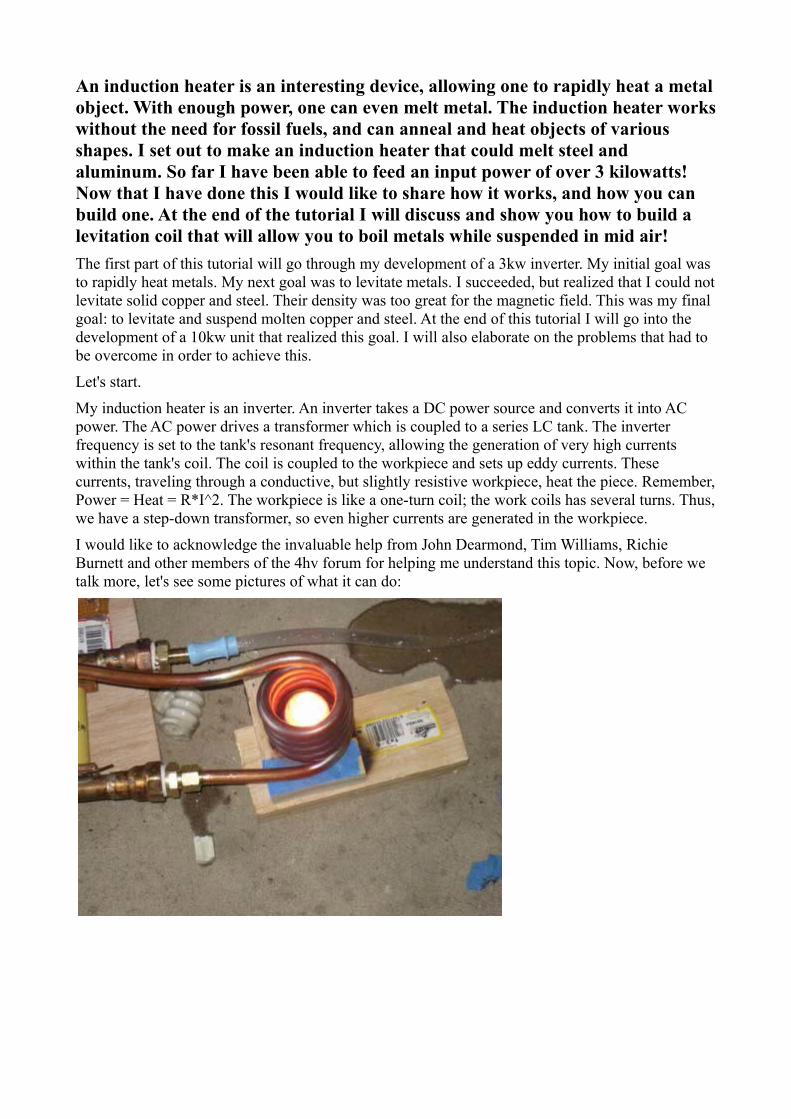
I would like to acknowledge the invaluable help from John Dearmond, Tim Williams, Richie Burnett and other members of the 4hv forum for helping me understand this topic. Now, before we talk more, let's see some pictures of what it can do:
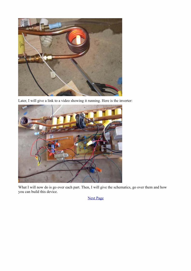
Later, I will give a link to a video showing it running. Here is the inverter:
What I will now do is go over each part. Then, I will give the schematics, go over them and how you can build this device.
Next Page