Embed Size (px)
Citation preview
Gesture-Controlled LED Orb Final Project Report December 5, 2017
E155
Christopher Kotcherha and Nicholas Sakowski
Abstract
There are endless possibilities of the complex systems we can make with readily existing gadgets such as
LED strips, accelerometers, and EKG sensors. We live in an opportune time where we possess a bounty
of such easy-to-use digital technology alongside a lack of fun, inventive devices compared to all those that
could be. This project attempts to strike a new vein in that underexploited world of fun devices and
presents users the opportunity to play with light and color in new, creative ways. The “Magic Orb”
prototypes an LED globe controlled by a wrist-worn device with the assistance of a microcontroller and
FPGA. Motion data captured by the wristband, such as acceleration, rotation, and hand gestures, are
interpreted by the microcontroller and sent off to the FPGA. This device uses a hardware-generated
PWM signal to control the color of each LED in the globe, resulting in a real-time user experience
consisting of multiple pre-programed animations and games.
Introduction
Our final project is an LED orb (322 individually RGB programmable LEDs) which displays motion-controlled animations based on IMU data. The user experience consists of wearing a Myo™ armband and signaling new animation states on the orb via specific hand gestures, recognizable by the Myo’s 8 EKG sensors. At a high level, the user experience with the orb was organized into a top menu, navigable via gestures, and selectable mini-games, which are controllable via user motions.
The top menu functioned by having the orb emit a single color to indicate the currently selected mini-game. The user can ‘swipe’ through the list of games by making a ‘wave-out’ gesture with the hand equipped with a Myo. When the user decides on a game choice (unique by color), they can make a ‘fist’ gesture to begin the mini-game. However, at any time during the games, the user can make a ‘wave-in’ gesture to exit the game back to the original menu.
For this project, the user experience consisted of two playable mini-games. The color ‘indigo’ indicated the ‘color spectrum’ game. Once entered, the orb will display a single color at any given time, but with its various colors mapped to correspond to the user’s arm orientation (pitch). Through this experience, the user can smoothly and quickly transition between the colors of our spectrum by motioning their arm up and down.
The second available game, indicated by the menu color of ‘green’, is the ‘ring-game.’ Once this game is begun, the orb would only display colors on a single axis, effectively displaying a series of concentric rings. However, each of the red rings would have a subset of 4 green LEDs indicating a subsection of the ring. These subsections would be scattered about, with the goal of this game to align the subsections together at the top of the orb. The currently ‘selected’ ring would display blue and green (subsection) instead of red and green. The user can change their selected ring by jerking their arm forward (shift up) or backward (shift down). They must shift the orientation of the subsection along its host ring by rolling their arm counterclockwise (left shift) or clockwise (right shift). Once the rings are all aligned, a victory animation plays and the user is returned to the menu.
New Hardware
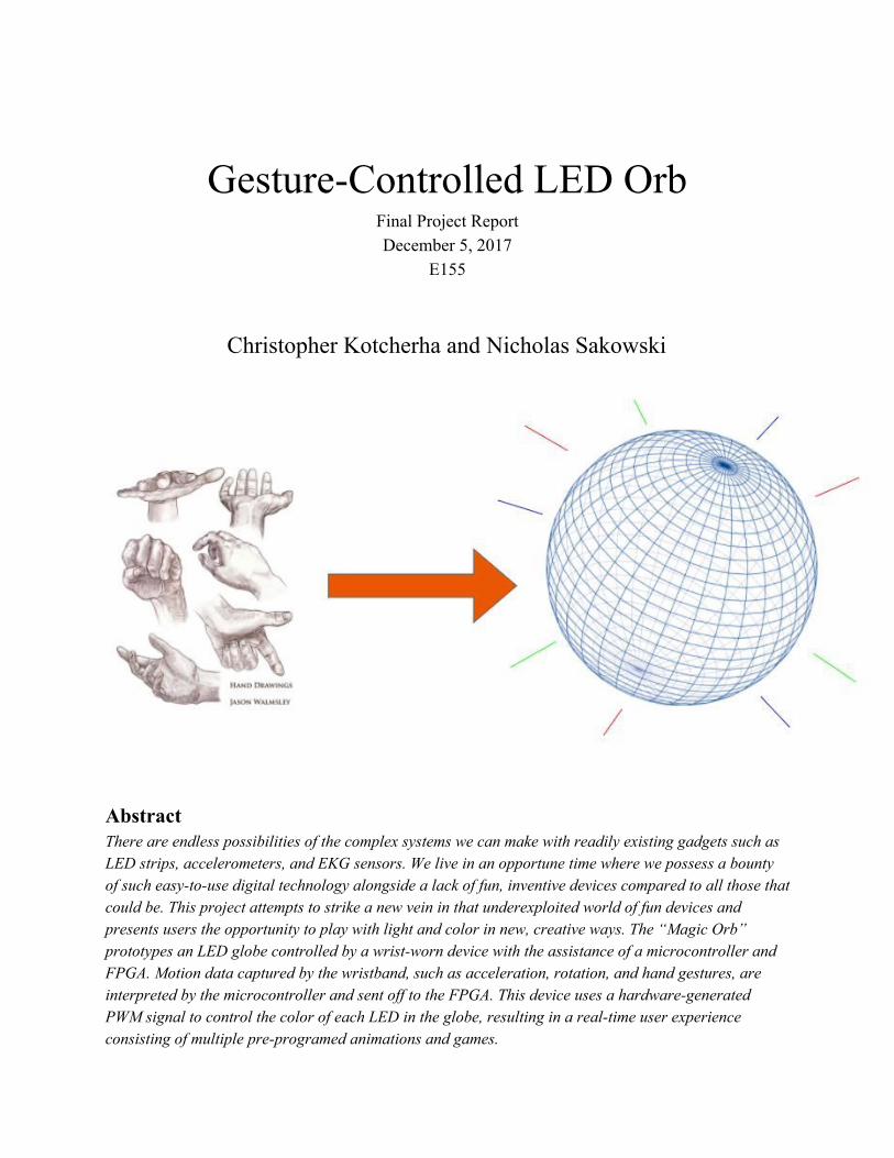
The LED orb was constructed from a WS2812b strip arranged into 14 rings (two orthogonal groups/axis of seven arranged concentrically) inside a translucent, white acrylic lighting fixture. These LEDs were chosen as they are capable of producing a large range of colors and, despite being so popular, few people have managed to control them with FPGAs. A range of colors (red, orange, yellow, green, blue, teal, violet, magenta) can be displayed and individual LEDs can be controlled via C scripts on the Raspberry Pi (which send data to the FPGA via SPI). Any combination or pattern of these colors is possible, since each LED is individually programmable. Also various custom animations (multiple display frames in sequence) are implemented, but any scripted sequence of patterns is possible with this architecture.
Figure 1: LED orb - 2 axis structure
The most important concern during design and development is the timing specifications
presented by the LEDs. According to their datasheet, they operate as a serial register with PWM logic. The specifics of these specifications can be seen below as well as a graphic that demonstrates the three possible signals.
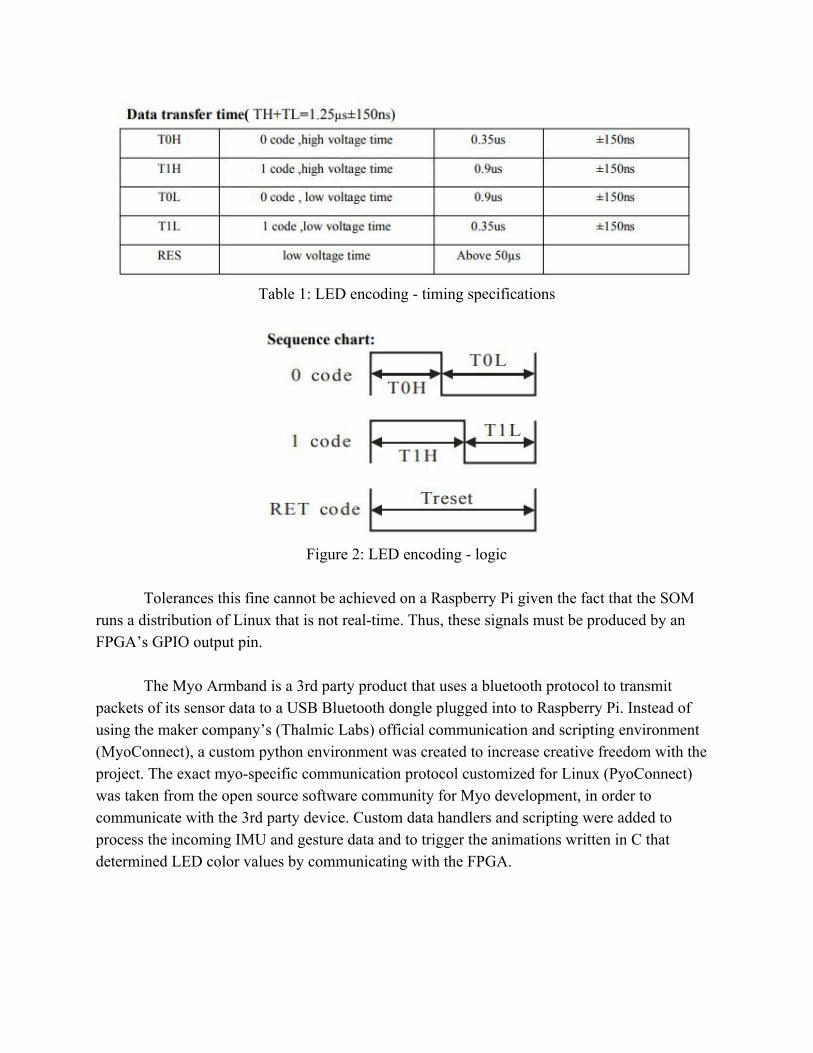
Table 1: LED encoding - timing specifications
Figure 2: LED encoding - logic
Tolerances this fine cannot be achieved on a Raspberry Pi given the fact that the SOM runs a distribution of Linux that is not real-time. Thus, these signals must be produced by an FPGA’s GPIO output pin.
The Myo Armband is a 3rd party product that uses a bluetooth protocol to transmit packets of its sensor data to a USB Bluetooth dongle plugged into to Raspberry Pi. Instead of using the maker company’s (Thalmic Labs) official communication and scripting environment (MyoConnect), a custom python environment was created to increase creative freedom with the project. The exact myo-specific communication protocol customized for Linux (PyoConnect) was taken from the open source software community for Myo development, in order to communicate with the 3rd party device. Custom data handlers and scripting were added to process the incoming IMU and gesture data and to trigger the animations written in C that determined LED color values by communicating with the FPGA.
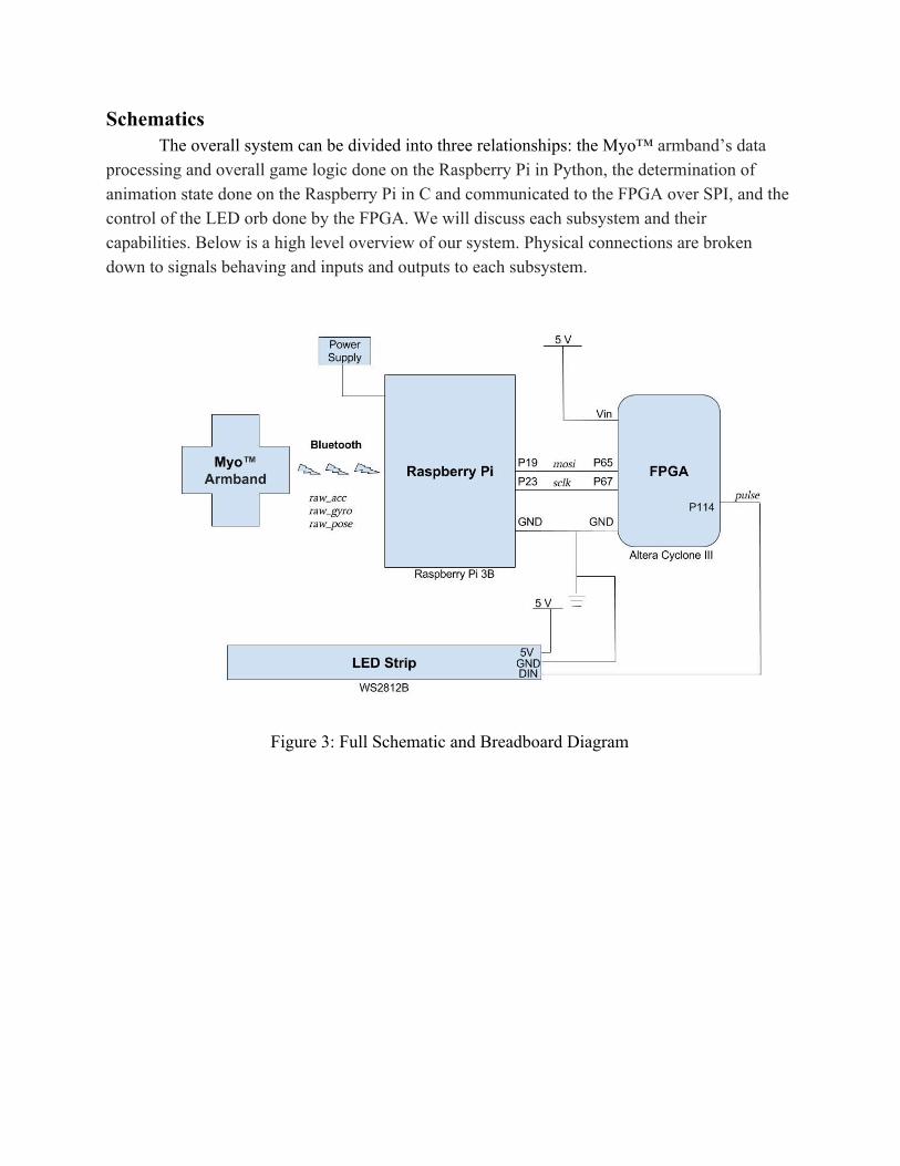
Schematics The overall system can be divided into three relationships: the Myo™ armband’s data
processing and overall game logic done on the Raspberry Pi in Python, the determination of animation state done on the Raspberry Pi in C and communicated to the FPGA over SPI, and the control of the LED orb done by the FPGA. We will discuss each subsystem and their capabilities. Below is a high level overview of our system. Physical connections are broken down to signals behaving and inputs and outputs to each subsystem.
Figure 3: Full Schematic and Breadboard Diagram
Software Design The python scripting environment on the Pi included 3 major components. The first of
which is the Myo-specific bluetooth protocol. As mentioned previously, this protocol was documented in the open source development community for the Myo-armband, and was implemented in python exactly as documented. Other than these existing files, there is no official datasheet or documentation by which the bluetooth communication and package parsing can be inferred.
The second part of the python environment involves a data handler for the incoming stream of gesture-recognition data. This gesture handler takes in the already-recognized gestures, since the Myo’s firmware has built in data interpretation for the EKG sensors specifically. The data comes in as strings such as ‘WAVEIN’, ‘WAVEOUT’, ‘FIST’, and other presets, but only when a gesture is recognized, otherwise no data enters the handler. This handler is specialized to manipulate the main menu and the current ‘highlighted mode’. ‘WAVEOUT’ swipes through the menu options (sets the highlighted mode), and calls a C executable that corresponds to the desired highlighted mode color. ‘FIST’ launches the currently selected game option (indigo = color spectrum, green = ring-game) by setting the global ‘mode’ variable to that game’s value (menu is default mode 0). ‘WAVEIN’ exits any game back to the main menu by setting the mode back to 0.
The third aspect of the python code is the IMU data handler. It streams in all the gyroscope and accelerometer data at 50Hz. This incoming motion data is then processed and interpreted by the mini-game scripts within the handler. Each game has an associated ‘mode’ so that only one game is running at any time. This variable is set by the menu interaction, as mentioned before. Once in one of the two game modes (mode 1 = color spectrum, mode 2 = ring game), the motion data is used to trigger certain events, and these events correspond to calling a C executable associated with an LED color or animation. For example, a roll-rate threshold (followed by a temporary halt on data processing to prevent multiple triggers in quick succession) causes the ring orientation in the ring-game to shift by updating a single argument in the ring_game executable call.
The link between the Raspberry Pi and the FPGA are a set of C executables which transmit the appropriate, encoded RGB data to be interpreted (the handling of this data will be discussed further in the ‘FPGA’ section). These files correspond to different LED animations and take in different arguments from a Python script depending on user motion data. The function of currently implemented executables include setting the orb one of eight solid colors and the 'ring game' mentioned in the Introduction. Motion data captured using the Python script is handled and a system call is made to the C file with data encoding the currently selected ring, the position of all 7 rings, and the win condition. These applications can be accessed from the orb’s 'main menu', a state in which the user swipes through solid colors on the orb which correspond to different games.

Each executable file sends an array of 162 chars (322 nibbles + 1 byte) to the FPGA over SPI. To save registers on the FPGA, this array is encoded such that each nibble corresponds to the color of one LED in the strip, with the last byte acting as a ‘stop-byte’ signal ('~'). The encoding is as follows:
0x0010 Red 0x0011 Orange 0x0100 Yellow 0x0101 Green 0x0110 Blue 0x1000 Teal 0x1001 Violet 0x1010 Magenta 0x0111_1110 Stop
Note that it is impossible to send a combination of encoded colors that could be confused
for the stop bit. The encodings shown were chosen as such for exactly that reason.
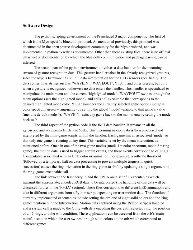
FPGA Design The LED strip used in this system (WS2812b) operates in series via PWM logic and has
very strict timing constraints discussed previously. To properly control the LED strip, we require the use of a real-time system such as an FPGA. With a 40 MHz clock and the ability to run complex operations in hardware, the Altera Cyclone IV is fully capable of creating pulse width modulated signals within the given 150 ns tolerances.
The purpose of the FPGA in this system is to interpret 161 bytes of encoded RGB data via SPI from the Raspberry Pi, decode said bytes to 322 24-bit RGB codes, and send those codes in sequence to the LED strip using PWM logic. We will now discuss the logic behind this operation in detail.
The hardware description can be divided into two major components: the SPI data handling, and the LED controller. Beginning with the SPI handler, we have two modules that work together to interpret 161 +1 bytes from the Raspberry Pi. The first, spi_slave_receive_only , contains a 1296 bit buffer that holds the last 162 bytes sent from the Pi. This module works on the Pi’s serial clock, sck. Another faster module, spi_data_grab, running on the FPGA clock checks to see if the 8 least significant bits of the first module’s buffer are equal to the ‘stop-byte’ ('~'). When this byte is encountered, the first 161 bytes are shifted to a signal named pi_data and the led controller is given a signal indicating that the data is ready to interpret.
A 161-byte bus was chosen over storing this data in RAM for convenience. At the time of design, this implementation made sense and made the datapath easier to visualize. This would become a hindrance, however, if data sent from the Pi was in the form of 1 byte per LED, as it would require more registers than the FPGA contains. It would be a great advantage in the future if the design was modified such that data from the Pi was stored into RAM sequentially and read out sequentially in the LED controller modules. This would allow the Pi to send more detailed information to the FPGA and could make writing the Pi-end software more easy for developers. This would not cost any additional lag to the design, but would make the SPI process twice as long (which would be a negligible difference to the user).
The second major component, the LED controller, does not operate until it sees the dat_ready signal go high. Comprised of two modules, stripcontrol and pwm , this major component translates each 4-bit ‘nibble’ from pi_data to a 24-bit RGB value by shifting the signal through a decoder. For each 3-byte ‘chunk’, stripcontrol indicates to pwm whether to send a 0 or a 1, starting with the most significant bit. The pwm module is the last step in the chain and acts as an FSM which alternates between sending long high signals with short low signals, and short high signals with low long signals. When a bit is sent via PWM, the pwm module sends a done signal to stripcontrol, and the process is repeated until 322*24 = 7728 bits have been processed over PWM. When all 322 nibbles have been processed, the pwm module is forced to wait for 50 μs, which indicates a ‘latch’ signal to the LED strip.The length of this part of the process takes 9.71 ms and is perceived as instantaneous by the user. A block diagram of the logic described is shown below.
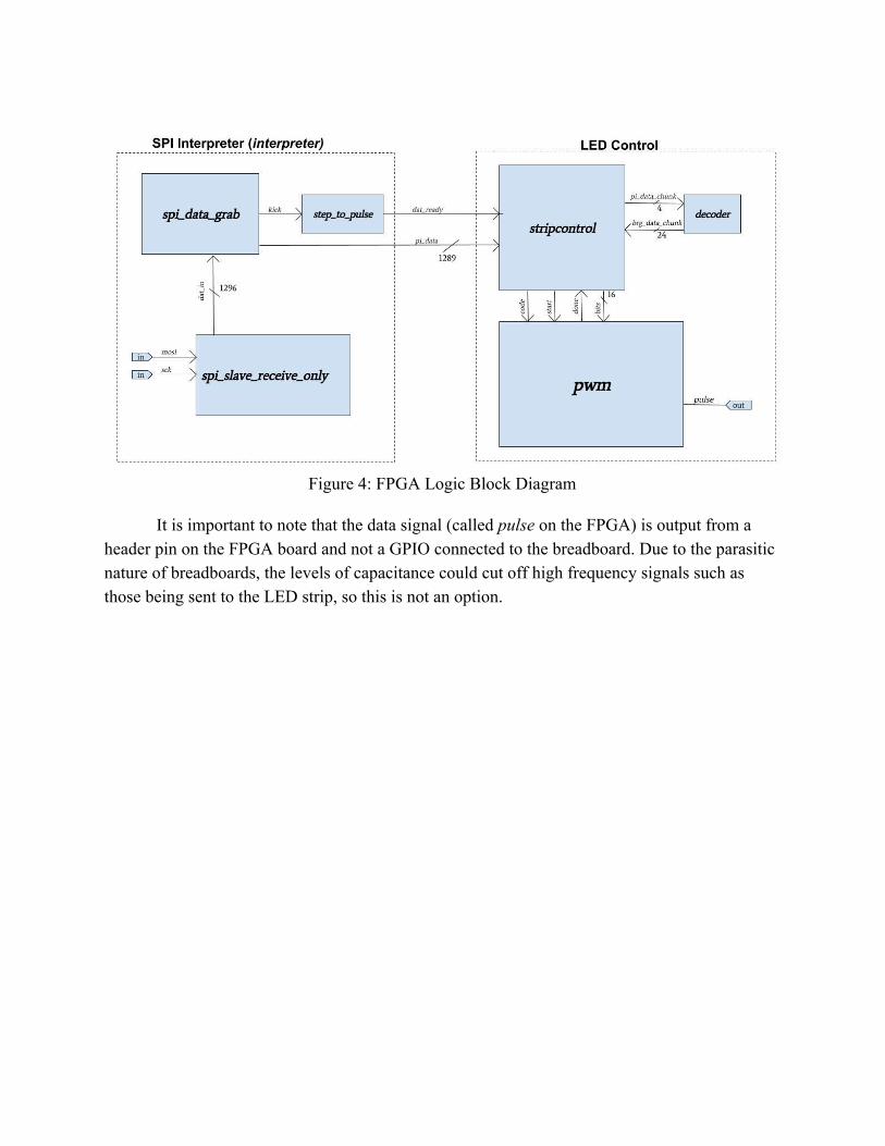
Figure 4: FPGA Logic Block Diagram
It is important to note that the data signal (called pulse on the FPGA) is output from a header pin on the FPGA board and not a GPIO connected to the breadboard. Due to the parasitic nature of breadboards, the levels of capacitance could cut off high frequency signals such as those being sent to the LED strip, so this is not an option.
Results
The performance of our final system is very close to the intended goals. Myo communication with the Raspberry Pi was flawless and low-latency. The python scripting executed exactly as designed, interfacing well with both incoming data and C executables. The C executables also executed flawlessly with SPI communication to the FPGA. The PWM from the FPGA is also highly reliable. Constructed hardware, including the LED display and orb also performed well with no maintenance required.
The only difference between the proposed design and the final product is the “focal point” game. This game would have allowed the user to control the position of a point of light on the orb with pitch and yaw hand motions. This design would have required the ability to easily map and translate arbitrary designs to the orb, which no previous animations had utilized. This was very close to becoming a reality with a vectorial approach on the Pi, but was not completely realized due to the lack of spatial resolution imposed by having to send 2 LEDs worth of information at a time over SPI. It was at this point that the consequences of not storing LED data in RAM on the FPGA came to fruition.
This method precalculates 322, 3-coordinate representations of vectors that point to each of the orb’s LEDs. To create designs, a ‘master vector’ is chosen and the dot product of the master and each of the other 322 vectors is taken. The value of this dot product is then sigmoid-ed to a scale of 1-7 and rounded to the nearest integer. This value then corresponds to a color in a specified color spectrum, leading to a rainbow gradient design growing in the direction of the master vector, or a single point/group of points that only exist at the tip of the master vector. This method, as mentioned previously, is only held back by the fact that 2 LEDs worth of information must be sent to the FPGA at a time, making the final resolution of the orb’s designs choppy and not pleasing to look at.

Parts List
Part Name Purpose Qty Unit Cost Cost
Raspberry Pi 3B Master/Wifi/Motion Estimator 1 - -
MicroMudd FPGA board
Slave/LED Driver 1 - -
12” Acrylic Globe Outside Cover 1 $16.97 $16.97
16.4’ RGB LED strip
LEDs 2 $19.69 $39.38
Power Wall Adapter (9 V)
Main Power 1 $11.99 $11.99
MYO wristband Gesture/Position Tracking 2 - -
Purchasing Out of Pocket ……………... $28.96 To be reimbursed …………. $51.36 Total: ……………………... $80.32
Appendix
// Nicho las Sakowski and Chris Kotcherha// Microprocessors Fina l Pro jec t
// This f i l e d e s c r i b e s the l o g i c requ i r ed to// manipulate WS2812B LED s t r i p , 322 e lements// long .
module f i n a l n s c k ( input l o g i c c lk ,input l o g i c r e s e t ,input l o g i c sck ,input l o g i c mosi ,output l o g i c pu l s e ) ; // Output to LED s t r i p
l o g i c dat ready ; // Data i s ready to be sent to LED s t r i pl o g i c [ 1 2 8 7 : 0 ] p i da ta ; // Last 322 n i b b l e s + 1 by te from pi
// Hanldes data from Pii n t e r p r e t e r i n t1 ( c lk , sck , mosi , p i data , dat ready ) ;
// In t e r p r e t s data and con t r o l s LED s t r i pl e d s l ed1 ( c lk , r e s e t , dat ready , p i data , pu l s e ) ;
endmodule
// SPI i n t e r p r e t a t i o n modulesmodule i n t e r p r e t e r ( input l o g i c c lk ,
input l o g i c sck ,input l o g i c mosi ,output l o g i c [ 1 2 8 7 : 0 ] p i data ,output l o g i c dat ready ) ;
l o g i c k i ck ; // Triggers l e d c o n t r o l l e rl o g i c [ 1 2 9 5 : 0 ] da t i n ; // A l l data from pi
// Handle SPI datas p i s l a v e r e c e i v e o n l y sp i ( sck , mosi , da t i n ) ;
// Te l l us when we ’ re good to read SPI data and pass i t onsp i da t a g r ab sdg ( c lk , dat in , p i data , k i ck ) ;
// Te l l LED con t r o l l e r when to s t a r tpu l s e r p( c lk , kick , dat ready ) ;
endmodule
// LED con t ro l modulesmodule l e d s ( input l o g i c c lk ,
input l o g i c r e s e t ,input l o g i c dat ready ,input l o g i c [ 1 2 8 7 : 0 ] p i data ,output l o g i c pu l s e ) ;
l o g i c s ta r t , code , done ;l o g i c [ 1 1 : 0 ] b i t s ;
// Trans la te SPI data to 24 b i t BRG datas t r i p c o n t r o l s t r i p 1 ( c lk , r e s e t , dat ready , p i data , done , code , s t a r t , b i t s ) ;
// LED s t r i p d r i v e rpwm pwm1( clk , r e s e t , code , b i t s , s t a r t , done , pu l s e ) ;
endmodule
1
// SPI s l a v e module to r e c e i v e data from Pi// Keeps t rack o f l a s t 1296 b i t s 322 n i b b l e s + 1 by temodule s p i s l a v e r e c e i v e o n l y ( input l o g i c sck , //From master
input l o g i c mosi ,output l o g i c [ 1 2 9 5 : 0 ] da t i n ) ;
a lway s f f @(posedge sck )da t i n <= { da t in [ 1 2 9 4 : 0 ] , mosi } ; // s h i f t r e g i s t e r
endmodule
// A f a s t e r he l p e r module t ha t checks f o r// the s top by te and a l e r t s the l e d s module// when i t i s time to read datamodule sp i da t a g r ab ( input l o g i c c lk ,
input l o g i c [ 1 2 9 5 : 0 ] dat in ,output l o g i c [ 1 2 8 7 : 0 ] p i data ,output l o g i c k i ck ) ;
a lway s f f @(posedge c l k )begin
i f ( da t i n [ 7 : 0 ] == 8 ’ h7e ) // ’˜ ’ , the s top by tebegin
p i da ta <= dat in [ 1 2 9 5 : 8 ] ; // Grab the l a s t 322 n i b b l e sk ick <= 1 ; // Aler t the l e d module
endelse k ick <= 0 ;
end
endmodule
// Step to pu l s e conver termodule pu l s e r ( input l o g i c c lk ,
input l o g i c q ,output l o g i c d ) ;
l o g i c was ;
a lway s f f @(posedge c l k )begin
was <= q ;d = q & ˜was ;
end
endmodule
// Nibb l e to 3 by te BRG data decodermodule decoder ( input l o g i c [ 3 : 0 ] p i data chunk ,
output l o g i c [ 2 3 : 0 ] brg data chunk ) ;
// brg data chunk i s in G � R � B order !
always combcase ( p i data chunk )
4 ’ b0010 : brg data chunk = 24 ’ h004400 ; // Red4 ’ b0011 : brg data chunk = 24 ’ h1a2c00 ; // Orange4 ’ b0100 : brg data chunk = 24 ’ h222c00 ; // Yellow4 ’ b0101 : brg data chunk = 24 ’ h440000 ; // Green4 ’ b0110 : brg data chunk = 24 ’ h000044 ; // Blue4 ’ b1000 : brg data chunk = 24 ’ h220022 ; // Indigo4 ’ b1001 : brg data chunk = 24 ’ h00242e ; // Vio l e t4 ’ b1010 : brg data chunk = 24 ’ h002420 ; // Magentadefault : brg data chunk = 24 ’ h000000 ; // Off
endcaseendmodule
2
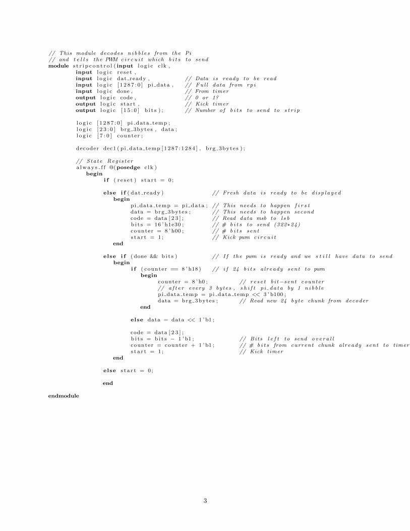
// This module decodes n i b b l e s from the Pi// and t e l l s the PWM c i r c u i t which b i t s to sendmodule s t r i p c o n t r o l ( input l o g i c c lk ,
input l o g i c r e s e t ,input l o g i c dat ready , // Data i s ready to be readinput l o g i c [ 1 2 8 7 : 0 ] p i data , // Fu l l data from rp iinput l o g i c done , // From timeroutput l o g i c code , // 0 or 1?output l o g i c s ta r t , // Kick t imeroutput l o g i c [ 1 5 : 0 ] b i t s ) ; // Number o f b i t s to send to s t r i p
l o g i c [ 1 2 8 7 : 0 ] p i data temp ;l o g i c [ 2 3 : 0 ] brg 3bytes , data ;l o g i c [ 7 : 0 ] counter ;
decoder dec1 ( pi data temp [ 1 2 8 7 : 1 2 8 4 ] , b rg 3bytes ) ;
// Sta te Reg i s t e ra lway s f f @(posedge c l k )
begini f ( r e s e t ) s t a r t = 0 ;
else i f ( dat ready ) // Fresh data i s ready to be d i s p l a y edbegin
pi data temp = pi data ; // This needs to happen f i r s tdata = brg 3bytes ; // This needs to happen secondcode = data [ 2 3 ] ; // Read data msb to l s bb i t s = 16 ’ h1e30 ; // # b i t s to send (322⇤24)counter = 8 ’ h00 ; // # b i t s sents t a r t = 1 ; // Kick pwm c i r c u i t
end
else i f ( done && b i t s ) // I f the pwm i s ready and we s t i l l have data to sendbegin
i f ( counter == 8 ’ h18 ) // i f 24 b i t s a l ready sent to pwmbegin
counter = 8 ’ h0 ; // r e s e t b i t�sent counter// a f t e r every 3 bytes , s h i f t p i da t a by 1 n i b b l epi data temp = pi data temp << 3 ’ b100 ;data = brg 3bytes ; // Read new 24 by te chunk from decoder
end
else data = data << 1 ’ b1 ;
code = data [ 2 3 ] ;b i t s = b i t s � 1 ’ b1 ; // Bi t s l e f t to send o v e r a l lcounter = counter + 1 ’ b1 ; // # b i t s from current chunk a l ready sent to t imers t a r t = 1 ; // Kick t imer
end
else s t a r t = 0 ;
end
endmodule
3
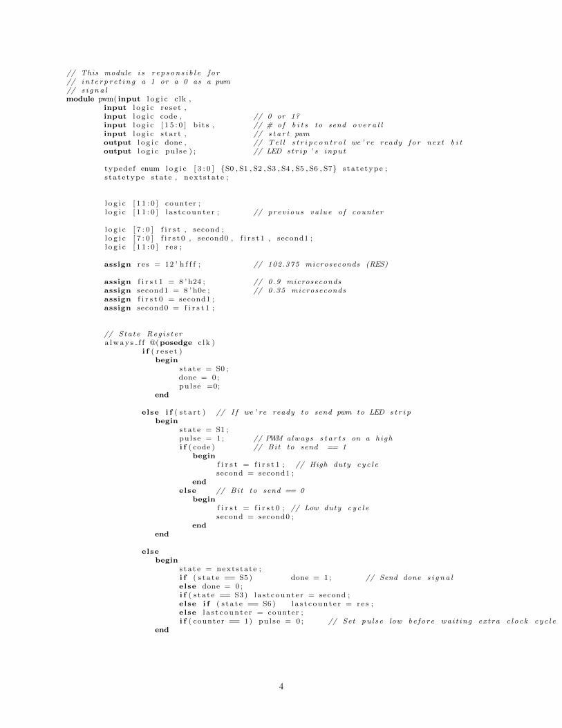
// This module i s r e p s on s i b l e f o r// i n t e r p r e t i n g a 1 or a 0 as a pwm// s i g n a lmodule pwm( input l o g i c c lk ,
input l o g i c r e s e t ,input l o g i c code , // 0 or 1?input l o g i c [ 1 5 : 0 ] b i t s , // # of b i t s to send o v e r a l linput l o g i c s ta r t , // s t a r t pwmoutput l o g i c done , // Te l l s t r i p c o n t r o l we ’ re ready f o r next b i toutput l o g i c pu l s e ) ; // LED s t r i p ’ s input
typede f enum l o g i c [ 3 : 0 ] {S0 , S1 , S2 , S3 , S4 , S5 , S6 , S7} s t a t e type ;s t a t e type s tate , n ex t s t a t e ;
l o g i c [ 1 1 : 0 ] counter ;l o g i c [ 1 1 : 0 ] l a s t c oun t e r ; // prev ious va lue o f counter
l o g i c [ 7 : 0 ] f i r s t , second ;l o g i c [ 7 : 0 ] f i r s t 0 , second0 , f i r s t 1 , second1 ;l o g i c [ 1 1 : 0 ] r e s ;
assign r e s = 12 ’ h f f f ; // 102.375 microseconds (RES)
assign f i r s t 1 = 8 ’ h24 ; // 0.9 microsecondsassign second1 = 8 ’ h0e ; // 0.35 microsecondsassign f i r s t 0 = second1 ;assign second0 = f i r s t 1 ;
// Sta te Reg i s t e ra lway s f f @(posedge c l k )
i f ( r e s e t )begin
s t a t e = S0 ;done = 0 ;pu l s e =0;
end
else i f ( s t a r t ) // I f we ’ re ready to send pwm to LED s t r i pbegin
s t a t e = S1 ;pu l s e = 1 ; // PWM always s t a r t s on a highi f ( code ) // Bit to send == 1
beginf i r s t = f i r s t 1 ; // High duty cy c l esecond = second1 ;
endelse // Bit to send == 0
beginf i r s t = f i r s t 0 ; // Low duty cy c l esecond = second0 ;
endend
elsebegin
s t a t e = nex t s t a t e ;i f ( s t a t e == S5 ) done = 1 ; // Send done s i g n a lelse done = 0 ;i f ( s t a t e == S3 ) l a s t c oun t e r = second ;else i f ( s t a t e == S6 ) l a s t c oun t e r = r e s ;else l a s t c oun t e r = counter ;i f ( counter == 1) pu l s e = 0 ; // Set pu l s e low be f o r e wa i t ing ex t ra c l o c k c y c l e
end
4
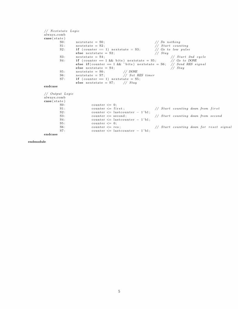
// Nex t s ta t e Logicalways combcase ( s t a t e )
S0 : n ex t s t a t e = S0 ; // Do nothingS1 : nex t s t a t e = S2 ; // S ta r t count ingS2 : i f ( counter == 1) nex t s t a t e = S3 ; // Go to low pu l s e
else nex t s t a t e = S2 ; // StayS3 : nex t s t a t e = S4 ; // S ta r t 2nd cy c l eS4 : i f ( counter == 1 && b i t s ) nex t s t a t e = S5 ; // Go to DONE
else i f ( counter == 1 && ˜ b i t s ) nex t s t a t e = S6 ; // Send RES s i g n a lelse nex t s t a t e = S4 ; // Stay
S5 : nex t s t a t e = S0 ; // DONES6 : nex t s t a t e = S7 ; // Set RES timerS7 : i f ( counter == 1) nex t s t a t e = S5 ;
else nex t s t a t e = S7 ; // Stayendcase
// Output Logicalways combcase ( s t a t e )
S0 : counter <= 0 ;S1 : counter <= f i r s t ; // S ta r t count ing down from f i r s tS2 : counter <= la s t c oun t e r � 1 ’ b1 ;S3 : counter <= second ; // S ta r t count ing down from secondS4 : counter <= la s t c oun t e r � 1 ’ b1 ;S5 : counter <= 0 ;S6 : counter <= re s ; // S ta r t count ing down fo r r e s e t s i g n a lS7 : counter <= la s t c oun t e r � 1 ’ b1 ;
endcase
endmodule
5
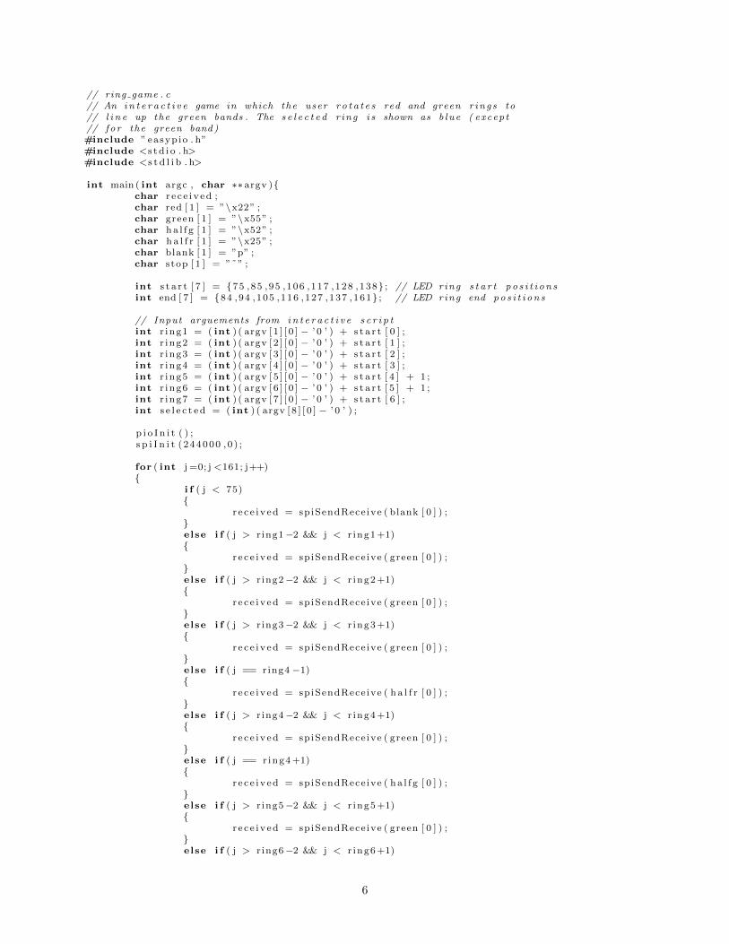
// ring game . c// An i n t e r a c t i v e game in which the user r o t a t e s red and green r ing s to// l i n e up the green bands . The s e l e c t e d r ing i s shown as b lue ( excep t// fo r the green band )#include ” easyp io . h”#include <s t d i o . h>#include <s t d l i b . h>
int main ( int argc , char ⇤⇤ argv ){char r e c e i v ed ;char red [ 1 ] = ”\x22” ;char green [ 1 ] = ”\x55” ;char ha l f g [ 1 ] = ”\x52” ;char h a l f r [ 1 ] = ”\x25” ;char blank [ 1 ] = ”p” ;char stop [ 1 ] = ”˜” ;
int s t a r t [ 7 ] = {75 ,85 ,95 ,106 ,117 ,128 ,138} ; // LED ring s t a r t p o s i t i o n sint end [ 7 ] = {84 ,94 ,105 ,116 ,127 ,137 ,161} ; // LED ring end po s i t i o n s
// Input arguements from i n t e r a c t i v e s c r i p tint r ing1 = ( int ) ( argv [ 1 ] [ 0 ] � ’ 0 ’ ) + s t a r t [ 0 ] ;int r ing2 = ( int ) ( argv [ 2 ] [ 0 ] � ’ 0 ’ ) + s t a r t [ 1 ] ;int r ing3 = ( int ) ( argv [ 3 ] [ 0 ] � ’ 0 ’ ) + s t a r t [ 2 ] ;int r ing4 = ( int ) ( argv [ 4 ] [ 0 ] � ’ 0 ’ ) + s t a r t [ 3 ] ;int r ing5 = ( int ) ( argv [ 5 ] [ 0 ] � ’ 0 ’ ) + s t a r t [ 4 ] + 1 ;int r ing6 = ( int ) ( argv [ 6 ] [ 0 ] � ’ 0 ’ ) + s t a r t [ 5 ] + 1 ;int r ing7 = ( int ) ( argv [ 7 ] [ 0 ] � ’ 0 ’ ) + s t a r t [ 6 ] ;int s e l e c t e d = ( int ) ( argv [ 8 ] [ 0 ] � ’ 0 ’ ) ;
p i o I n i t ( ) ;s p i I n i t ( 244000 , 0 ) ;
for ( int j =0; j <161; j++){
i f ( j < 75){
r e c e i v ed = spiSendRece ive ( blank [ 0 ] ) ;}else i f ( j > r ing1�2 && j < r ing1+1){
r e c e i v ed = spiSendRece ive ( green [ 0 ] ) ;}else i f ( j > r ing2�2 && j < r ing2+1){
r e c e i v ed = spiSendRece ive ( green [ 0 ] ) ;}else i f ( j > r ing3�2 && j < r ing3+1){
r e c e i v ed = spiSendRece ive ( green [ 0 ] ) ;}else i f ( j == ring4 �1){
r e c e i v ed = spiSendRece ive ( h a l f r [ 0 ] ) ;}else i f ( j > r ing4�2 && j < r ing4+1){
r e c e i v ed = spiSendRece ive ( green [ 0 ] ) ;}else i f ( j == r ing4+1){
r e c e i v ed = spiSendRece ive ( ha l f g [ 0 ] ) ;}else i f ( j > r ing5�2 && j < r ing5+1){
r e c e i v ed = spiSendRece ive ( green [ 0 ] ) ;}else i f ( j > r ing6�2 && j < r ing6+1)
6
{r e c e i v ed = spiSendRece ive ( green [ 0 ] ) ;
}
else i f ( j == ring7 �1){
r e c e i v ed = spiSendRece ive ( h a l f r [ 0 ] ) ;}else i f ( j > r ing7�2 && j < r ing7+1){
r e c e i v ed = spiSendRece ive ( green [ 0 ] ) ;i f ( j == r ing7 ){
r e c e i v ed = spiSendRece ive ( ha l f g [ 0 ] ) ;}
}else i f ( j > 75){
i f ( j > s t a r t [ s e l e c t e d ] && j < s t a r t [ s e l e c t e d ] ) {r e c e i v ed = spiSendRece ive ( blue [ 0 ] )
}else {
r e c e i v ed = spiSendRece ive ( red [ 0 ] ) ;}
}}r e c e i v ed = spiSendRece ive ( stop [ 0 ] ) ;
return 0 ;}
7
// menu . c// A swir l y , c o l o r f u l d i s p l a y to repre sen t the orb ’ s menu .// This program u t i l i z e s a 3D repre s en ta t i on o f v e c t o r s// to map out the po s i t i on o f each LED on the orb , and c a l c u l a t e s// a master vec to r about which symmetrical d i s p l a y s can be made .// Idea c r e d i t s to Alex Go lds te in .#include <s t d i o . h>#include <math . h>#include <time . h>#include ” easyp io . h”
#define SPHERE RADIUS 6 .0 // inches#define LED INTERVAL 1.28 // inches#define PI 3.14159265359
#define X DIR 0#define Y DIR 1
#define XNUM 7 // # r ing sconst f loat X OFFSETS[XNUM] = {0 ,0 , 0 , 0 , 0 , 0 , 0} ;const f loat X ERRORS[XNUM] = { 0 . 0 , 0 . 0 , 0 . 0 , 0 . 0 , 0 . 0 , 0 . 0 , 0 . 0 } ; // Compensate f o r hardware i s s u e sconst int X LENGTHS[XNUM] = {18 , 22 , 22 ,24 ,24 , 20 , 18} ; // # LEDs in each r ing
#define YNUM 7 // # r ing sconst f loat Y OFFSETS[YNUM] = {0 ,0 , 0 , 0 , 0 , 0 , 0} ;const f loat Y ERRORS[YNUM] = { 0 . 0 , 0 . 0 , 0 . 0 , 0 . 0 , 0 . 0 , 0 . 0 , 0 . 0 } ; // Compensate f o r hardware i s s u e sconst int Y LENGTHS[YNUM] = {20 , 20 , 22 ,20 ,24 , 20 , 48} ; // # LEDs in r ing
char xLeds [ 7 4 ] ;char yLeds [ 8 7 ] ;
f loat xVectors [ 1 4 8 ] [ 3 ] ;f loat yVectors [ 1 7 4 ] [ 3 ] ;
f loat thetaR ;int numColors ;
// Used to p r e c a l c u l a t e LED vec t o r svoid setLedVec ( f loat o f f s e t , f loat di s tance , int dir , f loat ⇤ retVec ) {
f loat x , y , z ;f loat smal lRadius = s q r t f (SPHERE RADIUS⇤SPHERE RADIUS � o f f s e t ⇤ o f f s e t ) ;f loat theta ;
i f ( d i r == X DIR) {theta = PI + ( d i s t anc e ) / ( 1 . 0⇤ smal lRadius ) ;
}else {
theta = PI � ( d i s t anc e ) / (1 . 0⇤ smal lRadius ) ;}
z = �smal lRadius ⇤ cos ( theta ) ;
i f ( d i r == X DIR) {x = o f f s e t ;y = smal lRadius ⇤ s i n ( theta ) ;
}else {
y = o f f s e t ;x = smal lRadius ⇤ s i n ( theta ) ;
}f loat mag = sq r t ( x⇤x + y⇤y + z⇤z ) ;retVec [ 0 ] = x / mag ;retVec [ 1 ] = y / mag ;retVec [ 2 ] = z / mag ;
}
8
void delay ( int mi l i s ){f loat s t a r t = c l ock ( ) ;while ( c l o ck ( ) < s t a r t + m i l i s ⇤ 1000) ;
}
// Dot Product o f two vec t o r sf loat dotProduct ( f loat ⇤ vec1 , f loat ⇤ vec2 ) {
f loat dotProd = 0 ;int i ;for ( i = 0 ; i < 3 ; i++) {
dotProd += vec1 [ i ]⇤ vec2 [ i ] ;}return dotProd ;
}
// Use normal vec to r to as s i gn des i gns to orbvoid setLedRings ( f loat ⇤ normalVec , char colorSpectrum [ ] , int spectrumLength ) {
char stop = ⇤”˜” ;f loat avg ;
int j = 0 ;for ( int i = 0 ; i < XNUM; i++) {
for ( int l ed = 0 ; l ed < X LENGTHS[ i ] ; l ed++) {i f ( j == 0){
avg = dotProduct ( xVectors [ 0 ] , normalVec ) ;}else {
f loat d i s tance1 = dotProduct ( xVectors [ j �1] , normalVec ) ;f loat d i s tance2 = dotProduct ( xVectors [ j ] , normalVec ) ;avg = ( d i s t ance1 + d i s tance2 ) / 2 ;
}int segment = 0 . 5⇤ ( avg + 1 . 0 )⇤ spectrumLength ;
char c o l o r = colorSpectrum [ segment ] ;i f ( ! ( j %2)){
xLeds [ j /2 ] = co l o r ;}j++;
}}j =0;for ( int i = 0 ; i < YNUM; i++) {for ( int l ed = 0 ; l ed < Y LENGTHS[ i ] ; l ed++) {
i f ( j == 0){avg = dotProduct ( yVectors [ 0 ] , normalVec ) ;
}else {
f loat d i s tance1 = dotProduct ( yVectors [ j �1] , normalVec ) ;f loat d i s tance2 = dotProduct ( yVectors [ j ] , normalVec ) ;avg = ( d i s t ance1 + d i s tance2 ) / 2 ;
}int segment = 0 . 5⇤ ( avg + 1 . 0 )⇤ spectrumLength ;
char c o l o r = colorSpectrum [ segment ] ;i f ( ! ( j %2)){
yLeds [ j /2 ] = co l o r ;}j++;
}}
for ( int i = 0 ; i < 74 ; i++) {char r e c e i v ed = spiSendRece ive ( xLeds [ i ] ) ;
}for ( int i = 0 ; i < 87 ; i++) {
9
char r e c e i v ed = spiSendRece ive ( yLeds [ i ] ) ;}char r e c e i v ed = spiSendRece ive ( stop ) ;
}
void main (void ) {
p i o I n i t ( ) ;s p i I n i t ( 244000 , 0 ) ;int j = 0 ;
// Precompute v e c t o r sfor ( int i = 0 ; i < XNUM; i++) {for ( int l ed = 0 ; l ed < X LENGTHS[ i ] ; l ed++) {
setLedVec (X OFFSETS[ i ] , X ERRORS[ i ] + ( l ed � X LENGTHS[ i ] / 2 ) ⇤ LED INTERVAL, X DIR ,xVectors [ j ] ) ;
j++;}
}j = 0 ;for ( int i = 0 ; i < YNUM; i++) {for ( int l ed = 0 ; l ed < Y LENGTHS[ i ] ; l ed++) {
setLedVec (Y OFFSETS[ i ] , Y ERRORS[ i ] + ( l ed � Y LENGTHS[ i ] / 2 ) ⇤ LED INTERVAL, Y DIR ,yVectors [ j ] ) ;
j++;}
}
f loat normalVec [ 3 ] = {0 , 0 , 1} ;
while(1==1){thetaR += 5 ;normalVec [ 0 ] = s i n ( thetaR /100 . 0 ) ;normalVec [ 1 ] = cos ( thetaR /100 . 0 ) ;normalVec [ 2 ] = 0 ;
char colorSpectrum [ 7 ] = ”\x66\x66\x66\x88\x88\x99\x99” ;setLedRings ( normalVec , colorSpectrum , 7 ) ;de lay ( 1 0 ) ;
}}
10
# f i n a l p r o j e c t . py# E155 � FInal Pro jec t � 2017# ckotcherha@hmc . edu
import enumimport reimport s t r u c timport sysimport timeimport myo raw
from subproces s import c a l l
global LEDupdateCounterglobal modeglobal high l ighted modeglobal num modesglobal r i n g sglobal c y c l e s t o i g n o r eglobal r i ng i ndexLEDupdateCounter = 0mode = 0high l ighted mode = 1num modes = 2r i n g s = [ 1 , 2 , 3 , 4 , 5 , 6 , 7 , 7 ]c y c l e s t o i g n o r e = 0r i ng i ndex = 0
i f name == ’ ma in ’ :
#handles motion data and gamesdef data IMU( quat , acc , gyro , t imes = [ ] ) :
global LEDupdateCounterglobal modeglobal r i n g sglobal c y c l e s t o i g n o r eglobal r i ng i ndexglobal high l ighted modef rame de lay = 5acc x = acc [ 0 ]acc y = acc [ 1 ]a c c z = acc [ 2 ]gyro x = gyro [ 0 ]gyro y = gyro [ 1 ]gyro z = gyro [ 2 ]
#LED update de lay ( a l l game modes )LEDupdateCounter += 1i f LEDupdateCounter > f rame de lay : #re s e t count
LEDupdateCounter = 0
i f mode == 1 : #spectrum he i gh t modei f ( acc x <�1500):
i f LEDupdateCounter == frame de lay :print ( ’magenta ’ )c a l l ( [ ” sudo” , ” . . / p r o j e c t /magenta” ] )
e l i f ( acc x <�1000):i f LEDupdateCounter == frame de lay :
print ( ’ v i o l e t ’ )c a l l ( [ ” sudo” , ” . . / p r o j e c t / v i o l e t ” ] )
e l i f ( acc x <�500):i f LEDupdateCounter == frame de lay :
print ( ’ b lue ’ )c a l l ( [ ” sudo” , ” . . / p r o j e c t / blue ” ] )
e l i f ( acc x <0):i f LEDupdateCounter == frame de lay :
print ( ’ i nd i go ’ )c a l l ( [ ” sudo” , ” . . / p r o j e c t / ind igo ” ] )
11
e l i f ( acc x <500):i f LEDupdateCounter == frame de lay :
print ( ’ green ’ )c a l l ( [ ” sudo” , ” . . / p r o j e c t / green ” ] )
e l i f ( acc x <1000):i f LEDupdateCounter == frame de lay :
print ( ’ ye l low ’ )c a l l ( [ ” sudo” , ” . . / p r o j e c t / ye l low ” ] )
e l i f ( acc x <1500):i f LEDupdateCounter == frame de lay :
print ( ’ orange ’ )c a l l ( [ ” sudo” , ” . . / p r o j e c t / orange ” ] )
e l i f ( acc x <2054):i f LEDupdateCounter == frame de lay :
print ( ’ red ’ )c a l l ( [ ” sudo” , ” . . / p r o j e c t / red ” ] )
else :i f LEDupdateCounter == frame de lay :
print ( ’ c l e a r ’ )c a l l ( [ ” sudo” , ” . . / p r o j e c t / c l e a r ” ] )
i f mode == 2 : #ring game#check f o r v i c t o r y condi t ion , prevent movement ( base case )i f ( r i n g s [ 0 : 7 ] == [ 5 , 5 , 5 , 5 , 5 , 5 , 5 ] ) :
c a l l ( [ ” sudo” , ” . . / p r o j e c t /magenta” ] )c a l l ( [ ” sudo” , ” . . / p r o j e c t / v i o l e t ” ] )c a l l ( [ ” sudo” , ” . . / p r o j e c t / blue ” ] )c a l l ( [ ” sudo” , ” . . / p r o j e c t / ind igo ” ] )c a l l ( [ ” sudo” , ” . . / p r o j e c t / green ” ] )c a l l ( [ ” sudo” , ” . . / p r o j e c t / ye l low ” ] )c a l l ( [ ” sudo” , ” . . / p r o j e c t / orange ” ] )c a l l ( [ ” sudo” , ” . . / p r o j e c t / red ” ] )c a l l ( [ ” sudo” , ” . . / p r o j e c t / c l e a r ” ] )mode = 0 #ex i t to menu#f i r s t menu opt ionhigh l ighted mode = 1print ( ’ r e tu rn ing to menu ’ )c a l l ( [ ” sudo” , ” . . / p r o j e c t / ind igo ” ] )print ( ’ Spectum Height Mode ’ )
#otherwise , manipulate r ing o r i en t a t i on selse :
i f LEDupdateCounter == frame de lay :#i n i t i a l d e l t a va lue so r i en t a t i on change = 0r ing change = 0
#cyc l e counter f o r i gnor ing datac y c l e s t o i g n o r e �= 1i f c y c l e s t o i g n o r e < 0 : #re s e t count
c y c l e s t o i g n o r e = 0
i f c y c l e s t o i g n o r e == 0 : #don ’ t check i f recent d e t e c t i on#check f o r p i tch�tw i t ch to s h i f t s e l e c t e d r ingi f acc x < �2000:
r ing change = 1 #s h i f t upo r i en t a t i on change = 0c y c l e s t o i g n o r e = 3print ( ’+1 up ’ )
e l i f acc x > 1700 :r ing change = �1 #s h i f t downo r i en t a t i on change = 0c y c l e s t o i g n o r e = 3print ( ’�1 down ’ )
else :r ing change = 0#check fo r r o l l�tw i t ch to s h i f t subr ing va lue
12
i f gyro x < �5400: #neg i s r i g h to r i en t a t i on change = �1 #s h i f t r i g h tc y c l e s t o i g n o r e = 3print ( ’�1 r i gh t ’ )
e l i f gyro x > 3300 :o r i en t a t i on change = 1 #s h i f t l e f tc y c l e s t o i g n o r e = 3print ( ’+1 l e f t ’ )
else :o r i en t a t i on change = 0
#Update s e l e c t e d r ing va lue s :r i ng i ndex += r ing change #update s e l e c t e d r ing#l im i t r ing index ing rangefor i in range (0 , len ( r i n g s ) ) :
i f r i ng i ndex < 0 :r i ng i ndex = 0
i f r i ng i ndex > 6 :r i ng i ndex = 6
#f i n a l l y , g i v e s e l e c t e d r ing updated va luer i n g s [ r i n g i ndex ] += or i en ta t i on change#l im i t subr ing l e d va lue rangei f r i n g s [ r i n g i ndex ] < 1 :
r i n g s [ r i n g i ndex ] = 1e l i f r i n g s [ r i n g i ndex ] > 8 :
r i n g s [ r i n g i ndex ] = 8
print ( r i n g s )#update LED r ing sc a l l ( [ ” sudo” , ” . . / p r o j e c t / ring game” , str ( r i n g s [ 0 ] ) , str ( r i n g s [ 1 ] ) ,str ( r i n g s [ 2 ] ) , str ( r i n g s [ 3 ] ) , str ( r i n g s [ 4 ] ) , str ( r i n g s [ 5 ] ) ,str ( r i n g s [ 6 ] ) , str ( r i ng i ndex ) ] )
def data Pose (p ) :global modeglobal high l ighted modeglobal num modesglobal r i n g s
#MENU mode (0)i f mode == 0 :
#determine h i g h l i g h t i n gi f high l ighted mode == 1 : #spectrum h i gh t mode
c a l l ( [ ” sudo” , ” . . / p r o j e c t / ind igo ” ] )print ( ’ Spectum Height Mode ’ )
e l i f high l ighted mode == 2 : #ring game modec a l l ( [ ” sudo” , ” . . / p r o j e c t / green ” ] )print ( ’ Ring Game Mode ’ )
else : #shouldn ’ t happen ,c a l l ( [ ” sudo” , ” . . / p r o j e c t / ind igo ” ] )h igh l ighted mode == 1
#check fo r h i g h l i g h t i n g swi t chi f p == Pose .WAVEOUT: #h i g h l i g h t next mode
high l ighted mode +=1i f high l ighted mode > num modes : #wrap around
high l ighted mode = 1i f p == Pose .WAVE IN: #h i g h l i g h t prev ious mode
high l ighted mode �=1i f high l ighted mode < 1 : #wrap around
high l ighted mode = num modesi f p == Pose . FIST : #ENTER h i g h l i g h t e d mode
print ( ’ENTER mode : ’ , h igh l ighted mode )mode = high l ighted mode #leave menu , ENTER h i g h l i g h t e d mode
13
i f mode == 2 : #s t a r t i n g r ing o r e i n t a t i on sr i n g s = [ 1 , 3 , 6 , 2 , 4 , 8 , 6 , 7 ]
#when not in menu ( in a game mode) , check f o r EXIT to menue l i f p == Pose .WAVE IN:
print ( ’EXIT to menu ’ )mode = 0
m = MyoRaw( sys . argv [ 1 ] i f len ( sys . argv ) >= 2 else None ) #n i t i a l i z e Myo o b j e c tm. connect ( ) #connect to Myo
m. add imu handler ( data IMU) #i n i t i a l i z e IMU handler , motion proces s ingm. add pose hand le r ( data Pose ) #menu and game s t a t e con t ro l
try :while True :
m. run (1 )
except KeyboardInterrupt :pass
f ina l ly :m. d i s connec t ( )print ( ’ d i s connected ’ )
14