Embed Size (px)
DESCRIPTION
ZTE GSM
Citation preview

Internal Use Only▲
Application of ZXG10 BSS Power Control Algorithms
Special Subject Guidebook
Version: V1.0
Released by:
GSM Network Planning & Optimization Dept.
Engineering Service Division
ZTE Corporation
This document contains proprietary information of ZTE Corporation and is not to be disclosed or used
except in accordance with applicable agreements.
Internal Use Only▲
GSM Network Planning & Optimization Dept.
Special Subject Guidebook
Version introduction:
Versio
n
Date Writer Assessor Translator Amendment records
V1.
0
2009-05-
12
Chang
HaiJjie
Zheng
Hao
None
V1.
0
2009-05-
26
Chang
HaiJjie
Zheng
Hao
Feng XiaoYing Parameters and application
scenarios were added; figure
description of some
problems was added.
This document contains proprietary information of ZTE Corporation and is not to be disclosed or used
except in accordance with applicable agreements.
Internal Use Only▲
Key words:
Power control algorithms, Application of algorithms
Abstract:
This guidebook mainly introduces ZTE power control algorithms and the application of
these algorithms.
References:
《Preprocessing of FUC and Design of Power Control Module in ZXG10-BTS(V2)》
《Training Materials of Power Control》
《Power Control Adjustment Scheme》
《BTSV6.20.102e Power Control Guidebook》
This document contains proprietary information of ZTE Corporation and is not to be disclosed or used
except in accordance with applicable agreements.
Internal Use Only▲
Contents
1 Overview.............................................................................................................................................1
2 Features of Power Control................................................................................................................2
3 Application Scenario of Power Control...........................................................................................3
4 Theories of Power Control................................................................................................................4
4.1 Location of power control module in the system............................................................................4
4.2 Overall flow of CS power control...................................................................................................5
4.3 Descriptions of power control process............................................................................................7
4.3.1 Storage of measurement data.................................................................................................7
4.3.2 Calculation of averages.........................................................................................................7
4.3.3 Window, average and threshold...........................................................................................10
4.3.4 Power control step size........................................................................................................12
4.3.5 Performance measurement..................................................................................................14
4.3.6 Power control indication......................................................................................................14
4.4 Improvement on power control algorithms...................................................................................14
4.4.1 Comparison of algorithms before/after improvement..........................................................14
4.4.2 Initial state of power control................................................................................................15
4.4.3 UL level and quality decision, step size..............................................................................16
4.4.4 Power rank control..............................................................................................................18
4.4.5 Conversion of power control states.....................................................................................20
4.4.6 Clear MR queues and counters............................................................................................21
4.5 PS power control theories.............................................................................................................22
5 CS Power Control Parameters & Reference Values.....................................................................26
5.1 Uplink /downlink power control...................................................................................................26
5.2 Received signal level & quality threshold.....................................................................................26
5.2.1 Received signal level...........................................................................................................27
5.2.2 Received signal quality........................................................................................................27
This document contains proprietary information of ZTE Corporation and is not to be disclosed or used
except in accordance with applicable agreements. I

Internal Use Only▲
5.3 Power control period.....................................................................................................................29
5.3.1 Sample count(window)& Weight(weight)................................................................29
5.3.2 Number of power control samples N & P...........................................................................29
5.4 Power adjustment step..................................................................................................................30
5.5 Criteria of power control state conversion-N1, N2.......................................................................31
5.6 Max power rank of MS & BTS for initial access..........................................................................31
5.7 Rapid power control......................................................................................................................32
5.8 Fast averaging...............................................................................................................................33
5.9 Setting of power control parameters.............................................................................................34
6 Setting of Power Control Parameters in Different Scenarios......................................................36
6.1 Setting of signal quality threshold (under poor DL radio environment).......................................36
6.2 Setting of uplink/downlink power control period.........................................................................36
6.3 Handover threshold.......................................................................................................................37
6.4 Highway/ railway..........................................................................................................................37
6.5 Building........................................................................................................................................37
7 Examples of Power Control...............................................................................................................38
This document contains proprietary information of ZTE Corporation and is not to be disclosed or used
except in accordance with applicable agreements. II
Internal Use Only▲
1 Overview
Power control is divided into static power control and dynamic power control. Static
power control is to restrict the max transmitting power of MS or BTS; dynamic power
control is for the network to dynamically decide the max transmitting power of MS or
BTS according to radio environment around subscribers. The power control discussed
in this manual belongs to the scope of dynamic power control.
The main function of power control is to optimize the transmitting power of MS and
BTS without affecting radio transmission quality, so as to improve frequency efficiency
as well as reducing the average transmitting power of MS and BTS, and to reduce
interference to other communications. In mobile systems, to reduce interference means
to have high spectrum efficiency, which means increase of capacity. In the system,
power control of uplink and downlink is independent to each other. MS power control
is to adjust the output power of MS, so that BTS can get stable receive signal level,
interference from other MS using the same channel will be restricted, MS power
consumption will be lowered, and MS average useful time will be extended; BTS
power control is to make MS get stable receive signal level, to restrict interference
from MS using the same channel, and to lower BTS power consumption.
This document contains proprietary information of ZTE Corporation and is not to be disclosed or used
except in accordance with applicable agreements. 1
Internal Use Only▲
2 Features of Power Control
According to the amount of measurement data, power control makes weighted average
of the data respectively, then compares the averages with corresponding thresholds, and
then makes MS and BTS power control according to result of the comparison. In order
to meet requirements of power control speed on site, ZTE provides fast averaging,
rapid power control, etc. to accelerate power control speed.
Uplink and downlink power control is performed separately.
CS and PS power control is performed separately.
In Version 6.20.101e and the subsequent versions, dynamic power control algorithms
have been optimized. Having combined the speed and stability of power control, power
control is divided into two states: initial state and stable state. Initial state is to adjust
power to the proper level; stable state is to prevent frequent adjustment of frequency, so
as to keep power output stable.
This document contains proprietary information of ZTE Corporation and is not to be disclosed or used
except in accordance with applicable agreements. 2
Internal Use Only▲
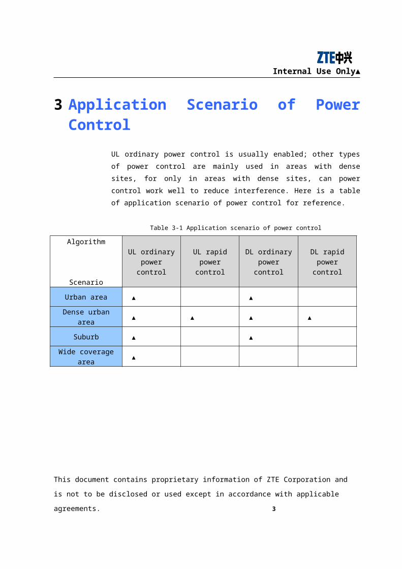
3 Application Scenario of Power Control
UL ordinary power control is usually enabled; other types of power control are mainly
used in areas with dense sites, for only in areas with dense sites, can power control
work well to reduce interference. Here is a table of application scenario of power
control for reference.
Table 3-1 Application scenario of power control
Algorithm
Scenario
UL ordinary power control
UL rapid power control
DL ordinary power control
DL rapid power control
Urban area ▲ ▲
Dense urban area ▲ ▲ ▲ ▲
Suburb ▲ ▲
Wide coverage area
▲
This document contains proprietary information of ZTE Corporation and is not to be disclosed or used
except in accordance with applicable agreements. 3
Internal Use Only▲
4 Theories of Power Control
4.1 Location of power control module in the system
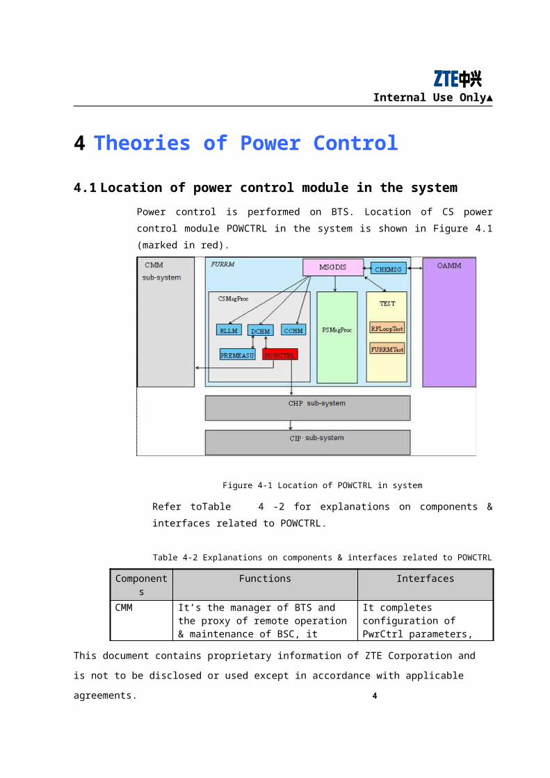
Power control is performed on BTS. Location of CS power control module POWCTRL in
the system is shown in Figure 4.1 (marked in red).
Figure 4-1 Location of POWCTRL in system
Refer toTable 4-2 for explanations on components & interfaces related to POWCTRL.
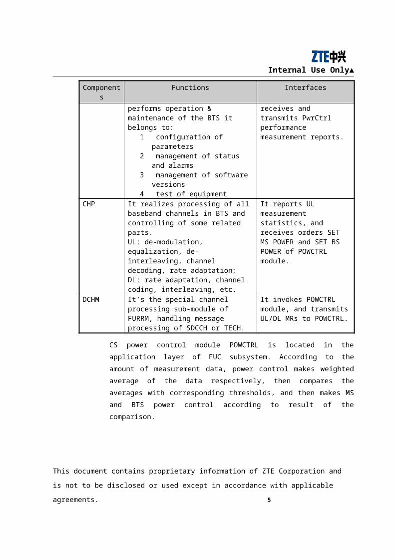
Table 4-2 Explanations on components & interfaces related to POWCTRL
Components Functions Interfaces
CMM It’s the manager of BTS and the proxy of remote operation & maintenance of BSC, it performs operation & maintenance of the BTS it belongs to:
① configuration of parameters② management of status and alarms③ management of software versions④ test of equipment
It completes configuration of PwrCtrl parameters, receives and transmits PwrCtrl performance measurement reports.
CHP It realizes processing of all baseband channels in BTS and controlling of some related parts.
It reports UL measurement statistics, and receives orders SET MS POWER and SET BS
This document contains proprietary information of ZTE Corporation and is not to be disclosed or used
except in accordance with applicable agreements. 4
Internal Use Only▲
Components Functions Interfaces
UL: de-modulation, equalization, de-interleaving, channel decoding, rate adaptation;DL: rate adaptation, channel coding, interleaving, etc.
POWER of POWCTRL module.
DCHM It’s the special channel processing sub-module of FURRM, handling message processing of SDCCH or TECH.
It invokes POWCTRL module, and transmits UL/DL MRs to POWCTRL.
CS power control module POWCTRL is located in the application layer of FUC
subsystem. According to the amount of measurement data, power control makes
weighted average of the data respectively, then compares the averages with
corresponding thresholds, and then makes MS and BTS power control according to
result of the comparison.
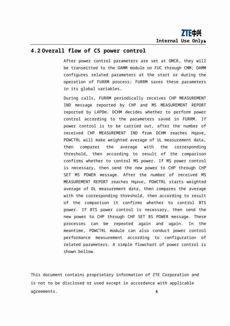
4.2 Overall flow of CS power control
After power control parameters are set at OMCR, they will be transmitted to the
OAMM module on FUC through CMM; OAMM configures related parameters at the
start or during the operation of FURRM process; FURRM saves these parameters in its
global variables.
During calls, FURRM periodically receives CHP MEASUREMENT IND message
reported by CHP and MS MEASUREMENT REPORT reported by LAPDm. DCHM
decides whether to perform power control according to the parameters saved in
FURRM. If power control is to be carried out, after the number of received CHP
MEASUREMENT IND from DCHM reaches Hqave, POWCTRL will make weighted
average of UL measurement data, then compares the average with the corresponding
threshold, then according to result of the comparison confirms whether to control MS
power. If MS power control is necessary, then send the new power to CHP through
CHP SET MS POWER message. After the number of received MS MEASUREMENT
REPORT reaches Hqave, POWCTRL starts weighted average of DL measurement
data, then compares the average with the corresponding threshold, then according to
result of the comparison it confirms whether to control BTS power. If BTS power
control is necessary, then send the new power to CHP through CHP SET BS POWER
message. These processes can be repeated again and again. In the meantime,
This document contains proprietary information of ZTE Corporation and is not to be disclosed or used
except in accordance with applicable agreements. 5
Internal Use Only▲
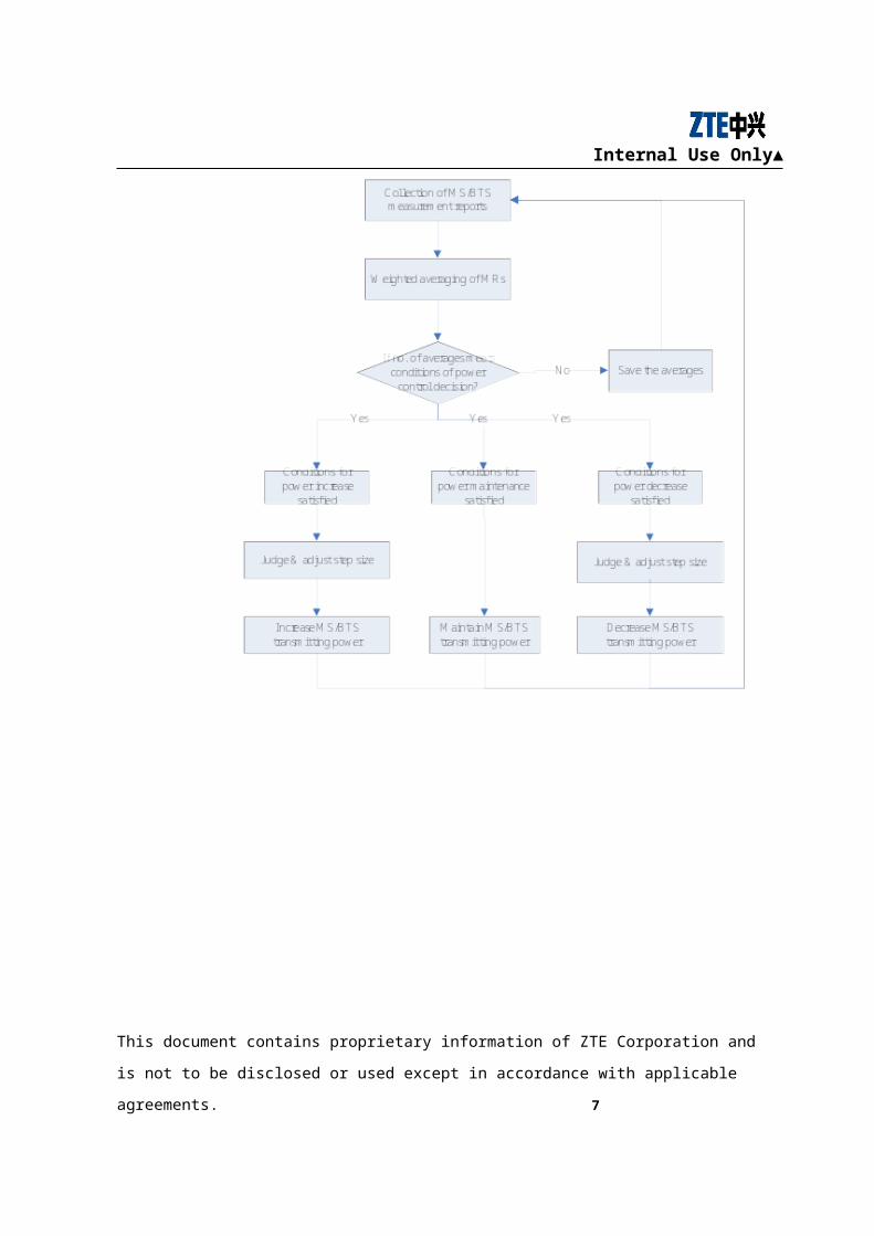
POWCTRL module can also conduct power control performance measurement
according to configuration of related parameters. A simple flowchart of power control
is shown bellow.
This document contains proprietary information of ZTE Corporation and is not to be disclosed or used
except in accordance with applicable agreements. 6
Internal Use Only▲
Figure 4-2 Simple flowchart of power control
4.3 Descriptions of power control process
4.3.1 Storage of measurement data
MR data are saved in the circular table structured with arrays. When the circular table
is filled with data for the first time, new MR data will cover the old data. We can use a
counter to record the number of received MRs, and get the location of latest MR data in
the table. The counter will be refreshed after power control is completed successfully,
and won’t be started until next power control (a certain number PCMinInterval of MRs
in the process will be abandoned; and a certain number PCMinInterval of MRs at the
beginning of the process will also be abandoned, because the first several MRs are not
accurate at the beginning of channel activation). Measurement data and averages of
uplink and downlink are stored separately. According to protocol 05.08, the number of
measurement data and averages of uplink and downlink can at most reach 32.
4.3.2 Calculation of averages
We make weighted average but not the simple averaging calculation of MRs, because
non-consecutive transmission (DTX) exists. In order to increase MR weight when
DTX is off, we can set the weight to be 1 when DTX is on; the weight of DTX Off can
be set at OMCR. These averages are saved in the circular arrays, and use of the data is
controlled by counters. When fast averaging is adopted, the first average is the first
datum, the second average is calculated from the first and the second data, and so on. If
rapid isn’t adopted, the first average is obtained only when the number of data reaches
Hqave.
Suppose the number of MRs in the window is n during DTX Off, receive signal level is
Levoff; and the number of MRs in the window is m during DTX On, and receive signal
level is Levon:
Sum of receive levels is=∑Levoff*Weight+∑Levon*1;
Weighted average=Sum/(n*weight+m*1).
This document contains proprietary information of ZTE Corporation and is not to be disclosed or used
except in accordance with applicable agreements. 7
Internal Use Only▲
For example, the current window size is 3, its weight is 2; take receive signal level as
an example, the levels reported by the three MRs are -80dBm( DTX off), -
70dBm(DTX on),-82dBm(DTX off);
Weighted average=[(-80)*2+(-82)*2+(-70)*1]/(2+2+1)=-78.8dBm
Comparison of ordinary averaging and fast averaging is shown bellow:
This document contains proprietary information of ZTE Corporation and is not to be disclosed or used
except in accordance with applicable agreements. 8
Internal Use Only▲
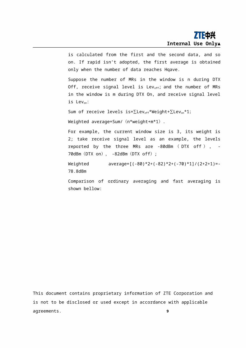
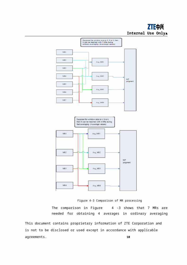
Figure 4-3 Comparison of MR processing
The comparison in Figure 4-3 shows that 7 MRs are needed for obtaining 4 averages in
ordinary averaging process, while only 4 MRs are needed in fast averaging process.
This document contains proprietary information of ZTE Corporation and is not to be disclosed or used
except in accordance with applicable agreements. 9
Internal Use Only▲
4.3.3 Window, average and threshold
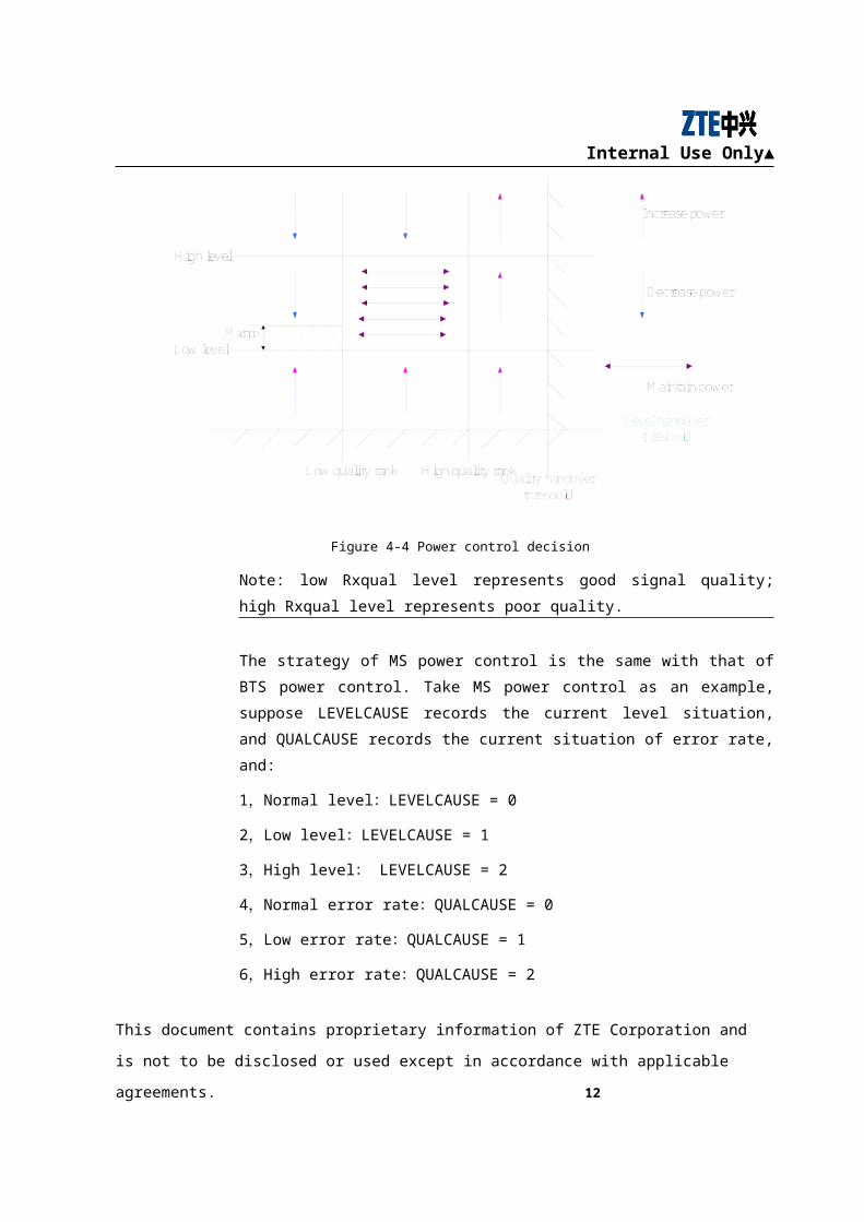
Power control decision can be made according to the status of MS/BTS signal level
and quality. As shown in the following figure, lower signal Rxqual level on the
horizontal ordinate leads to lower signal error rate and better signal quality. For
example, when the receive signal level and quality values are within the range of
corresponding thresholds, the result of power control decision is not to make power
control adjustment; when the receive signal level value is lower than corresponding
threshold, and the receive signal quality is within the range of corresponding threshold,
the power control decision result is to increase power due to level; when the receive
signal level is higher than the “High level”, and receive signal quality is higher than the
“High Rxqual level”, the power control decision result is to increase power due to
quality.
When setting receive signal level and quality thresholds, we must pay attention to the
relation between power control threshold and handover threshold. The low level
threshold of power control must be larger than level handover threshold, while the high
quality threshold of power control must be smaller than quality handover threshold, as
the stripped area shown in Figure 4-4.
This document contains proprietary information of ZTE Corporation and is not to be disclosed or used
except in accordance with applicable agreements. 10
Internal Use Only▲
Figure 4-4 Power control decision
Note: low Rxqual level represents good signal quality; high Rxqual level represents
poor quality.
The strategy of MS power control is the same with that of BTS power control. Take
MS power control as an example, suppose LEVELCAUSE records the current level
situation, and QUALCAUSE records the current situation of error rate, and:
1,Normal level:LEVELCAUSE = 0
2,Low level:LEVELCAUSE = 1
3,High level: LEVELCAUSE = 2
4,Normal error rate:QUALCAUSE = 0
5,Low error rate:QUALCAUSE = 1
6,High error rate:QUALCAUSE = 2
Suppose the level rank is from 0 to 63 (low to high), L_RXLEV is tending to be 0, U_RXLEV is tending to
be 63; error rate class (0~7) represents signal quality (high to low), L_RXQUAL is tending to be 7,
U_RXQUAL is tending to be 0. The average of UL measurement data and corresponding threshold values
and the comparison between them area as follows:
This document contains proprietary information of ZTE Corporation and is not to be disclosed or used
except in accordance with applicable agreements. 11
Internal Use Only▲
If at least a certain number PCULIncrLevP among a certain number PCULIncrLevN of
RXLEV_UL are lower than the low limit L_RXLEV_UL, LEVELCAUSE = 1;
If at least a certain number PCULDecrLevP among a certain number PCULDecrLev of
RXLEV_UL are higher than the high limit U_RXLEV_UL, LEVELCAUSE = 2;
For other situations, LEVELCAUSE =0
(1) If at least a certain number PCULDecrQualP among a certain number
PCULDecrQualN of RXQUAL_UL are lower than the high limit
U_RXQUAL_UL, QUALCAUSE=1;
(2) If at least a certain number PCULIncrQualP among a certain number
PCULIncrQualN of RXQUAL_UL are higher than the low limit
L_RXQUAL_UL, QUALCAUSE=2;
(3) For other situations, QUALCAUSE=0
Compassion of DL data is similar to the description above, just the eight parameters are
marked with DL, like PCDLIncrLevN.
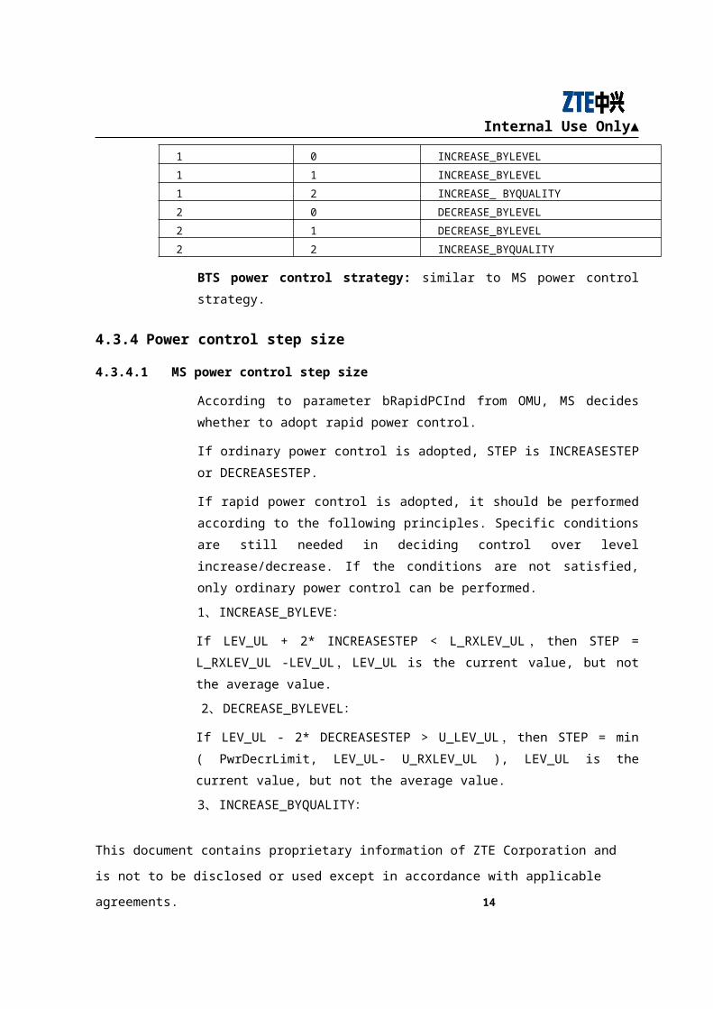
Table 4-3 MS power control strategy
LEVELCAUSE QUALCAUSE Conclusion
0 0 MS_POWER_STAY
0 1 DECREASE_BYQUALITY
0 2 INCREASE_BYQUALITY
1 0 INCREASE_BYLEVEL
1 1 INCREASE_BYLEVEL
1 2 INCREASE_ BYQUALITY
2 0 DECREASE_BYLEVEL
2 1 DECREASE_BYLEVEL
2 2 INCREASE_BYQUALITY
BTS power control strategy: similar to MS power control strategy.
4.3.4 Power control step size
4.3.4.1 MS power control step size
According to parameter bRapidPCInd from OMU, MS decides whether to adopt rapid
power control.
This document contains proprietary information of ZTE Corporation and is not to be disclosed or used
except in accordance with applicable agreements. 12
Internal Use Only▲
If ordinary power control is adopted, STEP is INCREASESTEP or DECREASESTEP.
If rapid power control is adopted, it should be performed according to the following
principles. Specific conditions are still needed in deciding control over level
increase/decrease. If the conditions are not satisfied, only ordinary power control can
be performed.
1、 INCREASE_BYLEVE:
If LEV_UL + 2* INCREASESTEP < L_RXLEV_UL,then STEP = L_RXLEV_UL -
LEV_UL,LEV_UL is the current value, but not the average value.
2、 DECREASE_BYLEVEL:
If LEV_UL - 2* DECREASESTEP > U_LEV_UL,then STEP = min ( PwrDecrLimit,
LEV_UL- U_RXLEV_UL ), LEV_UL is the current value, but not the average value.
3、 INCREASE_BYQUALITY:
If LEV_UL + 2* INCREASESTEP < L_RXLEV_UL
STEP = max ( (1+max(0,Qa)) * INCREASESTEP , L_RXLEV_UL - LEV_UL )
Or STEP = (1+max(0,Qa)) * INCREASESTEP
Qa = QUAL_UL - L_RXQUAL_UL ; QUAL_UL is the current signal
quality,LEV_UL is the current signal level,and neither of them is the average value.
4、DECREASE_BYQUALITY:
For power decrease caused by signal quality, we should be conservative with the step.
size.
Therefore:
If LEV_UL - 2* DECREASESTEP > U_LEV_UL,
STEP = min ( PwrDecrLimit, LEV_UL – U_ RXLEV_UL, (1 +max(0, Qa) ) *
DECREASESTEP); or STEP = DECREASESTEP。
LEV_UL is the current signal level, but not the average value.
Qa = U_RXQUAL_UL – AV_QUAL_UL。
AV_QUAL_UL is the signal quality average.
This document contains proprietary information of ZTE Corporation and is not to be disclosed or used
except in accordance with applicable agreements. 13

Internal Use Only▲
4.3.4.2 BTS power control step size
The calculation and adjustment of BTS power control step size is the same as that of
MS, only change UL in parameters to DL.
4.3.5 Performance measurement
During BTS power control, it needs to report related performance data to BSC, and all
the statistical data is stored in PowerMeasData.
4.3.6 Power control indication
In order to optimize handover algorithms, after power control of MS or BTS, BSC will
be notified the direction (downlink or uplink) of power control by a message POWER
CONTROL IND, and then BSC will clear the corresponding buffer area based on this
message. After each time of power control, the queue of MRs reported will be cleared
to 0. The first average value will not be obtained again until the number of MRs
reported reaches Hqave (non-rapid power control).
4.4 Improvement on power control algorithms
4.4.1 Comparison of algorithms before/after improvement
The existing power control strategy can not simultaneously satisfy the following
situations: 1) make rapid power control of MS, and make MS UL level and quality
meet requirements in the shortest time; 2) after required UL level and quality are
satisfied, MS power control can perform stably, and no adjustment of power is needed
only because of one or two minor problems.
The improved power control algorithm: power control falls into two states—initial
state and stable state. Power control is carried out in over channels. The initialization of
channel power control status is initial state. After a number of power controls, MS UL
level and quality satisfy the expected values, the channel power control status enters
stable state, and it remains in stable state until the channel is released, and then the
status returns to initial state.
This document contains proprietary information of ZTE Corporation and is not to be disclosed or used
except in accordance with applicable agreements. 14
Internal Use Only▲
4.4.2 Initial state of power control
After MS accesses into channel (SDCCH or TCH), if power control period is too long,
it will bring interference to subscribers using other channels. Therefore, in order to
realize fast control of MS power, we carry out power control decision to every uplink
MR, and make adjustments of MS and BTS power rank to make MS UL level and
quality meet the requirements.
When MS or BTS initially accesses into channels, it transmits signals in the max power
rank. In this case, power control usually tends to decrease MS or BTS transmitting
power, until UL level and quality reach the expected values and enter stable state.
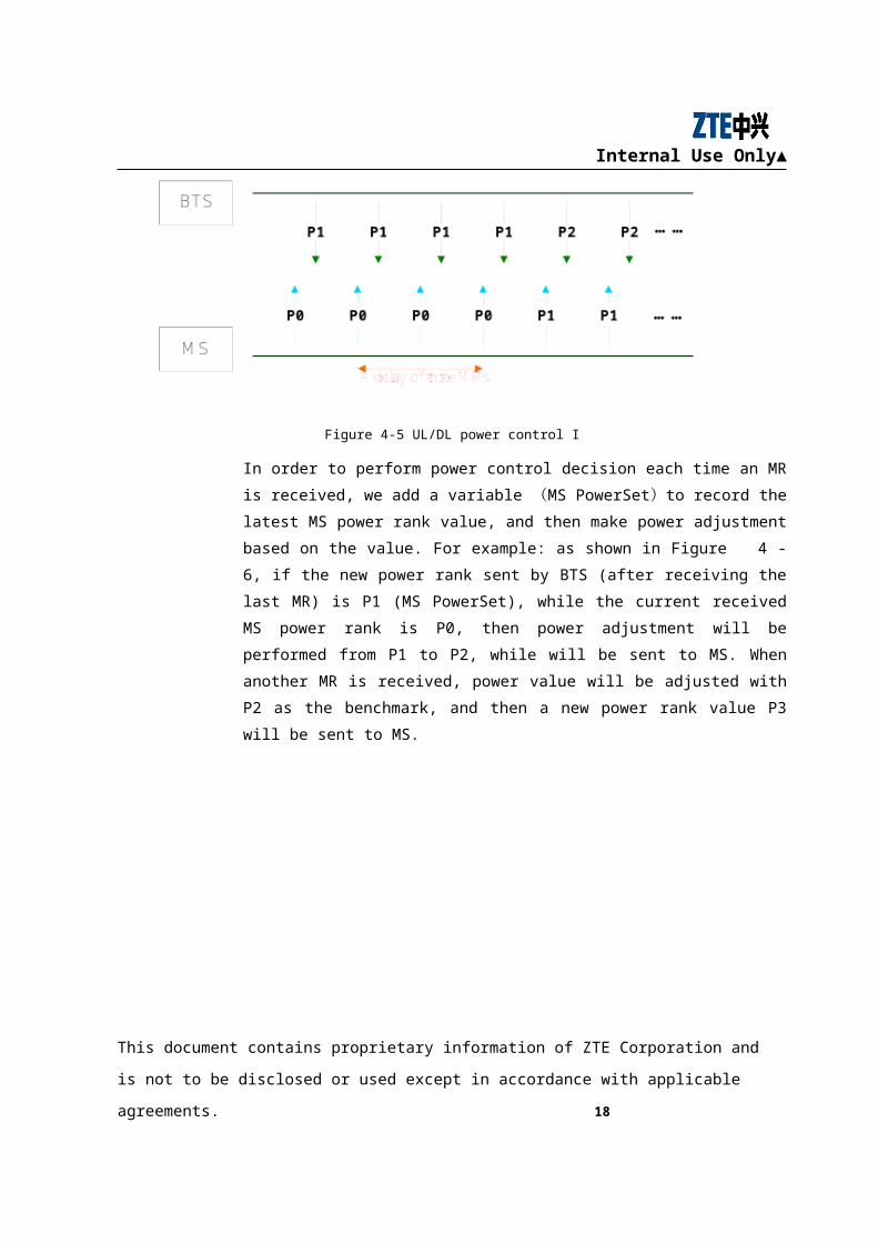
According to MS uplink receive signal level and quality contained in the MRs reported
by CHP, BTS judges the uplink signal state and sends the new power rank to MS after
power control decision. Due to coding problems and air interface delay, MS will not
immediately report the next MR with the new power rank, but report the MR with the
new power rank after a delay of three MRs. As shown in Figure 4-5, if BTS makes
power control decision only after it receives the new power rank that it sends to MS,
the power control is of poor efficiency and timeliness.
Figure 4-5 UL/DL power control I
In order to perform power control decision each time an MR is received, we add a
variable (MS PowerSet) to record the latest MS power rank value, and then make
power adjustment based on the value. For example: as shown in Figure 4-6, if the new
power rank sent by BTS (after receiving the last MR) is P1 (MS PowerSet), while the
current received MS power rank is P0, then power adjustment will be performed from
P1 to P2, while will be sent to MS. When another MR is received, power value will be
This document contains proprietary information of ZTE Corporation and is not to be disclosed or used
except in accordance with applicable agreements. 15
Internal Use Only▲
adjusted with P2 as the benchmark, and then a new power rank value P3 will be sent to
MS.
Figure 4-6 UL/DL power control II
Each adjustment of MS power is based on the latest power rank value, but not the
actual power value that MS uses to report. Because of the complexity and instability of
radio environment, the power rank sent by BTS may be lost if downlink signal is bad.
When there is great difference between the new power rank and the actual one, we take
the new one as benchmark in power adjustment, or power control adjustment will be
invalid. With the aim to ensure the validity of new power rank, we impose specific
decision conditions before new MS power rank is sent.
Power adjustment of BTS is usually effective and in time, and air interface delay and
loss of power rank won’t happen, therefore each time an MR is received correctly,
adjustment of power control decision can be performed.
4.4.3 UL level and quality decision, step size
In the initial state of power control, before making power control of each UL MR
reported by MS, we need to judge the situation of UL signal level and quality.
This document contains proprietary information of ZTE Corporation and is not to be disclosed or used
except in accordance with applicable agreements. 16
Internal Use Only▲
【 1 】 Compare each signal level in the UL MR with the threshold
( byL_RXLEV_UL ) which causes increase of UL power and the threshold
(byU_RELEV_UL) which causes decrease of UL power:
byRxLevel < byL_RXLEV_UL;
byUpLevCause = 1;
or:
byRxLevl > byU_RELEV_UL;
byUpLevCause = 2;
if the level value is within the threshold range, byUpLevCause = 0;
【 2 】 Compare each signal quality in the UL MR with the threshold
( byL_RXQUAL_UL ) which causes increase of UL power and the threshold
(byU_REQUAL_UL) which causes decrease of UL power:
byRxQuality > byL_RXQUAL_UL;
byUpQuaCause = 2;
or:
byRxQuality < byU_RXQUAL_UL;
byUpQuaCause = 1;
if the quality value is within the threshold range, byUpQuaCause = 0。
MS power control decision is performed based on the conditions of signal level and
quality abyMSPowDecision[byUpLevCause][byUpQuaCause]. In order to realize
effective and stable power control in the initial state, regardless power control mode
(INCREASE/DECREASE), the adjustment step size should be set:
STEP = DECREASESTEP。
Adjustment method for step size of BTS power control is the same with that of MS
power control.
This document contains proprietary information of ZTE Corporation and is not to be disclosed or used
except in accordance with applicable agreements. 17
Internal Use Only▲
4.4.4 Power rank control
In the adjustment procedure of MS/BTS transmitting power rank
(changeMS/BSpower), the same power rank control strategy is used in both the initial
state and stable state.
In adjustment of MS power, a variable (byMSpowerSet) is added to save the power
control adjustment value which is sent by BTS. Power control adjustment should be
based on the last power control adjustment value (byMSpowerSet), but not the
currently received MS power rank (byMSpower).
During adjustment, no matter to increase or decrease power, a comparison with the
max and minimum power values allowed in the serving cell. For power increase, power
adjustment value=
MIN2(awGSMPowerCtrlLevel[byMSpowerSet]+byStep, byMS_TXPWR_MAX);
byStep is power adjustment step size;
byMS_TXPWR_MAX:max MS transmitting power (dbm) allowed in the serving
cell.
For power decrease, power adjustment value=
MAX2(awGSMPowerCtrlLevel[byTempMSpowerSet]-
byStep, byMS_TXPWR_MIN);
byMS_TXPWR_MIN:min MS transmitting power (dbm) allowed in the serving cell.
After power adjustment value is confirmed, we need to judge its practicability. When
uplink signal is bad, BTS can not receive the power rank reported by MS. In this case,
a variable (bReceiveMSpower) is added to display whether BTS has received the
power rank reported. If MS power rank is successfully received, set the variable to 1,
and clear it to 0 after each power control.
MS power adjustment takes the latest power rank value (MS PowerSet)sent by BTS
as benchmark. The new MS power rank sent by BTS can be reported by MS only after
an interval of three MRs, so there is a difference (sub) between the new power rank to
be sent and the MS power rank(MS Power) in the currently reported MR. In order
to prevent Sub becoming too large, a limit value of 8db is added in the adjustment of
power decrease; if Sub value exceeds 8db, power adjustment won’t be performed.
This document contains proprietary information of ZTE Corporation and is not to be disclosed or used
except in accordance with applicable agreements. 18
Internal Use Only▲
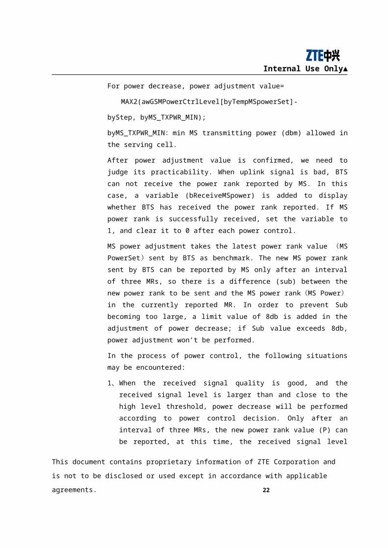
In the process of power control, the following situations may be encountered:
1、When the received signal quality is good, and the received signal level is larger
than and close to the high level threshold, power decrease will be performed
according to power control decision. Only after an interval of three MRs, the new
power rank value (P) can be reported, at this time, the received signal level may be
lower than the low level threshold. In this case, power needs to be improved,
which leads to Pingpong power control (increase-decrease).
Figure 4-7 Power control process
2、UL received signal level is within the threshold range and close to the low level
threshold, while the received signal quality is very good and lower than the low
level threshold. In this case, power control decision is: power decrease due to
quality. After the power control, UL received signal level will be lower than the
low level threshold. In this case, power control decision is: power increase due to
level. In these cases, Pingpong power control (increase-decrease) can also be
caused.
In order to avoid this kind of Pingpong power control, a Margin value is added when
power control decision is to decrease power, which means to make compensation to the
actual power value and judge whether it will be lower than the threshold after power
This document contains proprietary information of ZTE Corporation and is not to be disclosed or used
except in accordance with applicable agreements. 19

Internal Use Only▲
control decision is made. The algorithm is: current received signal level value minus
the power difference value (sub), if the result is lower than the low level threshold,
power control will not be performed; if not, continue the power control adjustment.
if (byRxLevel < byL_RXLEV_UL + bySub)
byL_RXLEV_UL: low threshold of RXLEV, which cause increase of UL power.
If the condition is satisfied, power control will not be performed.
For example: suppose current received level (byRxLevel) =-79dbm,
byL_RXLEV_UL=-88dbm, bySub=8dbm; if power adjustment is made under this
situation, the result will be lower than the threshold. Therefore, Margin value is added
to prevent the unfavorable result.
When power adjustment value is finally confirmed, a new power control rank will be
sent to MS.
In BTS power measurement, the current power rank value of BTS transmitting signal is
used as the benchmark value of power adjustment. The calculation method is the same
as that in the stable state of power control.
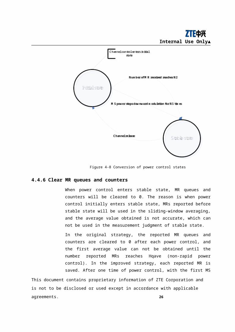
4.4.5 Conversion of power control states
No matter it is MS or BTS power control, they need to enter the stable state from the
initial state. In order to judge the conversion, we set two values (Num1—the number of
“no power decrease”, Num2—total number of MRs) and a counter
( dwPCToStableCount) to MS and BTS. In most cases, the power is adjusted
downward when MS or BTS initially access into channels (SDCCH or TCH). When
the required UL level and quality are achieved, the downward adjustment will be
ended. After each power control decision (byPowDecision), if it’s not needed to
decrease MS or BTS power value, the counter ( dwPCToStableCount) will be
increased by 1. If Num1 is achieved, it is decided that power control enters the stable
state. In order to ensure that all power controls will enter stable state from initial state,
we decide that if the number of reported MRs reaches Num2, power control directly
enters stable state, and Num1<Num2. Meanwhile, change power control state
indication byPCStateInd = INIT_PC_STATE to byPCStateInd = INIT_PC_STATE.
Hereafter, when the next MR is received, UL power control will be performed
according to the power control strategy of stable state.
This document contains proprietary information of ZTE Corporation and is not to be disclosed or used
except in accordance with applicable agreements. 20
Internal Use Only▲
Figure 4-8 Conversion of power control states
4.4.6 Clear MR queues and counters
When power control enters stable state, MR queues and counters will be cleared to 0.
The reason is when power control initially enters stable state, MRs reported before
stable state will be used in the sliding-window averaging, and the average value
obtained is not accurate, which can not be used in the measurement judgment of stable
state.
In the original strategy, the reported MR queues and counters are cleared to 0 after each
power control, and the first average value can not be obtained until the number
reported MRs reaches Hqave (non-rapid power control). In the improved strategy, each
reported MR is saved. After one time of power control, with the first MS MR reported
to BTS and the Hqave-1 MRs saved before, a weighted average can be performed
immediately, and the first average value needed in the power control will be obtained;
after the second MR is received, with the Hqave-1 MRs saved before this one,
weighted average will be continued and the second average value will be obtained.
When byPCDLIncrLevN MRs are received, byPCDLIncrLevN average values will be
This document contains proprietary information of ZTE Corporation and is not to be disclosed or used
except in accordance with applicable agreements. 21
Internal Use Only▲
obtained, with which the first power control decision can be performed. In this way,
power control decision period is greatly shortened. As shown in the following figure,
after power control enters stable state, the time for the first power control decision is
the time used for reporting W+N-1 MRs; from the second power control decision,
power control interval is the time used for reporting N MRs.
Figure 4-9 Window mechanism of power control
4.5 PS power control theories
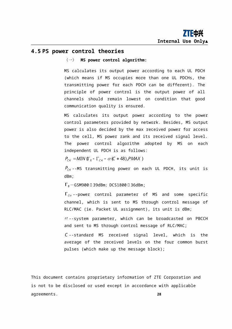
(一) MS power control algorithm:
MS calculates its output power according to each UL PDCH (which means if MS
occupies more than one UL PDCHs, the transmitting power for each PDCH can be
different). The principle of power control is the output power of all channels should
remain lowest on condition that good communication quality is ensured.
MS calculates its output power according to the power control parameters provided by
network. Besides, MS output power is also decided by the max received power for
access to the cell, MS power rank and its received signal level. The power control
algorithm adopted by MS on each independent UL PDCH is as follows:
This document contains proprietary information of ZTE Corporation and is not to be disclosed or used
except in accordance with applicable agreements. 22
Internal Use Only▲
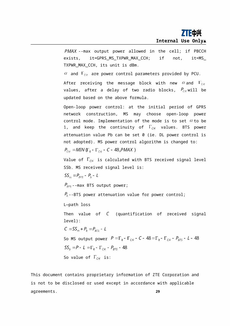
--MS transmitting power on each UL PDCH, its unit is dBm;
-GSM900为 39dBm;DCS1800为 36dBm;
--power control parameter of MS and some specific channel, which is sent to MS
through control message of RLC/MAC (ie. Packet UL assignment), its unit is dBm;
--system parameter, which can be broadcasted on PBCCH and sent to MS through
control message of RLC/MAC;
--standard MS received signal level, which is the average of the received levels on
the four common burst pulses (which make up the message block);
--max output power allowed in the cell; if PBCCH exists,
it=GPRS_MS_TXPWR_MAX_CCH; if not, it=MS_ TXPWR_MAX_CCH, its unit is
dBm.
and are power control parameters provided by PCU.
After receiving the message block with new and values, after a delay of two
radio blocks, will be updated based on the above formula.
Open-loop power control: at the initial period of GPRS network construction, MS may
choose open-loop power control mode. Implementation of the mode is to set to be 1,
and keep the continuity of values. BTS power attenuation value Pb can be set 0
(ie. DL power control is not adopted). MS power control algorithm is changed to:
Value of is calculated with BTS received signal level SSb. MS received signal
level is:
--max BTS output power;
--BTS power attenuation value for power control;
L—path loss
Then value of (quantification of received signal level):
This document contains proprietary information of ZTE Corporation and is not to be disclosed or used
except in accordance with applicable agreements. 23
Internal Use Only▲
So MS output power
So value of is:
MS uses the same output power for the four burst pulses contained in one radio block.
After entering a new cell, MS uses the output power defined by PMAX before it
receives the first new power control parameter.
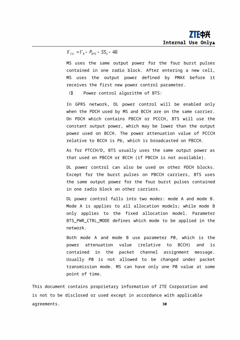
(二) Power control algorithm of BTS:
In GPRS network, DL power control will be enabled only when the PDCH used by MS
and BCCH are on the same carrier. On PDCH which contains PBCCH or PCCCH,
BTS will use the constant output power, which may be lower than the output power
used on BCCH. The power attenuation value of PCCCH relative to BCCH is Pb, which
is broadcasted on PBCCH.
As for PTCCH/D, BTS usually uses the same output power as that used on PBCCH or
BCCH (if PBCCH is not available).
DL power control can also be used on other PDCH blocks. Except for the burst pulses
on PBCCH carriers, BTS uses the same output power for the four burst pulses
contained in one radio block on other carriers.
DL power control falls into two modes: mode A and mode B. Mode A is applies to all
allocation models; while mode B only applies to the fixed allocation model. Parameter
BTS_PWR_CTRL_MODE defines which mode to be applied in the network.
Both mode A and mode B use parameter P0, which is the power attenuation value
(relative to BCCH) and is contained in the packet channel assignment message.
Usually P0 is not allowed to be changed under packet transmission mode. MS can have
only one P0 value at some point of time.
On each PDTCH/D, the PR of MAC head indicates the power decrease rank of current
RLC data block. Coding of PR domain depends on the value of parameter
BTS_PWR_CTRL_MODE. Because of different power control modes, coding of PR
domain is different. Besides, value of PR is calculated based on P0 of the target MS.
This document contains proprietary information of ZTE Corporation and is not to be disclosed or used
except in accordance with applicable agreements. 24
Internal Use Only▲
If power control mode A is adopted, BTS will restrict the block power sent to MS and
keep MS level within (BCCH level-P0-10)dB~(BCCH level-P0)dB.
Output power for other blocks shall not exceed (BCCH level-P0)dB.
If power control mode B is adopted, the overall output power range of BTS will be
involved. In this case, BTS will take (BCCH level-P0)dB as its initial downlink
output power, and all the blocks it sends to a multi-slot MS shall use the same power
within one TDMA frame.
This document contains proprietary information of ZTE Corporation and is not to be disclosed or used
except in accordance with applicable agreements. 25
Internal Use Only▲
5 CS Power Control Parameters & Reference Values
Power control parameters are set with cells as controlled object; each cell is configured
with a series of adjustable power control parameters.
5.1 Uplink /downlink power control
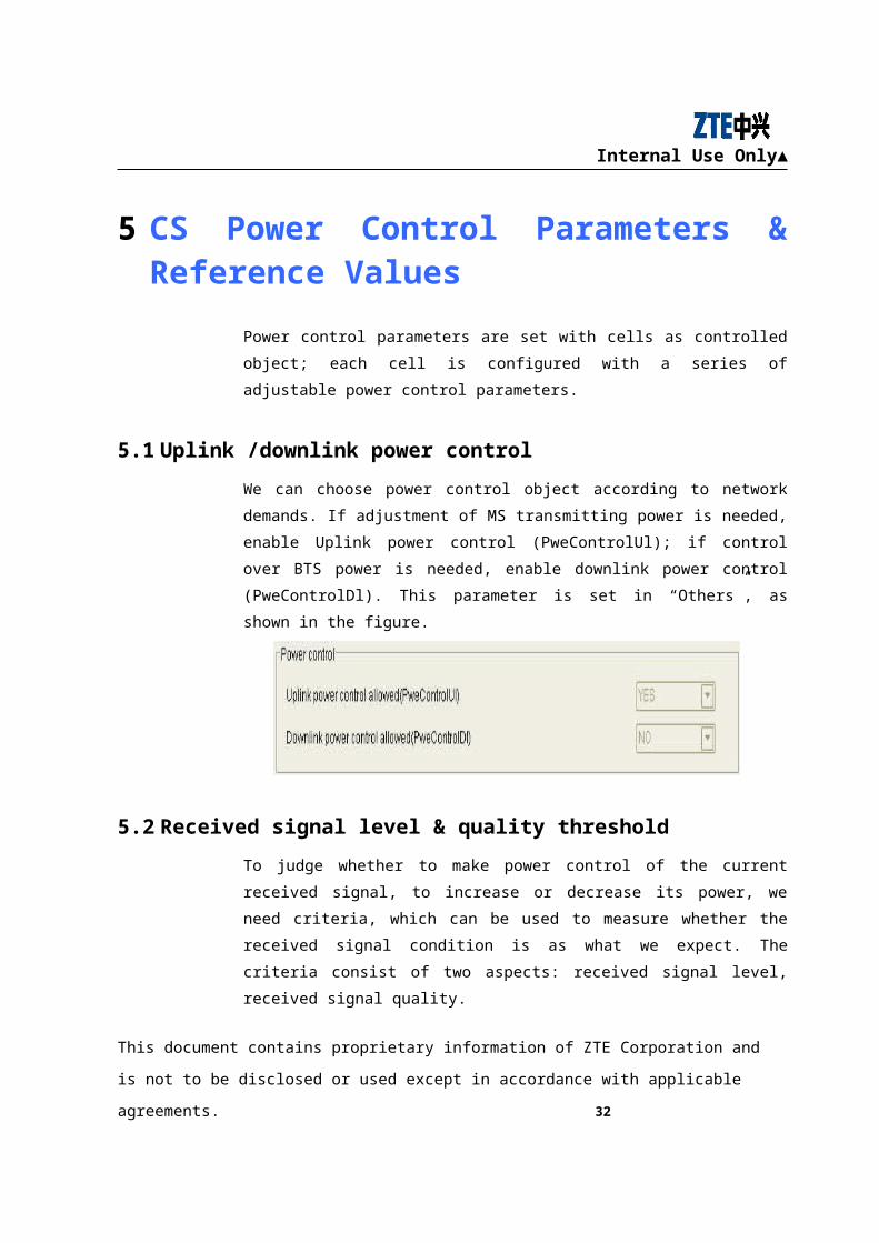
We can choose power control object according to network demands. If adjustment of
MS transmitting power is needed, enable Uplink power control (PweControlUl); if
control over BTS power is needed, enable downlink power control (PweControlDl).
This parameter is set in “Others”, as shown in the figure.
5.2 Received signal level & quality threshold
To judge whether to make power control of the current received signal, to increase or
decrease its power, we need criteria, which can be used to measure whether the
received signal condition is as what we expect. The criteria consist of two aspects:
received signal level, received signal quality.
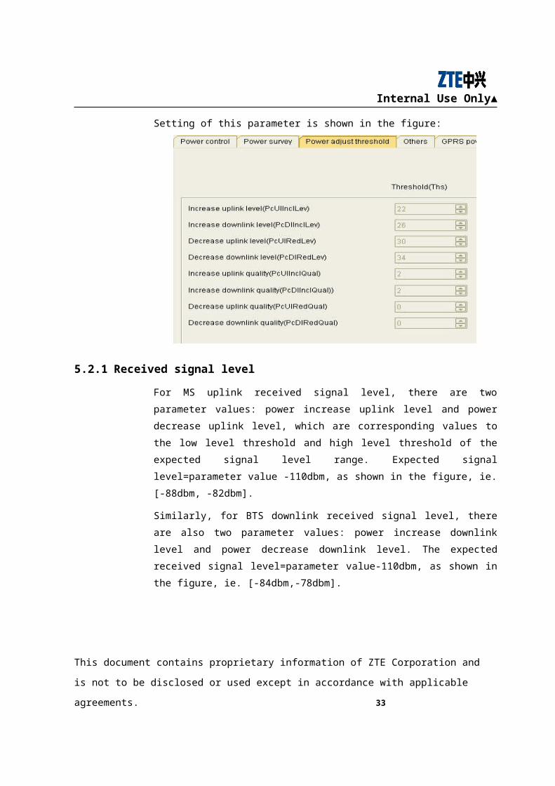
Setting of this parameter is shown in the figure:
This document contains proprietary information of ZTE Corporation and is not to be disclosed or used
except in accordance with applicable agreements. 26
Internal Use Only▲
5.2.1 Received signal level
For MS uplink received signal level, there are two parameter values: power increase
uplink level and power decrease uplink level, which are corresponding values to the
low level threshold and high level threshold of the expected signal level range.
Expected signal level=parameter value -110dbm, as shown in the figure, ie. [-88dbm, -
82dbm].
Similarly, for BTS downlink received signal level, there are also two parameter values:
power increase downlink level and power decrease downlink level. The expected
received signal level=parameter value-110dbm, as shown in the figure, ie. [-84dbm,-
78dbm].
5.2.2 Received signal quality
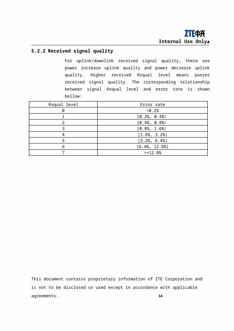
For uplink/downlink received signal quality, there are power increase uplink quality
and power decrease uplink quality. Higher received Rxqual level means poorer
received signal quality. The corresponding relationship between signal Rxqual level
and error rate is shown bellow:
Rxqual level Error rate0 <0.2%
1 [0.2%, 0.4%)2 [0.4%, 0.8%)
This document contains proprietary information of ZTE Corporation and is not to be disclosed or used
except in accordance with applicable agreements. 27

Internal Use Only▲
3 [0.8%, 1.6%)4 [1.6%, 3.2%)
5 [3.2%, 6.4%)
6 [6.4%, 12.8%)
7 >=12.8%
This document contains proprietary information of ZTE Corporation and is not to be disclosed or used
except in accordance with applicable agreements. 28
Internal Use Only▲
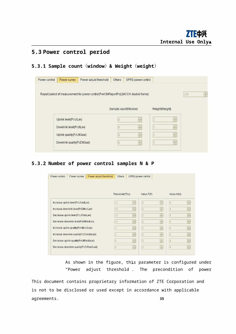
5.3 Power control period
5.3.1 Sample count(window)& Weight(weight)
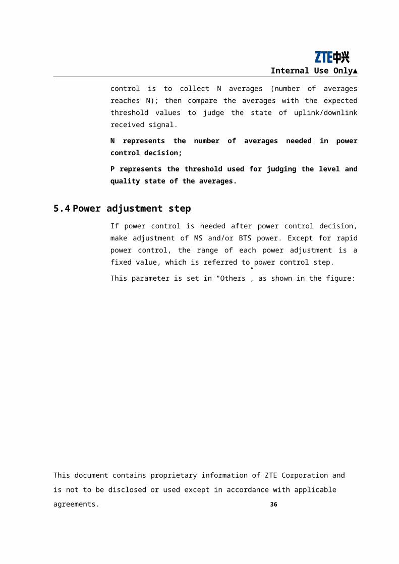
5.3.2 Number of power control samples N & P
As shown in the figure, this parameter is configured under “Power adjust threshold”.
The precondition of power control is to collect N averages (number of averages reaches
N); then compare the averages with the expected threshold values to judge the state of
uplink/downlink received signal.
This document contains proprietary information of ZTE Corporation and is not to be disclosed or used
except in accordance with applicable agreements. 29
Internal Use Only▲
N represents the number of averages needed in power control decision;
P represents the threshold used for judging the level and quality state of the
averages.
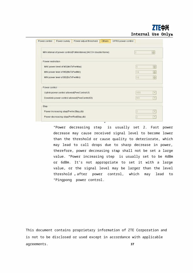
5.4 Power adjustment step
If power control is needed after power control decision, make adjustment of MS and/or
BTS power. Except for rapid power control, the range of each power adjustment is a
fixed value, which is referred to power control step.
This parameter is set in “Others”, as shown in the figure:
“Power decreasing step” is usually set 2. Fast power decrease may cause received
signal level to become lower than the threshold or cause quality to deteriorate, which
may lead to call drops due to sharp decrease in power, therefore, power decreasing step
shall not be set a large value. “Power increasing step” is usually set to be 4dBm or
6dBm. It’s not appropriate to set it with a large value, or the signal level may be larger
than the level threshold after power control, which may lead to “Pingpong” power
control.
This document contains proprietary information of ZTE Corporation and is not to be disclosed or used
except in accordance with applicable agreements. 30
Internal Use Only▲
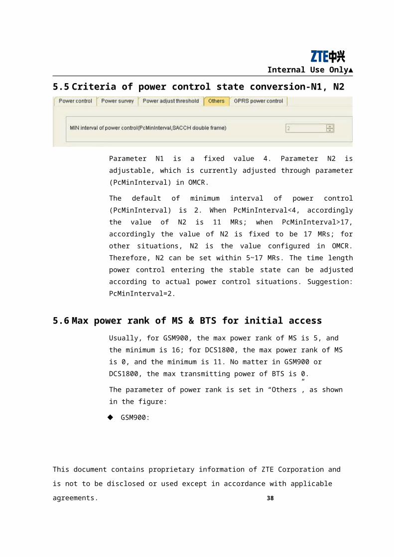
5.5 Criteria of power control state conversion-N1, N2
Parameter N1 is a fixed value 4. Parameter N2 is adjustable, which is currently
adjusted through parameter (PcMinInterval) in OMCR.
The default of minimum interval of power control (PcMinInterval) is 2. When
PcMinInterval<4, accordingly the value of N2 is 11 MRs; when PcMinInterval>17,
accordingly the value of N2 is fixed to be 17 MRs; for other situations, N2 is the value
configured in OMCR. Therefore, N2 can be set within 5~17 MRs. The time length
power control entering the stable state can be adjusted according to actual power
control situations. Suggestion: PcMinInterval=2.
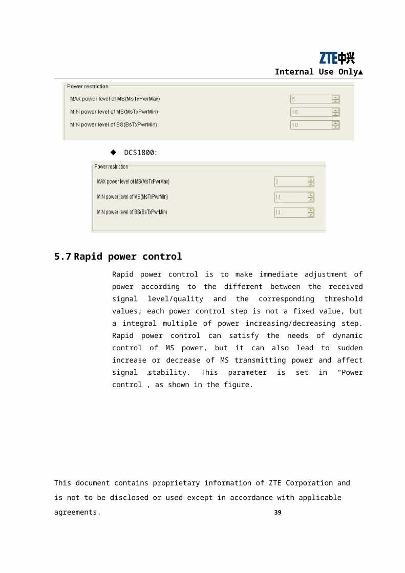
5.6 Max power rank of MS & BTS for initial access
Usually, for GSM900, the max power rank of MS is 5, and the minimum is 16; for
DCS1800, the max power rank of MS is 0, and the minimum is 11. No matter in
GSM900 or DCS1800, the max transmitting power of BTS is 0.
The parameter of power rank is set in “Others”, as shown in the figure:
GSM900:
DCS1800:
This document contains proprietary information of ZTE Corporation and is not to be disclosed or used
except in accordance with applicable agreements. 31
Internal Use Only▲
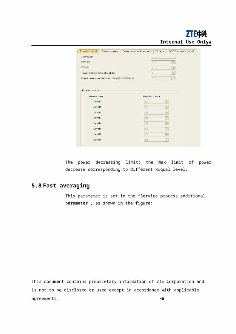
5.7 Rapid power control
Rapid power control is to make immediate adjustment of power according to the
different between the received signal level/quality and the corresponding threshold
values; each power control step is not a fixed value, but a integral multiple of power
increasing/decreasing step. Rapid power control can satisfy the needs of dynamic
control of MS power, but it can also lead to sudden increase or decrease of MS
transmitting power and affect signal stability. This parameter is set in “Power control”,
as shown in the figure.
The power decreasing limit: the max limit of power decrease corresponding to different
Rxqual level.
This document contains proprietary information of ZTE Corporation and is not to be disclosed or used
except in accordance with applicable agreements. 32
Internal Use Only▲
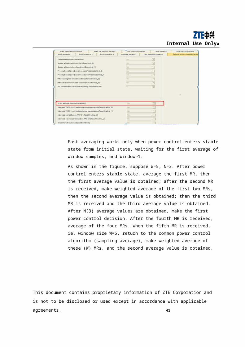
5.8 Fast averaging
This parameter is set in the “Service process additional parameter”, as shown in the
figure:
Fast averaging works only when power control enters stable state from initial state,
waiting for the first average of window samples, and Window>1.
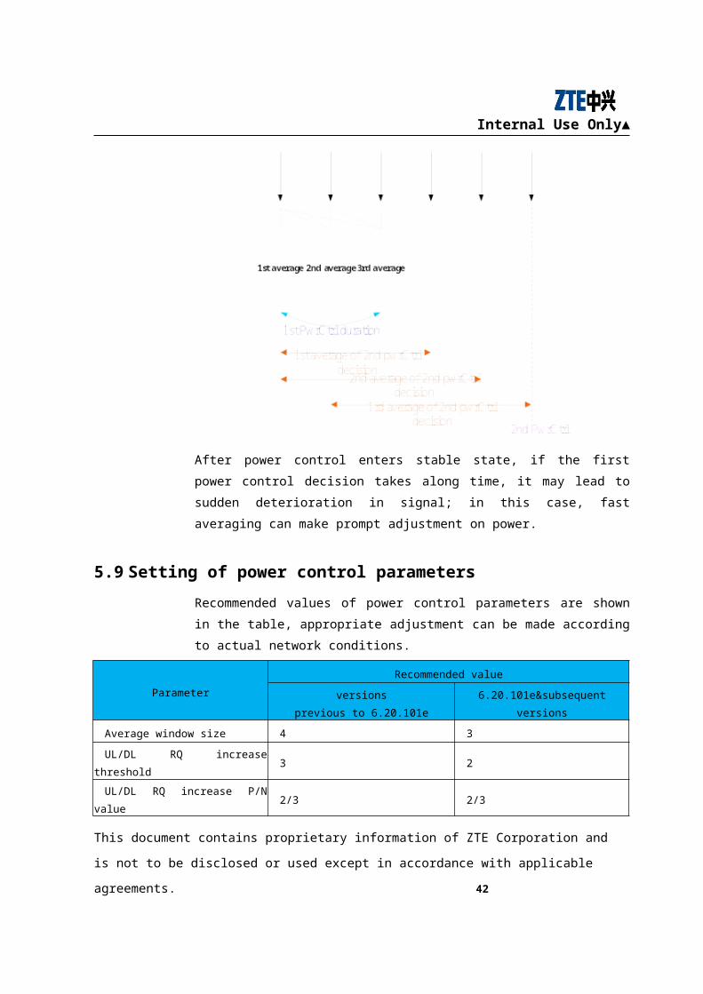
As shown in the figure, suppose W=5, N=3. After power control enters stable state,
average the first MR, then the first average value is obtained; after the second MR is
received, make weighted average of the first two MRs, then the second average value is
obtained; then the third MR is received and the third average value is obtained. After
N(3) average values are obtained, make the first power control decision. After the
fourth MR is received, average of the four MRs. When the fifth MR is received, ie.
window size W=5, return to the common power control algorithm (sampling average),
make weighted average of these (W) MRs, and the second average value is obtained.
This document contains proprietary information of ZTE Corporation and is not to be disclosed or used
except in accordance with applicable agreements. 33
Internal Use Only▲
After power control enters stable state, if the first power control decision takes along
time, it may lead to sudden deterioration in signal; in this case, fast averaging can make
prompt adjustment on power.
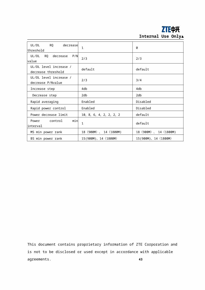
5.9 Setting of power control parameters
Recommended values of power control parameters are shown in the table, appropriate
adjustment can be made according to actual network conditions.
Parameter
Recommended value
versions
previous to 6.20.101e6.20.101e&subsequent versions
Average window size 4 3
UL/DL RQ increase threshold 3 2
UL/DL RQ increase P/N value 2/3 2/3
UL/DL RQ decrease threshold 1 0
UL/DL RQ decrease P/N value 2/3 2/3
UL/DL level increase /
decrease thresholddefault default
UL/DL level increase /
decrease P/Nvalue2/3 3/4
This document contains proprietary information of ZTE Corporation and is not to be disclosed or used
except in accordance with applicable agreements. 34
Internal Use Only▲
Increase step 4db 4db
Decrease step 2db 2db
Rapid averaging Enabled Disabled
Rapid power control Enabled Disabled
Power decrease limit 10,8,6,4,2,2,2,2 default
Power control min interval 1 default
MS min power rank 18(900M)、14(1800M) 18(900M)、14(1800M)
BS min power rank 15(900M)、14(1800M) 15(900M)、14(1800M)
This document contains proprietary information of ZTE Corporation and is not to be disclosed or used
except in accordance with applicable agreements. 35
Internal Use Only▲
6 Setting of Power Control Parameters in Different Scenarios
6.1 Setting of signal quality threshold (under poor DL radio environment)
During operation of power control, what affects network performance seriously is the
distribution of uplink and downlink RQ (=0~7). Due to the complexity of network,
uplink /downlink received signal quality threshold is usually set 【0, 2】, which can help
increase the proportion of network performance indicator RQ(=0~3).
Signal quality threshold range can be changed according to the actual uplink/downlink
radio environment. If radio environment is not good, we can change the quality
threshold range to 【0, 1】. However, increase in quality threshold may lead to increase
of uplink/downlink signal power, and hence the interference between uplink and
downlink signals will increase, especially the interference in downlink. Because of
power control, the proportion of network performance indicator RQ(=0~3) remains
high. When optimizing related parameters, we need to weigh increase of the proportion
of RQ=0~3 against increase of interference.
6.2 Setting of uplink/downlink power control period
Because the interference of uplink and downlink signals is different, we can adjust
UL/DL power control parameters separately. The new power control strategy features
fast frequency and timely adjustment. If radio environment is good, the downlink
power control frequency can be appropriately slowed down, that is to increase power
control decision time N. When making sliding-window averaging, if too many MRs
reported with the last sent power rank are used, the proportion of MRs reported with
new power rank will be low, thus the averaged level and quality values will be affected,
and the accuracy of new power control decision will be lowered, therefore, the number
of samples (window) should be reduced. The recommended values of related downlink
parameters are:
Sample count(W) Value N Value P
This document contains proprietary information of ZTE Corporation and is not to be disclosed or used
except in accordance with applicable agreements. 36
Internal Use Only▲
2 5 3
6.3 Handover threshold
When adjusting the range of uplink/downlink received signal level and quality
thresholds, we must ensure that there should be no conflicts with thresholds related to
BSC handover algorithms. The level threshold which causes power increase should
NOT be lower than the handover level threshold; the quality threshold which causes
power increase should be lower than the quality handover threshold. If quality
handover threshold =4, N=1, then the high limit of power control threshold should not
exceed 2. If power control can be performed, optimize signal level through power
control; if not, carry out handover. Besides, power control parameters can be adjusted
according to network performance indicators, like handover success rate, call drop rate,
etc..
6.4 Highway/ railway
On highways and railways, MS/BTS power control should be performed in fast
frequency and timely manner, so value N should not be a large value; meanwhile,
number of samples (W) should be reduced to improve accuracy; and we should not use
too many MRs reported with the last sent power rank in the averaging process.
Sample count(W) Value N Value P
1 3 2
6.5 Building
In office buildings and apartment buildings, MS moves in a slow speed, or stays still.
In this case, the basic setting of power control parameters can be adopted, and power
control duration N can also be extended.
This document contains proprietary information of ZTE Corporation and is not to be disclosed or used
except in accordance with applicable agreements. 37
Internal Use Only▲
7 Examples of Power Control
Figure 7-10 Graph of UL ordinary power control
Figure 7-11 Graph of UL ordinary power control with fast averaging
This document contains proprietary information of ZTE Corporation and is not to be disclosed or used
except in accordance with applicable agreements. 38
Internal Use Only▲
Figure 7-12 Graph of UL rapid power control
Figure 7-13 Graph of DL ordinary power control
This document contains proprietary information of ZTE Corporation and is not to be disclosed or used
except in accordance with applicable agreements. 39
Internal Use Only▲
Figure 7-14 Graph of DL ordinary power control with fast averaging adopted
Figure 7-15 Graph of DL rapid power control
This document contains proprietary information of ZTE Corporation and is not to be disclosed or used
except in accordance with applicable agreements. 40
Internal Use Only▲
Figure 7-16 Graph of DL rapid power control with fast averaging adopted
Experiment 1, see Figure 7-10, Graph of UL ordinary power control
Conditions: ordinary power control over uplink, step=2dB; no power control
over downlink; MS stays 5m away from the BS after the call finished.
Result analysis: the graphs shows that MS power is adjusted from 39dBm
(time-16:01:34.577) to 13dBm (time-16:02:38.934), the adjustment time is
64.357s, adjustment period is 4.801s/2dB. Besides, the graph shows that MS
power remains steady after the adjustment.
Experiment 2, see Figure 7-102, Graph of UL ordinary power control with fast
averaging
Conditions: ordinary power control with fast averaging is adopted over
uplink; no power control over downlink; MS stays 5m away from the BS
after the call is finished.
Result analysis: the graph shows that MS power is adjusted from 39dBm
(time-19:49:54.524) to 13dBm (time-19:50:29.525), the adjustment time is
35.001s, adjustment period is 2.399s/2dB. Compared with experiment 1, the
This document contains proprietary information of ZTE Corporation and is not to be disclosed or used
except in accordance with applicable agreements. 41
Internal Use Only▲
adjustment period in the experiment is only half of that in experiment 1;
power control speed is greatly increased.
Experiment 3, see Figure 7-12, Graph of UL rapid power control
Conditions: rapid power control over uplink; no power control over
downlink; MS stays 5m away from the BS after the call is finished.
Result analysis: the graph shows that MS power is adjusted from 39dBm
(time-19:16:20.903) to 13dBm (time-19:16:26.648), the adjustment time is
5.745s. Compared with experiment 1 and 2, the adjustment time is noticeably
shorter than that in the previous experiments.
Experiment 4, see Figure 7-13, Graph of DL ordinary power control
Conditions: ordinary power control over downlink; no power control over
uplink; MS stays 5m away from the site when the call starts; after a while,
MS moves far away from the BS.
Result analysis: the graph shows that BS power is adjusted from 0dB (time-
15:52:52.833) to -30dB (time-15:54:07.261), the adjustment time is 74.428s,
adjustment period is 4.799s/2dB. When MS stays near the BS, BS power is
gradually adjusted to the minimum value; when MS moves far away from the
BS, its received signal level drops and voice quality deteriorates, so BS keeps
increasing its transmitting power.
Experiment 5, see Figure 7-14, Graph of DL ordinary power control with fast
averaging adopted
Conditions: ordinary power control with fast averaging over downlink; no
power control over uplink; MS stays 5m away from the site when the call
starts; after a while, MS moves far away from the BS; finally, MS returns to
BS.
Result analysis: the graph shows that BS power is adjusted from 0dB (time-
16:52:35.329) to -30dB (time-16:53:15.631), the adjustment time is 40.302s,
adjustment period is1.934s/2dB. When MS stays near the BS, BS power is
gradually adjusted to the minimum value; when MS moves far away from the
BS, its received signal level drops and voice quality deteriorates, so BS keeps
increasing its transmitting power; when MS returns to stay near BS, BS
This document contains proprietary information of ZTE Corporation and is not to be disclosed or used
except in accordance with applicable agreements. 42
Internal Use Only▲
adjusts its power back to the original value. Compared with experiment 4,
both the adjustment time and period are shortened to a great extent
experiment 5.
Experiment 6, seeFigure 7-15, Graph of DL rapid power control
Conditions: rapid power control over downlink; no power control over
uplink; MS stays 5m away from the site when the call starts; after a while,
MS moves far away from the BS; finally, MS returns to BS.
Result analysis: the graph shows that BS power is adjusted from 0dB (time-
17:08:00.626) to -30dB (time-17:08:16.964), the adjustment time is 16.338s.
When MS stays near the BS, BS power is gradually adjusted to the minimum
value; when MS moves far away from the BS, its received signal level drops
and voice quality deteriorates, so BS keeps increasing its transmitting power
and makes compensation to the fast attenuation of signal level; when MS
returns to stay near BS, BS adjusts its power back to the original value and
keeps MS received signal level and quality stable. Compared with
experiment 4 and 5, the adjustment time is noticeably shortened in
experiment 6.
Experiment 6, see Figure 7-16, Graph of DL rapid power control with fast
averaging adopted
Conditions: rapid power control with fast averaging over downlink; no power
control over uplink; MS stays 5m away from the site when the call starts;
after a while, MS moves far away from the BS; finally, MS returns to BS.
Result analysis: the graph shows that BS power is adjusted from 0dB (time-
17:19:57.659) to -30dB (time-17:20:07.259), the adjustment time is 9.6s.
When MS stays near the BS, BS power is gradually adjusted to the minimum
value; when MS moves far away from the BS, its received signal level drops
and voice quality deteriorates, so BS keeps increasing its transmitting power
and makes compensation to the fast attenuation of signal level; when MS
returns to stay near BS, BS adjusts its power back to the original value and
keeps MS received signal level and quality stable. Especially at around
17:21:03, when fast attenuation occurs to MS RxLev, and higher error rate
occurs to MS RxQual, BS immediately increases its power to save the call.
This document contains proprietary information of ZTE Corporation and is not to be disclosed or used
except in accordance with applicable agreements. 43
Internal Use Only▲
Compared with the salvage of call at 17:09:30 in experiment 6, the one in
experiment 7 is even faster. Compared with experiment 4, 5 and 6, the
adjustment time is noticeably shortened in experiment 7.
This document contains proprietary information of ZTE Corporation and is not to be disclosed or used
except in accordance with applicable agreements. 44