Embed Size (px)
Citation preview
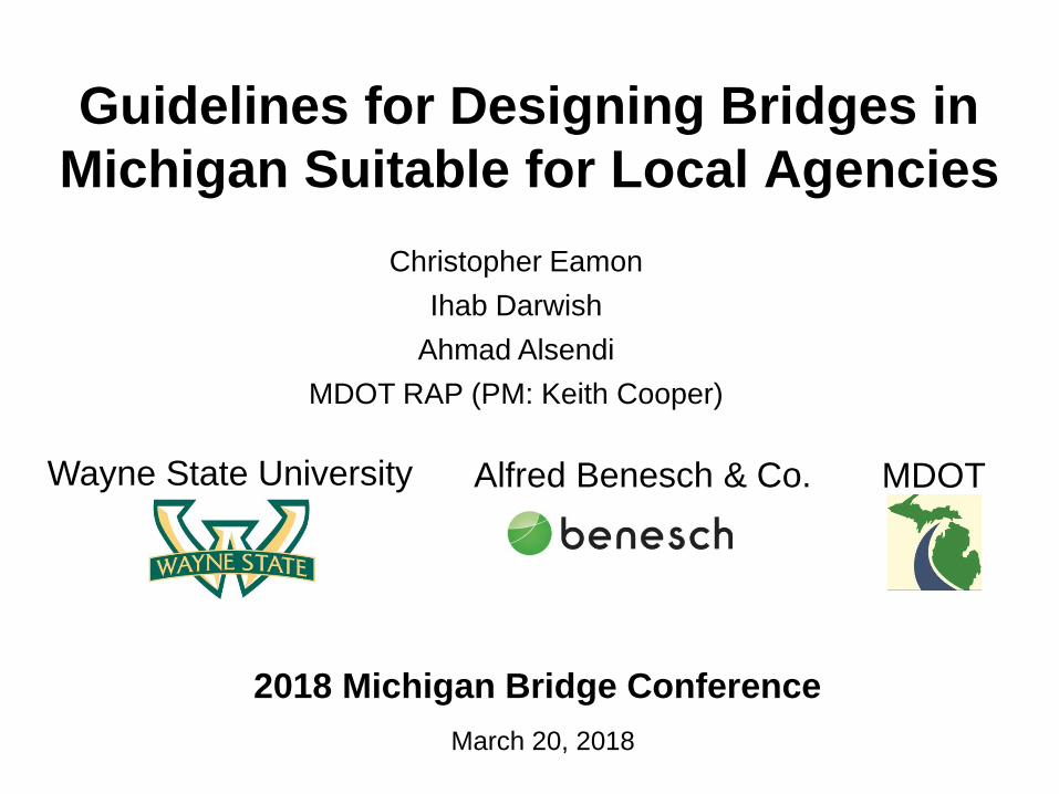
Guidelines for Designing Bridges in
Michigan Suitable for Local Agencies
Wayne State University
2018 Michigan Bridge Conference
March 20, 2018
Alfred Benesch & Co.
Christopher Eamon
Ihab Darwish
Ahmad Alsendi
MDOT RAP (PM: Keith Cooper)
MDOT

Overview
• Background
• Guideline Development
• Example: Steel Bridge Plans
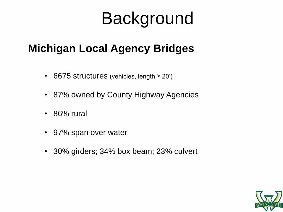
Background
• 6675 structures (vehicles, length ≥ 20’)
• 87% owned by County Highway Agencies
• 86% rural
• 97% span over water
• 30% girders; 34% box beam; 23% culvert
Michigan Local Agency Bridges
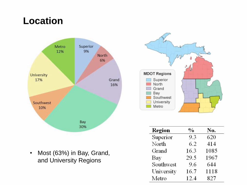
Location
• Most (63%) in Bay, Grand,
and University Regions
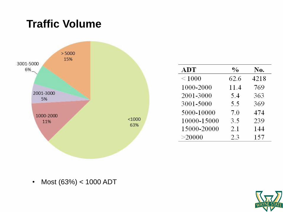
Traffic Volume
• Most (63%) < 1000 ADT
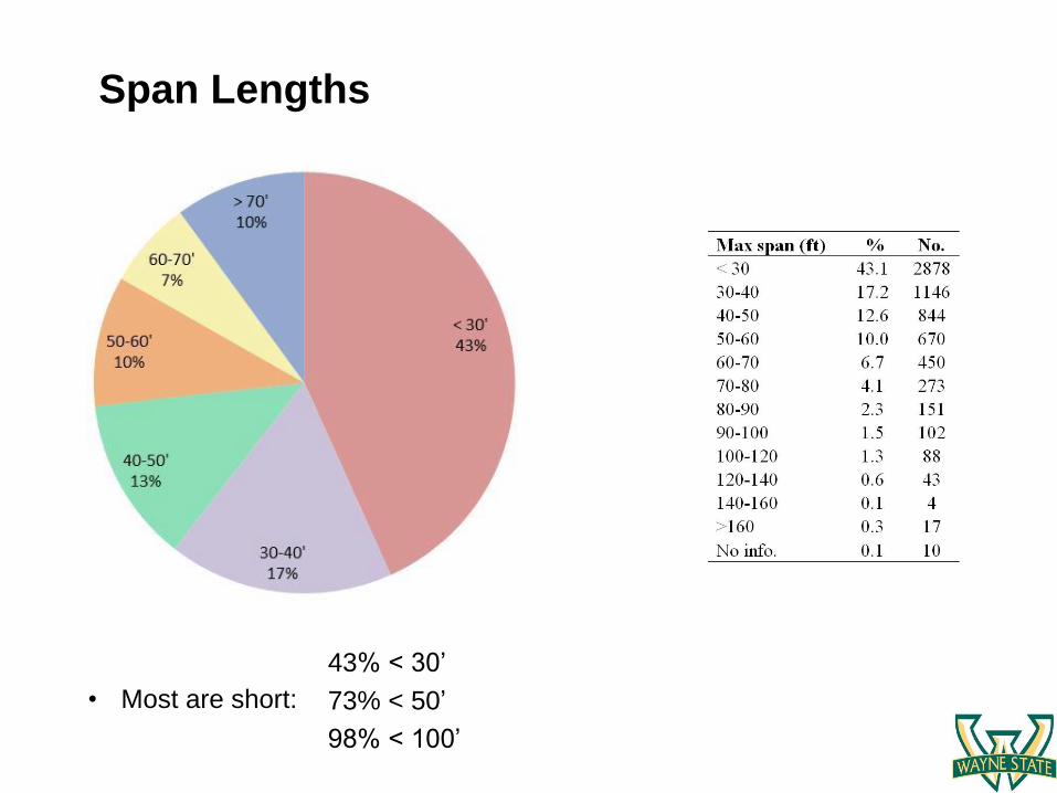
Span Lengths
• Most are short:
43% < 30’
73% < 50’
98% < 100’

Skew
• 91% < 30˚
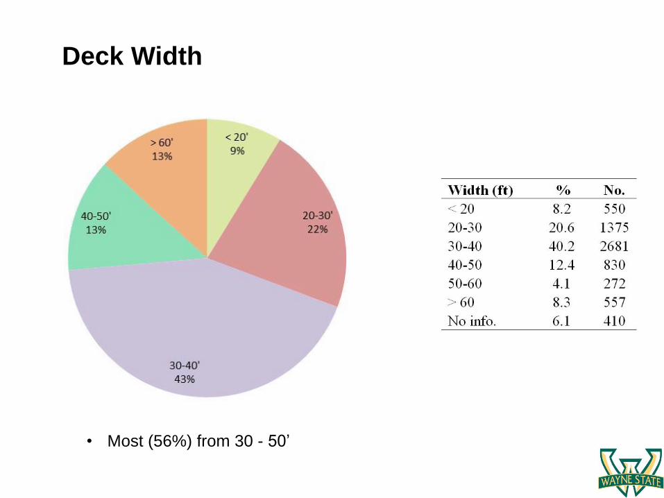
Deck Width
• Most (56%) from 30 - 50’
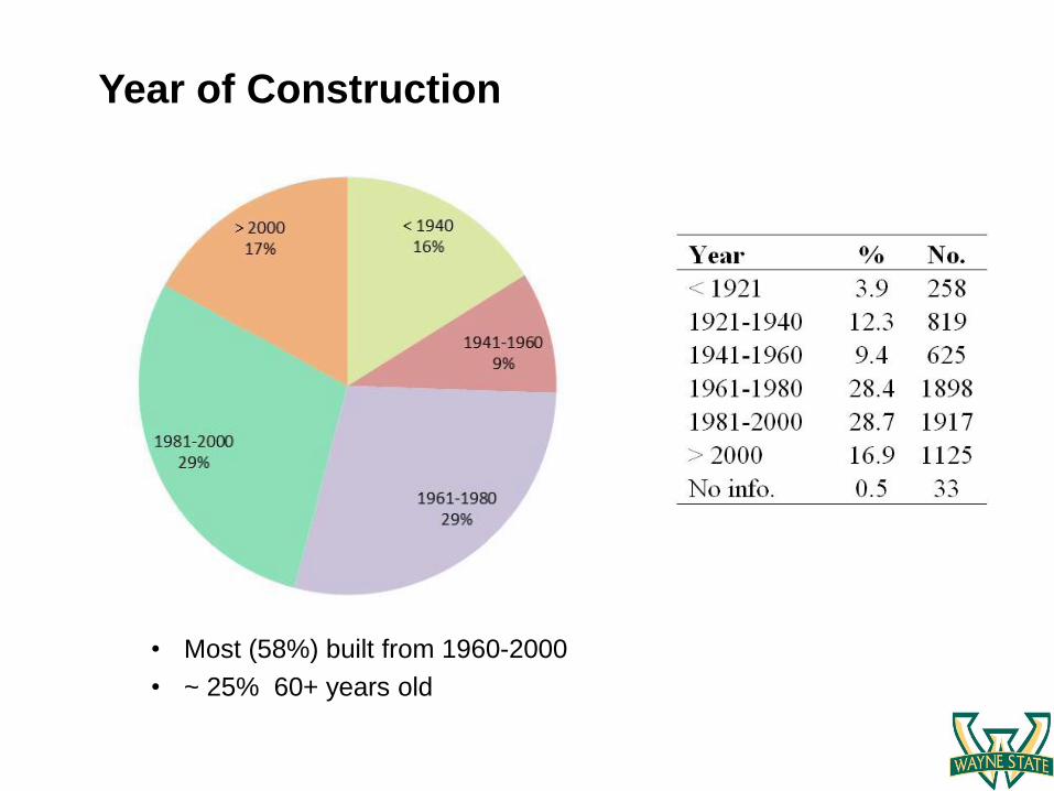
Year of Construction
• Most (58%) built from 1960-2000
• ~ 25% 60+ years old
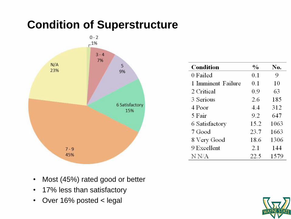
Condition of Superstructure
• Most (45%) rated good or better
• 17% less than satisfactory
• Over 16% posted < legal
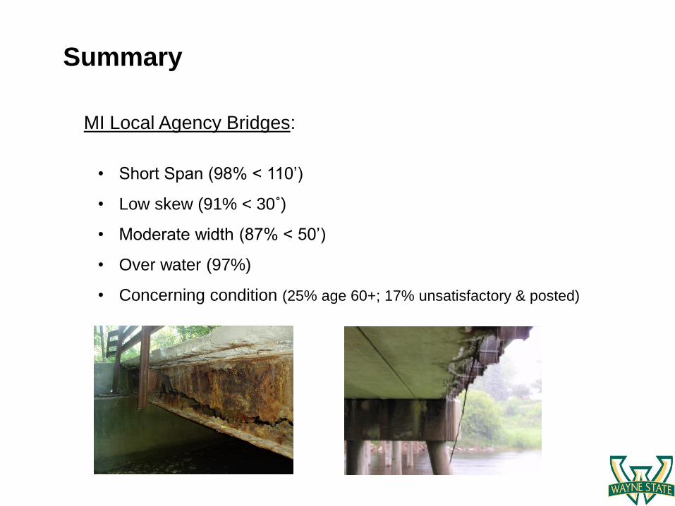
Summary
• Short Span (98% < 110’)
• Low skew (91% < 30˚)
• Moderate width (87% < 50’)
• Over water (97%)
• Concerning condition (25% age 60+; 17% unsatisfactory & posted)
MI Local Agency Bridges:
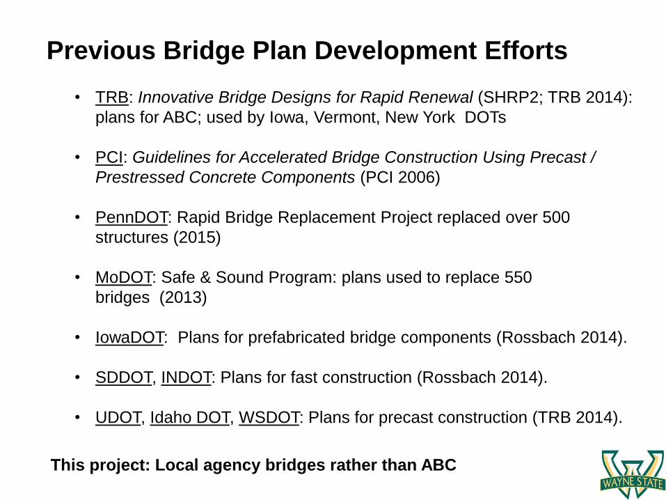
• TRB: Innovative Bridge Designs for Rapid Renewal (SHRP2; TRB 2014):
plans for ABC; used by Iowa, Vermont, New York DOTs
• PCI: Guidelines for Accelerated Bridge Construction Using Precast /
Prestressed Concrete Components (PCI 2006)
• PennDOT: Rapid Bridge Replacement Project replaced over 500
structures (2015)
• MoDOT: Safe & Sound Program: plans used to replace 550
bridges (2013)
• IowaDOT: Plans for prefabricated bridge components (Rossbach 2014).
• SDDOT, INDOT: Plans for fast construction (Rossbach 2014).
• UDOT, Idaho DOT, WSDOT: Plans for precast construction (TRB 2014).
Previous Bridge Plan Development Efforts
This project: Local agency bridges rather than ABC
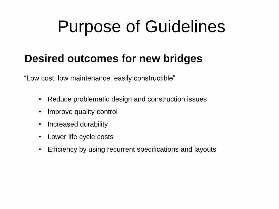
Purpose of Guidelines
Desired outcomes for new bridges
• Reduce problematic design and construction issues
• Improve quality control
• Increased durability
• Lower life cycle costs
• Efficiency by using recurrent specifications and layouts
“Low cost, low maintenance, easily constructible”
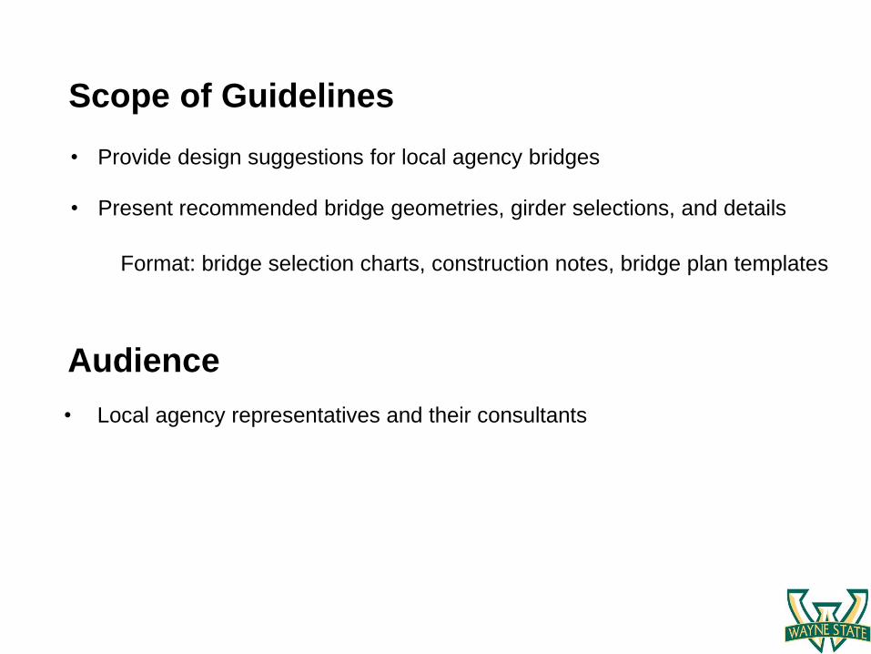
Scope of Guidelines
• Provide design suggestions for local agency bridges
• Present recommended bridge geometries, girder selections, and details
Format: bridge selection charts, construction notes, bridge plan templates
Audience
• Local agency representatives and their consultants
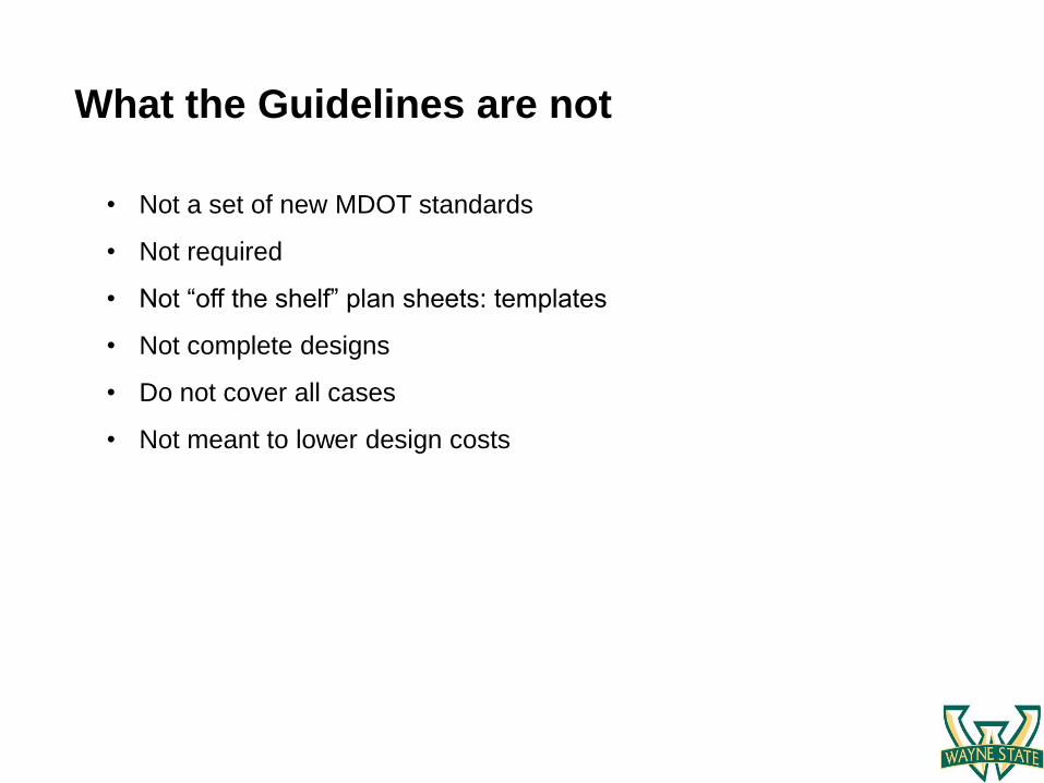
• Not a set of new MDOT standards
• Not required
• Not “off the shelf” plan sheets: templates
• Not complete designs
• Do not cover all cases
• Not meant to lower design costs
What the Guidelines are not
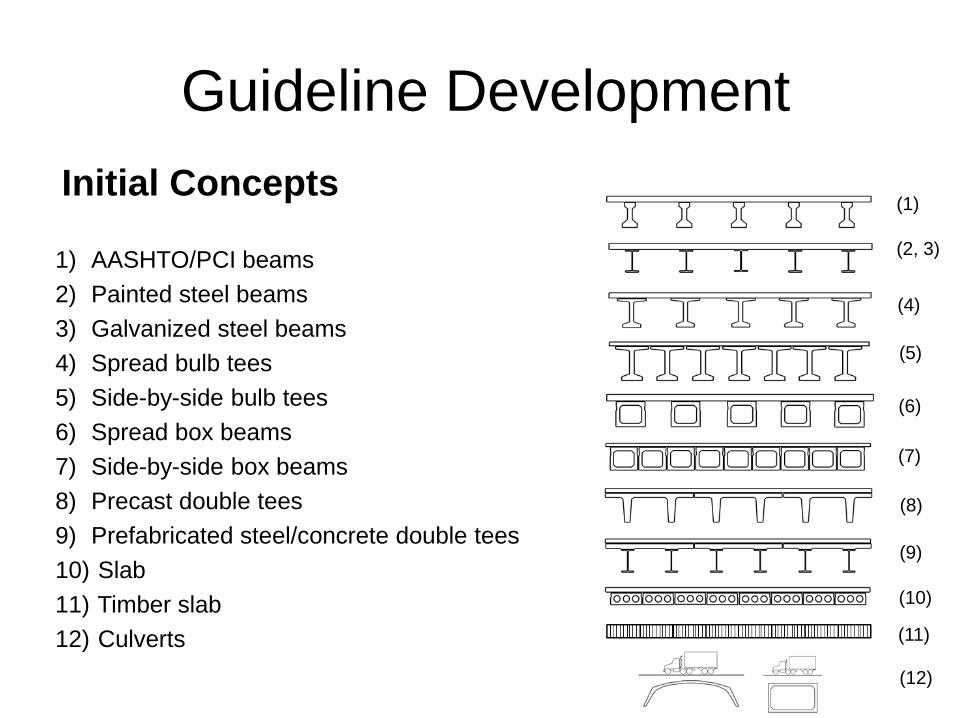
Initial Concepts
Guideline Development
1) AASHTO/PCI beams
2) Painted steel beams
3) Galvanized steel beams
4) Spread bulb tees
5) Side-by-side bulb tees
6) Spread box beams
7) Side-by-side box beams
8) Precast double tees
9) Prefabricated steel/concrete double tees
10) Slab
11) Timber slab
12) Culverts
(1)
(4)
(2, 3)
(5)
(6)
(7)
(8)
(9)
(10)
(11)
(12)
Concept Review
• On-line survey (advertised in Crossroads Magazine)
Local agency representatives, engineering consultants,
contractors, fabricators
About 90 responses
• Focus group meeting (July 2016)
Discussed performance, cost, constructability,
durability/maintenance, other issues
• Questionnaire distributed to 2017 MBC
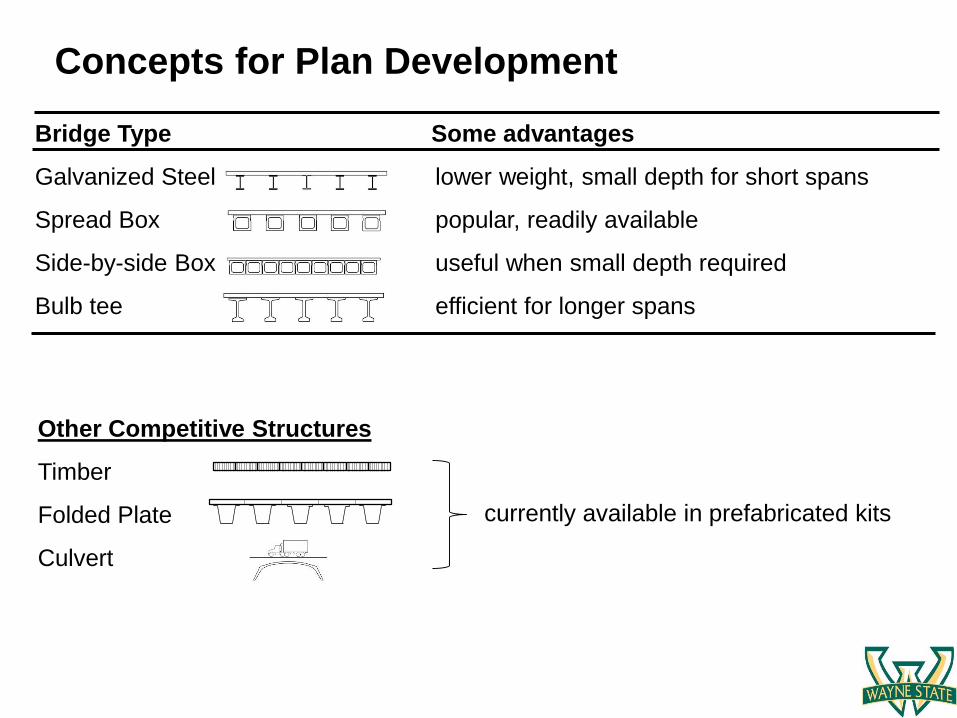
Concepts for Plan Development
Bridge Type Some advantages
Galvanized Steel lower weight, small depth for short spans
Spread Box popular, readily available
Side-by-side Box useful when small depth required
Bulb tee efficient for longer spans
Other Competitive Structures
Timber
Folded Plate
Culvert
currently available in prefabricated kits
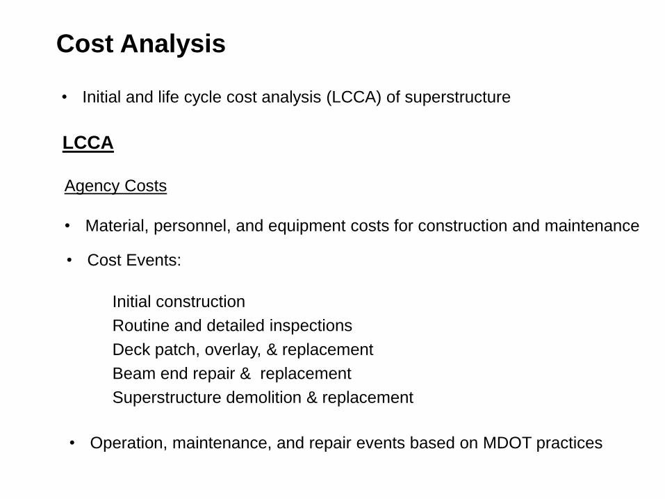
• Initial and life cycle cost analysis (LCCA) of superstructure
LCCA
• Operation, maintenance, and repair events based on MDOT practices
Cost Analysis
Agency Costs
• Material, personnel, and equipment costs for construction and maintenance
• Cost Events:
Initial construction
Routine and detailed inspections
Deck patch, overlay, & replacement
Beam end repair & replacement
Superstructure demolition & replacement
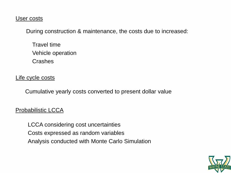
User costs
During construction & maintenance, the costs due to increased:
Life cycle costs
Cumulative yearly costs converted to present dollar value
Probabilistic LCCA
LCCA considering cost uncertainties
Costs expressed as random variables
Analysis conducted with Monte Carlo Simulation
Travel time
Vehicle operation
Crashes
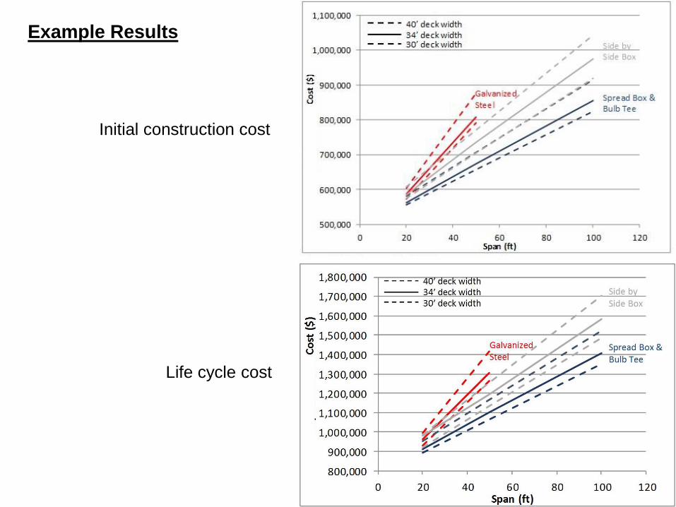
Life cycle cost
Example Results
Initial construction cost
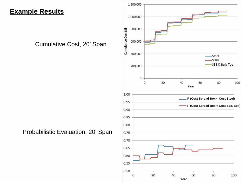
Probabilistic Evaluation, 20’ Span
Cumulative Cost, 20’ Span
Example Results
P (Cost Spread Box < Cost Steel)
P (Cost Spread Box < Cost SBS Box)
Year
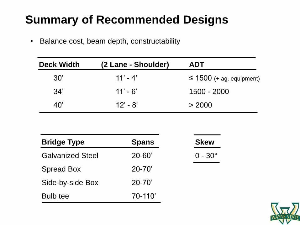
• Balance cost, beam depth, constructability
Summary of Recommended Designs
Deck Width (2 Lane - Shoulder) ADT
30’ 11’ - 4’ ≤ 1500 (+ ag. equipment)
34’ 11’ - 6’ 1500 - 2000
40’ 12’ - 8’ > 2000
Bridge Type Spans
Galvanized Steel 20-60’
Spread Box 20-70’
Side-by-side Box 20-70’
Bulb tee 70-110’
Skew
0 - 30°
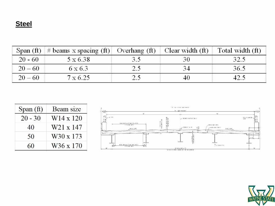
Steel
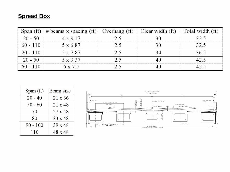
Spread Box
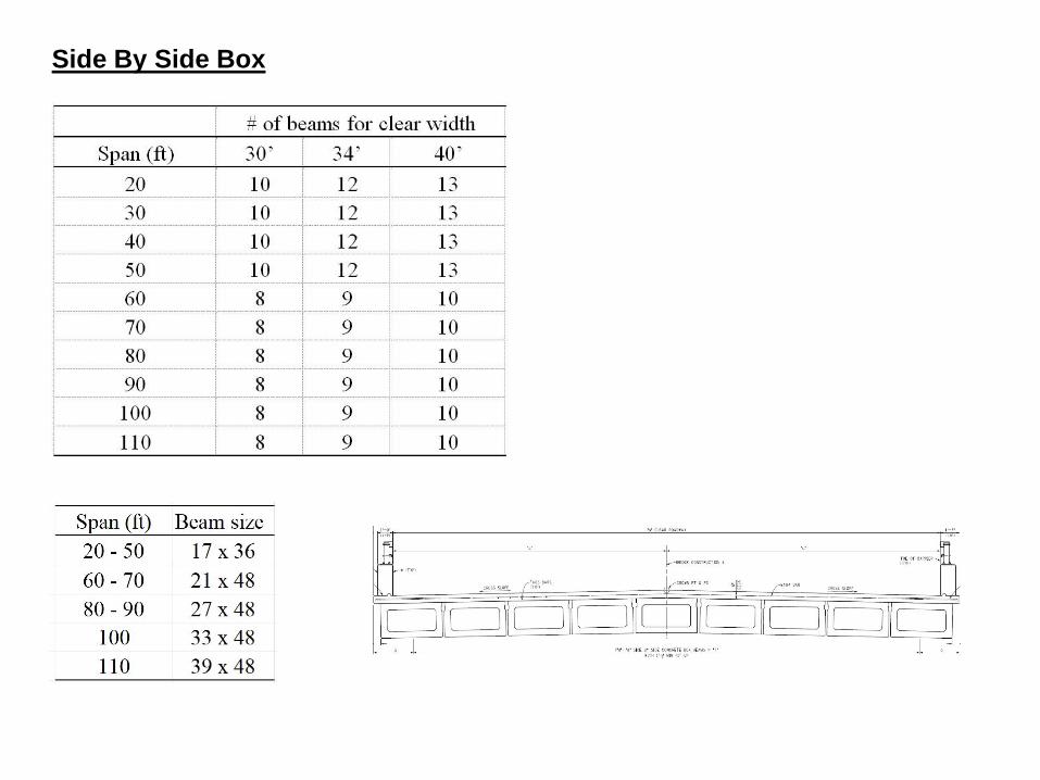
Side By Side Box
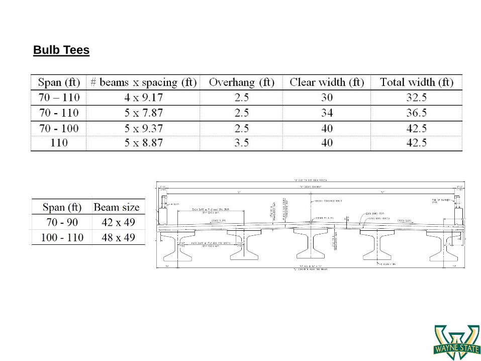
Bulb Tees
Design Guidelines
Summary Document
• Summary of design considerations
• Discussion of bridge types & pros/cons of selections
• Initial span/depth selection charts
• Initial and life cycle cost estimates
• Discussion of design assumptions/limitations on plan templates
• Example design
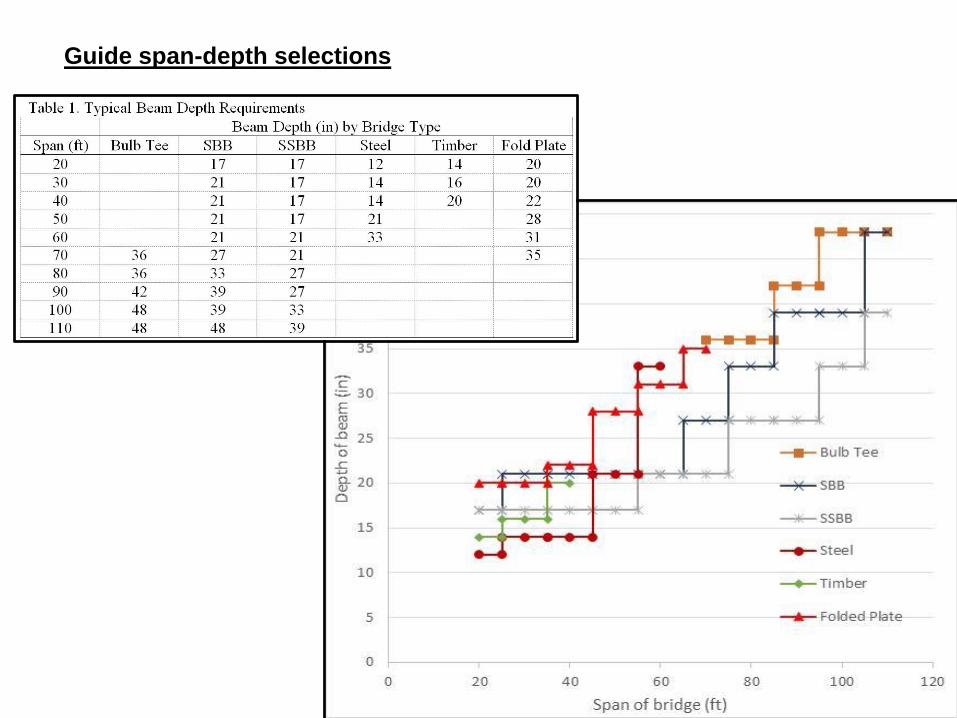
Guide span-depth selections
Summarizes:
• Sheet contents
• Variable-defined items
• Inputs required
• Selections required
• Explanatory notes
Guide template use instructions

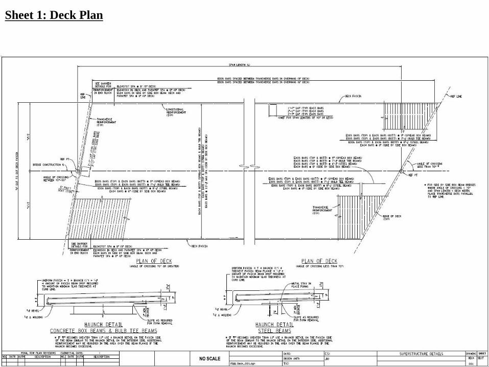
Sheet 1: Deck Plan
Contains: deck plan, haunch detail
Variable items: span length (L), out-to-out bridge width (a), angle of crossing,
deck reinforcement, structural slab thickness (T), fascia depth (F), haunch
detail
Select: haunch detail (for concrete or steel beams), angle of crossing case
Notes: The left side of the deck plan applies to angles of crossing from 70-
90˚, while the right side applies to angles of crossing 60-70˚. Deck plan
should be redrawn to appropriately match the required angle of crossing. See
section sheets for out-to-out width dimension (a).
Example template instruction information
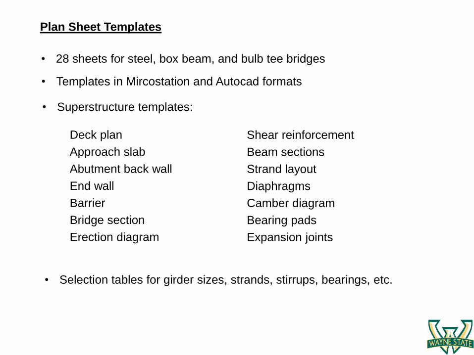
• Templates in Mircostation and Autocad formats
Plan Sheet Templates
• Selection tables for girder sizes, strands, stirrups, bearings, etc.
• Superstructure templates:
• 28 sheets for steel, box beam, and bulb tee bridges
Deck plan
Approach slab
Abutment back wall
End wall
Barrier
Bridge section
Erection diagram
Shear reinforcement
Beam sections
Strand layout
Diaphragms
Camber diagram
Bearing pads
Expansion joints
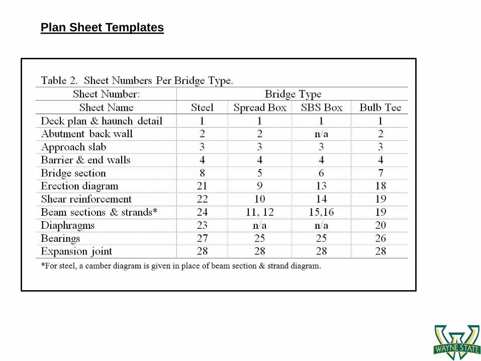
Plan Sheet Templates

Sheets needed:
1: Deck plan
2: Abutment back wall
3: Approach slab
4: Barrier and end wall
8: Bridge section
21: Erection diagram
22: Shear studs
23: Diaphragms
24: Camber diagram
27: Bearing assembly
28: Expansion joints
Example: Steel Bridge Sheets
Sheet 1: Deck Plan
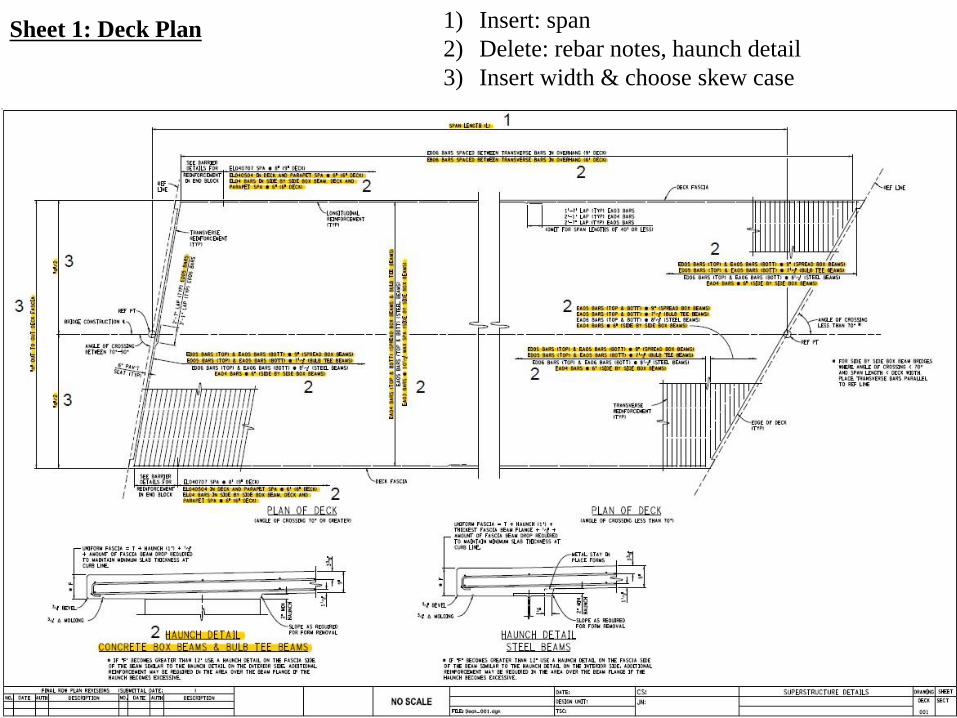
1) Insert: span
2) Delete: rebar notes, haunch detail
3) Insert width & choose skew case
Sheet 1: Deck Plan
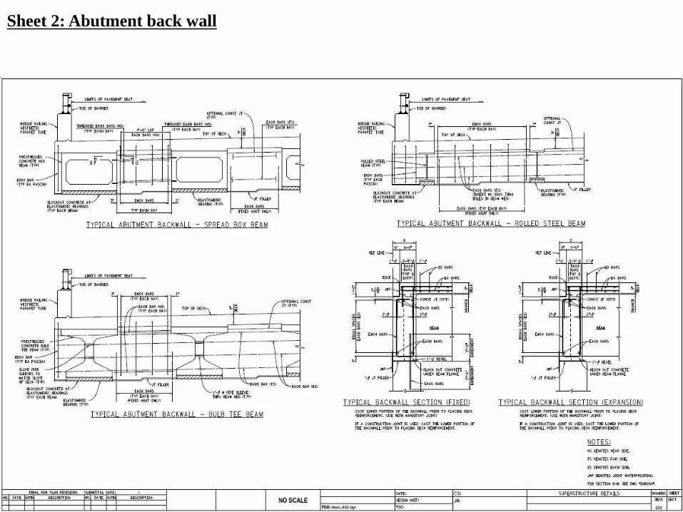
Sheet 2: Abutment back wall
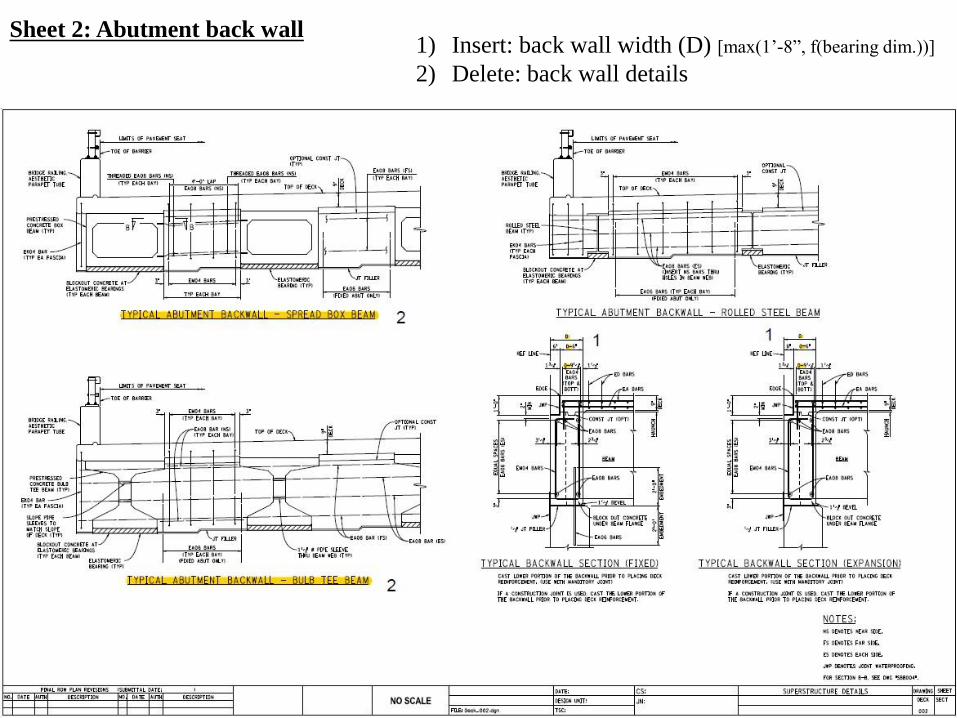
Sheet 2: Abutment back wall1) Insert: back wall width (D) [max(1’-8”, f(bearing dim.))]
2) Delete: back wall details
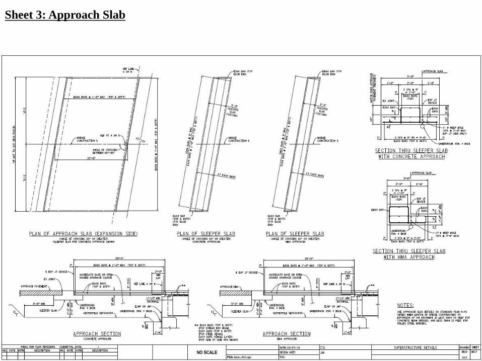
Sheet 3: Approach Slab
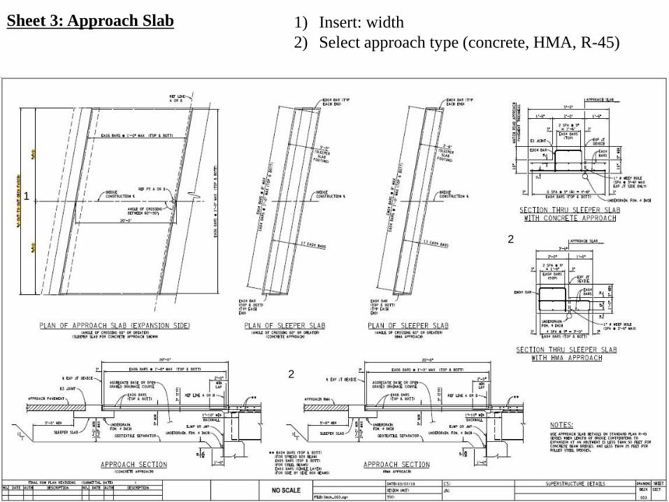
Sheet 3: Approach Slab 1) Insert: width
2) Select approach type (concrete, HMA, R-45)
1
2
2
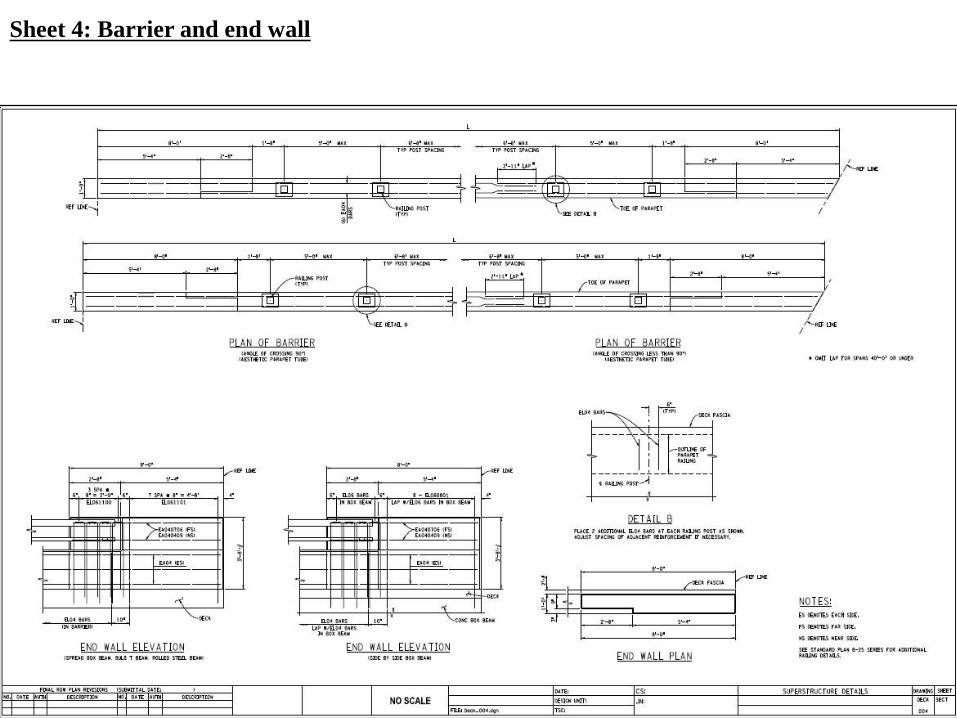
Sheet 4: Barrier and end wall
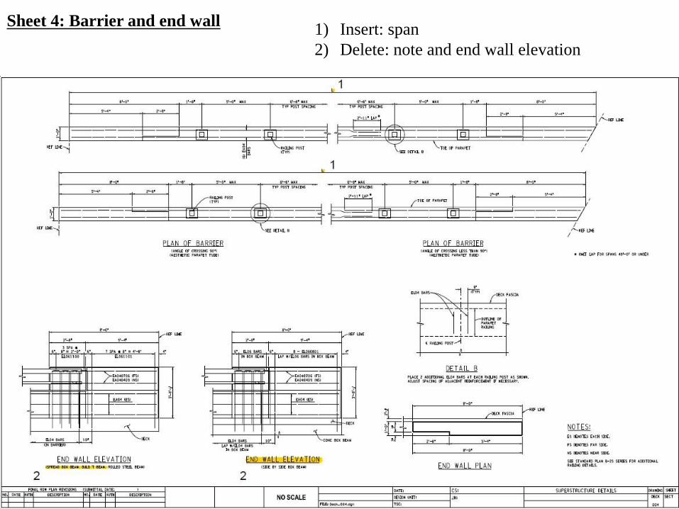
Sheet 4: Barrier and end wall1) Insert: span
2) Delete: note and end wall elevation
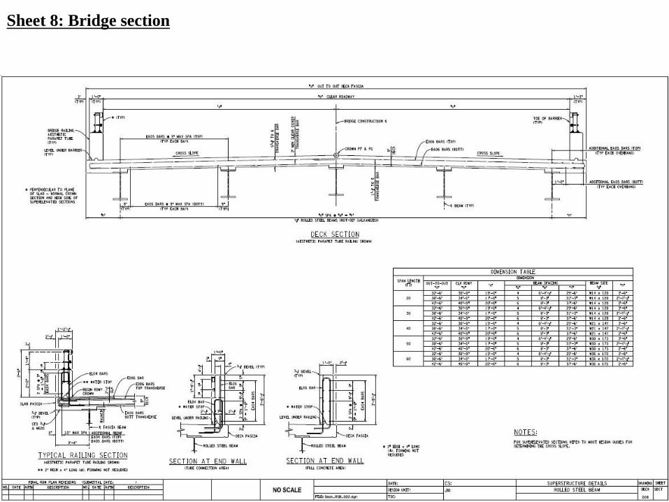
Sheet 8: Bridge section
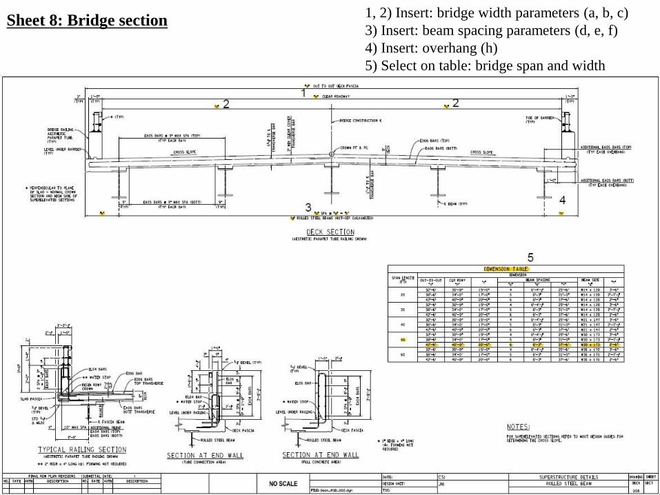
Sheet 8: Bridge section1, 2) Insert: bridge width parameters (a, b, c)
3) Insert: beam spacing parameters (d, e, f)
4) Insert: overhang (h)
5) Select on table: bridge span and width
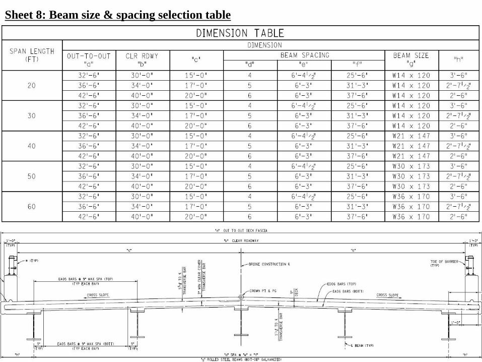
Sheet 8: Beam size & spacing selection table
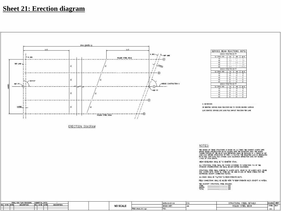
Sheet 21: Erection diagram

Sheet 21: Erection diagram1, 2) Insert: bridge length (L; L/2)
3) Insert: angle of crossing (θ)
4) Read reactions per bridge type
5) Enter material quantities
1
22
3 4
5

Sheet 22: Shear studs
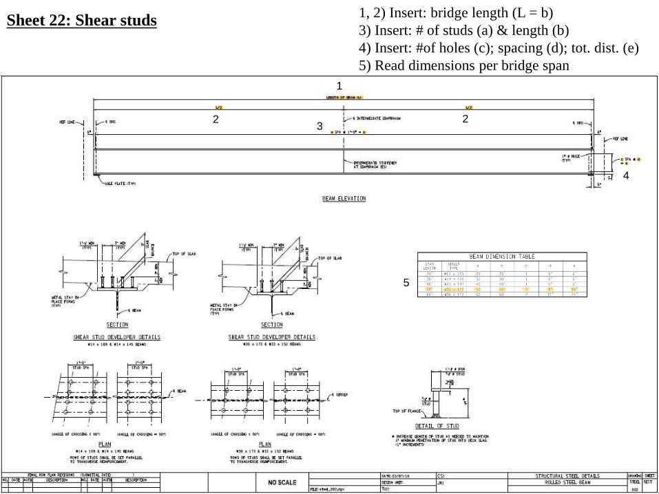
Sheet 22: Shear studs1, 2) Insert: bridge length (L = b)
3) Insert: # of studs (a) & length (b)
4) Insert: #of holes (c); spacing (d); tot. dist. (e)
5) Read dimensions per bridge span
1
2 23
4
5
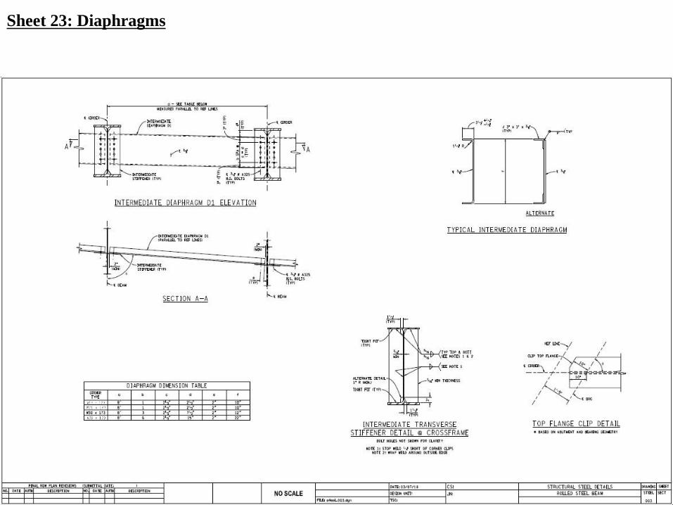
Sheet 23: Diaphragms
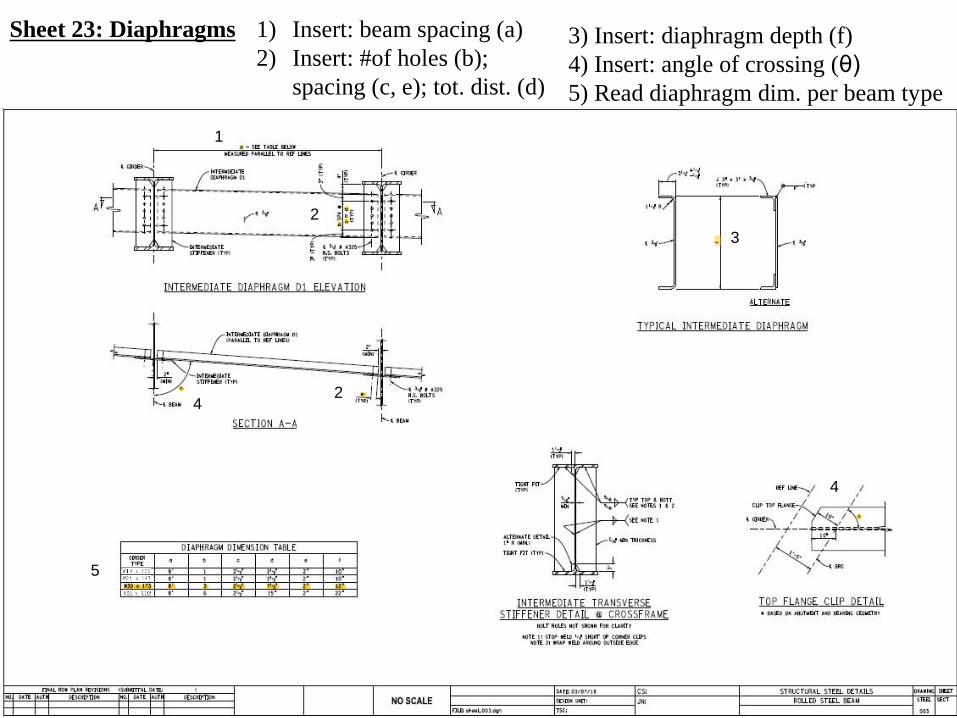
Sheet 23: Diaphragms 1) Insert: beam spacing (a)
2) Insert: #of holes (b);
spacing (c, e); tot. dist. (d)
4
2
5
2
1
3
4
3) Insert: diaphragm depth (f)
4) Insert: angle of crossing (θ)
5) Read diaphragm dim. per beam type

Sheet 24: Camber diagram
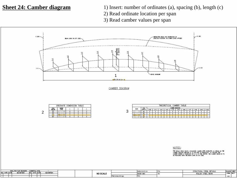
Sheet 24: Camber diagram 1) Insert: number of ordinates (a), spacing (b), length (c)
2) Read ordinate location per span
3) Read camber values per span
1
2 3
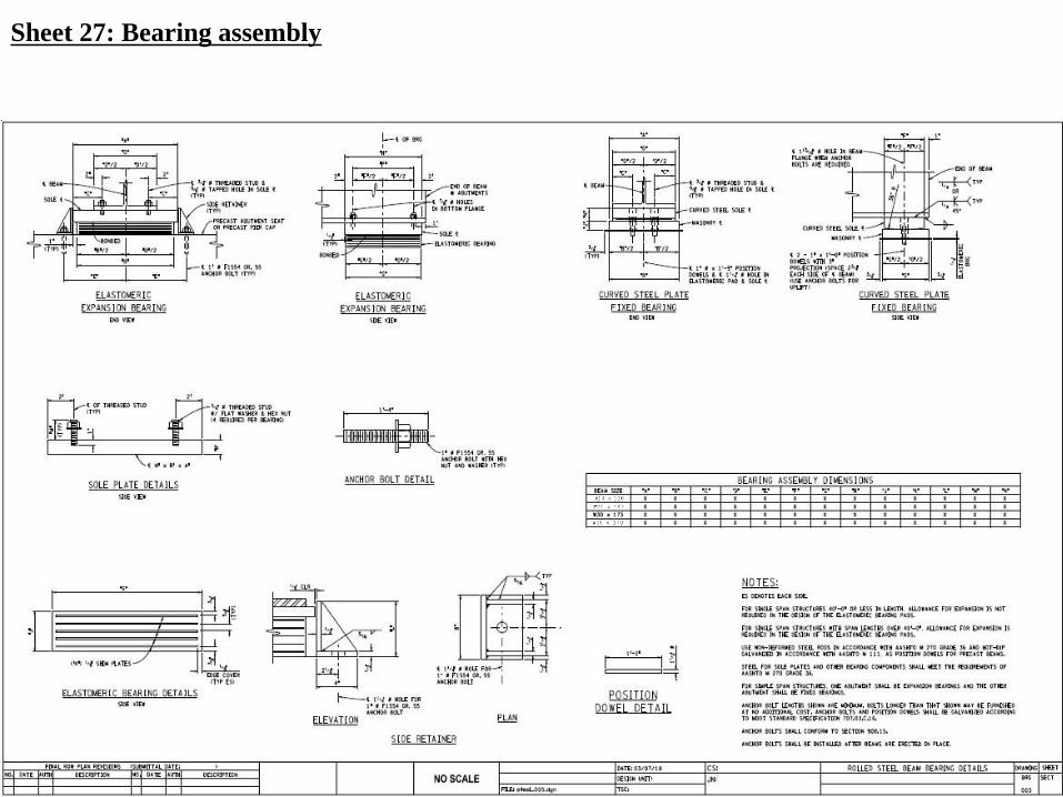
Sheet 27: Bearing assembly
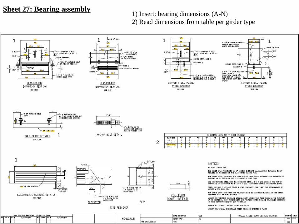
Sheet 27: Bearing assembly1) Insert: bearing dimensions (A-N)
2) Read dimensions from table per girder type
1 1 1 1
1
1
2
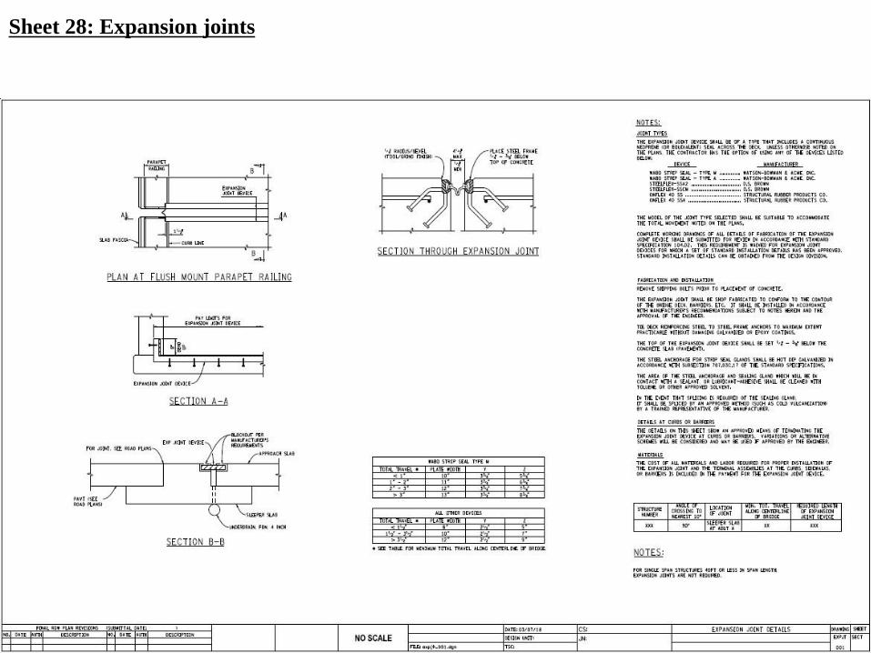
Sheet 28: Expansion joints
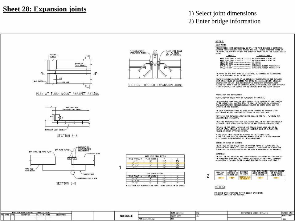
Sheet 28: Expansion joints1) Select joint dimensions
2) Enter bridge information
2
1

Wayne State University Alfred Benesch & Co. MDOT


![Catalog 1-8martie · ARANJAMENTE PLANTE Cod: FL19 Compozi]ie: bulb de zambila, campanula (muscari), muschi. Compozi]ie: bulb de zambila, bulb de lalea, muschi stabilizat. Cod: FL20](https://img.pdfslide.tips/doc/110x75/5f05b35b7e708231d414447c/catalog-1-8martie-aranjamente-plante-cod-fl19-compoziie-bulb-de-zambila-campanula.jpg)