Embed Size (px)
Citation preview
High P
ower S
ystems
Toggle Presses ...... Oil Pack Cylinders
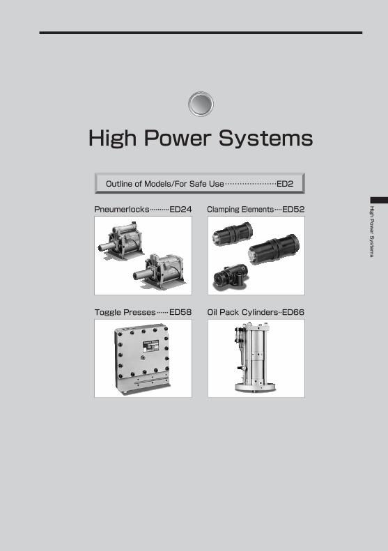
Pneumerlocks..........ED24
ED58
ED52 Clamping Elements....
ED66..
High Power Systems
Outline of Models/For Safe Use…………………ED2
Outline of ModelsHigh Power SystemsHigh Power Systems
2ED
Outline of Models High Power SystemsHigh P
ower S
ystems
3ED
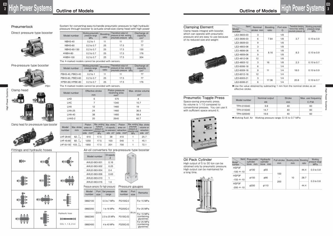
Pneumerlock
Direct pressure type booster
Pre-pressure type booster
System for converting easy-to-handle pneumatic pressure to high hydraulic pressure through booster to actuate small-size clamp head with high power
Model numberWorking pneumatic
pressure rangeMPa
Boostingratio
Theoretical output oil pressure at max. working pneumatic pressure MPa
Discharge oilcapacity
cm3
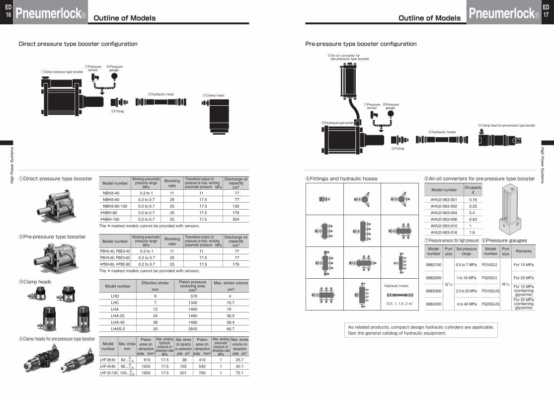
NBH3-40
NBH3-60
NBH3-60-130
*NBH-80
*NBH-100
0.2 to 1
0.2 to 0.7
0.2 to 0.7
0.2 to 0.7
0.2 to 0.7
11
25
25
25
25
11
17.5
17.5
17.5
17.5
77
77
130
176
304
The *-marked models cannot be provided with sensors.
Model numberWorking pneumatic
pressure rangeMPa
Boostingratio
Theoretical output oil pressure at max. working pneumatic pressure MPa
Discharge oilcapacity
cm3
PBH3-40, PBE3-40
PBH3-60, PBE3-60
*PBH-80,*PBE-80
0.2 to 1
0.2 to 0.7
0.2 to 0.7
11
25
25
11
17.5
17.5
77
77
176
The *-marked models cannot be provided with sensors.
Clamp head
Clamp head for pre-pressure type booster
Fittings and hydraulic hoses
Model numberEffective stroke Piston pressure
receiving areamm2mm
Max. stroke volume
cm3
LHD
LHC
LHA
LHA-25
LHA-40
LHAS-2
6
7
12
24
38
20
570
1340
1460
1460
1460
2640
4
10.7
19
36.5
58.4
60.7
Modelnumber
Max. strokemm
Pistonarea on
extensionside mm2
Pistonarea on
retractionside mm2
Max. workinghydraulic
pressure onextension side
MPa
Max. strokeoil capacity
on extensionside cm3
Max. workingpneumatic
pressure onretraction side
MPa
Max. strokevolume onretractionside cm3
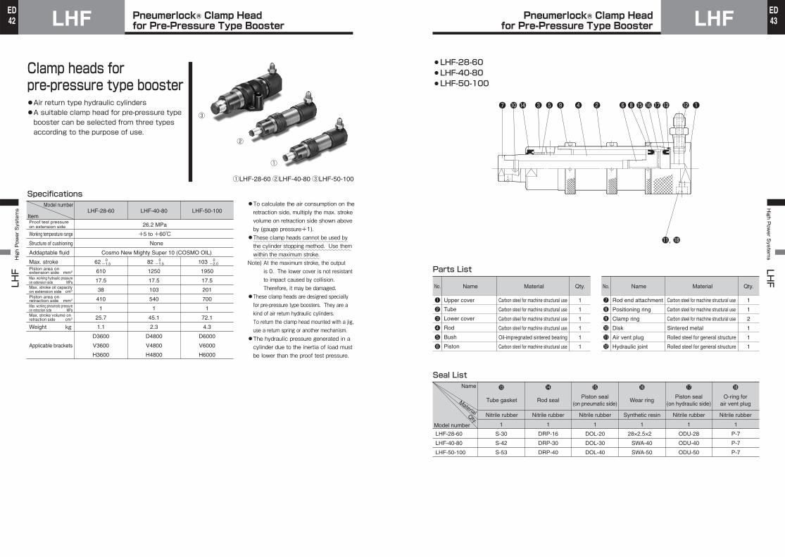
LHF-28-60
LHF-40-80
LHF-50-100
62
82
103
610
1250
1950
17.5
17.5
17.5
38
103
201
410
540
700
1
1
1
25.7
45.1
72.1
0 -1.5
0 -1.5
0 -2.0
Air-oil converters for pre-pressure type booster
Pressure sensors (for high pressure) Pressure gauges
Model number
AHU2-063-001
AHU2-063-002
AHU2-063-004
AHU2-063-006
AHU2-063-010
AHU2-063-016
Oil capacityℓ
0.16
0.25
0.4
0.63
1
1.6
Modelnumber
0882100
0882200
0882300
0882400
Portsize
G1/4
Set pressurerange
0.5 to 7 MPa
1 to 16 MPa
2.5 to 25 MPa
4 to 40 MPa
PG150Q-2
PG250Q-2
PG150Q-2G
PG250Q-2G
R1/4
For 15 MPa
For 25 MPa
For 15 MPa
For 25 MPa
(containingglycerine)
(containingglycerine)
Hydraulic hose
(0.5, 1, 1.5, 2 m)
PBH
Modelnumber
Portsize
Remarks
Clamping ElementClamp heads integral with booster, which can operate with pneumatic pressure and are easy to use because of its reduced size and weight
ItemModelnumber
Nominalstroke mm
Boostingratio
Port sizeG
Theoretical clampingforce at max. working
pneumatic pressure kN
Working pneumaticpressure range
MPa
LE2-3603-03
LE2-3606-03
LE2-3609-03
LE2-4803-08
LE2-4806-08
LE2-4809-08
LE2-4812-08
LE2-4803-12
LE2-6006-18
LE2-6009-18
LE2-6012-18
LE2-6003-21
LE2-6006-21
3
6
9
3
6
9
12
3
6
9
12
3
6
7.84
8.16
16
11
17.36
1/8
1/8
1/8
1/8
1/8
1/8
1/8
1/8
1/4
1/4
1/4
1/4
1/4
3.7
8.3
2.3
18.0
20.8
0.15 to 0.9
0.15 to 0.9
0.15 to 0.7
0.15 to 0.9
0.15 to 0.7
●Use the value obtained by subtracting 1 mm from the nominal stroke as an effective stroke.
Pneumatic Toggle PressSpace-saving pneumatic press.Its volume is 1/10 compared to conventional presses. You can use it with sufficient space around it.
Model numberNominal output Stroke
kN mm C.P.M.
Max. use frequency
TPH-010040
TPH-015040
TPH-020040
9.8
14.7
19.6
40
40
40
60
60
60
●Working fluid: Air Working pressure range: 0.15 to 0.7 MPa
Oil Pack CylinderHigh output of 5 to 30 ton can be obtained only by pneumatic pressure. High output can be maintained for a long time.
ItemModelnumber
Pneumaticcylinderbore mm
Hydrauliccylinderbore mm
Full strokemm
Boosting strokemm
Workingpressure range
MPa
Boostingratio
HSP3F
-100-*-10
HSP3F
-150-*-10
HSP3F
-200-*-10
φ100
φ150
φ200
φ55
φ90
φ110
100
・200
10
44.4
28.7
44.4
0.3 to 0.8
0.5 to 0.8
For Safe UseHigh Power SystemsHigh Power Systems
4ED
For Safe Use High Power SystemsHigh P
ower S
ystems
5ED
●The suitability of pneumatic equipment shall be judged by the person who designs the pneumatic system or determines the specifications.●The equipment shall be handled by persons with sufficient knowledge and experience.Incorrect handling of compressed air can cause hazardous situations. Any machine or device using pneumatic equipment shall be assembled, operated and maintained by persons with sufficient knowledge and experience.●Never handle any machine or device or remove the equipment without ensuring the safety.1)Before inspecting or servicing any machine or device, make sure that the object to be driven is provided with drop or runaway preventing means.
2)Before removing the equipment, make sure that the above safeguard has been provided, and discharge the compressed air in the system.
3)Before restarting any machine or device, make sure that jumping-out preventing measures have been taken.
●Use the product in an environment appropriate to the specifications.If the product is used in any equipment which may considerably affect persons or properties, such as nuclear, railroad, aircraft, vehicle and medical equipment, equipment in contact with drink or food, entertainment equipment, emergency shutoff devices, safeguards for press, brake circuits and safety equipment, particularly for a purpose requiring safety or in an outdoor area, contact us.
*1) ISO 4414: Pneumatic fluid power Recommendations for the applic ation of equipment totransmission control systems
*2) JIS B 8370: General rules of pneumatic system
The safety precautions stated below are to be followed to use the product safely and correctly and to safeguard both you and other persons and avoid property damage. The precautions are classified into three categories, DANGER, WARNING and CAUTION, to indicate the degree of hazard, damage and imminence. Strictly observe these important safety precautions in addition to the safety requirements specified in ISO 4414*1) and JIS B 8370*2) and other standards.
DANGER :
WARNING :
CAUTION :
An imminent hazard which, if not avoided, will result in death or serious injury
A potentially hazardous situation which can result in death or serious injury if the product is improperly handled
A potentially hazardous situation which may result in personal injury or only property damage if the product is improperly handled
WARNING
Common Conditions
●The system shall be handled by persons with sufficient knowledge and experience. Any machine or device using hydraulic and/or pneumatic equipment shall be assembled, operated and maintained by persons with sufficient knowledge and experience.●Do not put the fire close to the equipment.The hydraulic equipment uses flammable hydraulic fluids. Therefore, doing so may cause fire.●Never handle or remove the equipment without ensuring the safety.●Before removing the equipment, make sure that safeguard has been provided, disconnect power from the air pressure source, and make sure that pressure in the hydraulic and pneumatic circuits has been discharged.
●Before inspecting or servicing any machine or device, make sure that the object to be driven is provided with drop preventing means.
●When restarting any machine or device, increase the air pressure source pressure gradually from a low pressure to the set pressure while checking for abnormalities of bolts and other parts.
●If any machine or device may cause personal injury, put a protective cover on it.If the object to be driven or actuator moving parts may cause personal injury, design the machine or device so that human bodies cannot touch directly such a unit.●Surely tighten the fixing and connecting parts of the equipment.●For securing the equipment, use bolts of the specified size and strength class, and tighten the bolts to the specified torque. For rocking mounting accessories, use pins of the specified size. If the bolts are tightened improperly or bolts of improper size are used, the bolts may be loosened or damaged by the cylinder thrust force or its reaction force.
●Use rigid mounting materials.
●When adjusting the air vent, take care not to excessively loosen the air plug.If the air vent plug is excessively loosened, it may come off the cylinder and jump out, and oil may spout out, thereby causing personal injury or malfunction of the actuator.●Examine the action to be taken upon occurrence of emergency stop.If the equipment will be stopped by a safety device when an operator presses the emergency stop button or system trouble is caused by power failure, design the equipment so that the action of the actuator will not cause personal injury or damage the equipment or device.●Check the specifications.●The products shown in the catalog have been designed and manufactured as parts for general industrial machines or iron making machines. The use of any of the products at a pressure or temperature out of the specified range or in an improper operating environment can cause damage to the machine or operation failure. Do not use them under improper conditions.
●For electric parts, such as sensors, sufficiently check the specifications for load current, temperature and impact. The use of the parts under improper conditions can cause operation failure, damage and burnout.
●Never modify the products.Doing so can cause abnormal operation, resulting in personal injury, electric shock and fire.●If the equipment is used under the following conditions, give a sufficient consideration to safety measures, and contact us.●Use under conditions or in an environment not conforming to the indicated specifications or in an outdoor place●Use related to public safety (e.g., nuclear, railroad, aircraft, vehicle and medical equipment, entertainment equipment, emergency shutoff devices, brake circuits and equipment in contact with drink or food)
●Use for safety equipment●Use for purposes specially requiring safety
WARNING
For Safe UseHigh Power SystemsHigh Power Systems
6ED
For Safe Use High Power SystemsHigh P
ower S
ystems
7ED
Notes on air pressure source
取付に関する注意事項
●Use clean compressed air. Compressed air containing chemicals or corrosive gas may damage the equipment or cause operation failure.
CAUTION
●To remove foreign particles in compressed air, install an air filter.●To remove drain in compressed air, install an after-cooler, air dryer and/or air filter.
Notes on use environment
●Do not use the equipment in a corrosive environment. For the cylinder material, see the text.
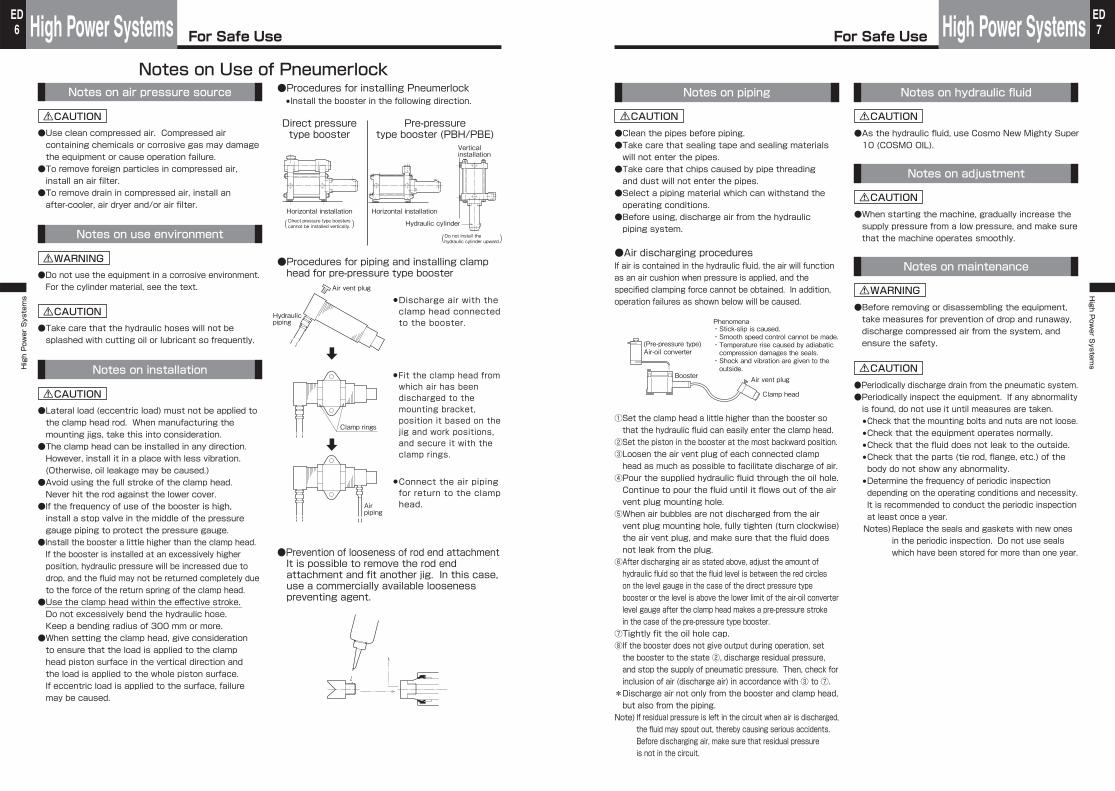
●Procedures for installing Pneumerlock●Install the booster in the following direction.
●Prevention of looseness of rod end attachmentIt is possible to remove the rod end attachment and fit another jig. In this case, use a commercially available looseness preventing agent.
Notes on Use of Pneumerlock
●Take care that the hydraulic hoses will not be splashed with cutting oil or lubricant so frequently.
Notes on installation
●Lateral load (eccentric load) must not be applied to the clamp head rod. When manufacturing the mounting jigs, take this into consideration.●The clamp head can be installed in any direction. However, install it in a place with less vibration. (Otherwise, oil leakage may be caused.)●Avoid using the full stroke of the clamp head.Never hit the rod against the lower cover.●If the frequency of use of the booster is high, install a stop valve in the middle of the pressure gauge piping to protect the pressure gauge.
●Install the booster a little higher than the clamp head. If the booster is installed at an excessively higher position, hydraulic pressure will be increased due to drop, and the fluid may not be returned completely due to the force of the return spring of the clamp head.●Use the clamp head within the effective stroke.Do not excessively bend the hydraulic hose. Keep a bending radius of 300 mm or more.●When setting the clamp head, give consideration to ensure that the load is applied to the clamp head piston surface in the vertical direction and the load is applied to the whole piston surface. If eccentric load is applied to the surface, failure may be caused.
Direct pressuretype booster
Pre-pressuretype booster (PBH/PBE)
●Procedures for piping and installing clamp head for pre-pressure type booster
●Discharge air with the clamp head connected to the booster.
●Connect the air piping for return to the clamp head.
●Fit the clamp head from which air has been discharged to the mounting bracket, position it based on the jig and work positions, and secure it with the clamp rings.
~~~~~~~~~~~~~~~~~~~~~~~~~~~~~~~~~~~~~~~~~~
Horizontal installation Horizontal installation
Hydraulic cylinder
Verticalinstallation
Do not install the hydraulic cylinder upward.
Direct pressure type boosters cannot be installed vertically.
Air vent plug
Hydraulicpiping
Clamp rings
CAUTION
CAUTION
WARNING
Air piping
( )( )
Notes on piping
●Clean the pipes before piping.●Take care that sealing tape and sealing materials will not enter the pipes.●Take care that chips caused by pipe threading and dust will not enter the pipes.●Select a piping material which can withstand the operating conditions.●Before using, discharge air from the hydraulic piping system.
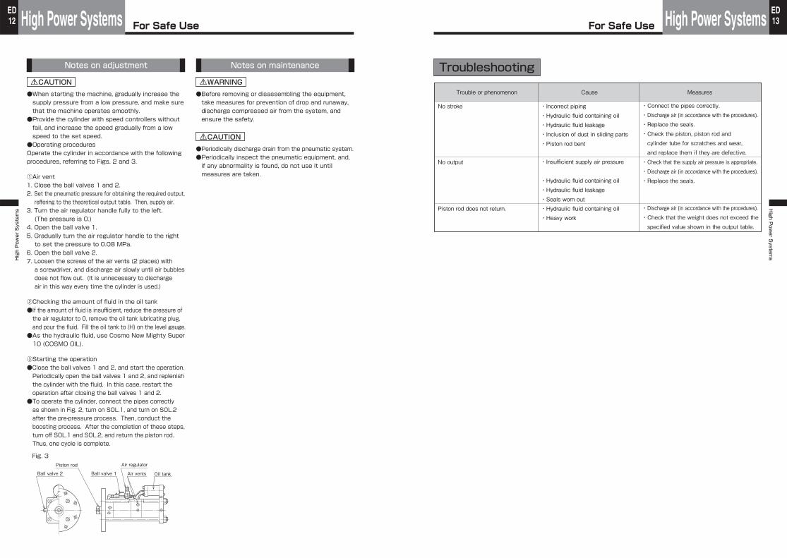
Notes on maintenance
●Before removing or disassembling the equipment, take measures for prevention of drop and runaway, discharge compressed air from the system, and ensure the safety.
●Periodically discharge drain from the pneumatic system.●Periodically inspect the equipment. If any abnormality is found, do not use it until measures are taken.●Check that the mounting bolts and nuts are not loose.●Check that the equipment operates normally.●Check that the fluid does not leak to the outside.●Check that the parts (tie rod, flange, etc.) of the body do not show any abnormality.●Determine the frequency of periodic inspection depending on the operating conditions and necessity. It is recommended to conduct the periodic inspection at least once a year.Notes)Replace the seals and gaskets with new ones
in the periodic inspection. Do not use seals which have been stored for more than one year.
①Set the clamp head a little higher than the booster so that the hydraulic fluid can easily enter the clamp head.②Set the piston in the booster at the most backward position.③Loosen the air vent plug of each connected clamp head as much as possible to facilitate discharge of air.④Pour the supplied hydraulic fluid through the oil hole. Continue to pour the fluid until it flows out of the air vent plug mounting hole.⑤When air bubbles are not discharged from the air vent plug mounting hole, fully tighten (turn clockwise) the air vent plug, and make sure that the fluid does not leak from the plug.⑥After discharging air as stated above, adjust the amount of hydraulic fluid so that the fluid level is between the red circles on the level gauge in the case of the direct pressure type booster or the level is above the lower limit of the air-oil converter level gauge after the clamp head makes a pre-pressure stroke in the case of the pre-pressure type booster.
⑦Tightly fit the oil hole cap.⑧If the booster does not give output during operation, set the booster to the state ②, discharge residual pressure, and stop the supply of pneumatic pressure. Then, check for inclusion of air (discharge air) in accordance with ③ to ⑦.*Discharge air not only from the booster and clamp head, but also from the piping.
Note) If residual pressure is left in the circuit when air is discharged, the fluid may spout out, thereby causing serious accidents.Before discharging air, make sure that residual pressure is not in the circuit.
Notes on adjustment
●When starting the machine, gradually increase the supply pressure from a low pressure, and make sure that the machine operates smoothly.
●Air discharging proceduresIf air is contained in the hydraulic fluid, the air will function as an air cushion when pressure is applied, and the specified clamping force cannot be obtained. In addition, operation failures as shown below will be caused.
(Pre-pressure type)Air-oil converter
Booster Air vent plug
Phenomena・Stick-slip is caused.・Smooth speed control cannot be made.・Temperature rise caused by adiabatic compression damages the seals.
・Shock and vibration are given to the outside.
Clamp head
CAUTION
WARNING
CAUTION
CAUTION
Notes on hydraulic fluid
●As the hydraulic fluid, use Cosmo New Mighty Super 10 (COSMO OIL).
CAUTION
For Safe UseHigh Power SystemsHigh Power Systems
8ED
For Safe Use High Power SystemsHigh P
ower S
ystems
9ED
Notes on air pressure source
●Use clean compressed air. Compressed air containing chemicals or corrosive gas may damage the equipment or cause operation failure.●To remove foreign particles in compressed air, install an air filter.●To remove drain in compressed air, install an after-cooler, air dryer and/or air filter.
Notes on use environment
●Do not use the equipment in a corrosive environment. For the cylinder material, see the text.
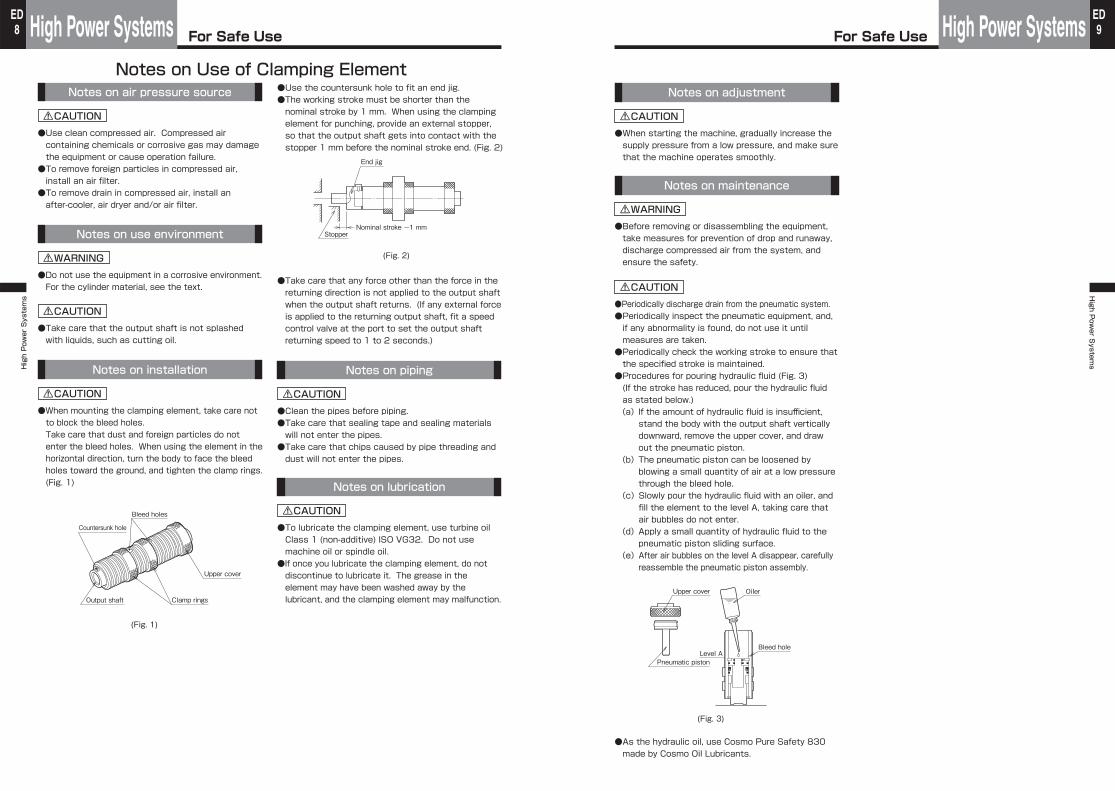
●Use the countersunk hole to fit an end jig.●The working stroke must be shorter than the nominal stroke by 1 mm. When using the clamping element for punching, provide an external stopper, so that the output shaft gets into contact with the stopper 1 mm before the nominal stroke end. (Fig. 2)
Notes on Use of Clamping Element
●Take care that the output shaft is not splashed with liquids, such as cutting oil.
Notes on installation
●When mounting the clamping element, take care not to block the bleed holes.Take care that dust and foreign particles do not enter the bleed holes. When using the element in the horizontal direction, turn the body to face the bleed holes toward the ground, and tighten the clamp rings. (Fig. 1)
●Take care that any force other than the force in the returning direction is not applied to the output shaft when the output shaft returns. (If any external force is applied to the returning output shaft, fit a speed control valve at the port to set the output shaft returning speed to 1 to 2 seconds.)
Notes on piping
●Clean the pipes before piping.●Take care that sealing tape and sealing materials will not enter the pipes.●Take care that chips caused by pipe threading and dust will not enter the pipes.
Notes on lubrication
●To lubricate the clamping element, use turbine oil Class 1 (non-additive) ISO VG32. Do not use machine oil or spindle oil.
●If once you lubricate the clamping element, do not discontinue to lubricate it. The grease in the element may have been washed away by the lubricant, and the clamping element may malfunction.
Countersunk hole
Bleed holes
Output shaft
(Fig. 1)
Clamp rings
Upper cover
End jig
(Fig. 2)
StopperNominal stroke -1 mm
WARNING
CAUTION
CAUTION
CAUTION CAUTION
CAUTION
Notes on maintenance
●Before removing or disassembling the equipment, take measures for prevention of drop and runaway, discharge compressed air from the system, and ensure the safety.
●Periodically discharge drain from the pneumatic system.●Periodically inspect the pneumatic equipment, and, if any abnormality is found, do not use it until measures are taken.●Periodically check the working stroke to ensure that the specified stroke is maintained.●Procedures for pouring hydraulic fluid (Fig. 3) (If the stroke has reduced, pour the hydraulic fluid as stated below.)(a)If the amount of hydraulic fluid is insufficient,
stand the body with the output shaft vertically downward, remove the upper cover, and draw out the pneumatic piston.
(b)The pneumatic piston can be loosened by blowing a small quantity of air at a low pressure through the bleed hole.
(c)Slowly pour the hydraulic fluid with an oiler, and fill the element to the level A, taking care that air bubbles do not enter.
(d)Apply a small quantity of hydraulic fluid to the pneumatic piston sliding surface.
(e)After air bubbles on the level A disappear, carefully reassemble the pneumatic piston assembly.
Notes on adjustment
●When starting the machine, gradually increase the supply pressure from a low pressure, and make sure that the machine operates smoothly.
●As the hydraulic oil, use Cosmo Pure Safety 830 made by Cosmo Oil Lubricants.
Pneumatic piston
Upper cover Oiler
Level ABleed hole
(Fig. 3)
WARNING
CAUTION
CAUTION

For Safe UseHigh Power SystemsHigh Power Systems
10ED
For Safe Use High Power SystemsHigh P
ower S
ystems
11ED
●Use clean compressed air. Compressed air containing chemicals or corrosive gas may damage the equipment or cause operation failure.●To remove foreign particles in compressed air, install an air filter.●To remove drain in compressed air, install an after-cooler, air dryer and/or air filter.
●Do not use the equipment in a corrosive environment. For the cylinder material, see the text.
Notes on Use of Toggle Press
●If the press is used in a place with much dust or exposed to water drops or oil drops, cover the piston rod.
●When connecting, align the ram shaft center with the moving direction.
●Clean the pipes before piping.●Take care that sealing tape and sealing materials will not enter the pipes.●Take care that chips caused by pipe threading and dust will not enter the pipes.
●For lubrication, use turbine oil Class 1 (non-additive) ISO VG32. Do not use machine oil or spindle oil.
●Note that the use of toggle press under a load higher than the nominal output may reduce its durability.●Take care not to apply lateral load or eccentric load to the ram.
●If the load is removed in the middle of ram stroke, for example, in the case of punching or cutting, use the press with the following load rate for each working pneumatic pressure. If a load rate with too large allowance is selected, the internal piston will give an excessive shock to the body after the completion of working, thereby damaging the bolts or body. 0.5 MPa…90% 0.6 MPa…80% 0.7 MPa…75%●The load must be within 4 mm from the bottom dead center.●If backlash caused by rotation of the ram is unfavorable for the purpose of use, contact us.
●Before removing or disassembling the equipment, take measures for prevention of drop and runaway, discharge compressed air from the system, and ensure the safety.
●Periodically discharge drain from the pneumatic system.●Periodically inspect the pneumatic equipment, and, if any abnormality is found, do not use it until measures are taken.
●When starting the machine, gradually increase the supply pressure from a low pressure, and make sure that the machine operates smoothly.
Notes on air pressure source
Notes on use environment
Notes on installation
Notes on piping
Notes on lubrication
Notes on design
Notes on maintenance
Notes on adjustment
CAUTION
WARNING
WARNING
CAUTION
CAUTION
CAUTION
CAUTION
CAUTION
CAUTION
CAUTION
●Use clean compressed air. Compressed air containing chemicals or corrosive gas may damage the equipment or cause operation failure.●To remove foreign particles in compressed air, install an air filter.●To remove drain in compressed air, install an after-cooler, air dryer and/or air filter.
●Do not use the equipment in a corrosive environment. For the cylinder material, see the text.
●Connect the cylinder aligning the rod shaft center with the moving direction.●Be sure to use the cylinder with the piston rod downward or horizontal. (Fig. 1)
●If the cylinder is operated to the stroke end for boosting, the output is zero at the stroke end. Use the cylinder within the range of 〔stroke-1〕 mm. If the load is removed in the middle of stroke, for example, in the case of punching, provide an external stopper without fail.
●If a jig or a heavy article is fitted to the end of the piston rod, the returning force is reduced. Therefore, in such a case, return the rod with external force of a spring, etc.
●Clean the pipes before piping.●Take care that sealing tape and sealing materials will not enter the pipes.●Take care that chips caused by pipe threading and dust will not enter the pipes.●Connect the oil pack cylinder and the directional control valves as shown in Fig. 2.
●For lubrication, use turbine oil Class 1 (non-additive) ISO VG32. Do not use machine oil or spindle oil.
●Set the directional control valves to feed air to the following portsPre-pressure process : A2Boosting process : A2 and A4Stopping and returning : A1 and A3●Install the speed controllers for controlling the piston rod advancing speed to set the port A1 to the meter-out control and the port A2 to the meter-in control. For controlling the piston rod returning speed, install the speed controller to set the port A4 to the meter-out control.
Fig. 1
Fig. 2
A1 A2 A3 A4
SOL.2SOL.1
Speed controller
Solenoid valve
Air control unit
Notes on Use of Oil Pack Cylinder
WARNING
CAUTION
CAUTION
CAUTION
CAUTION
CAUTION
Notes on air pressure source
Notes on use environment
Notes on installation
Notes on design Notes on piping
Notes on lubrication
For Safe UseHigh Power SystemsHigh Power Systems
12ED
For Safe Use High Power SystemsHigh P
ower S
ystems
13ED
●Before removing or disassembling the equipment, take measures for prevention of drop and runaway, discharge compressed air from the system, and ensure the safety.
●Periodically discharge drain from the pneumatic system.●Periodically inspect the pneumatic equipment, and, if any abnormality is found, do not use it until measures are taken.
●When starting the machine, gradually increase the supply pressure from a low pressure, and make sure that the machine operates smoothly.●Provide the cylinder with speed controllers without fail, and increase the speed gradually from a low speed to the set speed.●Operating proceduresOperate the cylinder in accordance with the following procedures, referring to Figs. 2 and 3.
①Air vent1. Close the ball valves 1 and 2.2. Set the pneumatic pressure for obtaining the required output, reffering to the theoretical output table. Then, supply air.
3. Turn the air regulator handle fully to the left. (The pressure is 0.)
4. Open the ball valve 1.5. Gradually turn the air regulator handle to the right to set the pressure to 0.08 MPa.
6. Open the ball valve 2.7. Loosen the screws of the air vents (2 places) with a screwdriver, and discharge air slowly until air bubbles does not flow out. (It is unnecessary to discharge air in this way every time the cylinder is used.)
②Checking the amount of fluid in the oil tank●If the amount of fluid is insufficient, reduce the pressure of the air regulator to 0, remove the oil tank lubricating plug, and pour the fluid. Fill the oil tank to (H) on the level gauge.
●As the hydraulic fluid, use Cosmo New Mighty Super 10 (COSMO OIL).
③Starting the operation●Close the ball valves 1 and 2, and start the operation.Periodically open the ball valves 1 and 2, and replenish the cylinder with the fluid. In this case, restart the operation after closing the ball valves 1 and 2.
●To operate the cylinder, connect the pipes correctly as shown in Fig. 2, turn on SOL.1, and turn on SOL.2 after the pre-pressure process. Then, conduct the boosting process. After the completion of these steps, turn off SOL.1 and SOL.2, and return the piston rod. Thus, one cycle is complete.
Fig. 3
Ball valve 2 Ball valve 1
Piston rod
Air vents Oil tank
Air regulator
WARNING
CAUTION
CAUTION
Notes on maintenanceNotes on adjustment
Trouble or phenomenon Cause Measures
No stroke
No output
Piston rod does not return.
・Incorrect piping・Hydraulic fluid containing oil・Hydraulic fluid leakage・Inclusion of dust in sliding parts・Piston rod bent
・Insufficient supply air pressure
・Hydraulic fluid containing oil・Hydraulic fluid leakage・Seals worn out・Hydraulic fluid containing oil・Heavy work
・Connect the pipes correctly.・Discharge air (in accordance with the procedures).・Replace the seals.・Check the piston, piston rod and cylinder tube for scratches and wear, and replace them if they are defective.・Check that the supply air pressure is appropriate.・Discharge air (in accordance with the procedures).・Replace the seals.
・Discharge air (in accordance with the procedures).・Check that the weight does not exceed the specified value shown in the output table.
Troubleshooting

High Power Systems H
igh Power S
ystems
Clamp Heads............
Oil-Air Converters for Pre-pressure Type Booster..ED39
Clamp Heads for Pre-pressure Type Booster
Direct Pressure Type Boosters .. Pre-pressure Type Boosters..ED32
Pneumerlock®
Fittings and Hydraulic Hoses..
ED24
ED40 ..ED42 ED46
Pneumerlock®High Power Systems
16ED
Pneumerlock®High P
ower S
ystems
17ED
Modelnumber
Max. strokemm
Pistonarea on
retractionside mm2
Pistonarea on
retractionside mm2
Max. workinghydraulic
pressure onextension side
MPa
Max. strokeoil capacity
on extensionside cm3
Max. workingpneumatic
pressure onretraction side
MPa
Max. strokevolume onretractionside cm3
Model numberWorking pneumatic
pressure rangeMPa
Boostingratio
Theoretical output oil pressure at max. working pneumatic pressure MPa
Discharge oilcapacity
cm3
①Direct pressure type booster
11
25
25
25
25
11
17.5
17.5
17.5
17.5
77
77
130
176
304
The *-marked models cannot be provided with sensors.
PBH3-40, PBE3-40
PBH3-60, PBE3-60
*PBH-80, *PBE-80
0.2 to 1
0.2 to 0.7
0.2 to 0.7
11
25
25
11
17.5
17.5
77
77
176
The *-marked models cannot be provided with sensors.
LHD
LHC
LHA
LHA-25
LHA-40
LHAS-2
6
7
12
24
38
20
570
1340
1460
1460
1460
2640
4
10.7
19
36.5
58.4
60.7
LHF-28-60
LHF-40-80
LHF-50-100
62
82
103
610
1250
1950
17.5
17.5
17.5
38
103
201
410
540
700
1
1
1
25.7
45.1
72.1
0 -1.5 0 -1.5 0 -2.0
Direct pressure type booster configuration
②Pre-pressure type booster
③Clamp heads
④Clamp heads for pre-pressure type booster
①Direct pressure type booster⑦Pressuresensor
⑧Pressuregauge
⑤Fitting
⑤Hydraulic hose ③Clamp head
Model numberWorking pneumatic
pressure rangeMPa
Boostingratio
Theoretical output oil pressure at max. working pneumatic pressure MPa
Discharge oilcapacity
cm3
NBH3-40
NBH3-60
NBH3-60-130
*NBH-80
*NBH-100
0.2 to 1
0.2 to 0.7
0.2 to 0.7
0.2 to 0.7
0.2 to 0.7
Model numberEffective stroke Piston pressure
receiving areamm2mm
Max. stroke volume
cm3
⑤Fittings and hydraulic hoses
Pre-pressure type booster configuration
Hydraulic hoses
(0.5, 1, 1.5, 2 m)
⑥Air-oil converters for pre-pressure type booster
AHU2-063-001
AHU2-063-002
AHU2-063-004
AHU2-063-006
AHU2-063-010
AHU2-063-016
0.16
0.25
0.4
0.63
1
1.6
⑦Pressure sensors (for high pressure) ⑧Pressure gauges
As related products, compact design hydraulic cylinders are applicable.See the general catalog of hydraulic equipment.
0882100
0882200
0882300
0882400
G1/4
PG150Q-2
PG250Q-2
PG150Q-2G
PG250Q-2G
R1/4
②Pre-pressure type booster
⑥Air-oil converter for pre-pressure type booster
⑤Fitting
⑤Hydraulic hoses
④Clamp head for pre-pressure type booster
⑦Pressuresensor
⑧Pressuregauge
Model numberOil capacity
ℓ
Modelnumber
Portsize
Set pressurerange
Modelnumber
Portsize
Remarks
0.5 to 7 MPa
1 to 16 MPa
4 to 40 MPa
2.5 to 25 MPa
For 15 MPa
For 25 MPa
For 15 MPa
For 25 MPa
(containingglycerine)
(containingglycerine)
Outline of Models Outline of Models
Pneumerlock®High Power Systems
18ED
Pneumerlock®High P
ower S
ystems
19ED
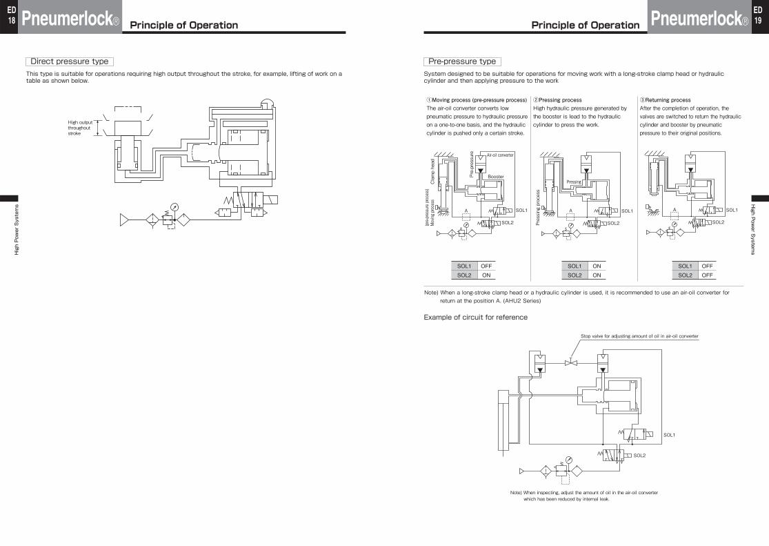
Direct pressure typeThis type is suitable for operations requiring high output throughout the stroke, for example, lifting of work on a table as shown below.
High output throughout stroke
①Moving process (pre-pressure process)The air-oil converter converts low pneumatic pressure to hydraulic pressure on a one-to-one basis, and the hydraulic cylinder is pushed only a certain stroke.
②Pressing processHigh hydraulic pressure generated by the booster is lead to the hydraulic cylinder to press the work.
③Returning processAfter the completion of operation, the valves are switched to return the hydraulic cylinder and booster by pneumatic pressure to their original positions.
SOL1
SOL2
OFF
ON
SOL1
SOL2
ON
ON
SOL1
SOL2
OFF
OFF
Example of circuit for reference
SOL1
Stop valve for adjusting amount of oil in air-oil converter
Note) When inspecting, adjust the amount of oil in the air-oil converter which has been reduced by internal leak.
SOL2
Clamp he
ad(pre-pressure proc
ess)
Moving
proce
ss
Pre-pressure Air-oil converter
Booster
A SOL1
SOL2 Pressing proc
ess
Pressing
A SOL1
SOL2
A SOL1
SOL2
Note) When a long-stroke clamp head or a hydraulic cylinder is used, it is recommended to use an air-oil converter for return at the position A. (AHU2 Series)
Pre-pressure typeSystem designed to be suitable for operations for moving work with a long-stroke clamp head or hydraulic cylinder and then applying pressure to the work
Principle of Operation Principle of Operation
Pneumerlock®High Power Systems
20ED
Pneumerlock®High P
ower S
ystems
21ED
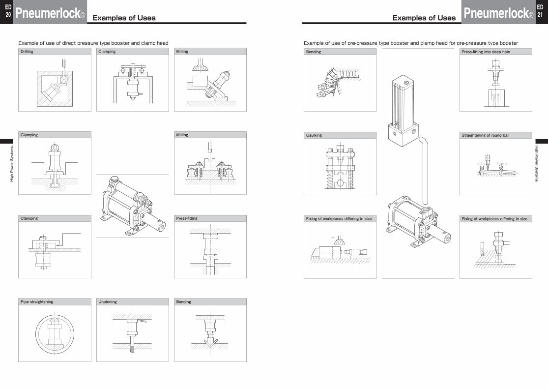
Example of use of direct pressure type booster and clamp headDrilling Clamping Milling
Clamping Milling
Clamping Press-fitting
Pipe straightening Unpinning Bending
Example of use of pre-pressure type booster and clamp head for pre-pressure type booster
Bending Press-fitting into deep hole
Caulking Straightening of round bar
Fixing of workpieces differing in size Fixing of workpieces differing in size
Examples of Uses Examples of Uses
Pneumerlock®High Power Systems
22ED
Pneumerlock®High P
ower S
ystems
23ED
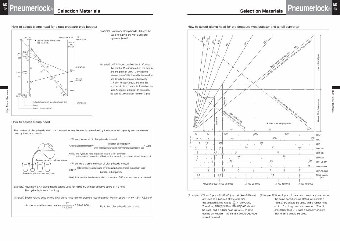
How to select clamp head for direct pressure type booster〈Example〉How many clamp heads LHA can be
used for NBH3-60 with a 2m long hydraulic hose?
〈Answer〉LHA is shown on the side A. Connect the point of 2 m indicated on the side A and the point of LHA. Connect the intersection of this line with the relation line X with the booster oil capacity (77 cm³ for NBH3-60), and find the number of clamp heads indicated on the side A, approx. 2.8 pcs. In this case, be sure to use a lower number, 2 pcs.
How to select clamp head
The number of clamp heads which can be used for one booster is determined by the booster oil capacity and the volume used by the clamp heads.
・When one model of clamp heads is used
Number of usable clamp heads= ×0.85booster oil capacity
stroke volume used by one clamp head+hydraulic hose expansion loss
Notes) The hydraulic hose expansion loss is 5 cm³ per meter.In the case of connection with pipes, the expansion loss is not taken into account.
・When more than one model of clamp heads is used
0.85>total stroke volume used by all clamp heads+total expansion loss
booster oil capacity
Note) If the result of the above calculation is less than 0.85, the clamp heads can be used.
〈Example〉How many LHA clamp heads can be used for NBH3-60 with an effective stroke of 12 mm? The hydraulic hose is 1 m long.
〈Answer〉Stroke volume used by one LHA clamp head=piston pressure receiving area×working stroke=14.6×1.2=17.52 cm3
Up to two clamp heads can be used.Number of usable clamp heads= ×0.85=2.906…77
17.52+5
(A) (B) 40
(A) Relation line X
●Use the values on the same side (A) or (B).
(B) LHF-50-100
LHF-40-80
LHAS-2LHA-40
30NBH3
-40 NBH3
-60
NBH -80
NBH -100
20
10
5
Hydraulic hose length (per clamp head) (m) Clamp head
Booster oil capacity (cm³)
Booster
10
8
LHF-28 -60
LHA-25
LHA
LHC
LHD
7
5
4
2
1
0.5
2
1
1(B)
2
3
45
10
3
4
(A)5
10
20
50
100
0
100
200
300
(77)
(176)
(304)
Number of clamp heads
Stroke volume used by clamp head
Booster hydraulic cylinder volume
How to select clamp head for pre-pressure type booster and air-oil converter
〈Example 1〉When 5 pcs. of LHA-40 (max. stroke of 40 mm) are used at a boosted stroke of 8 mm, the boosted stroke rate is ×100=20%. Therefore, PBH(E)3-40 or PBH(E)3-60 should be used, and a rubber hose up to 2.6 m long can be connected. The oil tank AHU2-063-006 should be used.
〈Example 2〉When 7 pcs. of the clamp heads are used under the same conditions as stated in Example 1, PBH(E)-80 should be used, and a rubber hose up to 16 m long can be connected. The oil ank AHU2-063-010 with a capacity of more than 0.56 ℓ should be used.
Rubber hose length (total)
100%
70%
50%
40%
30% 20% 15%
Boosted stroke u
sage rate
10%
(Select with
10% e
ven wh
en the
booster i
s used
at a ra
te of le
ss tha
n 10%
.)
Use
of P
BH
(E)-
80
PBH(E)-80, Rubber hose length auxiliary line Use
of P
BH
(E)3
-40
or 6
0
PBH(E)3-40,60
Rubber hose length auxiliary line
Example 2
Num
ber
Example 1
1 5 10
10 50 100
5 10 20
5 10 20 50
50 100 150LHD
LHC
LHA
LHA-25
LHA-40
LHAS-2
LHF-28-60
AHU2-100-020AHU2-100-016AHU2-063-010AHU2-063-006AHU2-063-002
LHF-40-80
LHF-50-100
Oil tank capacity(ℓ)
4030201051
10 2051
10 2051
10 20 3051
10 1551
6 7
1.50.50.1 1 2
541 2 3
200 300
20 30
408
Selection Materials Selection Materials
NBHNBH High Power Systems
24ED
NBHHigh P
ower S
ystems NBH
25ED
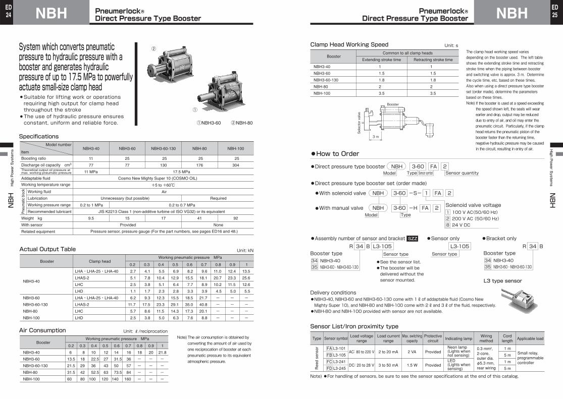
System which converts pneumatic pressure to hydraulic pressure with a booster and generates hydraulic pressure of up to 17.5 MPa to powerfully actuate small-size clamp head¡Suitable for lifting work or operations requiring high output for clamp head throughout the stroke
¡The use of hydraulic pressure ensures constant, uniform and reliable force.
Specifications
Actual Output Table Unit: kN
Model number
Item
Boosting ratio
Discharge oil capacity cm3
Theoretical output oil pressure at max. working pneumatic pressure
Addaptable fluid
Working temperature range
Pneu
mat
ic b
lock
Working fluid
Lubrication Working pressure range
Recommended lubricant
Weight kg
With sensor
Related equipment
NBH3-40
11
77
11 MPa
NBH3-60 NBH3-60-130 NBH-80 NBH-100
25
77
25
130
25
176
25
304
17.5 MPa
Cosmo New Mighty Super 10 (COSMO OIL)
+5 to +60℃ Air
Unnecessary (but possible) Required
0.2 to 0.7 MPa0.2 to 1 MPa
JIS K2213 Class 1 (non-additive turbine oil ISO VG32) or its equivalent
9.5 15 17 41 92
Provided None
Pressure sensor, pressure gauge (For the part numbers, see pages ED16 and 48.)
NBH3-40
NBH3-60
NBH3-60-130
NBH-80
NBH-100
Clamp headBooster
LHA・LHA-25・LHA-40
LHAS-2
LHC
LHD
LHA・LHA-25・LHA-40
LHAS-2
LHC
LHD
0.2
2.7
5.1
2.5
1.1
6.2
11.7
5.7
2.5
0.3
4.1
7.8
3.8
1.7
9.3
17.5
8.6
3.8
0.4
5.5
10.4
5.1
2.3
12.3
23.3
11.5
5.0
0.5
6.9
12.9
6.4
2.8
15.5
29.1
14.3
6.3
0.6
8.2
15.5
7.7
3.3
18.5
35.0
17.3
7.6
0.7
9.6
18.1
8.9
3.9
21.7
40.8
20.1
8.8
0.8
11.0
20.7
10.2
4.5
- - - -
0.9
12.4
23.3
11.5
5.0
- - - -
1
13.5
25.6
12.6
5.5
- - - -
Working pneumatic pressure MPa
①NBH3-60 ②NBH-80
①
②
Note) The air consumption is obtained by converting the amount of air used by one reciprocation of booster at each pneumatic pressure to its equivalent atmospheric pressure.
Air Consumption Unit: ℓ/reciprocation
NBH3-40
NBH3-60
NBH3-60-130
NBH-80
NBH-100
Working pneumatic pressure MPa
0.2
6
13.5
21.5
31.5
60
0.3
8
18
29
42
80
0.4
10
22.5
36
52.5
100
0.5
12
27
43
63
120
0.6
14
31.5
50
73.5
140
0.7
16
36
57
84
160
0.8
18
- - - -
0.9
20
- - - -
1
21.8
- - - -
Booster
The clamp head working speed varies depending on the booster used. The left table shows the extending stroke time and retracting stroke time when the piping between booster and switching valve is approx. 3 m. Determine the cycle time, etc. based on these times. Also when using a direct pressure type booster set (order made), determine the parameters based on these times.Note) If the booster is used at a speed exceeding
the speed shown left, the seals will wear earlier and drop, output may be reduced due to entry of air, and oil may enter the pneumatic circuit. Particularly, if the clamp head returns the pneumatic piston of the booster faster than the returning time, negative hydraulic pressure may be caused in the circuit, resulting in entry of air.
Clamp Head Working Speed Unit: s
NBH3-40
NBH3-60
NBH3-60-130
NBH-80
NBH-100
Common to all clamp heads
Extending stroke time Retracting stroke time
1
1.5
1.8
2
3.5
1
1.5
1.8
2
3.5
Booster
●How to Order
FA L3-101
FB L3-105
FC L3-241
FD L3-245
Sensor symbolMax. switching
capacityLoad voltage
rangeLoad current
rangeCord
length Applicable loadType
Ree
d se
nsor
AC: 80 to 220 V
DC: 20 to 28 V
2 to 20 mA
3 to 50 mA
2 VA
1.5 W
Protectivecircuit Indicating lamp
Wiringmethod
Provided
Provided
Neon lamp(Lights whennot sensing)LED(Lights when sensing)
0.3 mm², 2-core, outer dia. φ5.3 mm, rear wiring
1 m
5 m
1 m
5 m
Small relay, programmable controller
Sensor List/Iron proximity type
Note) ●For handling of sensors, be sure to see the sensor specifications at the end of this catalog.
●Direct pressure type booster set (order made)
Delivery conditions●NBH3-40, NBH3-60 and NBH3-60-130 come with 1 ℓ of addaptable fluid (Cosmo New Mighty Super 10), and NBH-80 and NBH-100 come with 2 ℓ and 3 ℓ of the fluid, respectively.
●NBH-80 and NBH-100 provided with sensor are not available.
Model Type
Model
●With solenoid valve NBH 3-60 -S- 1 FA 2
Type●With manual valve NBH 3-60 -H FA 2
1 100 V AC(50/60 Hz)2 200 V AC (50/60 Hz)8 24 V DC
Solenoid valve voltage
R 34 B L3-105
34 NBH3-4035 NBH3-60・NBH3-60-130
Booster type Sensor type
●See the sensor list.●The booster will be delivered without the sensor mounted. L3 type sensor
●Direct pressure type booster NBH 3-60 FA 2
●Assembly number of sensor and bracket SZZ
Booster
3 m
Selector valve
Sensor symbol Sensor quantity
L3-105Sensor type
●Sensor only SZZ
34 NBH3-4035 NBH3-60・NBH3-60-130
Booster typeR 34 B
●Bracket only SZZ
Pneumerlock® Direct Pressure Type Booster
Pneumerlock® Direct Pressure Type Booster
NBHNBH High Power Systems
26ED
NBHHigh P
ower S
ystems NBH
27EDPneumerlock®
Direct Pressure Type BoosterPneumerlock®
Direct Pressure Type BoosterUnit: mm Unit: mm
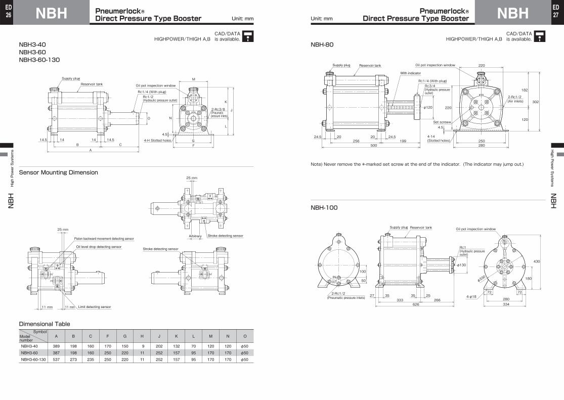
NBH3-40NBH3-60NBH3-60-130
Sensor Mounting Dimension
A
389
387
537
B
198
198
273
C
160
160
235
F
170
250
250
G
150
220
220
H
9
11
11
J
202
252
252
K
132
157
157
L
70
95
95
M
120
170
170
N
120
170
170
O
φ50
φ50
φ50
NBH3-40
NBH3-60
NBH3-60-130
SymbolModel number
Dimensional Table
Supply plugReservoir tank
RC1/4 (With plug)
Oil pot inspection window
M
14.5 14.514 14B C
A
RC1/2 (Hydraulic pressure outlet)
O N
4.5
4-H Slotted holes GF
L
K
J2-RC3/8(Pneumatic pressure inlets)
11 mm 11 mm
25 mm
25 mm
Limit detecting sensor
Stroke detecting sensor
Stroke detecting sensorOil level drop detecting sensor
Piston backward movement detecting sensorArbitrary
Note) Never remove the *-marked set screw at the end of the indicator. (The indicator may jump out.)
NBH-80
NBH-100
25624.5 24.520 20
φ120
199500
250
220Oil pot inspection windowReservoir tankSupply plug
220
280
120
182
3022-Rc1/2 (Air inlets)
RC1/4 (With plug)
With indicator
4-14 (Slotted holes)
Set screw*4.5
3527 2535
626333 266
72 72
280334
180
430φ130
φ330
Oil pot inspection windowSupply plug Reservoir tank
4-φ18
100
50INOUT
2-RC1/2
RC1(Hydraulic pressure outlet)
(Pneumatic pressure inlets)
RC3/4 (Hydraulic pressure outlet)
CAD/DATAis available.HIGHPOWER/THIGH A,B
CAD/DATAis available.HIGHPOWER/THIGH A,B
NBHNBH High Power Systems
28ED
NBHHigh P
ower S
ystems NBH
29EDPneumerlock® Direct Pressure Type
Booster Set (Order Made)Pneumerlock® Direct Pressure Type
Booster Set (Order Made)Unit: mm
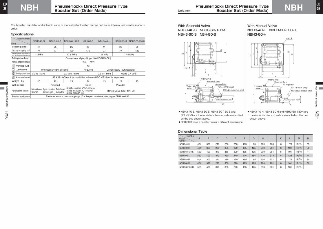
Specifications
The booster, regulator and solenoid valve or manual valve located on one bed as an integral unit can be made to order.
NBH3-40-S
11
77
11 MPa
NBH3-60-S
25
77
NBH3-60-130-S
25
130
NBH-80-S
25
176
NBH3-40-H
11
77
11 MPa
NBH3-60-H
25
77
NBH3-60-130-H
25
130
Model number
Item
17.5 MPa 17.5 MPa
Cosmo New Mighty Super 10 (COSMO OIL)
+5 to +60℃ Air
RequiredUnnecessary (but possible) Unnecessary (but possible)
0.2 to 1 MPa 0.2 to 0.7 MPa 0.2 to 1 MPa 0.2 to 0.7 MPa
JIS K2213 Class 1 (non-additive turbine oil ISO VG32) or its equivalent
15 22 25 54
None
15 22 25
Provided Provided
Pressure sensor, pressure gauge (For the part numbers, see pages ED16 and 48.)
Manual valve type: 4PN-20Solenoid valve5ER-08E
5-port 2-position air return type
Rated power supply type
5ER-8E-10S4(100 V AC/DC・50/60 Hz) :5ER-8E-20S4(200 V AC・50/60 Hz) 5ER-8E-24S4(24 V DC)
Boosting ratio
Discharge oil capacity cm3
Theoretical output oil pressure at max. working pneumatic pressure
Addaptable fluid
Working temperature range
Pneu
mat
ic b
lock Working fluid
Lubrication
Working pressure range
Recommended lubricant
Weight kg
With sensor
Applicable valve
Related equipment
⎞⎟⎠
⎞⎟
⎠
With Solenoid ValveNBH3-40-S NBH3-60-130-SNBH3-60-S NBH-80-S
With Manual ValveNBH3-40-H NBH3-60-130-HNBH3-60-H
Dimensional Table
●NBH3-40-S, NBH3-60-S, NBH3-60-130-S and NBH-80-S are the model numbers of sets assembled on the bed shown above.●NBH-80-S uses a booster having a different appearance.
●NBH3-40-H, NBH3-60-H and NBH3-60-130H are the model numbers of sets assembled on the bed shown above.
A
404
404
553
520
404
404
553
B
300
320
400
400
300
320
400
C
270
290
370
370
270
290
370
D
286
356
356
430
286
356
356
E
250
320
320
440
250
320
320
F
165
195
195
275
165
195
195
G
85
125
125
165
85
125
125
H
220
290
290
410
220
290
290
J
208
261
261
313
221
261
261
K
6
6
6
8
6
6
6
L
76
101
101
128
76
101
101
M
Rc1/2
Rc1/2
Rc1/2
Rc3/4
Rc1/2
Rc1/2
Rc1/2
N
35
30
- - 35
30
-
NBH3-40-S
NBH3-60-S
NBH3-60-130-S
NBH-80-S
NBH3-40-H
NBH3-60-H
NBH3-60-130-H
SymbolModel number
D E H
CBAN
J
L
K
G
F
4-φ14
Solenoidvalve
Supply plugReservoir tank
Air regulator
M (Hydraulic pressure outlet)Rc1/4 (With plug)
Rc3/8 (Pneumatic pressure inlet)
J
L
K
Manual valve
Air regulator
D E H
CBAN
G
F
4-φ14
M (Hydraulic pressure outlet)Rc1/4 (With plug)
Rc3/8 (Pneumatic pressure inlet)
Supply plugReservoir tank

NBHNBH High Power Systems
30ED
NBHHigh P
ower S
ystems NBH
31ED
●NBH-80
●NBH-100
●NBH3-40/NBH3-60/NBH3-60-130
❸❹ ❻17 18 2619 13 22 18 26 27 23 24 14 25 16
❷ ❺ ❶12
17 18 26 19 13 26
15
❹ ❸ ❽ 14 21 24 ❾ ❻
12
18 17 26 19 13 18
❷
❹ ❸
12 22❷ ❺ ❶ 25 24 11 ❼
142829 24❻
22 23❺ ❶ 25 11 ❼
Parts List
No.
❶❷
❸
❹❺❻❼❽❾1112
13
14151617
Name
Hydraulic cylinder mounting cover
Pneumatic cylinder cover
Pneumatic cylinder tube
Pneumatic piston
Hydraulic piston
Hydraulic cylinder tube
Hydraulic cap cover
Indicator rod
Indicator pipe
Hydraulic tie rod
Pneumatic tie rod
Reservoir tube
Oil pot
Flange
Ring
Supply plug
Material
Grey cast iron
Grey cast iron
Aluminum alloy(NBH3-40・60) Carbon steel for machine structural use(NBH-80・100) Grey cast iron
Carbon steel for machine structural use
Carbon steel for machine structural use
Rolled steel for general structure
Carbon steel for machine structural use
Resin
Chromium-molybdenum steel
Rolled steel for general structure
Aluminum alloy(NBH3-40・60・NBH-80) Carbon steel for machine structural use(NBH-100) Resin
Rolled steel for general structure
Hard steel wire
Resin
Qty.
1
1
1
1
1
1
1
1
1
4
4
1
1
1
1
1
Seal List
Nitrile rubber Nitrile rubber Nitrile rubber Nitrile rubber Nitrile rubber Nitrile rubber Nitrile rubber Nitrile rubber Nitrile rubber Nitrile rubber Nitrile rubber
2
G95
G145
G190
AS568 448
NBH3-40
NBH3-60・NBH3-60-130
NBH-80
NBH-100
Name
Model number
18Cylinder
tubegasket
Pneumaticpistonseal
Glandgasket
Rod seal Rod sealHydrauliccylinder
tube gasket
Hydraulicseal
Reservoirtube
gasket
Reservoirtube
gasket
Lubricatingpipe nutgasket
Lubricatingpipe
gasket
1
DXP100
DXP150
P185
AS568 448
19
1
-
-
G55
-
21
1
P30
P30
P40
AS568 329
22
1
PS-30
PS-30
PS-40
-
23
1(2)*1
S46
S46
G50
AS568
24
1
IDU-30
IDU-30
IDU-40
AS568 329
25
2(1)*2
AS568 030
AS568 030
AS568 030
G65
26
2
P15
P15
P15
-
27
1
-
-
-
P14
28
1
-
-
-
P14
29
326 333
●The parenthesized values marked with*1 apply to NBH-80.●The parenthesized values marked with*2 apply to NBH-100.
MaterialQty.
Pneumerlock® Direct Pressure Type Booster
Pneumerlock® Direct Pressure Type Booster
PBH/PBEPBH/PBE
High Power Systems
Pneumerlock® Pre-pressure Type Booster32
EDPBH/PBE
High P
ower S
ystems PBH/PBE
Pneumerlock® Pre-pressure Type Booster 33
ED
Clamp headBoosterWorking pneumatic pressure MPa
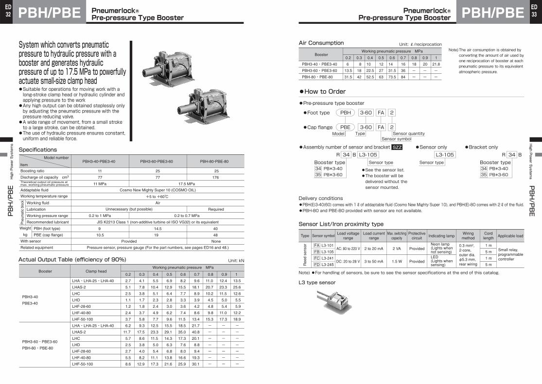
System which converts pneumatic pressure to hydraulic pressure with a booster and generates hydraulic pressure of up to 17.5 MPa to powerfully actuate small-size clamp head●Suitable for operations for moving work with a long-stroke clamp head or hydraulic cylinder and applying pressure to the work
●Any high output can be obtained steplessly only by adjusting the pneumatic pressure with the pressure reducing valve.
●A wide range of movement, from a small stroke to a large stroke, can be obtained.
●The use of hydraulic pressure ensures constant, uniform and reliable force.
Specifications
Actual Output Table (efficiency of 90%) Unit: kN
PBH3-40・PBE3-40
11
77
11 MPa
PBH3-60・PBE3-60 PBH-80・PBE-80
25
77
25
176
17.5 MPa
Cosmo New Mighty Super 10 (COSMO OIL)
+5 to +60℃ Air
Unnecessary (but possible) Required
0.2 to 0.7 MPa0.2 to 1 MPa
JIS K2213 Class 1 (non-additive turbine oil ISO VG32) or its equivalent
Pressure sensor, pressure gauge (For the part numbers, see pages ED16 and 48.)
PBH (foot type)
PBE (cap flange)
40
48
NoneProvided
9
10.5
14.5
19
PBH3-40
PBE3-40
PBH3-60・PBE3-60
PBH-80・PBE-80
LHA・LHA-25・LHA-40
LHAS-2
LHC
LHD
LHF-28-60
LHF-40-80
LHF-50-100
LHA・LHA-25・LHA-40
LHAS-2
LHC
LHD
LHF-28-60
LHF-40-80
LHF-50-100
0.2
2.7
5.1
2.5
1.1
1.2
2.4
3.7
6.2
11.7
5.7
2.5
2.7
5.5
8.6
0.3
4.1
7.8
3.8
1.7
1.8
3.7
5.8
9.3
17.5
8.6
3.8
4.0
8.2
12.9
0.4
5.5
10.4
5.1
2.3
2.4
4.9
7.7
12.5
23.3
11.5
5.0
5.4
11.1
17.3
0.5
6.9
12.9
6.4
2.8
3.0
6.2
9.6
15.5
29.1
14.3
6.3
6.8
13.8
21.6
0.6
8.2
15.5
7.7
3.3
3.6
7.4
11.5
18.5
35.0
17.3
7.6
8.0
16.6
25.9
0.7
9.6
18.1
8.9
3.9
4.2
8.6
13.4
21.7
40.8
20.1
8.8
9.4
19.3
30.1
0.8
11.0
20.7
10.2
4.5
4.8
9.8
15.3
-
-
-
-
-
-
-
0.9
12.4
23.3
11.5
5.0
5.4
11.0
17.3
-
-
-
-
-
-
-
1
13.5
25.6
12.6
5.5
5.9
12.2
18.9
-
-
-
-
-
-
-
Model number
Item
Boosting ratio
Discharge oil capacity cm3
Theoretical output oil pressure at max. working pneumatic pressure
Addaptable fluid
Working temperature range
Pneu
mat
ic b
lock Working fluid
Lubrication
Working pressure range
Recommended lubricant
Weight
kg
With sensor
Related equipment
Sensor symbolMax. switching
capacityLoad voltage
rangeLoad current
rangeCord
length Applicable loadType
Ree
d se
nsor
Protectivecircuit Indicating lamp
Wiringmethod
Air Consumption Unit: ℓ/reciprocationNote) The air consumption is obtained by
converting the amount of air used by one reciprocation of booster at each pneumatic pressure to its equivalent atmospheric pressure.
●How to Order
Sensor List/Iron proximity type
Note) ●For handling of sensors, be sure to see the sensor specifications at the end of this catalog.
●Pre-pressure type booster
Model
●Foot type PBH 3-60 FA 2
Type●Cap flange PBE 3-60 FA 2
R 34 B L3-105
34 PB*3-4035 PB*3-60
Booster type Sensor type
L3 type sensor
PBH3-40・PBE3-40
PBH3-60・PBE3-60
PBH-80・PBE-80
Working pneumatic pressure MPa
0.2
6
13.5
31.5
0.3
8
18
42
0.4
10
22.5
52.5
0.5
12
27
63
0.6
14
31.5
73.5
0.7
16
36
84
0.8
18
-
-
0.9
20
-
-
1
21.8
-
-
Booster
FA L3-101
FB L3-105
FC L3-241
FD L3-245
AC: 80 to 220 V
DC: 20 to 28 V
2 to 20 mA
3 to 50 mA
2 VA
1.5 W
Sensor symbolSensor quantity
●Sensor only L3-105
Sensor type
●Bracket onlyR 34 B
34 PB*3-4035 PB*3-60
Booster type
●Assembly number of sensor and bracket SZZ
●See the sensor list.●The booster will be delivered without the sensor mounted.
Delivery conditions●PBH(E)3-40(60) comes with 1 ℓ of addaptable fluid (Cosmo New Mighty Super 10), and PBH(E)-80 comes with 2 ℓ of the fluid.●PBH-80 and PBE-80 provided with sensor are not available.
Provided
Provided
Neon lamp(Lights whennot sensing)LED(Lights when sensing)
0.3 mm², 2-core, outer dia. φ5.3 mm, rear wiring
1 m
5 m
1 m
5 m
Small relay, programmable controller

PBH/PBEPBH/PBE
High Power Systems
Pneumerlock® Pre-pressure Type Booster34
EDPBH/PBE
High P
ower S
ystems PBH/PBE
Pneumerlock® Pre-pressure Type Booster 35
ED
Unit: mm Unit: mm
PBH3-40 PBH3-60
PBH-80
Dimensional Table
Sensor Mounting Dimension
●For the procedures for fitting the sensors, see “Sensor fitting procedures”.
A
384
387
498
B
198
198
256
C
160
160
199
D
170
250
280
E
150
220
250
F
9
11
14
G
165
215
265
H
95
120
145
J
70
95
120
PBH3-40
PBH3-60
PBH-80
Note) Never remove the *-marked set screw at the end of the indicator. (The indicator may jump out.)
14.5 14.514 14B C
AED
J
4-F (Slotted holes)
2-RC3/8 (Pneumatic pressure inlets)
RC1/2 (Hydraulic pressure outlet)
H
G
RC1/2
4.5
RC1/4 (With plug)
11 mm 11 mm
25 mm
Limit detecting sensor
Stroke detecting sensor Oil level drop detecting sensor
Piston backward movement detecting sensor
B24.5 24.520 20
CA
E
D
4-F (Slotted holes)
J
H
G
Set screw*
4.5
RC1/4 (With plug)
With indicator
RC3/4
RC1/2
2-RC1/2 (Pneumatic pressure inlets)
Arbitrary
(Hydraulic pressure outlet)
SymbolModel number
A
380
382
495
B
218
218
296
C
150
150
179
D
12
14
20
E
184
254
-
F
120
175
225
G
92
134
180
H
φ14
φ18
φ22
J
178
270
325
K
150
220
275
L
95
120
145
PBE3-40
PBE3-60
PBE-80
PBE3-40 PBE3-60
PBE-80
Sensor Mounting Dimension
●For the procedures for fitting the sensors, see “Sensor fitting procedures”.
Note) Never remove the *-marked set screw at the end of the indicator. (The indicator may jump out.)
RC1/4 (With plug)
L
E
BD C
A
RC1/2(Hydraulic pressure outlet)
RC1/2
4-H G
F
K J
2-RC3/8(Pneumatic pressure inlets)
(Mounting holes)
11 mm 11 mm
25 mm
Limit detecting sensor
Stroke detecting sensor Oil level drop detecting sensor
Piston backward movement detecting sensor
With indicator
L
BD C
A
RC3/4(Hydraulic pressure outlet)
RC1/2
4-H G
F
K J
2-RC1/2(Air inlets)
(Mounting holes)
Set screw*
Dimensional TableSymbol
Model number
Arbitrary
RC1/4 (With plug)
CAD/DATAis available.HIGHPOWER/THIGH C,D
CAD/DATAis available.HIGHPOWER/THIGH C,D
PBH/PBEPBH/PBE
High Power Systems
Pneumerlock® Pre-pressure Type Booster36
EDPBH/PBE
High P
ower S
ystems PBH/PBE
Pneumerlock® Pre-pressure Type Booster 37
ED
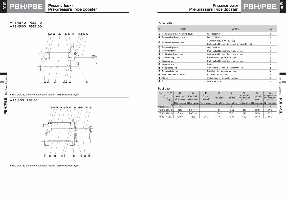
●PBH3-40・PBE3-40●PBH3-60・PBE3-60
●PBH-80・PBE-80
●This drawing shows the sectional view of PBH model (foot type).
●This drawing shows the sectional view of PBH model (foot type).
❹1617 ❸ 16
❷ 12 ❺ ❶2021 23
❷ 12 ❺ ❶ ❼2021 23 11
13 24 221514 ❻
❹1617 ❸❽ 16 13 24 2219 ❾ ❻
Nitrile rubber Nitrile rubber Nitrile rubber Nitrile rubber Nitrile rubber Nitrile rubber Nitrile rubber Nitrile rubber
Name
Model number
Cylindertube gasket
Pneumaticpiston seal
Glandgasket
Rod sealHydraulic
cylinder tubegasket
Hydraulicseal
Pre-pressurechamber joint
gasketMaterial
Qty.
❶❷
❸
❹❺❻❼❽❾1112131415
Pre-pressure chamber joint Aluminum alloy casting
1
1
1
1
1
1
1
1
1
4
4
1
1
1
Seal List
2
G95
G145
G190
PBH3-40・PBE3-40
PBH3-60・PBE3-60
PBH-80・PBE-80
16
1
DXP100
DXP150
P185
17
1
-
-
G55
19
1
P30
P30
P40
20
Rod seal
1
PS-30
PS-30
PS-40
21
1
S46
S46
G50
22
1
IDU-30
IDU-30
IDU-40
23
2
P15
P15
P15
24
Parts List
Name Material Qty.No.
Hydraulic cylinder mounting cover
Pneumatic cylinder cover
Pneumatic cylinder tube
Pneumatic piston
Hydraulic piston
Hydraulic cylinder tube
Hydraulic cap cover
Indicator rod
Indicator pipe
Hydraulic tie rod
Pneumatic tie rod
Grey cast iron
Grey cast iron
Aluminum alloy (PB*-40・60)Carbon steel for machine structural use (PB*-80)Grey cast iron
Carbon steel for machine structural use
Carbon steel for machine structural use
Rolled steel for general structure
Carbon steel for machine structural use
Resin
Chromium-molybdenum steel (PB*-80)
Rolled steel for general structure
Flange
Ring
Rolled steel for general structure
Hard steel wire
Pneumerlock®High Power Systems
38ED Oil-Air Converter for Pneumerlock®
Pre-pressure Type Booster AHU2High P
ower S
ystems AHU2
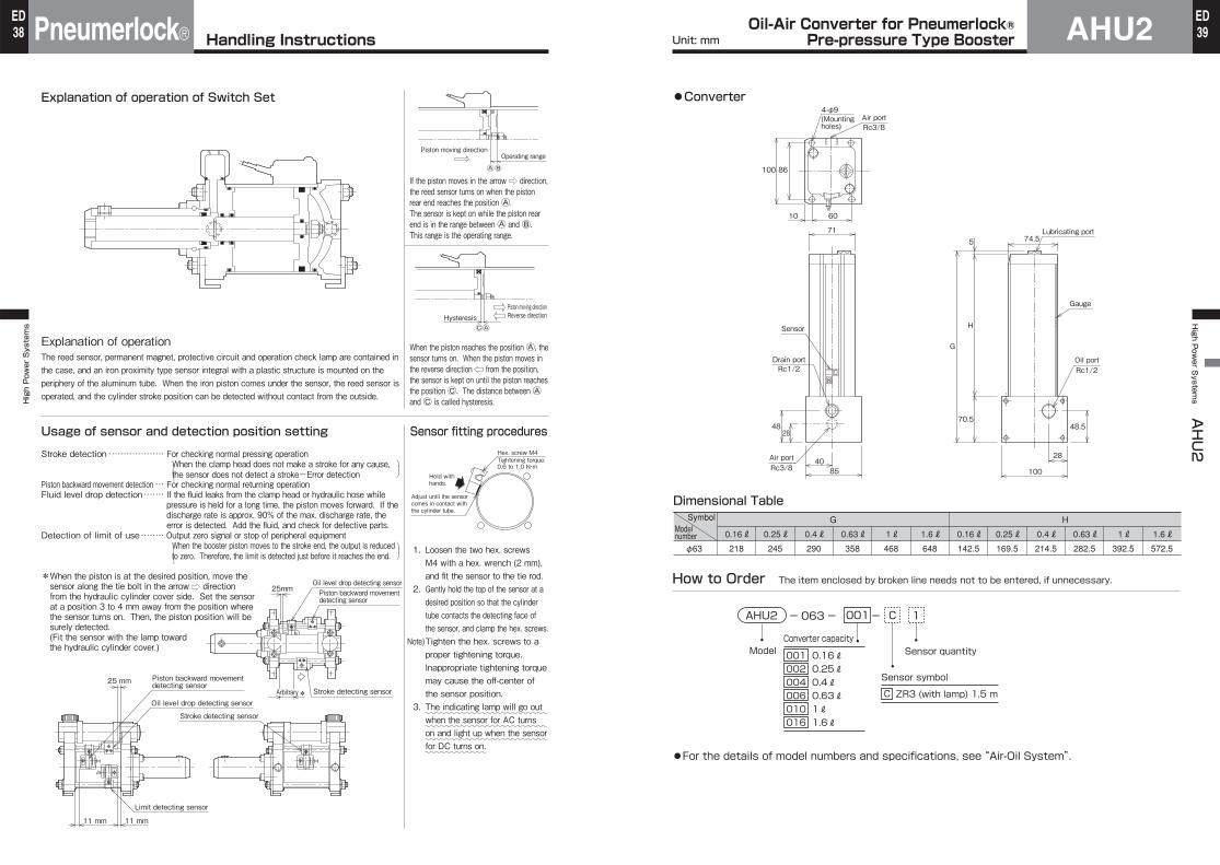
Explanation of operation of Switch Set
Usage of sensor and detection position setting
Explanation of operationThe reed sensor, permanent magnet, protective circuit and operation check lamp are contained in the case, and an iron proximity type sensor integral with a plastic structure is mounted on the periphery of the aluminum tube. When the iron piston comes under the sensor, the reed sensor is operated, and the cylinder stroke position can be detected without contact from the outside.
If the piston moves in the arrow direction, the reed sensor turns on when the piston rear end reaches the position Ⓐ. The sensor is kept on while the piston rear end is in the range between Ⓐ and Ⓑ. This range is the operating range.
When the piston reaches the position Ⓐ, the sensor turns on. When the piston moves in the reverse direction from the position, the sensor is kept on until the piston reaches the position Ⓒ. The distance between Ⓐ and Ⓒ is called hysteresis.
Stroke detection For checking normal pressing operationWhen the clamp head does not make a stroke for any cause, the sensor does not detect a stroke-Error detection
If the fluid leaks from the clamp head or hydraulic hose while pressure is held for a long time, the piston moves forward. If the discharge rate is approx. 90% of the max. discharge rate, the error is detected. Add the fluid, and check for defective parts.
Piston backward movement detectionFluid level drop detection
Detection of limit of useWhen the booster piston moves to the stroke end, the output is reduced to zero. Therefore, the limit is detected just before it reaches the end.
For checking normal returning operation
Output zero signal or stop of peripheral equipment
*When the piston is at the desired position, move the sensor along the tie bolt in the arrow direction from the hydraulic cylinder cover side. Set the sensor at a position 3 to 4 mm away from the position where the sensor turns on. Then, the piston position will be surely detected.(Fit the sensor with the lamp toward the hydraulic cylinder cover.)
1. Loosen the two hex. screws M4 with a hex. wrench (2 mm), and fit the sensor to the tie rod.
2. Gently hold the top of the sensor at a desired position so that the cylinder tube contacts the detecting face of the sensor, and clamp the hex. screws.
3. The indicating lamp will go out when the sensor for AC turns on and light up when the sensor for DC turns on.
Note)Tighten the hex. screws to a proper tightening torque. Inappropriate tightening torque may cause the off-center of the sensor position.
Sensor fitting procedures
~~~~~~~~~~~~~~~~~~~~~~~~
~~~~~~~~~~~~~~~~~~~~~~~~
~~~~~~~~~~~~~~~~~~~~~~~~
~~~~~~~~~~~~
Operating range
ⒶⒷ
Piston moving direction
HysteresisⒸⒶ
Piston moving directionReverse direction
11 mm 11 mm
25 mm
25mm
*
Limit detecting sensor
Stroke detecting sensor
Stroke detecting sensor
Oil level drop detecting sensor
Piston backward movement detecting sensor
Piston backward movement detecting sensor
Oil level drop detecting sensor
Hex. screw M4Tightening torque: 0.6 to 1.0 N・m
Hold with hands.
Adjust until the sensor comes in contact with the cylinder tube.
Arbitrary
・・・・・・・・・・・・・・・・・・・
・・・
・・・・・・・
・・・・・・・・
⎞⎟⎠
⎞⎟
⎠
⎞⎟⎠
⎞⎟
⎠
●Converter
How to Order The item enclosed by broken line needs not to be entered, if unnecessary.
●For the details of model numbers and specifications, see “Air-Oil System”.
Dimensional Table
0.16ℓ218
0.25ℓ245
0.4ℓ290
0.63ℓ358
1ℓ468
1.6ℓ648
0.16ℓ142.5
0.25ℓ169.5
0.4ℓ214.5
0.63ℓ282.5
1ℓ392.5
1.6ℓ572.5φ63
SymbolModel number
G H
Sensor quantityModel
ZR3 (with lamp) 1.5 m
CAHU2 1- - 063 - 001
Sensor symbol
C
0.16ℓ0.25ℓ0.4ℓ0.63ℓ1ℓ1.6ℓ
Converter capacity
001002004006010016
Rc1/2 Rc1/2
Rc3/840
4828
G
H
5
70.5
71
Drain port
Lubricating port
100
Sensor
85
28
48.5
Oil port
Air port
Rc3/8Air port
74.5
Gauge
(Mounting holes)
100 86
10 60
4-φ9
Unit: mmHandling Instructions 39ED
LH LHLH High Power Systems H
igh Power S
ystems LH
No. Qty.Name Material
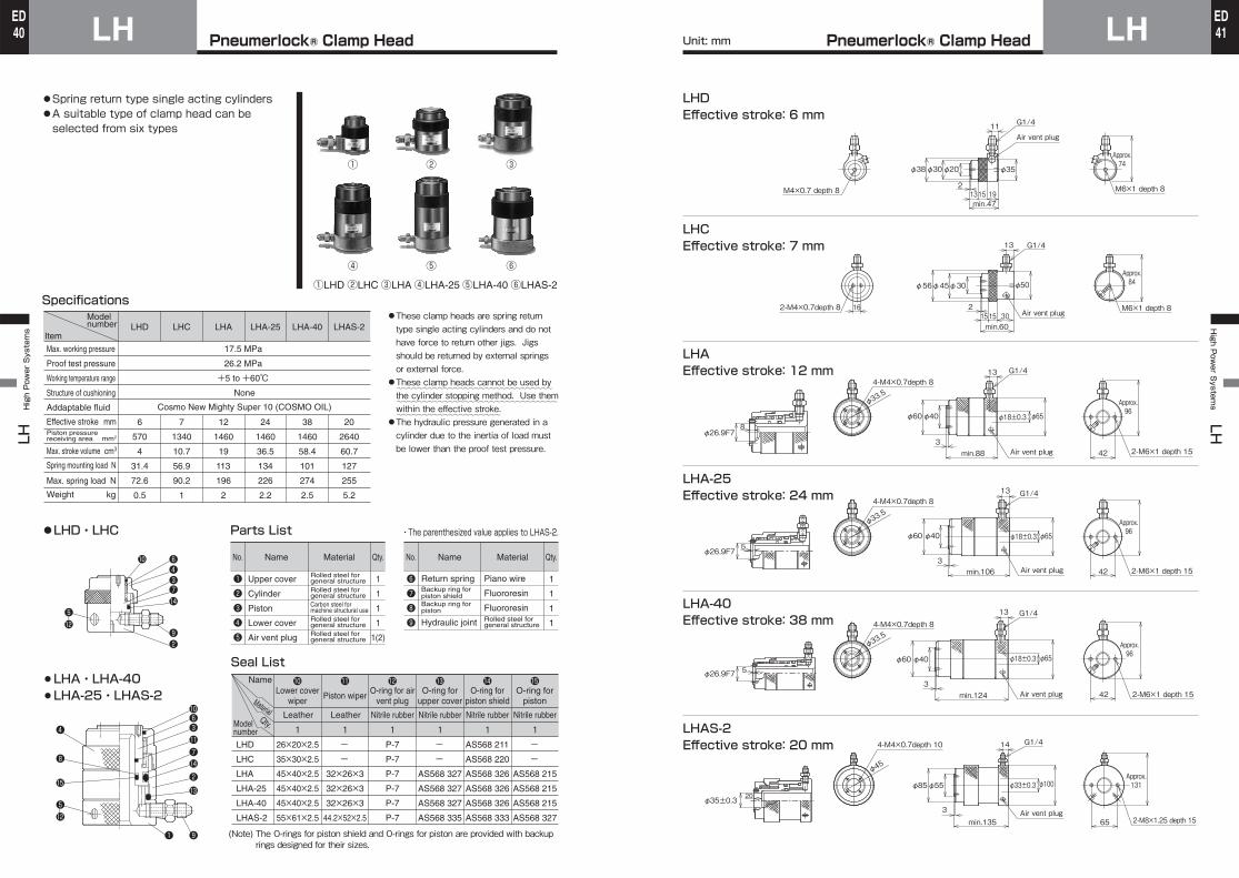
●Spring return type single acting cylinders●A suitable type of clamp head can be selected from six types
Specifications●These clamp heads are spring return type single acting cylinders and do not have force to return other jigs. Jigs should be returned by external springs or external force.●These clamp heads cannot be used by the cylinder stopping method. Use them within the effective stroke.●The hydraulic pressure generated in a cylinder due to the inertia of load must be lower than the proof test pressure.
Model number
Item
Max. working pressure
Proof test pressure
Working temperature range
Structure of cushioning
Addaptable fluid
Effective stroke mmPiston pressure receiving area
Max. stroke volume
Spring mounting load N
Max. spring load N
Weight
cm3
mm2
kg
LHD LHC LHA LHA-25 LHA-40 LHAS-2
17.5 MPa
26.2 MPa
+5 to +60℃ None
Cosmo New Mighty Super 10 (COSMO OIL)
6
570
4
31.4
72.6
0.5
7
1340
10.7
56.9
90.2
1
12
1460
19
113
196
2
24
1460
36.5
134
226
2.2
38
1460
58.4
101
274
2.5
20
2640
60.7
127
255
5.2
●LHD・LHC
¡LHA・LHA-40¡LHA-25・LHAS-2
No.
❶❷❸❹❺
Qty.
1
1
1
1
1(2)
Name Material
Upper cover
Cylinder
Piston
Lower cover
Air vent plug
Rolled steel for general structureRolled steel for general structureCarbon steel for machine structural useRolled steel for general structureRolled steel for general structure
❻❼❽❾
1
1
1
1
Return springBackup ring for piston shieldBackup ring for piston
Hydraulic joint
Piano wire
Fluororesin
FluororesinRolled steel for general structure
Parts List
Seal List
LHD
LHC
LHA
LHA-25
LHA-40
LHAS-2
Name
Model number
MaterialQty.
121110Lower cover
wiperPiston wiper
O-ring forpiston
O-ring forpiston shield
O-ring forupper cover
O-ring for airvent plug
13 14
Nitrile rubberNitrile rubberNitrile rubberNitrile rubber
1 -
-
AS568 215
AS568 215
AS568 215
AS568 327
1 AS568 211
AS568 220
AS568 326
AS568 326
AS568 326
AS568 333
1 -
-
AS568 327
AS568 327
AS568 327
AS568 335
1 P-7
P-7
P-7
P-7
P-7
P-7
Leather
1 -
-
32×26×3
32×26×3
32×26×3
44.2×52×2.5
Leather
1 26×20×2.5
35×30×2.5
45×40×2.5
45×40×2.5
45×40×2.5
55×61×2.5
15
①LHD②LHC③LHA④LHA-25⑤LHA-40⑥LHAS-2
~~~~~~~~~~~~~~~~~~~~~~~~~~~~~~
~~~~~~~~~~~~~~~~~~~~~~~~~~~~~~~
~~~~~~~~~~~~~~~~~~~~
・The parenthesized value applies to LHAS-2.
(Note) The O-rings for piston shield and O-rings for piston are provided with backup rings designed for their sizes.
❹❻
❸❼14
❷
❺12
10
❾
10❻❸11❼14
13
❾❶
❷
❺
15
❽
❹
12
① ② ③
④ ⑤ ⑥
LHDEffective stroke: 6 mm
LHCEffective stroke: 7 mm
LHAEffective stroke: 12 mm
LHA-25Effective stroke: 24 mm
LHA-40Effective stroke: 38 mm
LHAS-2Effective stroke: 20 mm
11
1315 19min.47
Air vent plug
M6×1 depth 8
G1/4
φ38φ30φ20 φ35
M4×0.7 depth 82
Approx.74
13
215 15 30min.60
16Air vent plug
G1/4
φ56φ45φ30 φ50
2-M4×0.7depth 8 M6×1 depth 8
Approx.84
13
423
min.88 Air vent plug
G1/4
φ18±0.3φ60φ40 φ65
2-M6×1 depth 15
Approx.96
φ33.54-M4×0.7depth 8
2-M6×1 depth 15
Approx.96
13
423
min.106 Air vent plug
φ18±0.3
G1/4
φ60φ40 φ65
φ33.54-M4×0.7depth 8
2-M6×1 depth 15
Approx.96
13
423
min.124 Air vent plug
G1/4
φ60φ40 φ18±0.3 φ65
φ33.54-M4×0.7depth 8
2-M8×1.25 depth 15
Approx.131
653
min.135Air vent plug
14 G1/4
φ85φ55 φ33±0.3 φ100
φ45
4-M4×0.7depth 10
8φ26.9F7
φ26.9F75
φ26.9F7 5
φ35±0.3 20
Unit: mmPneumerlock® Clamp Head Pneumerlock® Clamp Head 4140EDED
LHF
High Power Systems
LHF Pneumerlock® Clamp Head for Pre-Pressure Type Booster42
EDHigh P
ower S
ystems LHF
LHFPneumerlock® Clamp Head for Pre-Pressure Type Booster 43
ED
Clamp heads for pre-pressure type booster●Air return type hydraulic cylinders●A suitable clamp head for pre-pressure type booster can be selected from three types according to the purpose of use.
Specifications●To calculate the air consumption on the retraction side, multiply the max. stroke volume on retraction side shown above by (gauge pressure+1).●These clamp heads cannot be used by the cylinder stopping method. Use them within the maximum stroke.
Note) At the maximum stroke, the output is 0. The lower cover is not resistant to impact caused by collision. Therefore, it may be damaged.
●These clamp heads are designed specially for pre-pressure type boosters. They are a kind of air return hydraulic cylinders.To return the clamp head mounted with a jig, use a return spring or another mechanism.●The hydraulic pressure generated in a cylinder due to the inertia of load must be lower than the proof test pressure.
Model number
ItemProof test pressure on extension side
Working temperature range
Structure of cushioning
Addaptable fluid
Max. stroke
Max. working hydraulic pressure on extension side MPa Max. stroke oil capacity on extension sidePiston area onretraction sideMax. working pneumatic pressure on retraction side MPa Max. stroke volume on retraction side
Weight
Applicable brackets
kg
LHF-28-60 LHF-40-80 LHF-50-100
26.2 MPa
+5 to +60℃
None
Cosmo New Mighty Super 10 (COSMO OIL)
62
610
17.5
38
410
1
25.7
1.1
D3600
V3600
H3600
82
1250
17.5
103
540
1
45.1
2.3
D4800
V4800
H4800
103
1950
17.5
201
700
1
72.1
4.3
D6000
V6000
H6000
0 -1.5
0 -1.5
0 -2.0
①LHF-28-60②LHF-40-80③LHF-50-100
~~~~~~~~~~~~~~~~~~~~~~~~~~~~~
~~~~~~~~~~~~~~~~~~~~~~~~~~~~~~
~~~~~~~~~~~~~~~~~~~~
①
②
③
Piston area onextension side mm2
mm2
cm3
cm3
Name
Model number
MaterialQty.
Parts List
Seal List
¡LHF-28-60¡LHF-40-80¡LHF-50-100
No.
❶❷❸❹❺❻
Qty.Name Material Qty.Name Material
1
1
1
1
1
1
Upper cover
Tube
Lower cover
Rod
Bush
Piston
Carbon steel for machine structural use
Carbon steel for machine structural use
Carbon steel for machine structural use
Carbon steel for machine structural use
Oil-impregnated sintered bearing
Carbon steel for machine structural use
No.
❼❽❾101112
1
1
2
1
1
1
Rod end attachment
Positioning ring
Clamp ring
Disk
Air vent plug
Hydraulic joint
Carbon steel for machine structural use
Carbon steel for machine structural use
Carbon steel for machine structural use
Sintered metal
Rolled steel for general structure
Rolled steel for general structure
1
S-30
S-42
S-53
LHF-28-60
LHF-40-80
LHF-50-100
13
1
DRP-16
DRP-30
DRP-40
14
1
DOL-20
DOL-30
DOL-40
15
1
28×2.5×2
SWA-40
SWA-50
16
1
ODU-28
ODU-40
ODU-50
17
1
P-7
P-7
P-7
18
❷ ❶15❻ 17 1213❽ 16
11, 18
❼ ❸ ❺ ❾ ❹1014
Nitrile rubber
Tube gasket
Nitrile rubber
Rod seal
Nitrile rubber
Piston seal(on pneumatic side)
Synthetic resin
Wear ring
Nitrile rubber
Piston seal(on hydraulic side)
Nitrile rubber
O-ring forair vent plug
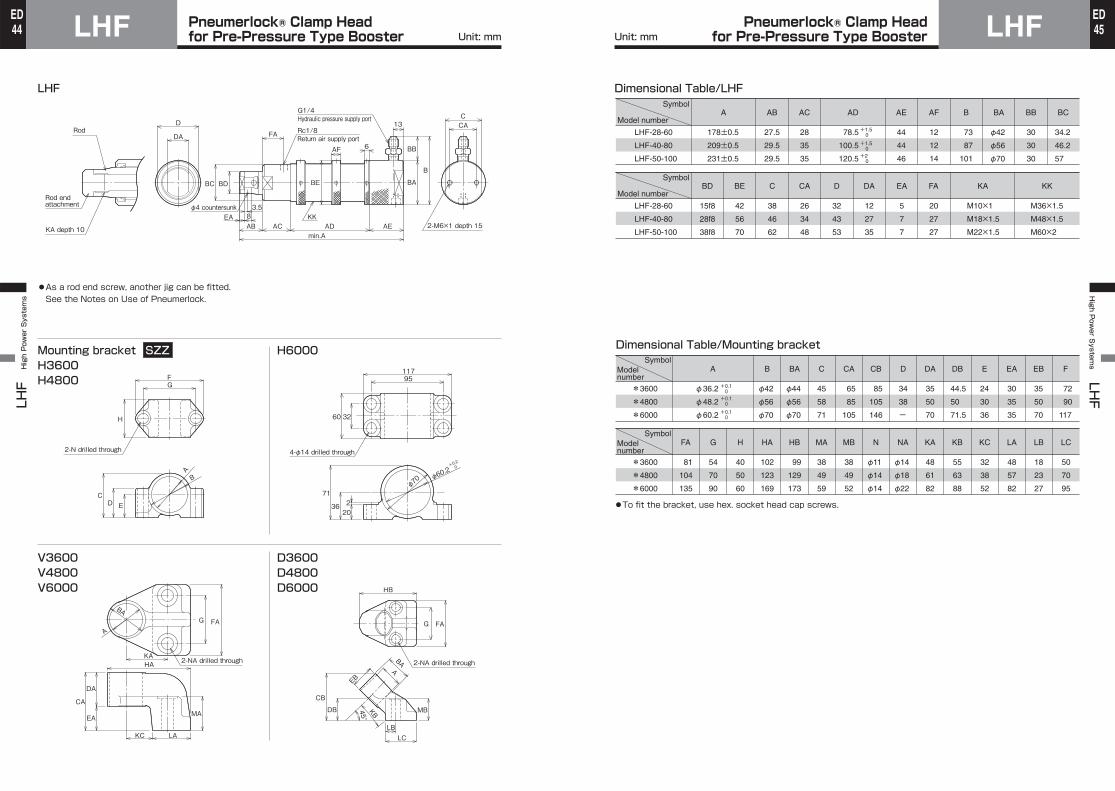
LHF
High Power Systems
LHF Pneumerlock® Clamp Head for Pre-Pressure Type Booster44
EDHigh P
ower S
ystems LHF
LHFPneumerlock® Clamp Head for Pre-Pressure Type Booster 45
ED
LHF
●As a rod end screw, another jig can be fitted.See the Notes on Use of Pneumerlock.
Mounting bracket SZZH3600H4800
H6000
V3600V4800V6000
D3600D4800D6000
Return air supply port
Hydraulic pressure supply port
2-M6×1 depth 15
G1/4
EA 8AB AC AD AE
min.A
3.5
FA
AF
KK
6
13
B
BB
BABDBC BE
Rc1/8
φ4 countersunk
RodD
DA
CAC
Rod end attachment
KA depth 10
FG
H
CD E
B
A
2-N drilled through
11795
60 32
71
36202
4-φ14 drilled through
φ70 φ60
.2+0.2
0
KAHA
KC LA
FAG
MA
CA
DA
EA
2-NA drilled through
A
BA
EB
BAA
KB
HB
FAG
MB
LCLB
CB
DB 45°
2-NA drilled through
A
178±0.5
209±0.5
231±0.5
AB
27.5
29.5
29.5
AC
28
35
35
LHF-28-60
LHF-40-80
LHF-50-100
Symbol
Model number
Symbol
Model number
AD
78.5
100.5
120.5
AE
44
44
46
AF
12
12
14
B
73
87
101
BA
φ42
φ56
φ70
BB
30
30
30
+1.5 0
+1.5 0+2 0
BC
34.2
46.2
57
BD
15f8
28f8
38f8
BE
42
56
70
C
38
46
62
CA
26
34
48
D
32
43
53
DA
12
27
35
EA
5
7
7
FA
20
27
27
KA
M10×1
M18×1.5
M22×1.5
KK
M36×1.5
M48×1.5
M60×2
LHF-28-60
LHF-40-80
LHF-50-100
Dimensional Table/LHF
Dimensional Table/Mounting bracket
*3600
*4800
*6000
SymbolModelnumber
SymbolModelnumber
*3600
*4800
*6000
A
φ36.2
φ48.2
φ60.2
B
φ42
φ56
φ70
BA
φ44
φ56
φ70
C
45
58
71
CA
65
85
105
CB
85
105
146
D
34
38
-
DA
35
50
70
DB
44.5
50
71.5
E
24
30
36
EA
30
35
35
EB
35
50
70
+0.1 0+0.1 0
+0.1 0
F
72
90
117
FA
81
104
135
G
54
70
90
H
40
50
60
HA
102
123
169
HB
99
129
173
MA
38
49
59
MB
38
49
52
N
φ11
φ14
φ14
NA
φ14
φ18
φ22
KA
48
61
82
KB
55
63
88
KC
32
38
52
LA
48
57
82
LB
18
23
27
LC
50
70
95
●To fit the bracket, use hex. socket head cap screws.
Unit: mm Unit: mm
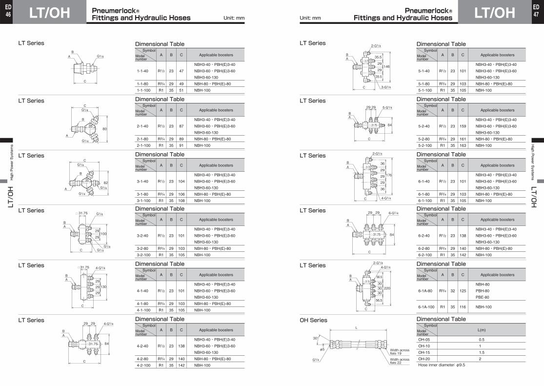
Pneumerlock® Fittings and Hydraulic HosesLT/OH Pneumerlock®
Fittings and Hydraulic Hoses LT/OHLT/OH High Power Systems H
igh Power S
ystems LT/O
H
LT Series
LT Series
LT Series
LT Series
LT Series
LT Series
B
23
29
35
C
87
89
91
2-1-40
2-1-80
2-1-100
NBH3-40・PBH(E)3-40
NBH3-60・PBH(E)3-60
NBH3-60-130
NBH-80・PBH(E)-80
NBH-100
A
R1/2
R3/4
R1
A
R1/2
R3/4
R1
B
23
29
35
C
47
49
51
Applicable boosters
1-1-40
1-1-80
1-1-100
SymbolModelnumber
Applicable boostersSymbol
Modelnumber
NBH3-40・PBH(E)3-40
NBH3-60・PBH(E)3-60
NBH3-60-130
NBH-80・PBH(E)-80
NBH-100
Dimensional Table
Dimensional Table
Dimensional Table
B
23
29
35
C
104
106
108
3-1-40
3-1-80
3-1-100
NBH3-40・PBH(E)3-40
NBH3-60・PBH(E)3-60
NBH3-60-130
NBH-80・PBH(E)-80
NBH-100
A
R1/2
R3/4
R1
Dimensional Table
Dimensional Table
Dimensional Table
B
23
29
35
C
101
103
105
3-2-40
3-2-80
3-2-100
NBH3-40・PBH(E)3-40
NBH3-60・PBH(E)3-60
NBH3-60-130
NBH-80・PBH(E)-80
NBH-100
A
R1/2
R3/4
R1
B
23
29
35
C
101
103
105
4-1-40
4-1-80
4-1-100
NBH3-40・PBH(E)3-40
NBH3-60・PBH(E)3-60
NBH3-60-130
NBH-80・PBH(E)-80
NBH-100
A
R1/2
R3/4
R1
B
23
29
35
C
138
140
142
4-2-40
4-2-80
4-2-100
NBH3-40・PBH(E)3-40
NBH3-60・PBH(E)3-60
NBH3-60-130
NBH-80・PBH(E)-80
NBH-100
A
R1/2
R3/4
R1
BA
C
G1/4
C
B
A
8035
C
B
A
8235
C
□ 31.75
29100
29
AB
C
AB
□ 31.75
29
13029
29
4-G1/4
C
AB
29 29
84□ 31.75
4-G1/4
Applicable boostersSymbol
Modelnumber
Applicable boostersSymbol
Modelnumber
Applicable boostersSymbol
Modelnumber
Applicable boostersSymbol
Modelnumber
G1/4
G1/4
G1/4
G1/4
G1/4
G1/4
G1/4G1/4
LT Series
LT Series
LT Series
LT Series
LT Series
OH Series
Dimensional Table
Dimensional Table
Dimensional Table
Dimensional Table
Dimensional Table
Dimensional Table
B
23
29
35
C
101
103
105
5-1-40
5-1-80
5-1-100
NBH3-40・PBH(E)3-40
NBH3-60・PBH(E)3-60
NBH3-60-130
NBH-80・PBH(E)-80
NBH-100
A
R1/2
R3/4
R1
B
23
29
35
C
159
161
163
5-2-40
5-2-80
5-2-100
NBH3-40・PBH(E)3-40
NBH3-60・PBH(E)3-60
NBH3-60-130
NBH-80・PBH(E)-80
NBH-100
A
R1/2
R3/4
R1
B
23
29
35
C
101
103
105
6-1-40
6-1-80
6-1-100
NBH3-40・PBH(E)3-40
NBH3-60・PBH(E)3-60
NBH3-60-130
NBH-80・PBH(E)-80
NBH-100
A
R1/2
R3/4
R1
B
23
29
35
C
138
140
142
6-2-40
6-2-80
6-2-100
NBH3-40・PBH(E)3-40
NBH3-60・PBH(E)3-60
NBH3-60-130
NBH-80・PBH(E)-80
NBH-100
A
R1/2
R3/4
R1
B
32
35
C
125
116
6-1A-80
6-1A-100
NBH-80
PBH-80
PBE-80
NBH-100
A
R3/4
R1
L(m)
0.5
1
1.5
2
OH-05
OH-10
OH-15
OH-20
Hose inner diameter: φ9.5
C
29146
29
AB
35.5
35.5□ 31.75
2-G1/4
3-G1/4
C
AB
29 29
84□ 31.75
5-G1/4
2917629
29
A
C
B
36
36□ 31.75
2-G1/4
4-G1/4
C
AB
29 29
84□ 31.75
6-G1/4
303030
220
A
C
B 56.5
56.5
□ 31.75
2-G1/44-G1/4
L
Width across flats 22
Width across flats 19
30°
G1/4
φ5
Applicable boostersSymbol
Modelnumber
Applicable boostersSymbol
Modelnumber
Applicable boostersSymbol
Modelnumber
Applicable boostersSymbol
Modelnumber
Applicable boostersSymbol
Modelnumber
SymbolModelnumber
Unit: mm Unit: mm 4746EDED

Pneumerlock®High Power Systems
48ED
Pneumerlock®High P
ower S
ystems
49ED
Specifications (for high pressure)Pressure Sensor
Pressure Gauge SZZ
Port size
Working fluid
Set pressure range
Proof test pressureDifference between opening pressure and closing pressureWorking temperature range
Protection structure
Accessories
Weight
0882100 0882200 0882300 0882400
G1/4
Hydraulic fluid or non-corrosive liquid
0.5 to 7 MPa 1 to 16 MPa 2.5 to 25 MPa 4 to 40 MPa
40 MPa
0.8 to 2 MPa 1.2 to 3.5 MPa 1.5 to 4 MPa 1.8 to 4.5 MPa
-10 to +70℃ (No freezing)
Dust-proof and drip-proof structure
Socket with neon lamp, reducing nipple
0.2 kg
60 MPa
Dimensional Table
A
76
76
77
77
B
6
6
7
7
C
21
21
22
22
0882100
0882200
0882300
0882400
SymbolModelnumber
Specifications
・Without glycerine ・Containing glycerine
Port size
R1/4
R1/4
R1/4
R1/4
Remarks
For 15 MPa
For 25 MPa
For 15 MPa (containing glycerine)
For 25 MPa (containing glycerine)
PG150Q-2
PG250Q-2
PG150Q-2G
PG250Q-2G
Model number
Wiring port
20
G 1 4/
Pressure adjustment part
Locking screw
φ5.2 (Mounting hole)
30
C15
30
35
70
B
A
75
(Width across flats)
Socket with neon lamp (semi-standard)27
R1/4
Unit: mm
φ63
24 ・The parenthesized value is the dimension of the pressure gauge containing glycerine.
10
30
(36)
Unit: mm
Item
Modelnumber
Conversion of pneumatic pressure to hydraulic pressure●Direct pressure type and pre-pressure type are available.●Boosters with sensors are available. (Optional)●Sensors can be fitted later.●Non-lubrication type
Iron Proximity Sensor Specifications
24 V DC
DC: 20 to 28 V
3 to 50 mA
1.5 W
0 mA
L3-241
L3-245
L3-101
L3-105
Small relay, programmable controller
Model number
●For handling of sensors, be sure to see the sensor specifications at the end of this catalog.
Boosting ratio
Discharge oil capacity(cm3)
Note)Frequency of operation
Hydraulic fluid to be used
Working temperature range
Working fluid
Lubrication
Working pressure range
Recommended lubricant
Weight (kg)With reed sensor
Related equipment
Main Body Specifications
35HBN63-30
Theoretical output oil pressure at max. working pneumatic pressure
35HBN63-50 35HBP63-30 35HBP63-50
30 50 30 50
Direct pressure type Pre-pressure type
7.8
4.7 MPa
6 times/min or less(Booster stroke time: each way for 5 sec or more, reciprocation for 10 sec or more)
+5 to +60℃Air
Unnecessary (but possible)
0.2 to 0.6 MPa
JIS K2213 Class (non-additive turbine oil ISO VG32) or its equivalent
2.9 3.2 2.3 2.6
Provided
Pressure sensor, pressure gauge
Item
Pneu
mat
ic b
lock
TypeModel number
Note) In the case of direct-pressure type, check carefully the return speed and the amount of returned fluid. If the return speed is high, the fluid may suddenly sucked into the reservoir tank, and the fluid may leak from the lubricating plug, or air bubbles may be mixed in the fluid.
Cosmo New Mighty Super 10 (COSMO OIL) or its equivalent
How to Order When placing an order, specify the model number shown below.
35HB N 63 ー 30 FA 2
Type❷Bore❸
Model❶
Discharg
e oil ca
pacity❹
Sensor quantity❻
Bore
Direct pressure typePre-pressure type
305030 cm350 cm3
Sensor quantity
Delivery conditions●The boosters will be delivered without sensors or mounting accessories mounted.●The boosters will come with 1 ℓ of addaptable fluid.
R 33 B L3-101
Assembly number of sensor and bracket●When placing an order for sensors only, specify the assembly number of sensor and bracket.
How to order pressure gauge
PG511Q-0
Bracket symbol Sensor type
Rated voltage
Load voltage range
Load current range
Max. switching capacity
Leakage current
Operating time
Return time
Impact resistance
Indicating lamp
Applicable load
With 1 m cord
With 5 m cord
1.2 ms or less
1 ms or less
196 m/s2 (unrepeated)
LED (Lights when sensing) Neon lamp (Lights when not sensing)
100/200 V AC
AC: 80 to 220 V
2 to 20 mA
2 VA
1 mA
L3 type sensor
FA L3-101FB L3-105FC L3-241FD L3-245
●Number of mountable sensors35HBN-63-30: Up to 1 pc. on one surface (up to 2 pcs. in all on right and left surfaces as viewed from front)35HBP-63-30: Up to 1 pc. on one surface (up to 3 pcs. in all on right, left and upper surfaces as viewed from front)35HBN-63-50: Up to 2 pcs. on one surface35HBP-63-50: Up to 2 pcs. on one surface
●In an environment with severe vibration, the sensors may be dislocated. In such an environment, it is recommended to use the tri-band type. (Order made)
●For details, see “Just Power System” in the general catalog of hydraulic equipment.
NP
Sensor symb
ol❺
Related Equipment/Pressure Sensors and Pressure Gauges Accessories/Air-Oil Booster 35HB
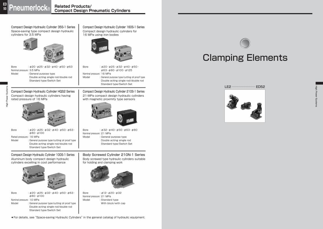
Pneumerlock®High Power Systems
50ED
High P
ower S
ystems
Compact Design Hydraulic Cylinder 35S-1 SeriesSpace-saving type compact design hydraulic cylinders for 3.5 MPa
¡For details, see “Space-saving Hydraulic Cylinders” in the general catalog of hydraulic equipment.
Bore : φ20・φ25・φ32・φ40・φ50・φ63Nominal pressure : 3.5 MPaModel : General purpose type
Double acting single rod/double rodStandard type/Switch Set
Compact Design Hydraulic Cylinder HQS2 Series
Bore : φ20・φ25・φ32・φ40・φ50・φ63・φ80・φ100
Rated pressure : 16 MPaModel : General purpose type/cutting oil proof type
Double acting single rod/double rodStandard type/Switch Set
Compact Design Hydraulic Cylinder 100S-1 Series
Bore : φ20・φ25・φ32・φ40・φ50・φ63・φ80・φ100
Nominal pressure : 10 MPaModel : General purpose type/cutting oil proof type
Double acting single rod/double rodStandard type/Switch Set
Compact Design Hydraulic Cylinder 160S-1 SeriesCompact design hydraulic cylinders for 16 MPa using iron bodies
Bore : φ20・φ25・φ32・φ40・φ50・φ63・φ80・φ100・φ125
Nominal pressure : 16 MPaModel : General purpose type/cutting oil proof type
Double acting single rod/double rodStandard type/Switch Set
Compact Design Hydraulic Cylinder 210S-1 Series21-MPa compact design hydraulic cylinders with magnetic proximity type sensors
Bore : φ32・φ40・φ50・φ63・φ80Nominal pressure : 21 MPaModel : General purpose type
Double acting single rodStandard type/Switch Set
Body Screwed Cylinder 210N-1 SeriesBody screwed type hydraulic cylinders suitable for holding and clamping work
Bore : φ12・φ20・φ32Nominal pressure : 21 MPaModel : Standard type
With block/with cap
Compact design hydraulic cylinders having rated pressure of 16 MPa
Aluminum body compact design hydraulic cylinders excelling in cost performance
Related Products/Compact Design Pneumatic Cylinders
Clamping Elements
LE2 ………………………… ED52
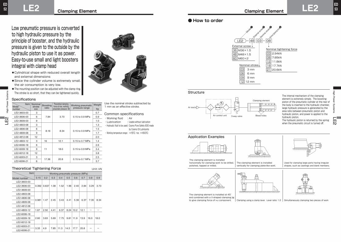
Clamping ElementLE2LE2 High Power Systems
52ED
Clamping Element LE2High P
ower S
ystems LE2
53ED
Low pneumatic pressure is converted to high hydraulic pressure by the principle of booster, and the hydraulic pressure is given to the outside by the hydraulic piston to use it as power.Easy-to-use small and light boosters integral with clamp head●Cylindrical shape with reduced overall length and external dimensions
●Since the cylinder volume is extremely small, the air consumption is very low.
●The mounting position can be adjusted with the clamp ring. The stroke is so short, that they can be tightened quickly.
SpecificationsUse the nominal stroke subtracted by 1 mm as an effective stroke.
Common specifications・Working fluid : Air ・Lubrication : Usable without lubrication・Hydraulic fluid to be used : Cosmo Pure Safety 830 made
by Cosmo Oil Lubricants ・Working temperature range : +5℃ to +60℃
LE2-3603-03
LE2-3606-03
LE2-3609-03
LE2-4803-08
LE2-4806-08
LE2-4809-08
LE2-4812-08
LE2-4803-12
LE2-6006-18
LE2-6009-18
LE2-6012-18
LE2-6003-21
LE2-6006-21
ItemModel number
Nominalstroke
mm
Boostingratio
Theoretical clamping force at max. working
pneumatic pressure kNWorking pneumatic
pressure rangeWeight
kg
3
6
9
3
6
9
12
3
6
9
12
3
6
7.84
8.16
16
11
17.36
3.73
8.34
12.1
18.0
20.8
0.15 to 0.9 MPa
0.15 to 0.9 MPa
0.15 to 0.7 MPa
0.15 to 0.9 MPa
0.15 to 0.7 MPa
0.7
0.9
1.0
1.3
1.5
1.7
2.0
1.4
2.6
3.4
3.8
2.5
3.7
Theoretical Tightening Force
LE2-3603-03
LE2-3606-03
LE2-3609-03
LE2-4803-08
LE2-4806-08
LE2-4809-08
LE2-4812-08
LE2-4803-12
LE2-6006-18
LE2-6009-18
LE2-6012-18
LE2-6003-21
LE2-6006-21
Item
Model number
Working pneumatic pressure (MPa)
0.392
0.981
1.67
2.60
3.33
0.637
1.47
2.50
3.63
4.9
1.08
2.45
4.41
5.69
7.85
1.52
3.43
6.37
7.75
11.3
1.96
4.41
8.24
9.81
14.5
2.40
5.39
10.2
11.9
17.7
2.84
6.37
12.1
13.9
20.8
3.29
7.35
ー
16.0
ー
3.73
8.34
ー
18.0
ー
0.15 0.2 0.3 0.4 0.5 0.6 0.7 0.8 0.9
Unit: kN
Structure
Application Examples
The internal mechanism of the clamping element is extremely simple. The boosting piston of the pneumatic cylinder at the rear of the body is inserted to the hydraulic chamber, large hydraulic pressure is generated by the area ratio between pneumatic piston and hydraulic piston, and power is applied to the hydraulic piston.The hydraulic piston is returned by the spring when the pneumatic circuit is turned off.
The clamping element is installed horizontally for clamping work to be drilled, polished, tapped or milled.
The clamping element is installed at 45° and combined with a V-shaped clamping jig to give clamping force of x-y component. Clamping using a clamp lever. Lever ratio: 1:2
The clamping element is installed vertically for clamping plate-like work.
Simultaneously clamping two pieces of work
Used for clamping large parts having irregular shapes, such as castings and blank members.
LE2 48 03 - 08-
Model❶
Exter
nal scre
w❷No
minal stro
ke❸
Nominal
tighteni
ng force❹
External screw
M36×1.5 M48×1.5 M60×2
36 48 60
Nominal tightening force
2.94kN 7.85kN 11.8kN 17.7kN 20.6kN
03 08 12 18 21
Nominal stroke
3 mm 6 mm 9 mm 12 mm
03 06 09 12
Air control unit
Air source
3-way valve
Clamping element
Bleed holes
●How to order
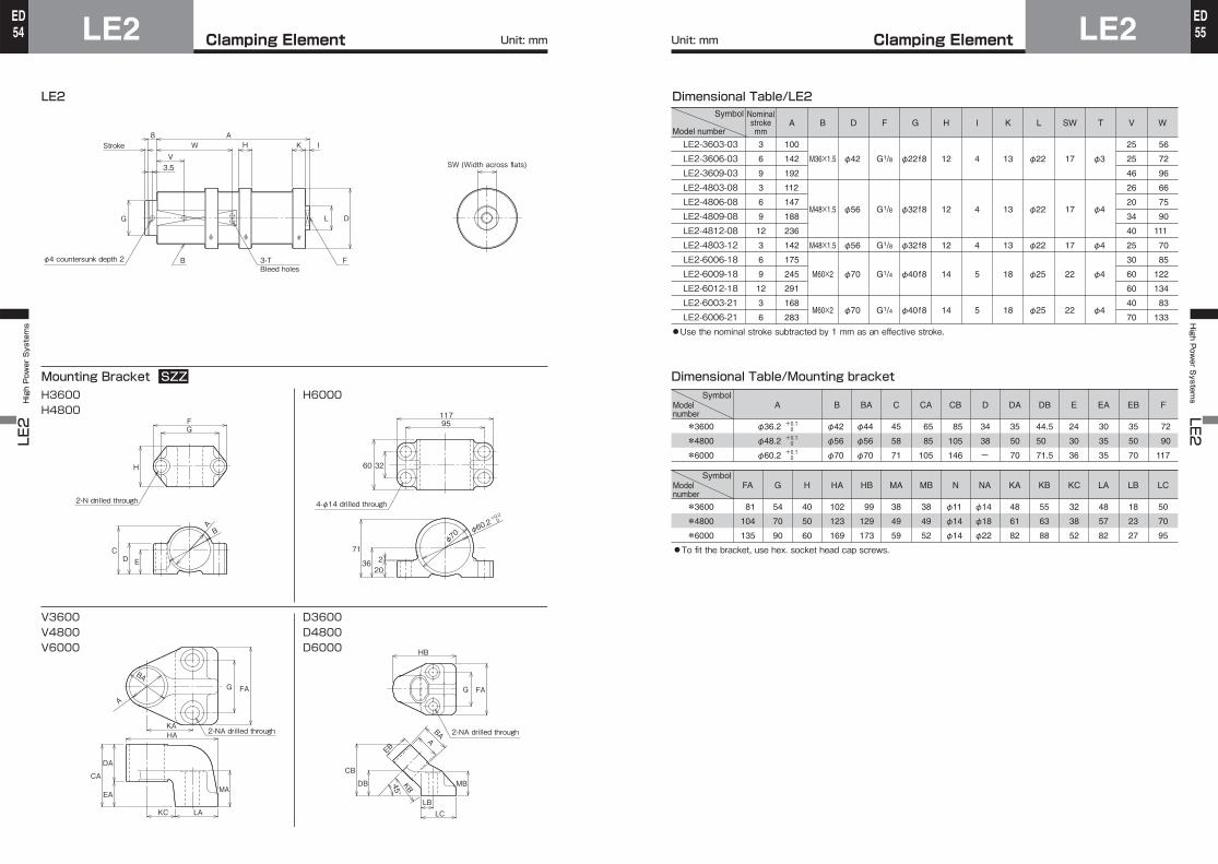
Clamping ElementLE2LE2 High Power Systems
54ED
Clamping Element LE2High P
ower S
ystems LE2
55ED
Unit: mm Unit: mm
LE2
Mounting Bracket SZZH3600H4800
H6000
V3600V4800V6000
D3600D4800D6000
G DL
8Stroke W H
AK I
V3.5 SW (Width across flats)
B 3-T Bleed holes
Fφ4 countersunk depth 2
FG
H
CD E
B
A
2-N drilled through
11795
60 32
71
36202
4-φ14 drilled through
φ70 φ60
.2+0.2
0
KAHA
KC LA
FAG
MA
CA
DA
EA
2-NA drilled through
A
BA
EB
BAA
KB
HB
FAG
MB
LCLB
CB
DB 45°
2-NA drilled through
Dimensional Table/LE2
Dimensional Table/Mounting bracket
Model number
Symbol
LE2-3603-03 LE2-3606-03 LE2-3609-03 LE2-4803-08 LE2-4806-08 LE2-4809-08 LE2-4812-08 LE2-4803-12 LE2-6006-18 LE2-6009-18 LE2-6012-18 LE2-6003-21 LE2-6006-21
Nominalstrokemm
3
6
9
3
6
9
12
3
6
9
12
3
6
A
100
142
192
112
147
188
236
142
175
245
291
168
283
B
M36×1.5
M48×1.5
M48×1.5
M60×2
M60×2
D
φ42
φ56
φ56
φ70
φ70
F
G1/8
G1/8
G1/8
G1/4
G1/4
G
φ22f8
φ32f8
φ32f8
φ40f8
φ40f8
H
12
12
12
14
14
I
4
4
4
5
5
K
13
13
13
18
18
L
φ22
φ22
φ22
φ25
φ25
SW
17
17
17
22
22
T
φ3
φ4
φ4
φ4
φ4
V
25
25
46
26
20
34
40
25
30
60
60
40
70
W
56
72
96
66
75
90
111
70
85
122
134
83
133
●Use the nominal stroke subtracted by 1 mm as an effective stroke.
Model number
Symbol
*3600
*4800
*6000
*3600
*4800
*6000
A
φ36.2
φ48.2
φ60.2
B
φ42
φ56
φ70
BA
φ44
φ56
φ70
C
45
58
71
CA
65
85
105
CB
85
105
146
D
34
38
-
DA
35
50
70
DB
44.5
50
71.5
E
24
30
36
EA
30
35
35
+0.1 0
+0.1 0
+0.1 0
EB
35
50
70
F
72
90
117
FA
81
104
135
G
54
70
90
H
40
50
60
HA
102
123
169
HB
99
129
173
MA
38
49
59
MB
38
49
52
N
φ11
φ14
φ14
NA
φ14
φ18
φ22
KA
48
61
82
KB
55
63
88
KC
32
38
52
LA
48
57
82
LB
18
23
27
LC
50
70
95
●To fit the bracket, use hex. socket head cap screws.
Model number
Symbol
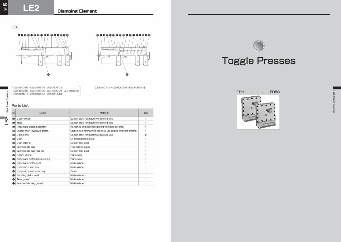
Clamping ElementLE2LE2 High Power Systems
56ED
High P
ower S
ystems
No.
❶❷❸❹❺❻❼❽❾1011121314151617
Name
Upper cover
Tube
Pneumatic piston assembly
Output shaft (hydraulic piston)
Clamp ring
Bush
Bush retainer
Intermediate ring
Intermediate ring retainer
Return spring
Pneumatic piston return spring
Pneumatic piston seal
Hydraulic piston seal
Hydraulic piston wear ring
Boosting piston seal
Tube gasket
Intermediate ring gasket
Material
Carbon steel for machine structural use
Carbon steel for machine structural use
Hardened and polished (plated with hard chrome)
Carbon steel for machine structural use (plated with hard chrome)
Carbon steel for machine structural use
Oil-impregnated metal
Carbon tool steel
Free cutting brass
Carbon tool steel
Piano wire
Piano wire
Nitrile rubber
Nitrile rubber
Resin
Nitrile rubber
Nitrile rubber
Nitrile rubber
Qty.
1
1
1
1
2
1
1
1
1
1
1
1
1
1
1
1
1
Parts List
[LE2-4803-12・LE2-6003-21・LE2-6006-21]LE2-3603-03・LE2-3606-03・LE2-3609-03LE2-4803-08・LE2-4806-08・LE2-4809-08・LE2-4812-08LE2-6006-18・LE2-6009-18・LE2-6012-18
❹ ❼ ❻ ❺ ❽ ❾ ❷ ❺❸1014 13 17 12❶16 ❹ ❼ ❻ ❺ ❽ ❾ ❷ ❺❸101413 17 1211 ❶16
LE2
15 15
TPH... ...........................ED58
Toggle Presses
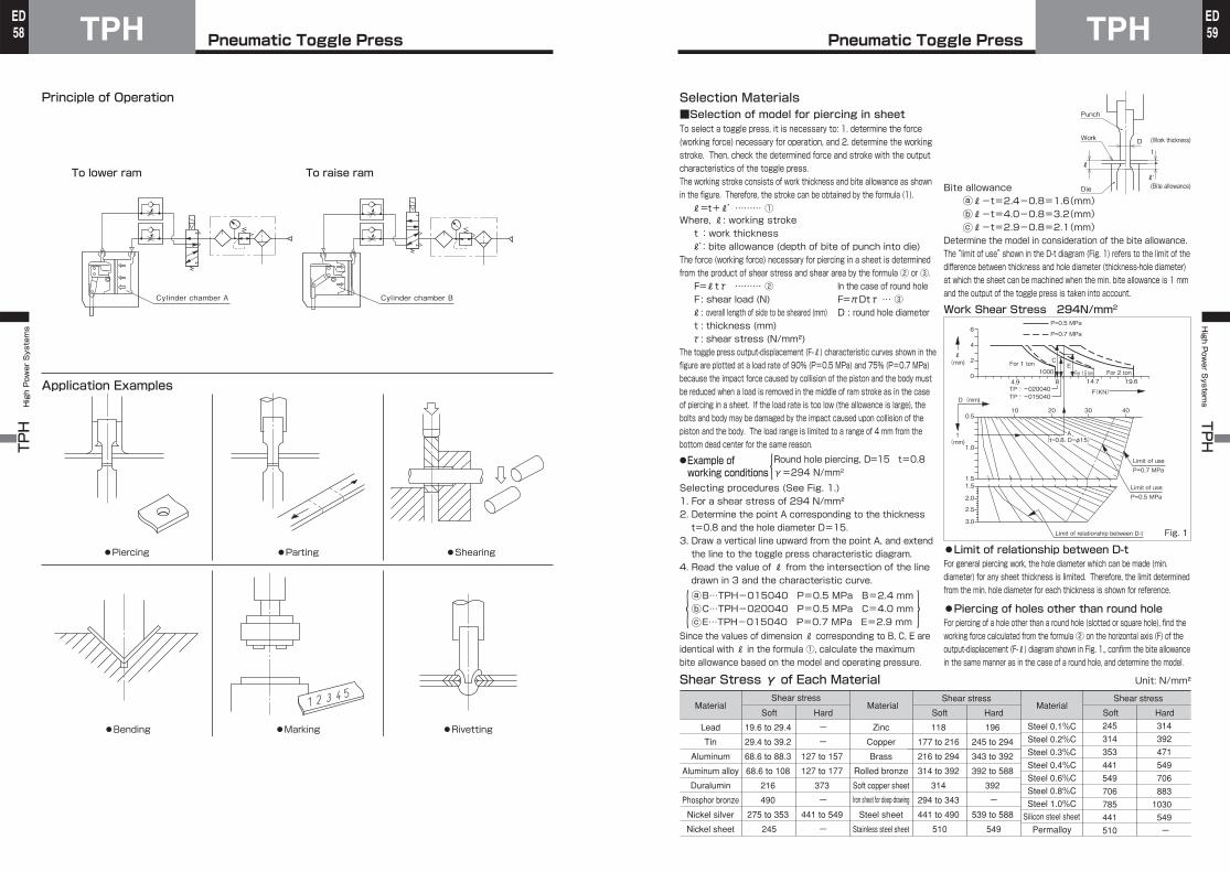
Pneumatic Toggle PressTPHTPH High Power Systems
58ED
Pneumatic Toggle Press TPHHigh P
ower S
ystems TPH
59ED
Principle of Operation
Application Examples
To lower ram To raise ram
●Piercing
●Bending
●Parting
●Marking
●Shearing
●Rivetting
Cylinder chamber A Cylinder chamber B
Bite allowanceℓ-t=2.4-0.8=1.6(mm)ℓ-t=4.0-0.8=3.2(mm)ℓ-t=2.9-0.8=2.1(mm)
Determine the model in consideration of the bite allowance.The “limit of use” shown in the D-t diagram (Fig. 1) refers to the limit of the difference between thickness and hole diameter (thickness-hole diameter) at which the sheet can be machined when the min. bite allowance is 1 mm and the output of the toggle press is taken into account.
Work Shear Stress 294N/mm2
●Limit of relationship between D-tFor general piercing work, the hole diameter which can be made (min. diameter) for any sheet thickness is limited. Therefore, the limit determined from the min. hole diameter for each thickness is shown for reference.
●Piercing of holes other than round holeFor piercing of a hole other than a round hole (slotted or square hole), find the working force calculated from the formula ② on the horizontal axis (F) of the output-displacement (F-ℓ) diagram shown in Fig. 1., confirm the bite allowance in the same manner as in the case of a round hole, and determine the model.
Material
Lead
Tin
Aluminum
Aluminum alloy
Duralumin
Phosphor bronze
Nickel silver
Nickel sheet
Soft
Shear stress
Hard
19.6 to 29.4
29.4 to 39.2
68.6 to 88.3
68.6 to 108
216
490
275 to 353
245
- -
127 to 157
127 to 177
373
- 441 to 549
-
Material
Zinc
Copper
Brass
Rolled bronze
Soft copper sheet
Iron sheet for deep drawing
Steel sheet
Stainless steel sheet
Soft
Shear stress
Hard
118
177 to 216
216 to 294
314 to 392
314
294 to 343
441 to 490
510
196
245 to 294
343 to 392
392 to 588
392
-539 to 588
549
Material
Steel 0.1%C
Steel 0.4%C
Steel 1.0%C
Steel 0.8%C
Steel 0.6%C
Steel 0.3%C
Steel 0.2%C
Silicon steel sheet
Permalloy
Soft
Shear stress
Hard
245
314
353
441
549
706
785
441
510
314
392
471
549
706
883
1030
549
-
Shear Stress γ of Each Material Unit: N/mm²
Selection Materials■Selection of model for piercing in sheetTo select a toggle press, it is necessary to: 1. determine the force (working force) necessary for operation, and 2. determine the working stroke. Then, check the determined force and stroke with the output characteristics of the toggle press.The working stroke consists of work thickness and bite allowance as shown in the figure. Therefore, the stroke can be obtained by the formula (1).ℓ=t+ℓ’……… ①
Where, ℓ: working stroket:work thicknessℓ’:bite allowance (depth of bite of punch into die)
The force (working force) necessary for piercing in a sheet is determined from the product of shear stress and shear area by the formula ② or ③.F=ℓtτ ……… ② In the case of round holeF : shear load (N) F=πDtτ … ③ℓ: overall length of side to be sheared (mm) D : round hole diametert : thickness (mm)τ: shear stress (N/mm²)
The toggle press output-displacement (F-ℓ) characteristic curves shown in the figure are plotted at a load rate of 90% (P=0.5 MPa) and 75% (P=0.7 MPa) because the impact force caused by collision of the piston and the body must be reduced when a load is removed in the middle of ram stroke as in the case of piercing in a sheet. If the load rate is too low (the allowance is large), the bolts and body may be damaged by the impact caused upon collision of the piston and the body. The load range is limited to a range of 4 mm from the bottom dead center for the same reason.
●Example of working conditionsSelecting procedures (See Fig. 1.)1. For a shear stress of 294 N/mm²2. Determine the point A corresponding to the thickness t=0.8 and the hole diameter D=15.
3. Draw a vertical line upward from the point A, and extend the line to the toggle press characteristic diagram.
4. Read the value of ℓ from the intersection of the line drawn in 3 and the characteristic curve.B…TPH-015040 P=0.5 MPa B=2.4 mmC…TPH-020040 P=0.5 MPa C=4.0 mmE…TPH-015040 P=0.7 MPa E=2.9 mm
Since the values of dimension ℓ corresponding to B, C, E are identical with ℓ in the formula ①, calculate the maximum bite allowance based on the model and operating pressure.
Round hole piercing, D=15 t=0.8γ=294 N/mm2
Punch
Work
Die
(Work thickness)
(Bite allowance)
Dt
ℓ
ℓ’
TPTP
6
4
4.9
10 20 30 40
14.7
F(KN)
19.61000
For 1 tonFor 2 tonFor 1.5 ton
2
0
0.5
1.0
1.51.5
2.0
2.5
3.0
P=0.5 MPa
P=0.7 MPa
P=0.5 MPa
Limit of relationship between D-t
D(mm)
ℓ(mm)
t (mm)
P=0.7 MPa
020040015040
CE
B
Limit of use
Limit of use
Fig. 1
(t=0.8. D=φ15) A
ⓐⓑⓒ
ⓐⓑⓒ
{
{
}
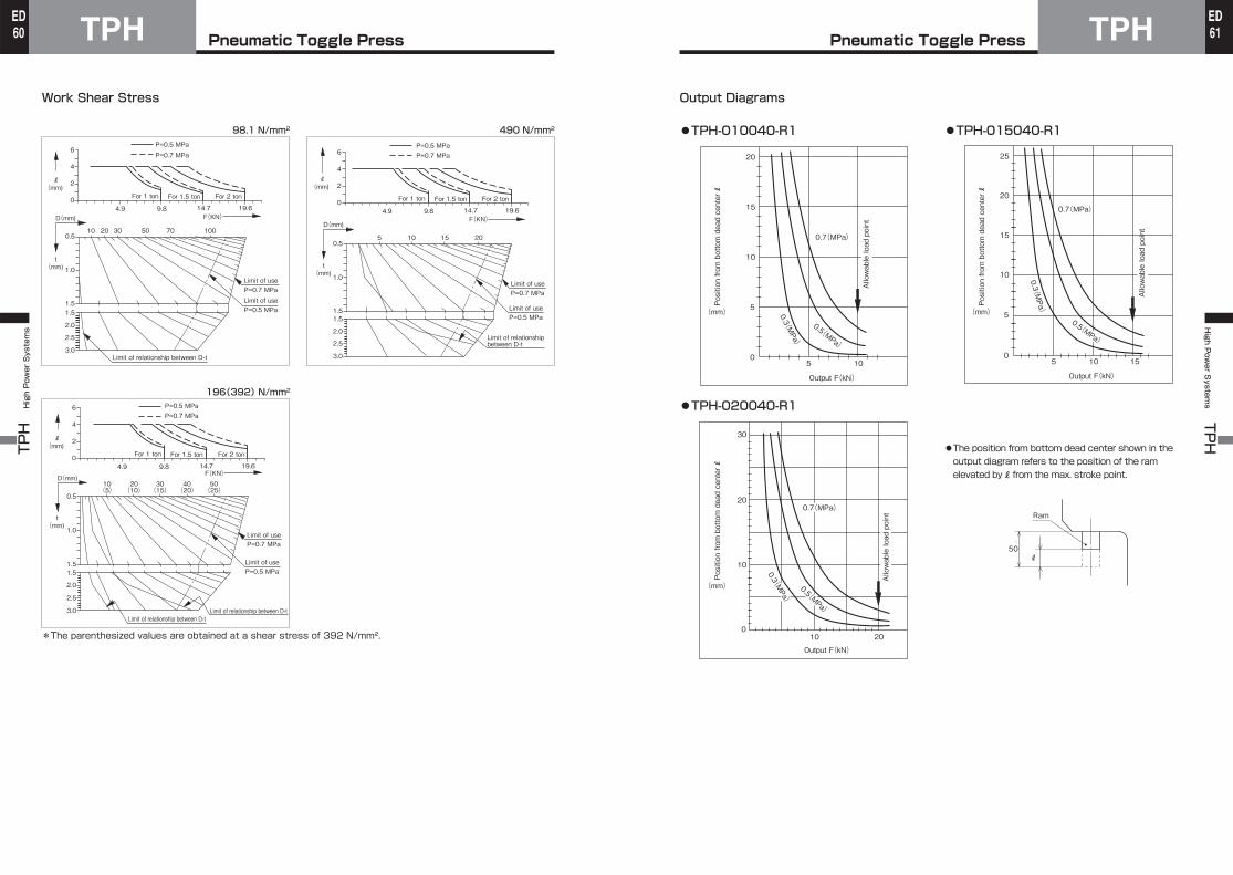
Pneumatic Toggle PressTPHTPH High Power Systems
60ED
Pneumatic Toggle Press TPHHigh P
ower S
ystems TPH
61ED
Work Shear Stress
98.1 N/mm2
196(392) N/mm2
490 N/mm2
*The parenthesized values are obtained at a shear stress of 392 N/mm².
6
4
4.9 9.8
10 20 30 70 10050
14.7F(KN)
19.6
For 1 ton For 2 tonFor 1.5 ton
2
0
0.5
1.0
1.51.5
2.0
2.5
3.0
P=0.5 MPaP=0.7 MPa
P=0.5 MPa
D(mm)
ℓ(mm)
t (mm)
ℓ(mm)
t (mm)
ℓ(mm)
t (mm)
P=0.7 MPaLimit of use
Limit of use
Limit of relationship between D-t
6
4
4.9 9.8
5 10 15 20
14.7F(KN)
19.6
2
0
0.5
1.0
1.51.5
2.0
2.5
3.0
P=0.5 MPaP=0.7 MPa
D(mm)
P=0.7 MPaLimit of use
P=0.5 MPaLimit of use
Limit of relationship between D-t
6
4
4.9 9.8
10 20 30 40 50(5) (10) (15) (20) (25)
14.7F(KN)
19.6
For 1 ton For 2 tonFor 1.5 ton
2
0
0.5
1.0
1.51.5
2.0
2.5
3.0
P=0.5 MPaP=0.7 MPa
P=0.5 MPa
D(mm)
P=0.7 MPaLimit of use
Limit of use
Limit of relationship between D-tLimit of relationship between D-t
For 1 ton For 2 tonFor 1.5 ton
Output Diagrams
●TPH-010040-R1 ●TPH-015040-R1
●TPH-020040-R1
●The position from bottom dead center shown in the output diagram refers to the position of the ram elevated by ℓ from the max. stroke point.
20
15
10
5
5 100
0.7(MPa)
0.3(MPa)
0.5(MPa)
Output F(kN)
Position from bottom dead center ℓ
(mm)
Position from bottom dead center ℓ
(mm)
Position from bottom dead center ℓ
(mm)
20
25
15
10
5
5 10 150
0.7(MPa) 0.3(MPa)
Output F(kN)
0.5(MPa)
10 20
20
30
10
0
Output F(kN)
Allowable load point
0.7(MPa)
0.3(MPa)
0.5(MPa)
Ram
50ℓ
Allowable load point
Allowable load point
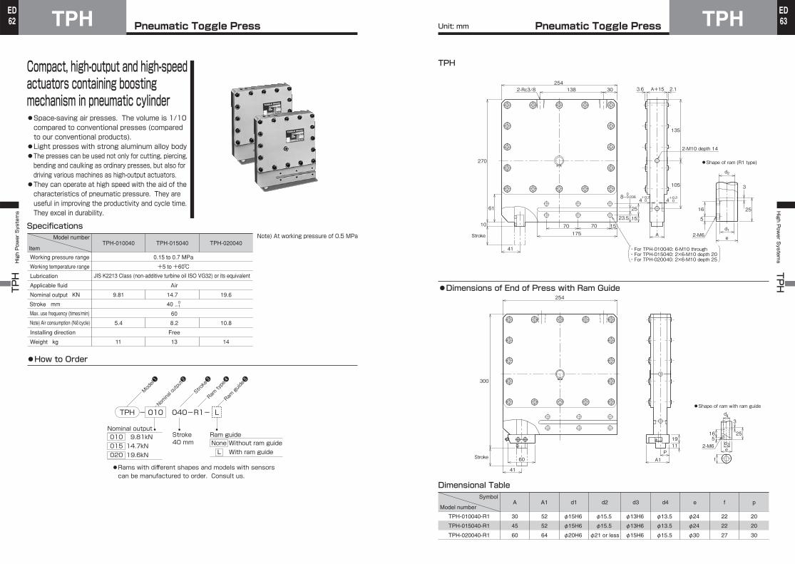
Pneumatic Toggle PressTPHTPH High Power Systems
62ED
Pneumatic Toggle Press TPHHigh P
ower S
ystems TPH
63ED
Stroke❸
Nominal outp
ut❷
Model❶
Ram type❹
Ram guide❺
Compact, high-output and high-speed actuators containing boosting mechanism in pneumatic cylinder●Space-saving air presses. The volume is 1/10 compared to conventional presses (compared to our conventional products).
●Light presses with strong aluminum alloy body●The presses can be used not only for cutting, piercing, bending and caulking as ordinary presses, but also for driving various machines as high-output actuators.
●They can operate at high speed with the aid of the characteristics of pneumatic pressure. They are useful in improving the productivity and cycle time.They excel in durability.
Specifications
●How to Order
Model number
Item
Working pressure range
Working temperature range
Lubrication Applicable fluid
Nominal output KN
Stroke mm
Max. use frequency (times/min) Note) Air consumption (Nℓ/cycle)
Installing direction
Weight kg
TPH-010040
9.81
5.4
11
0.15 to 0.7 MPa
+5 to +60℃ JIS K2213 Class (non-additive turbine oil ISO VG32) or its equivalent
Air
40
60
Free
13
TPH-015040
14.7
8.2
TPH-020040
19.6
10.8
14
0 -1
TPH - 010 040-R1- L
Nominal output 010 9.81kN 015 14.7kN 020 19.6kN
Ram guideNone Without ram guideL With ram guide
Stroke40 mm
●Rams with different shapes and models with sensors can be manufactured to order. Consult us.
Note) At working pressure of 0.5 MPa
●Dimensions of End of Press with Ram Guide
Symbol
Model number
TPH-010040-R1
TPH-015040-R1
TPH-020040-R1
A
30
45
60
A1
52
52
64
d1
φ15H6
φ15H6
φ20H6
d2
φ15.5
φ15.5
φ21 or less
d3
φ13H6
φ13H6
φ15H6
d4
φ13.5
φ13.5
φ15.5
e
φ24
φ24
φ30
f
22
22
27
p
20
20
30
Dimensional Table
254138 302-Rc3/8
41
A
270
10
Stroke
A+15
61
15
25
23.5
135
105
4
2-M10 depth 14
・For TPH-010040: 6-M10 through・For TPH-015040: 2×6-M10 depth 20・For TPH-020040: 2×6-M10 depth 25
+0.204
+0.20
8 0-0.036
17570 70 15
3.6 2.1
25
3
16
5
2-M6d1
d2
e
●Shape of ram (R1 type)
254
41
Stroke
300
1911
A1P
f
516 25
e
d4
d32-M6
60
3
●Shape of ram with ram guide
TPH
Unit: mm
High Power Systems H
igh Power S
ystems
Oil Pack Cylinders(Order Made)
HSP3…………………………ED66
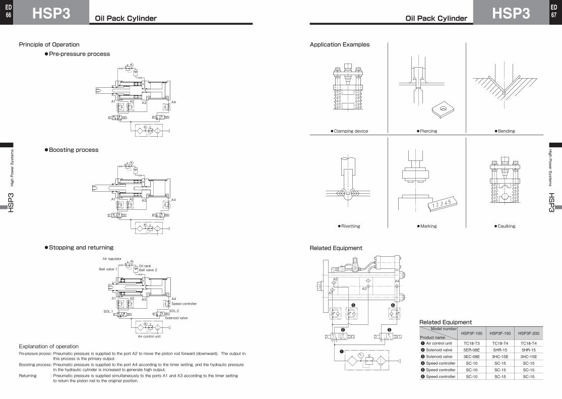
Oil Pack CylinderHSP3HSP3 High Power Systems
66ED
Oil Pack Cylinder HSP3High P
ower S
ystems HSP3
67ED
Principle of Operation
Explanation of operationPre-pressure process : Pneumatic pressure is supplied to the port A2 to move the piston rod forward (downward). The output in
this process is the primary output.Boosting process : Pneumatic pressure is supplied to the port A4 according to the timer setting, and the hydraulic pressure
in the hydraulic cylinder is increased to generate high output.Returning : Pneumatic pressure is supplied simultaneously to the ports A1 and A3 according to the timer setting
to return the piston rod to the original position.
●Pre-pressure process
●Boosting process
●Stopping and returning
A1 A2 A3 A4
A1 A2 A3 A4
Ball valve 1
Air regulator
Speed controller
Solenoid valve
Air control unit
Oil tankBall valve 2
A1 A2 A3 A4
SOL.2SOL.1
Application Examples
●Clamping device
●Rivetting ●Marking
●Piercing
●Caulking
●Bending
Related Equipment
Related Equipment
❶❷❸❹❺❻
Air control unit
Solenoid valve
Solenoid valve
Speed controller
Speed controller
Speed controller
Model number
Product nameHSP3F-100 HSP3F-150 HSP3F-200
TC18-T3
5ER-08E
3EC-08E
SC-10
SC-10
SC-10
TC18-T4
5HR-15
3HC-15E
SC-15
SC-15
SC-15
TC18-T4
5HR-15
3HC-15E
SC-15
SC-15
SC-15
A1
A2
A3
A4
❺
❷
❶
❸
❻
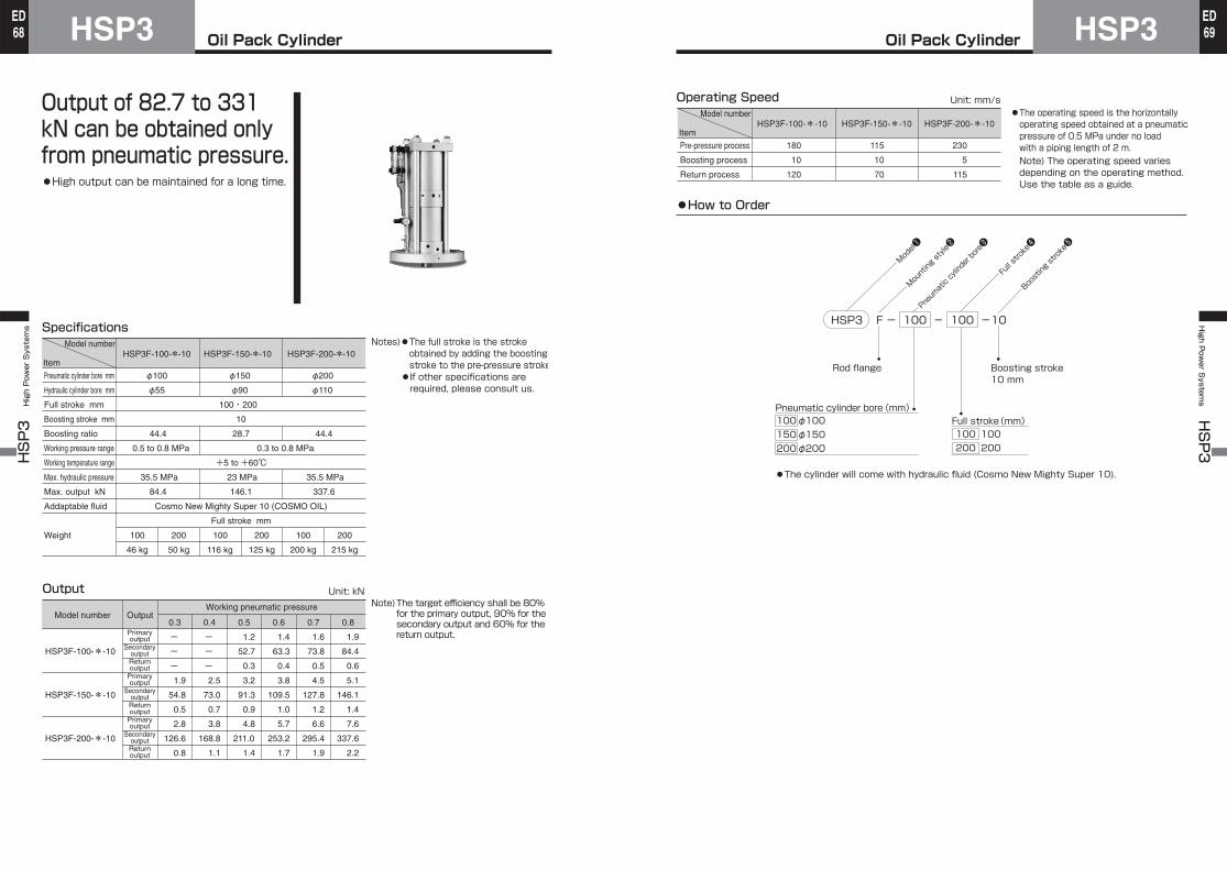
Oil Pack CylinderHSP3HSP3 High Power Systems
68ED
Oil Pack Cylinder HSP3High P
ower S
ystems HSP3
69ED
Output of 82.7 to 331 kN can be obtained only from pneumatic pressure.●High output can be maintained for a long time.
SpecificationsNotes)●The full stroke is the stroke
obtained by adding the boosting stroke to the pre-pressure stroke●If other specifications are required, please consult us.
Output
Model number
Item
Pneumatic cylinder bore mm
Hydraulic cylinder bore mm
Full stroke mm
Boosting stroke mm
Boosting ratio
Working pressure range
Working temperature range
Max. hydraulic pressure
Max. output kN
Addaptable fluid
Weight
HSP3F-100-*-10 HSP3F-150-*-10 HSP3F-200-*-10
φ100
φ55
44.4
0.5 to 0.8 MPa
35.5 MPa
84.4
φ150
φ90
28.7
23 MPa
146.1
φ200
φ110
44.4
35.5 MPa
337.6
100・200
10
0.3 to 0.8 MPa
+5 to +60℃
Cosmo New Mighty Super 10 (COSMO OIL)
Full stroke mm
100
46 kg
200
50 kg
100
116 kg
200
125 kg
100
200 kg
200
215 kg
HSP3F-100-*-10
HSP3F-150-*-10
HSP3F-200-*-10
Model number OutputWorking pneumatic pressure
ー
ー
ー
1.9
54.8
0.5
2.8
126.6
0.8
Primaryoutput
SecondaryoutputReturnoutput
Primaryoutput
SecondaryoutputReturnoutput
Primaryoutput
SecondaryoutputReturnoutput
1.2
52.7
0.3
3.2
91.3
0.9
4.8
211.0
1.4
ー
ー
ー
2.5
73.0
0.7
3.8
168.8
1.1
1.6
73.8
0.5
4.5
127.8
1.2
6.6
295.4
1.9
1.4
63.3
0.4
3.8
109.5
1.0
5.7
253.2
1.7
1.9
84.4
0.6
5.1
146.1
1.4
7.6
337.6
2.2
0.3 0.4 0.5 0.6 0.7 0.8
Note)The target efficiency shall be 80% for the primary output, 90% for the secondary output and 60% for the return output.
Unit: kN
Full s
troke❹
Pneuma
tic cy
linder bore❸
Mounting style❷
Model❶
Boosting stroke❺
HSP3 F - 100 - 100 -10
Pneumatic cylinder bore(mm)100φ100150φ150200φ200
Full stroke(mm) 100 100 200 200
Operating Speed●The operating speed is the horizontally operating speed obtained at a pneumatic pressure of 0.5 MPa under no load with a piping length of 2 m.Note) The operating speed varies depending on the operating method. Use the table as a guide.
Model number
ItemHSP3F-100-*-10 HSP3F-150-*-10 HSP3F-200-*-10
Pre-pressure process
Boosting process
Return process
180
10
120
115
10
70
230
5
115
●How to Order
Rod flange Boosting stroke10 mm
●The cylinder will come with hydraulic fluid (Cosmo New Mighty Super 10).
Unit: mm/s
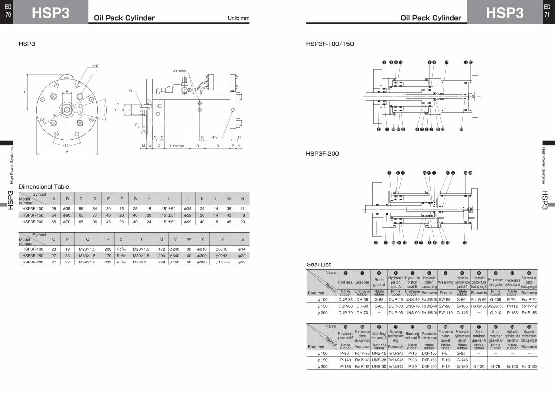
Oil Pack CylinderHSP3HSP3 High Power Systems
70ED
Oil Pack Cylinder HSP3High P
ower S
ystems HSP3
71ED
Unit: mm
HSP3
Dimensional Table
HSP3F-100
HSP3F-150
HSP3F-200
SymbolModelnumber
SymbolModelnumber
A B C D E F G H I J K L M N
28
54
65
55
65
65
64
77
96
30
40
48
15
20
26
25
40
40
15
20
24
15°±5° 15°±5° 15°±5°
φ34
φ59
φ69
24
28
40
14
14
8
35
43
45
11
8
20
φ35
φ60
φ70
HSP3F-100
HSP3F-150
HSP3F-200
23
27
27
19
23
32
M20×1.5
M30×1.5
M39×1.5
O P Q
200
179
233
Rc3/8
Rc1/2
Rc1/2
M20×1.5
M30×1.5
M36×2
R S T
172
204
229
φ240
φ340
φ450
U V
30
40
50
φ210
φ300
φ380
W X
φ60H8
φ90H8
φ140H8
Y
φ14
φ22
φ33
Z
8-Z
T
U
X
V
A
I
IY B
M W C
N O P 4-S H
D R E KL+stroke
G
F
J
Q
45°
Air vents
Pre-pressurepiston seal B
Boostingrod backup
ring
Boostingrod seal B
Pneumaticpiston seal
Pneumaticcylinder tube
gasket
Sealretainergasket B
Hydrauliccylinder tube
gasket B
Sealretainergasket A
Boostingrod seal A
Hydrauliccylinder tubebackup ring B
Pneumaticpistongasket
Pre-pressurepiston
backup ring BNitrilerubber Fluororesin Fluororesin FluororesinUrethane
rubberNitrilerubber
Nitrilerubber
Nitrilerubber
Nitrilerubber
Nitrilerubber
Nitrilerubber
Nitrilerubber
Name
Bore mm
Material
HSP3F-100/150
Seal List
HSP3F-200
φ100
φ150
φ200
Name
Bore mm
Material
❶
Rod sealHydraulic
pistonseal A
Hydraulicpistonseal B
Hydraulicpiston
backup ring
Hydrauliccylinder tube
gasket A
Pre-pressuretube gasket
Pre-pressurepiston seal A
Hydrauliccylinder tubebackup ring A
Bushgasket
Pre-pressurepiston
backup ring AWear ringScraper
❷ ❸ ❹ ❺ ❻ ❼ ❽ ❾ 10 11 12
DUP-35
DUP-60
DUP-70
DH-35
DH-60
DH-70
G-55
G-85
ー
DUP-45
DUP-80
DUP-95
UNS-40
UNS-70
UNS-90
For UNS-40
For UNS-70
For UNS-90
SW-55
SW-90
SW-110
G-60
G-105
G-145
For G-60
For G-105
ー
G-105
AS568-165
G-210
P-70
P-112
P-155
For P-70
For P-112
For P-155
φ100
φ150
φ200
13 14 15 16 17 18 19 20 21 22 23 24
P-90
P-140
P-185
For P-90
For P-140
For P-185
UNS-15
UNS-28
UNS-30
For UNS-15
For UNS-28
For UNS-30
P-15
P-28
P-30
DXP-100
DXP-150
DXP-200
P-8
P-10
P-15
G-95
G-145
G-190
ー
ー
G-120
ー
ー
G-75
ー
ー
G-120
ー
ー
For G-120
❸
❷ ❶ ❹❼❻❺1014 1516 1913
❷ ❶ ❹❼ ❻ ❺10 14 1516 1913
❽11 ❽❾ 17 182012
❽ 11 2324 21 1720 182012
Nitrilerubber PhenolFluororesin Fluororesin FluororesinUrethane
rubberNitrilerubber
Nitrilerubber
Nitrilerubber
Nitrilerubber
Nitrilerubber
Urethanerubber