Embed Size (px)
Citation preview
International Journal of Rotating Machinery, 10(4): 241–251, 2004Copyright c© Taylor & Francis Inc.ISSN: 1023-621X print / 1542-3034 onlineDOI: 10.1080/10236210490447502
Higher Order Rotating Cavitation in an Inducer
Akira Fujii, Seiji Azuma, Yoshiki Yoshida, Yoshinobu Tsujimoto,and Hironori HoriguchiOsaka University, Engineering Science, Osaka, Japan
Satoshi WatanabeKyushu University, Faculty of Engineering, Fukuoka, Japan
In the present study, a higher order rotating cavitationpredicted by the stability analysis was identified through themeasurements of inlet pressure fluctuations and blade stressfluctuations. The propagation speed ratio of the higher orderrotating cavitation is approximately 5, and the amplitude ofthe blade stress fluctuation caused by this rotating cavita-tion is the same level as that by the conventional rotatingcavitation. In addition, a higher order cavitation surge wasobserved at the transition point from the conventional to thehigher order rotating cavitation.
Keywords Blade stress fluctuation, Cavitation, Cavitaion surge,Inducer, Rotating cavitation
For the rocket engine turbopump, inducer is often placedupstream of the centrifugal impeller to improve the cavitationperformance. However, it often suffers from the cavitation in-stabilities such as rotating cavitation and cavitation surge. Untilnow, these cavitation instabilities were reported by many re-searchers since the super-synchronous shaft vibration and bladestress fluctuation caused by these cavitation instabilities are se-rious problems for the rocket engine turbopump (Kamijo et al.,1977; de Bernarldi et al., 1993; Tsujimoto et al., 1997; Bordelonet al., 1995; Arnone et al., 2001; Joussellin et al., 2001; Azumaet al., 2001).
Until now, the propagation speed ratio of conventional ro-tating cavitation observed until now is approximately 1.1–1.5.However, Watanabe et al. (1999) and Horiguchi et al. (2000)
Received 25 June 2002; accepted 1 July 2002.Address correspondence to Akira Fujii, Division of Mechanical Sci-
ence, Engineering Science, Osaka University, 1-3 Machikaneyama,Toyonaka, Osaka, 560-8531, Japan. E-mail: [email protected]
theoretically predicted the higher order rotating cavitationwhich has higher propagation speed ratio (about 3–6). In thepresent study, the higher order rotating cavitation with apropagation speed ratio of about 5 is reported. It was observ-ed under the experiment with modified inlet casing of theinducer.
This higher order rotating cavitation has very high propa-gation speed compared with that of the conventional one. It isnecessary to clarify the characteristics and the method of sup-pression about this rotating cavitation for the design of reliableinducer. In the present study, the characteristics of higher or-der rotating cavitation was clarified through the measurementsof casing wall pressure fluctuations and the blade stress fluc-tuations. On the other hand, Kamijo et al. (1993) succeeded insuppressing the conventional rotating cavitation by a modifica-tion of the inlet casing. The same method was applied to suppressthe higher order rotating cavitation.
EXPERIMENTAL APPARATUS AND PROCEDURE
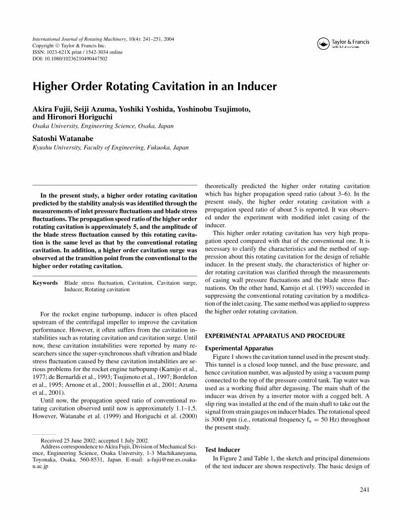
Experimental ApparatusFigure 1 shows the cavitation tunnel used in the present study.
This tunnel is a closed loop tunnel, and the base pressure, andhence cavitation number, was adjusted by using a vacuum pumpconnected to the top of the pressure control tank. Tap water wasused as a working fluid after degassing. The main shaft of theinducer was driven by a inverter motor with a cogged belt. Aslip ring was installed at the end of the main shaft to take out thesignal from strain gauges on inducer blades. The rotational speedis 3000 rpm (i.e., rotational frequency fn = 50 Hz) throughoutthe present study.
Test InducerIn Figure 2 and Table 1, the sketch and principal dimensions
of the test inducer are shown respectively. The basic design of
241
242 A. FUJII ET AL.
FIGURE 1Test facility. (a) Top view. (b) Side view.
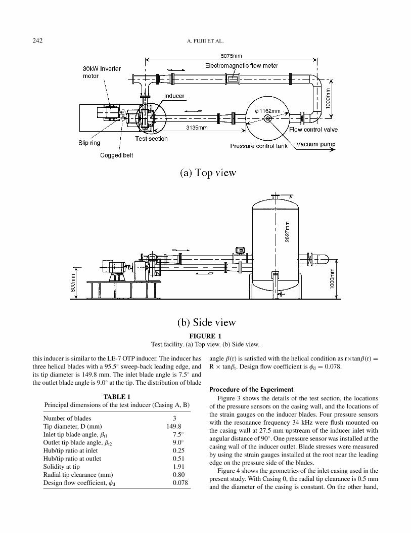
this inducer is similar to the LE-7 OTP inducer. The inducer hasthree helical blades with a 95.5◦ sweep-back leading edge, andits tip diameter is 149.8 mm. The inlet blade angle is 7.5◦ andthe outlet blade angle is 9.0◦ at the tip. The distribution of blade
TABLE 1Principal dimensions of the test inducer (Casing A, B)
Number of blades 3Tip diameter, D (mm) 149.8Inlet tip blade angle, βt1 7.5◦
Outlet tip blade angle, βt2 9.0◦
Hub/tip ratio at inlet 0.25Hub/tip ratio at outlet 0.51Solidity at tip 1.91Radial tip clearance (mm) 0.80Design flow coefficient, φd 0.078
angle β(r) is satisfied with the helical condition as r×tanβ(r) =R × tanβt. Design flow coefficient is φd = 0.078.
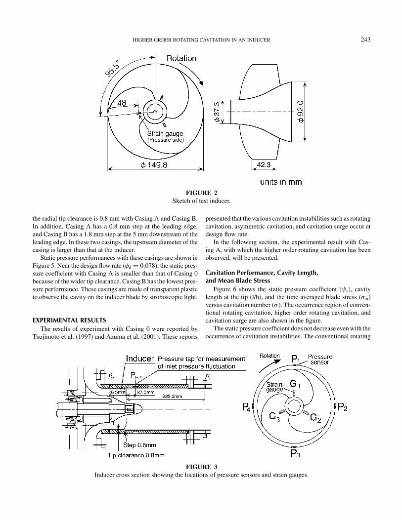
Procedure of the ExperimentFigure 3 shows the details of the test section, the locations
of the pressure sensors on the casing wall, and the locations ofthe strain gauges on the inducer blades. Four pressure sensorswith the resonance frequency 34 kHz were flush mounted onthe casing wall at 27.5 mm upstream of the inducer inlet withangular distance of 90◦. One pressure sensor was installed at thecasing wall of the inducer outlet. Blade stresses were measuredby using the strain gauges installed at the root near the leadingedge on the pressure side of the blades.
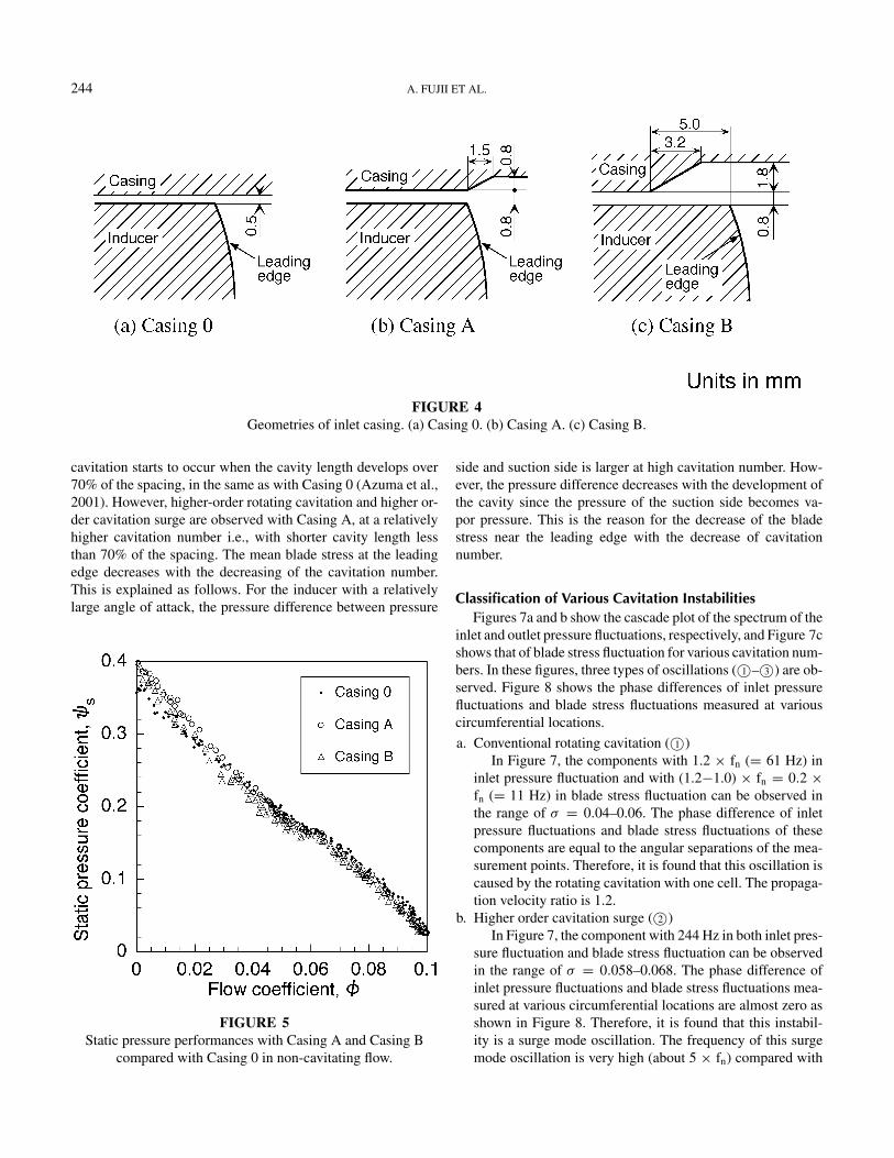
Figure 4 shows the geometries of the inlet casing used in thepresent study. With Casing 0, the radial tip clearance is 0.5 mmand the diameter of the casing is constant. On the other hand,
HIGHER ORDER ROTATING CAVITATION IN AN INDUCER 243
FIGURE 2Sketch of test inducer.
the radial tip clearance is 0.8 mm with Casing A and Casing B.In addition, Casing A has a 0.8 mm step at the leading edge,and Casing B has a 1.8 mm step at the 5 mm downstream of theleading edge. In these two casings, the upstream diameter of thecasing is larger than that at the inducer.
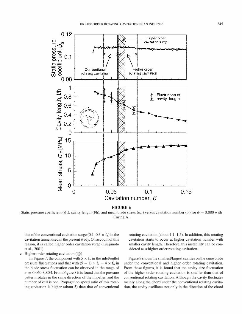
Static pressure performances with these casings are shown inFigure 5. Near the design flow rate (φd = 0.078), the static pres-sure coefficient with Casing A is smaller than that of Casing 0because of the wider tip clearance. Casing B has the lowest pres-sure performance. These casings are made of transparent plasticto observe the cavity on the inducer blade by stroboscopic light.
EXPERIMENTAL RESULTSThe results of experiment with Casing 0 were reported by
Tsujimoto et al. (1997) and Azuma et al. (2001). These reports
FIGURE 3Inducer cross section showing the locations of pressure sensors and strain gauges.
presented that the various cavitation instabilities such as rotatingcavitation, asymmetric cavitation, and cavitation surge occur atdesign flow rate.
In the following section, the experimental result with Cas-ing A, with which the higher order rotating cavitation has beenobserved, will be presented.
Cavitation Performance, Cavity Length,and Mean Blade Stress
Figure 6 shows the static pressure coefficient (ψs), cavitylength at the tip (l/h), and the time averaged blade stress (σm)versus cavitation number (σ ). The occurrence region of conven-tional rotating cavitation, higher order rotating cavitation, andcavitation surge are also shown in the figure.
The static pressure coefficient does not decrease even with theoccurrence of cavitation instabilities. The conventional rotating
244 A. FUJII ET AL.
FIGURE 4Geometries of inlet casing. (a) Casing 0. (b) Casing A. (c) Casing B.
cavitation starts to occur when the cavity length develops over70% of the spacing, in the same as with Casing 0 (Azuma et al.,2001). However, higher-order rotating cavitation and higher or-der cavitation surge are observed with Casing A, at a relativelyhigher cavitation number i.e., with shorter cavity length lessthan 70% of the spacing. The mean blade stress at the leadingedge decreases with the decreasing of the cavitation number.This is explained as follows. For the inducer with a relativelylarge angle of attack, the pressure difference between pressure
FIGURE 5Static pressure performances with Casing A and Casing B
compared with Casing 0 in non-cavitating flow.
side and suction side is larger at high cavitation number. How-ever, the pressure difference decreases with the development ofthe cavity since the pressure of the suction side becomes va-por pressure. This is the reason for the decrease of the bladestress near the leading edge with the decrease of cavitationnumber.
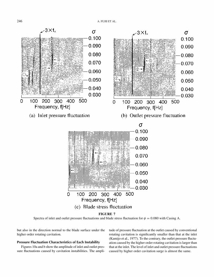
Classification of Various Cavitation InstabilitiesFigures 7a and b show the cascade plot of the spectrum of the
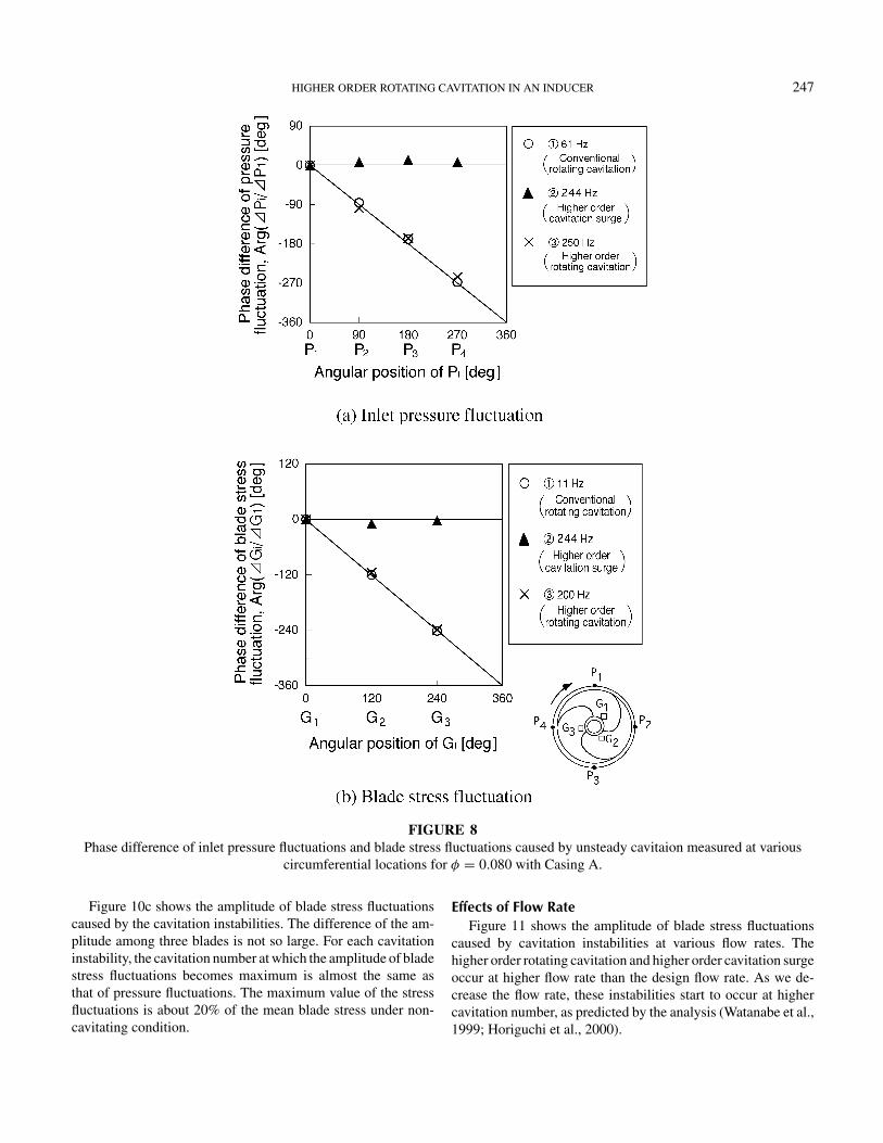
inlet and outlet pressure fluctuations, respectively, and Figure 7cshows that of blade stress fluctuation for various cavitation num-bers. In these figures, three types of oscillations (©1 –©3 ) are ob-served. Figure 8 shows the phase differences of inlet pressurefluctuations and blade stress fluctuations measured at variouscircumferential locations.
a. Conventional rotating cavitation (©1 )In Figure 7, the components with 1.2 × fn (= 61 Hz) in
inlet pressure fluctuation and with (1.2−1.0) × fn = 0.2 ×fn (= 11 Hz) in blade stress fluctuation can be observed inthe range of σ = 0.04–0.06. The phase difference of inletpressure fluctuations and blade stress fluctuations of thesecomponents are equal to the angular separations of the mea-surement points. Therefore, it is found that this oscillation iscaused by the rotating cavitation with one cell. The propaga-tion velocity ratio is 1.2.
b. Higher order cavitation surge (©2 )In Figure 7, the component with 244 Hz in both inlet pres-
sure fluctuation and blade stress fluctuation can be observedin the range of σ = 0.058–0.068. The phase difference ofinlet pressure fluctuations and blade stress fluctuations mea-sured at various circumferential locations are almost zero asshown in Figure 8. Therefore, it is found that this instabil-ity is a surge mode oscillation. The frequency of this surgemode oscillation is very high (about 5 × fn) compared with
HIGHER ORDER ROTATING CAVITATION IN AN INDUCER 245
FIGURE 6Static pressure coefficient (ψs), cavity length (l/h), and mean blade stress (σm) versus cavitation number (σ ) for φ = 0.080 with
Casing A.
that of the conventional cavitation surge (0.1–0.3 × fn) in thecavitation tunnel used in the present study. On account of thisreason, it is called higher order cavitation surge (Tsujimotoet al., 2001).
c. Higher order rotating cavitation (©3 )In Figure 7, the component with 5 × fn in the inlet/outlet
pressure fluctuations and that with (5 − 1) × fn = 4 × fn inthe blade stress fluctuation can be observed in the range ofσ = 0.060–0.084. From Figure 8 it is found that the pressurepattern rotates in the same direction of the impeller, and thenumber of cell is one. Propagation speed ratio of this rotat-ing cavitation is higher (about 5) than that of conventional
rotating cavitation (about 1.1–1.5). In addition, this rotatingcavitation starts to occur at higher cavitation number withsmaller cavity length. Therefore, this instability can be con-sidered as a higher order rotating cavitation.
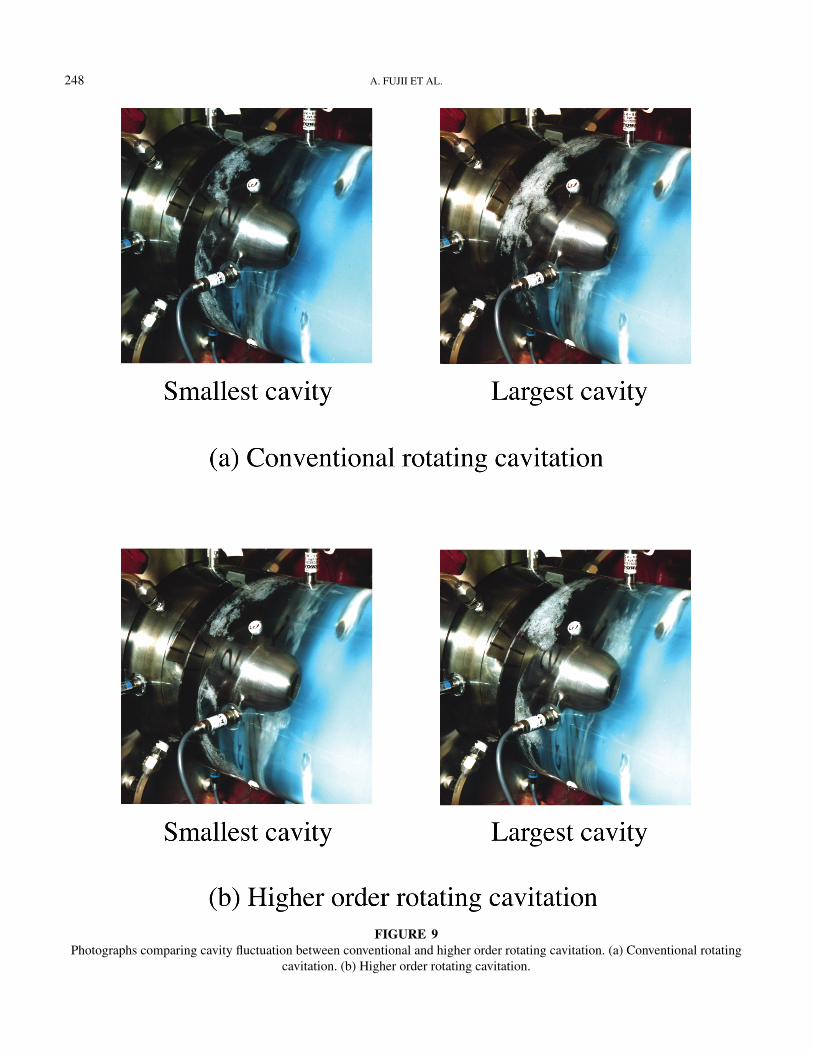
Figure 9 shows the smallest/largest cavities on the same bladeunder the conventional and higher order rotating cavitation.From these figures, it is found that the cavity size fluctuationof the higher order rotating cavitation is smaller than that ofconventional rotating cavitation. Although the cavity fluctuatesmainly along the chord under the conventional rotating cavita-tion, the cavity oscillates not only in the direction of the chord
246 A. FUJII ET AL.
FIGURE 7Spectra of inlet and outlet pressure fluctuations and blade stress fluctuation for φ = 0.080 with Casing A.
but also in the direction normal to the blade surface under thehigher order rotating cavitation.
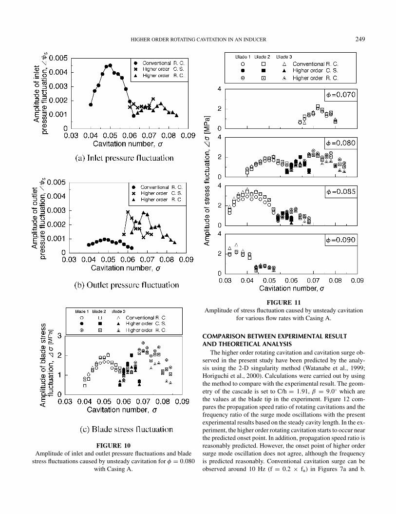
Pressure Fluctuation Characteristics of Each InstabilityFigures 10a and b show the amplitude of inlet and outlet pres-
sure fluctuations caused by cavitation instabilities. The ampli-
tude of pressure fluctuation at the outlet caused by conventionalrotating cavitation is significantly smaller than that at the inlet(Kamijo et al., 1977). To the contrary, the outlet pressure fluctu-ation caused by the higher order rotating cavitation is larger thanthat at the inlet. The level of inlet and outlet pressure fluctuationscaused by higher order cavitation surge is almost the same.
HIGHER ORDER ROTATING CAVITATION IN AN INDUCER 247
FIGURE 8Phase difference of inlet pressure fluctuations and blade stress fluctuations caused by unsteady cavitaion measured at various
circumferential locations for φ = 0.080 with Casing A.
Figure 10c shows the amplitude of blade stress fluctuationscaused by the cavitation instabilities. The difference of the am-plitude among three blades is not so large. For each cavitationinstability, the cavitation number at which the amplitude of bladestress fluctuations becomes maximum is almost the same asthat of pressure fluctuations. The maximum value of the stressfluctuations is about 20% of the mean blade stress under non-cavitating condition.
Effects of Flow RateFigure 11 shows the amplitude of blade stress fluctuations
caused by cavitation instabilities at various flow rates. Thehigher order rotating cavitation and higher order cavitation surgeoccur at higher flow rate than the design flow rate. As we de-crease the flow rate, these instabilities start to occur at highercavitation number, as predicted by the analysis (Watanabe et al.,1999; Horiguchi et al., 2000).
248 A. FUJII ET AL.
FIGURE 9Photographs comparing cavity fluctuation between conventional and higher order rotating cavitation. (a) Conventional rotating
cavitation. (b) Higher order rotating cavitation.
HIGHER ORDER ROTATING CAVITATION IN AN INDUCER 249
FIGURE 10Amplitude of inlet and outlet pressure fluctuations and blade
stress fluctuations caused by unsteady cavitation for φ = 0.080with Casing A.
FIGURE 11Amplitude of stress fluctuation caused by unsteady cavitation
for various flow rates with Casing A.
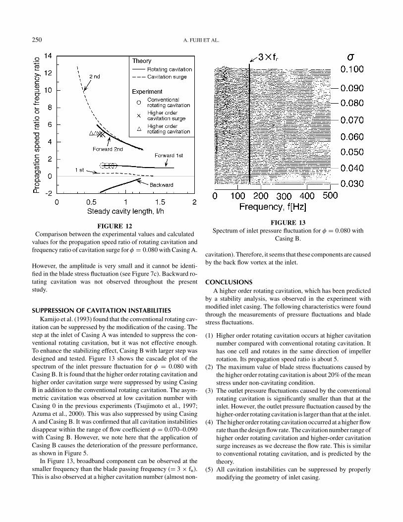
COMPARISON BETWEEN EXPERIMENTAL RESULTAND THEORETICAL ANALYSIS
The higher order rotating cavitation and cavitation surge ob-served in the present study have been predicted by the analy-sis using the 2-D singularity method (Watanabe et al., 1999;Horiguchi et al., 2000). Calculations were carried out by usingthe method to compare with the experimental result. The geom-etry of the cascade is set to C/h = 1.91, β = 9.0◦ which arethe values at the blade tip in the experiment. Figure 12 com-pares the propagation speed ratio of rotating cavitations and thefrequency ratio of the surge mode oscillations with the presentexperimental results based on the steady cavity length. In the ex-periment, the higher order rotating cavitation starts to occur nearthe predicted onset point. In addition, propagation speed ratio isreasonably predicted. However, the onset point of higher ordersurge mode oscillation does not agree, although the frequencyis predicted reasonably. Conventional cavitation surge can beobserved around 10 Hz (f = 0.2 × fn) in Figures 7a and b.
250 A. FUJII ET AL.
FIGURE 12Comparison between the experimental values and calculated
values for the propagation speed ratio of rotating cavitation andfrequency ratio of cavitation surge for φ = 0.080 with Casing A.
However, the amplitude is very small and it cannot be identi-fied in the blade stress fluctuation (see Figure 7c). Backward ro-tating cavitation was not observed throughout the presentstudy.
SUPPRESSION OF CAVITATION INSTABILITIESKamijo et al. (1993) found that the conventional rotating cav-
itation can be suppressed by the modification of the casing. Thestep at the inlet of Casing A was intended to suppress the con-ventional rotating cavitation, but it was not effective enough.To enhance the stabilizing effect, Casing B with larger step wasdesigned and tested. Figure 13 shows the cascade plot of thespectrum of the inlet pressure fluctuation for φ = 0.080 withCasing B. It is found that the higher order rotating cavitation andhigher order cavitation surge were suppressed by using CasingB in addition to the conventional rotating cavitation. The asym-metric cavitation was observed at low cavitation number withCasing 0 in the previous experiments (Tsujimoto et al., 1997;Azuma et al., 2000). This was also suppressed by using CasingA and Casing B. It was confirmed that all cavitation instabilitiesdisappear within the range of flow coefficient φ = 0.070–0.090with Casing B. However, we note here that the application ofCasing B causes the deterioration of the pressure performance,as shown in Figure 5.
In Figure 13, broadband component can be observed at thesmaller frequency than the blade passing frequency (= 3 × fn).This is also observed at a higher cavitation number (almost non-
FIGURE 13Spectrum of inlet pressure fluctuation for φ = 0.080 with
Casing B.
cavitation). Therefore, it seems that these components are causedby the back flow vortex at the inlet.
CONCLUSIONSA higher order rotating cavitation, which has been predicted
by a stability analysis, was observed in the experiment withmodified inlet casing. The following characteristics were foundthrough the measurements of pressure fluctuations and bladestress fluctuations.
(1) Higher order rotating cavitation occurs at higher cavitationnumber compared with conventional rotating cavitation. Ithas one cell and rotates in the same direction of impellerrotation. Its propagation speed ratio is about 5.
(2) The maximum value of blade stress fluctuations caused bythe higher order rotating cavitation is about 20% of the meanstress under non-cavitating condition.
(3) The outlet pressure fluctuations caused by the conventionalrotating cavitation is significantly smaller than that at theinlet. However, the outlet pressure fluctuation caused by thehigher-order rotating cavitation is larger than that at the inlet.
(4) The higher order rotating cavitation occurred at a higher flowrate than the design flow rate. The cavitation number range ofhigher order rotating cavitation and higher-order cavitationsurge increases as we decrease the flow rate. This is similarto conventional rotating cavitation, and is predicted by thetheory.
(5) All cavitation instabilities can be suppressed by properlymodifying the geometry of inlet casing.

HIGHER ORDER ROTATING CAVITATION IN AN INDUCER 251
ACKNOWLEDGMENTSThe authors would like to thank Mr. Tomoatsu Inoue of
Kyowa Electronic Instruments CO., LTD. for his experimen-tal support and advice. Mr. Shigeaki Miyata and Mr. YusukeKawamura’s support in conducting experiments are also ac-knowledged. This study is supported by the Grand-in-Aid forScience Research of the Ministry of Education, Science, Sports,and Culture, and the Hatakeyama Foundation.
NOMENCLATURED inducer diameterf frequency of pressure fluctuations or blade stress fluctua-
tionsfn shaft rotational frequencyGi measurement points of blade stress (i = 1–3)h tip blade spacingl cavity length at the tipp1 pressure at inletp1t total pressure at inletp2 pressure at outletpv vapor pressure�p pressure fluctuation (zero-to-peak)Pi measurement points of the pressure fluctuation (i = 1–4)r radiusR blade tip radiusUt peripheral speed of inducer tip = πDfn
v1 axial velocity at inducer inlet = flow rate/inlet areaα incidence angle, i.e., angle between the inlet relative ve-
locity and the blade = βt1− tan−1φ
β blade angleβt tip blade angle (βt1: inlet tip blade angle; βt2: outlet tip
blade angle)ρ densityσ cavitation number = (p1 − pv)/(ρU2
t /2)σm mean stress of blade [MPa]�σ blade stress fluctuation (zero-to-peak)φ flow coefficient = v1/Ut
φd design flow coefficientψs static pressure coefficient = (p2 − p1t)/(ρU2
t )
�ψ coefficient of pressure fluctuations = �p/(ρU2t ) (zero-to-
peak)
REFERENCESArnone, A., Boncinelli, P., Capuani, A., Spano, E., and Rebattet, C.
2001. “ARIANE 5” TPLOX inducer design strategies to enhancecavitating performance. Proceedings of 4th International Symposiumon Cavitation, Session B7. 004, Pasadena, California.
Azuma, S., Yoshida, Y., and Tsujimoto, Y. 2001. Unsteady bladestress due to rotating cavitation in an inducer. Turbomachinery (inJapanese) 29(3):147–154.
de Bernaldi, J., Joussellin, F., and Von Kaenel, A. 1993. Experimen-tal analysis of instabilities related to cavitation in a turbopump in-ducer. The 1st International Symposium Pump Noise Vibration, 1–9.
Bordelon, Jr., W. J., Gaddis, S. W., and Nesman, T. E. 1995. Cavita-tion enviromental of the alternate high pressure oxygen turbopumpinducer. ASME FED-Vol. 210, 39–46.
Horiguchi, H., Watanebe, S., and Tsujimoto, Y. 2000. A linear stabilityanalysis of cavitation in a finite blade count impeller. ASME Journalof Fluids Engineering 122(4):798–805.
Joussellin, F., Courtot, Y., Coutier-Delgosha, O., and Reboud, J. L.2001. Cavitating inducer instabilities: Experimental analysis and 2Dnumerical simulation of unsteady flow in blade cascade. Proceed-ings of 4th International Symposium on Cavitation, Session B8. 002,Pasadena, California.
Kamijo, K., Shimura, T., and Watanabe, M. 1977. An experimental in-vestigation of cavitating inducer instability. ASME Paper 77-WA/FE-14.
Kamijo, K., Yoshida, M., and Tsujimoto, Y. 1993. Hydraulic and me-chanical performance of LE-7 LOX pump inducer. AIAA Journal ofPropulsion and Power 9(6):819–826.
Tsujimoto, Y., Yoshida, Y., Maekawa, Y., Watanabe, S., and Hashimoto,T. 1997. Observations of oscillating cavitations of an inducer. ASMEJournal of Fluids Engineering 119(4):775–781.
Tsujimoto, Y. 2001. Simple rules for cavitation instabilities in turboma-chinery. Proceedings of 4th International Symposium on Cavitation,Lecture 006, Pasadena, California.
Watanabe, S., Sato, K., Tsujimoto, Y., and Kamijo, K. 1999. Analysisof rotating cavitation in a finite pitch cascade using a closed cavitymodel and a singularity method. ASME Journal of Fluids Engineer-ing 121:834–840.

International Journal of
AerospaceEngineeringHindawi Publishing Corporationhttp://www.hindawi.com Volume 2010
RoboticsJournal of
Hindawi Publishing Corporationhttp://www.hindawi.com Volume 2014
Hindawi Publishing Corporationhttp://www.hindawi.com Volume 2014
Active and Passive Electronic Components
Control Scienceand Engineering
Journal of
Hindawi Publishing Corporationhttp://www.hindawi.com Volume 2014
International Journal of
RotatingMachinery
Hindawi Publishing Corporationhttp://www.hindawi.com Volume 2014
Hindawi Publishing Corporation http://www.hindawi.com
Journal ofEngineeringVolume 2014
Submit your manuscripts athttp://www.hindawi.com
VLSI Design
Hindawi Publishing Corporationhttp://www.hindawi.com Volume 2014
Hindawi Publishing Corporationhttp://www.hindawi.com Volume 2014
Shock and Vibration
Hindawi Publishing Corporationhttp://www.hindawi.com Volume 2014
Civil EngineeringAdvances in
Acoustics and VibrationAdvances in
Hindawi Publishing Corporationhttp://www.hindawi.com Volume 2014
Hindawi Publishing Corporationhttp://www.hindawi.com Volume 2014
Electrical and Computer Engineering
Journal of
Advances inOptoElectronics
Hindawi Publishing Corporation http://www.hindawi.com
Volume 2014
The Scientific World JournalHindawi Publishing Corporation http://www.hindawi.com Volume 2014
SensorsJournal of
Hindawi Publishing Corporationhttp://www.hindawi.com Volume 2014
Modelling & Simulation in EngineeringHindawi Publishing Corporation http://www.hindawi.com Volume 2014
Hindawi Publishing Corporationhttp://www.hindawi.com Volume 2014
Chemical EngineeringInternational Journal of Antennas and
Propagation
International Journal of
Hindawi Publishing Corporationhttp://www.hindawi.com Volume 2014
Hindawi Publishing Corporationhttp://www.hindawi.com Volume 2014
Navigation and Observation
International Journal of
Hindawi Publishing Corporationhttp://www.hindawi.com Volume 2014
DistributedSensor Networks
International Journal of


![Cavitation Noise[1]](https://img.pdfslide.tips/doc/110x75/577cd69c1a28ab9e789cc836/cavitation-noise1.jpg)