Embed Size (px)
Citation preview

How to Verify Manual-J Accuracy& Properly Select Equipment
RESNET Conference - 2014
Isaac Savage, CEMTraining Development Director
Home Energy Partners
ABOUT US
Home Energy Partners develops and distributes training curriculum for the HVAC and Building Performance contracting industry.
Topic include:
Manual-J, S, D, & T
HVAC Design Software (Wrightsoft & Elite)
RESNET HERS Training
BPI Training
Home Performance Contracting
WHAT WE’LL COVER…
Design is required by…
Common challenges
The variables that matter
Reports for Wrightsoft & Elite
Manual-S basics
Start-to-finish equipment selection example
Demo of a Manual-S spreadsheet tool
WHO REQUIRES LOAD CALCULATIONS? Required by Programs ENERGY STAR Version 3
LEED for Homes
Utility Rebates
Required by Building Code! 2006, 2009, 2012 IECC
Many programs require 3rd
party review.
COMMON CHALLENGES
Tracking down the information in reports.
Some variables don’t show up on the reports.
Sometimes things just look funny on the reports. “What does that mean?”
VARIABLES THAT MATTER Design conditions
Envelope details
Ductwork specifications
Internal Loads
Infiltration
Ventilation
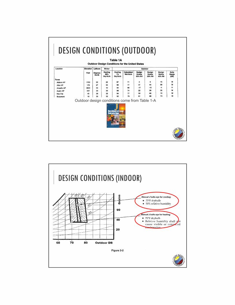
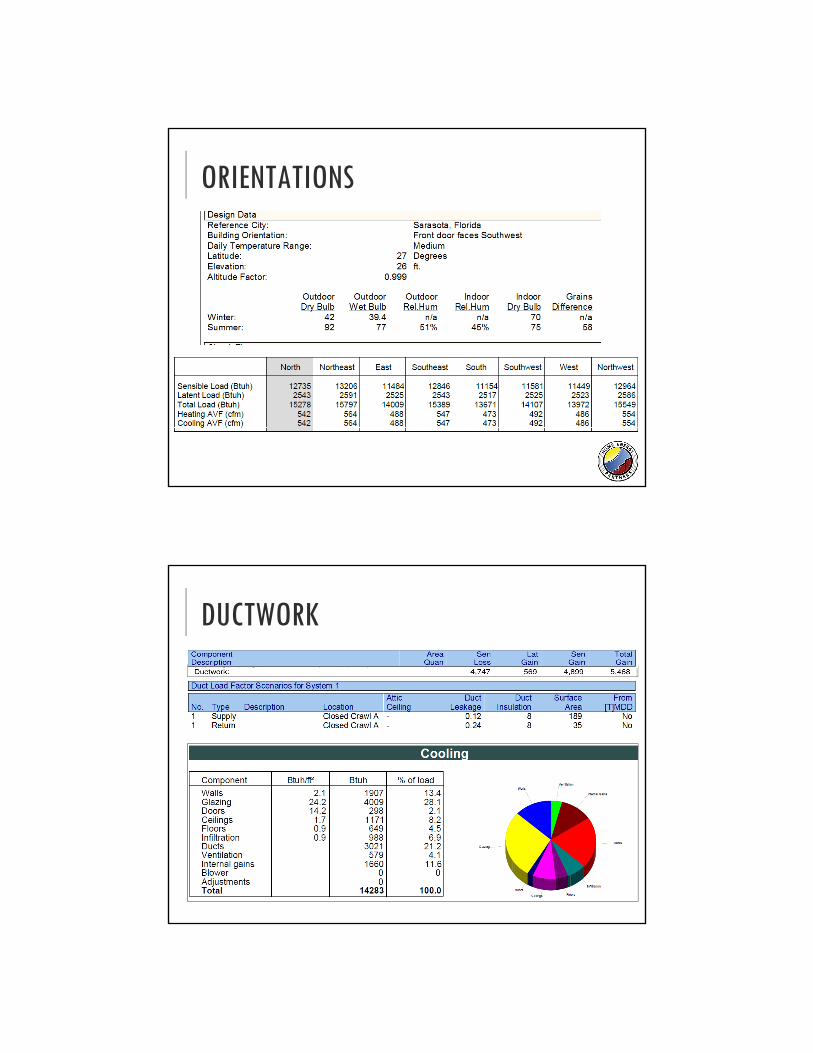
DESIGN CONDITIONS (OUTDOOR)
Outdoor design conditions come from Table 1-A
DESIGN CONDITIONS (INDOOR)
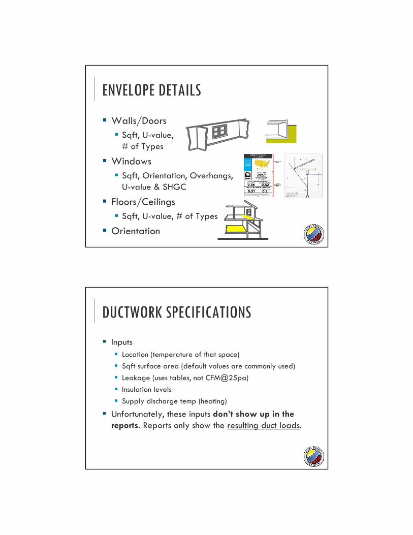
ENVELOPE DETAILS
Walls/Doors Sqft, U-value,
# of Types
Windows Sqft, Orientation, Overhangs,
U-value & SHGC
Floors/Ceilings Sqft, U-value, # of Types
Orientation
DUCTWORK SPECIFICATIONS
Inputs Location (temperature of that space)
Sqft surface area (default values are commonly used)
Leakage (uses tables, not CFM@25pa)
Insulation levels
Supply discharge temp (heating)
Unfortunately, these inputs don’t show up in the reports. Reports only show the resulting duct loads.
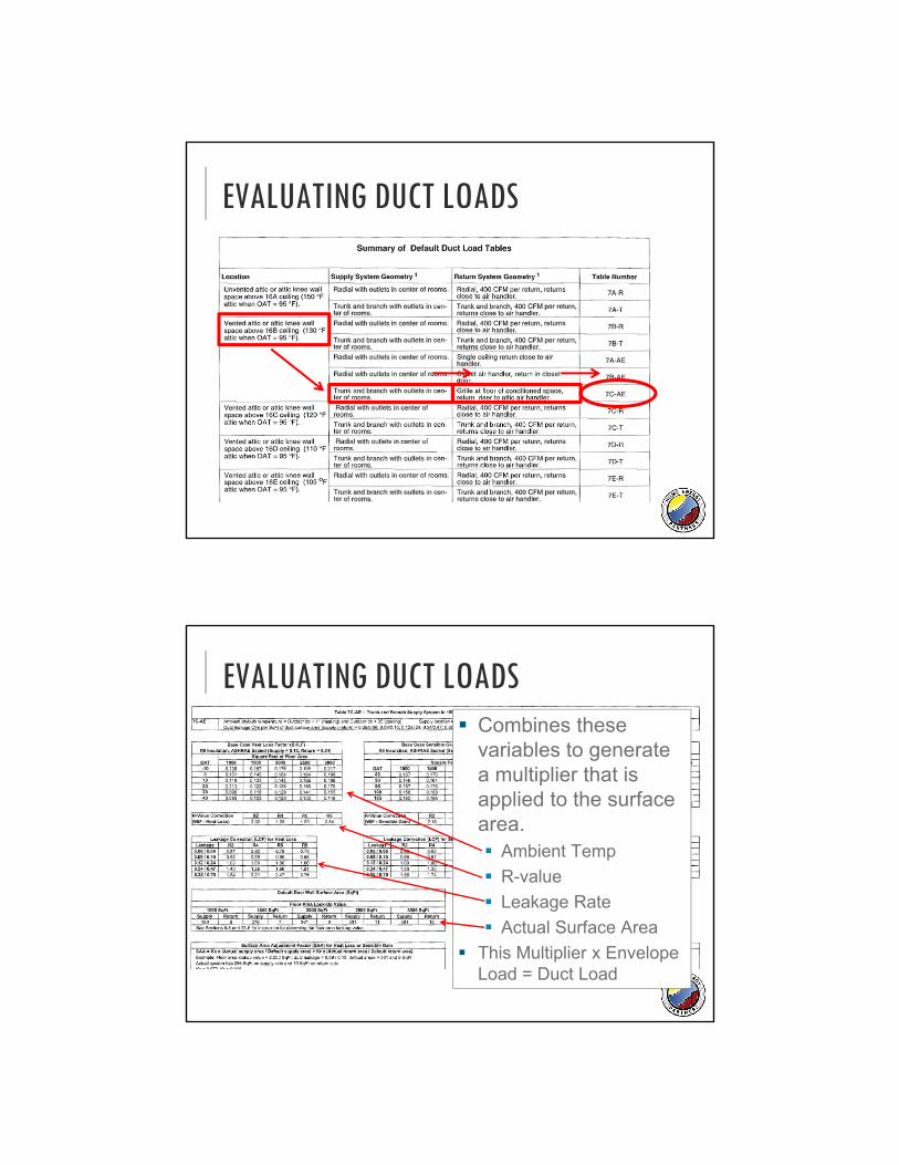
EVALUATING DUCT LOADS
EVALUATING DUCT LOADS Combines these
variables to generate a multiplier that is applied to the surface area. Ambient Temp
R-value
Leakage Rate
Actual Surface Area
This Multiplier x Envelope Load = Duct Load
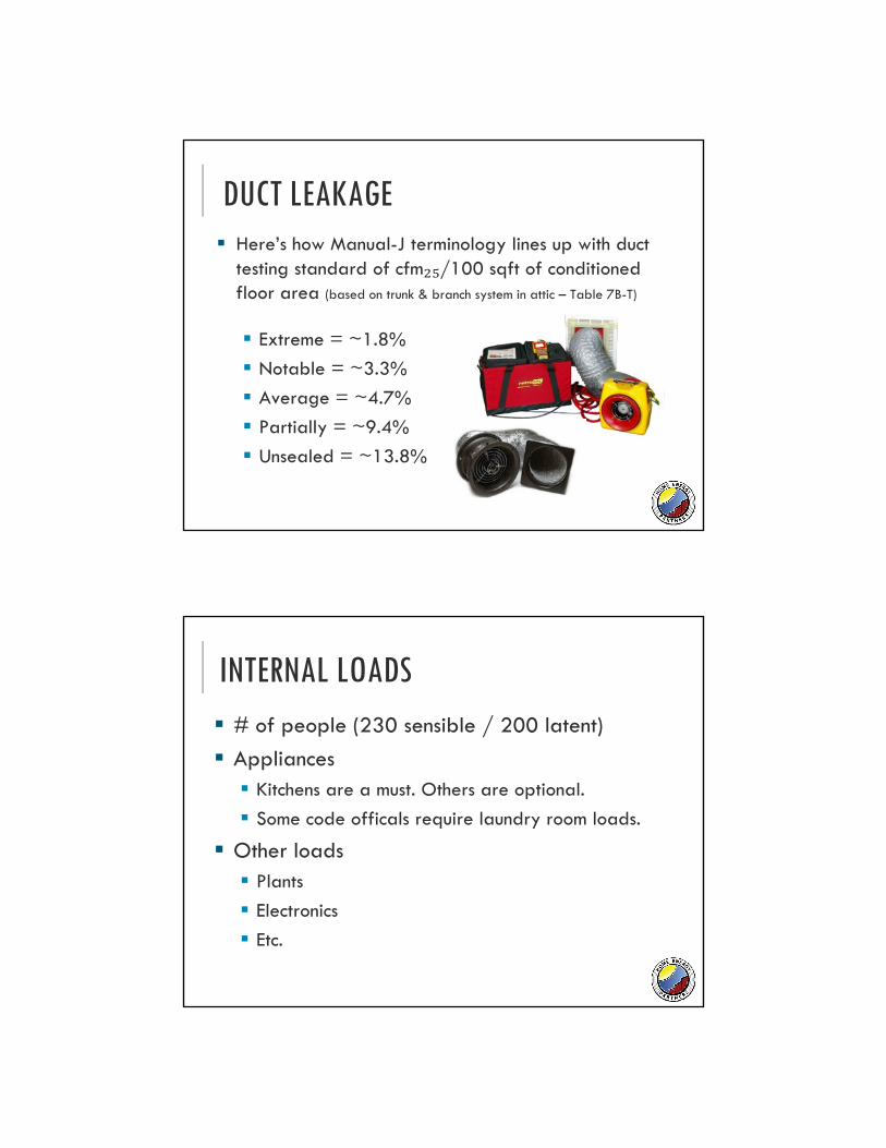
DUCT LEAKAGE Here’s how Manual-J terminology lines up with duct
testing standard of cfm₂₅/100 sqft of conditioned floor area (based on trunk & branch system in attic – Table 7B-T)
Extreme = ~1.8%
Notable = ~3.3%
Average = ~4.7%
Partially = ~9.4%
Unsealed = ~13.8%
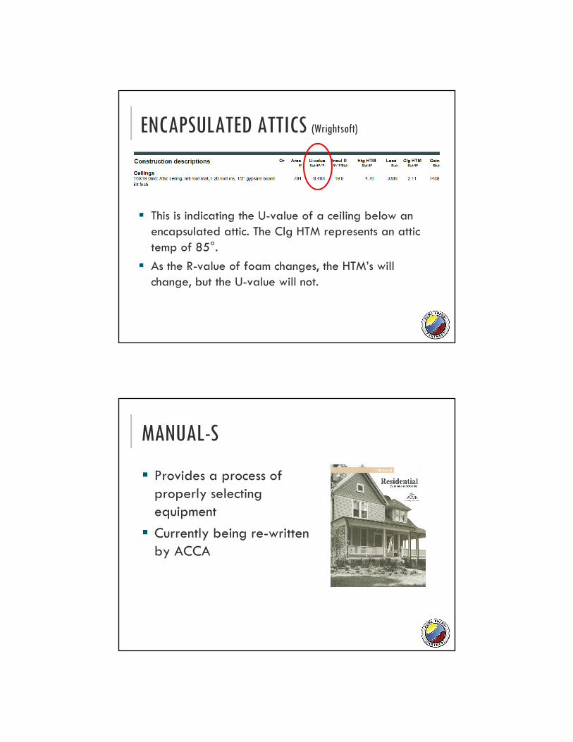
INTERNAL LOADS # of people (230 sensible / 200 latent)
Appliances Kitchens are a must. Others are optional.
Some code officals require laundry room loads.
Other loads Plants
Electronics
Etc.
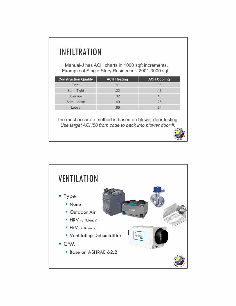
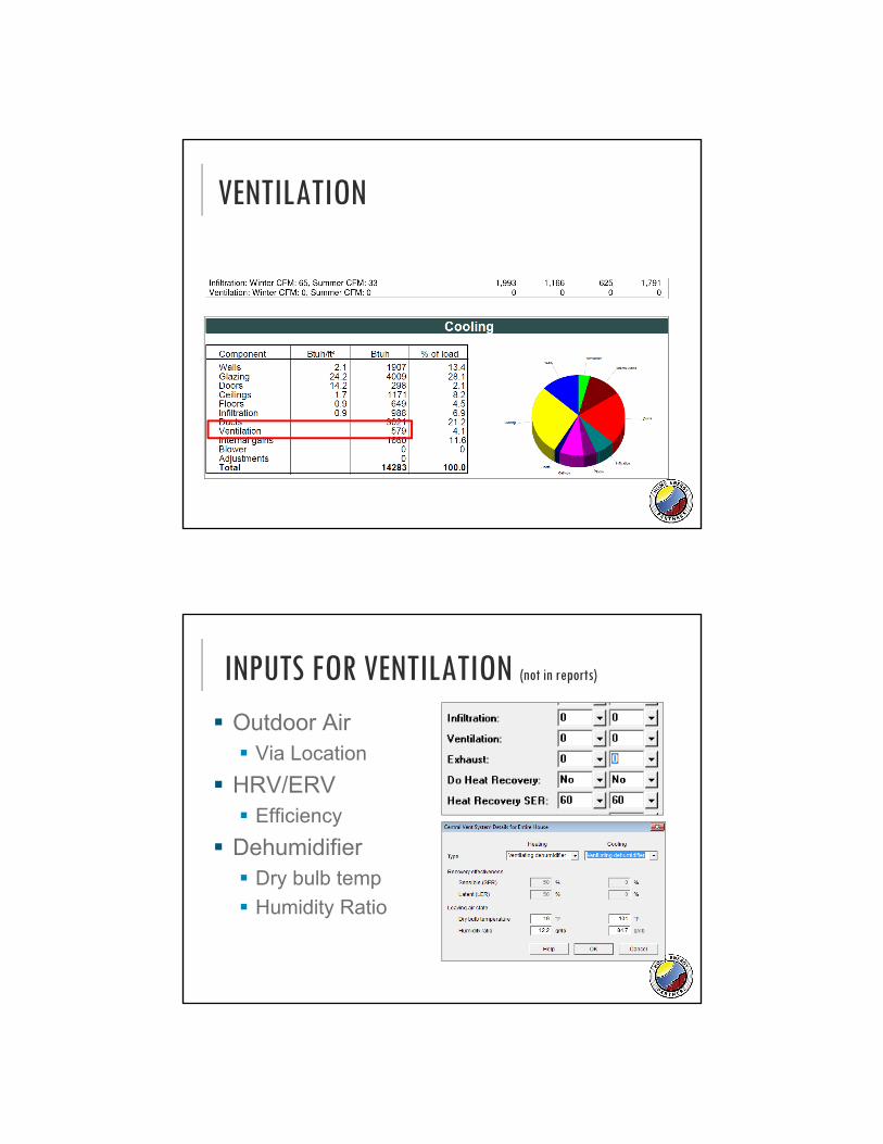
INFILTRATION
Construction Quality ACH Heating ACH Cooling
Tight .11 .06
Semi-Tight .22 .11
Average .32 .16
Semi-Loose .49 .25
Loose .66 .34
The most accurate method is based on blower door testing.Use target ACH50 from code to back into blower door #.
Manual-J has ACH charts in 1000 sqft increments.Example of Single Story Residence - 2001-3000 sqft
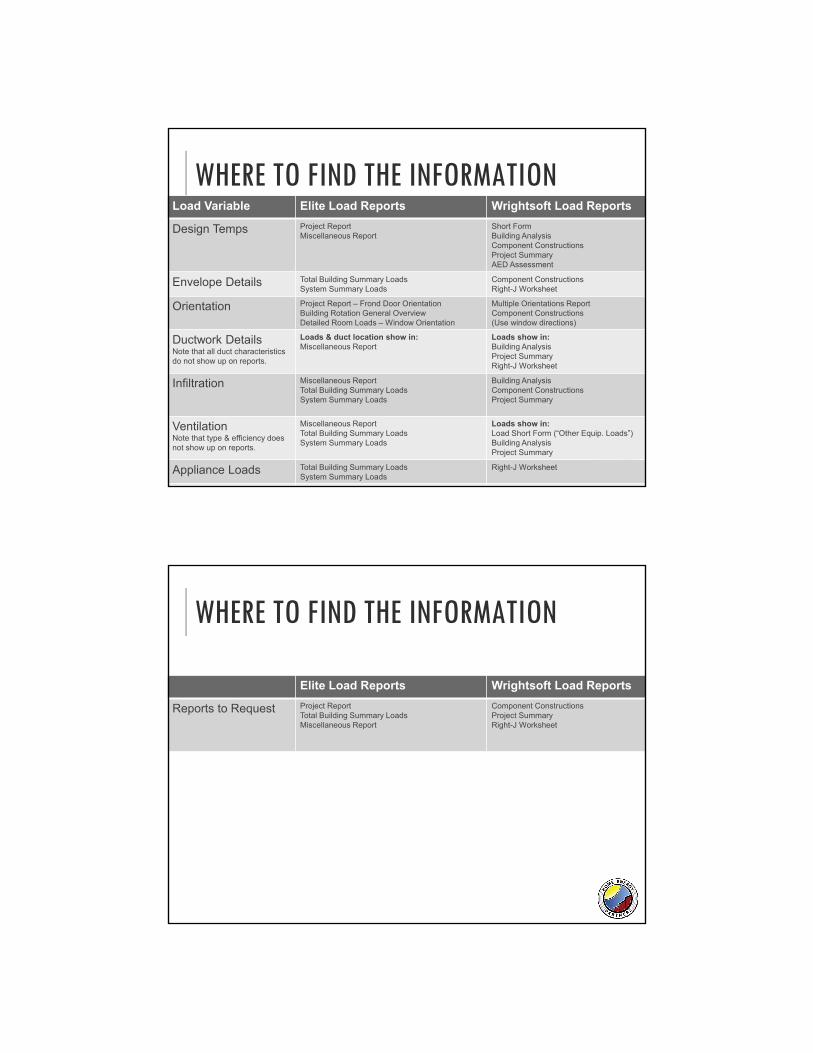
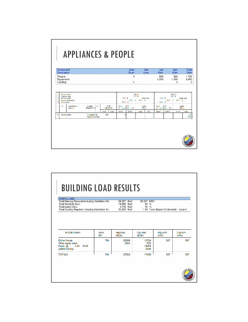
VENTILATION
Type None
Outdoor Air
HRV (efficiency)
ERV (efficiency)
Ventilating Dehumidifier
CFM Base on ASHRAE 62.2
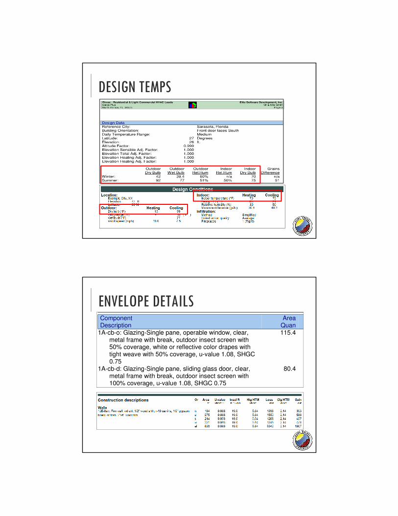
WHERE TO FIND THE INFORMATIONLoad Variable Elite Load Reports Wrightsoft Load Reports
Design Temps Project ReportMiscellaneous Report
Short FormBuilding AnalysisComponent ConstructionsProject SummaryAED Assessment
Envelope Details Total Building Summary LoadsSystem Summary Loads
Component ConstructionsRight-J Worksheet
Orientation Project Report – Frond Door OrientationBuilding Rotation General OverviewDetailed Room Loads – Window Orientation
Multiple Orientations ReportComponent Constructions(Use window directions)
Ductwork DetailsNote that all duct characteristics do not show up on reports.
Loads & duct location show in:Miscellaneous Report
Loads show in:Building AnalysisProject SummaryRight-J Worksheet
Infiltration Miscellaneous ReportTotal Building Summary LoadsSystem Summary Loads
Building AnalysisComponent ConstructionsProject Summary
VentilationNote that type & efficiency does not show up on reports.
Miscellaneous ReportTotal Building Summary LoadsSystem Summary Loads
Loads show in:Load Short Form (“Other Equip. Loads”)Building AnalysisProject Summary
Appliance Loads Total Building Summary LoadsSystem Summary Loads
Right-J Worksheet
WHERE TO FIND THE INFORMATION
Elite Load Reports Wrightsoft Load Reports
Reports to Request Project ReportTotal Building Summary LoadsMiscellaneous Report
Component ConstructionsProject SummaryRight-J Worksheet
DESIGN TEMPS
ENVELOPE DETAILS
ORIENTATIONS
DUCTWORK
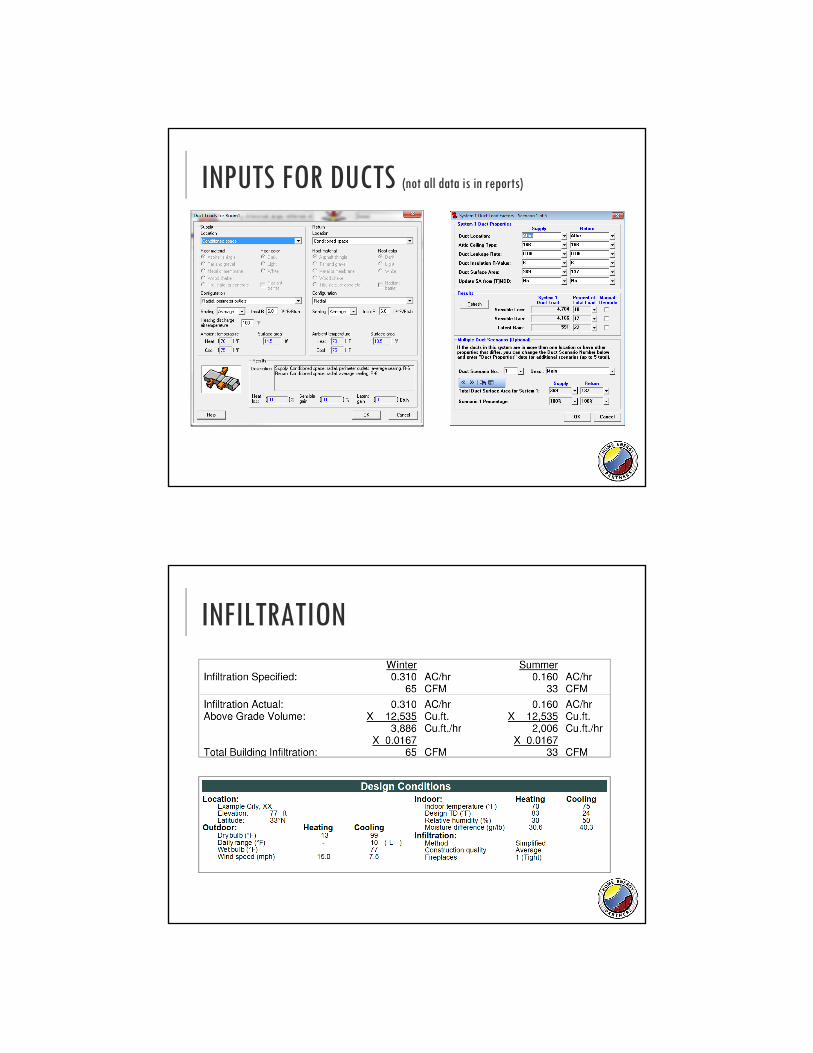
INPUTS FOR DUCTS (not all data is in reports)
Location (temp)
Leakage
Insulation
Surface Area
Supply Air Temp
INFILTRATION
VENTILATION
INPUTS FOR VENTILATION (not in reports)
Outdoor Air Via Location
HRV/ERV Efficiency
Dehumidifier Dry bulb temp
Humidity Ratio
APPLIANCES & PEOPLE
BUILDING LOAD RESULTS
ENCAPSULATED ATTICS (Wrightsoft)
This is indicating the U-value of a ceiling below an encapsulated attic. The Clg HTM represents an attic temp of 85°.
As the R-value of foam changes, the HTM’s will change, but the U-value will not.
MANUAL-S
Provides a process of properly selecting equipment
Currently being re-written by ACCA
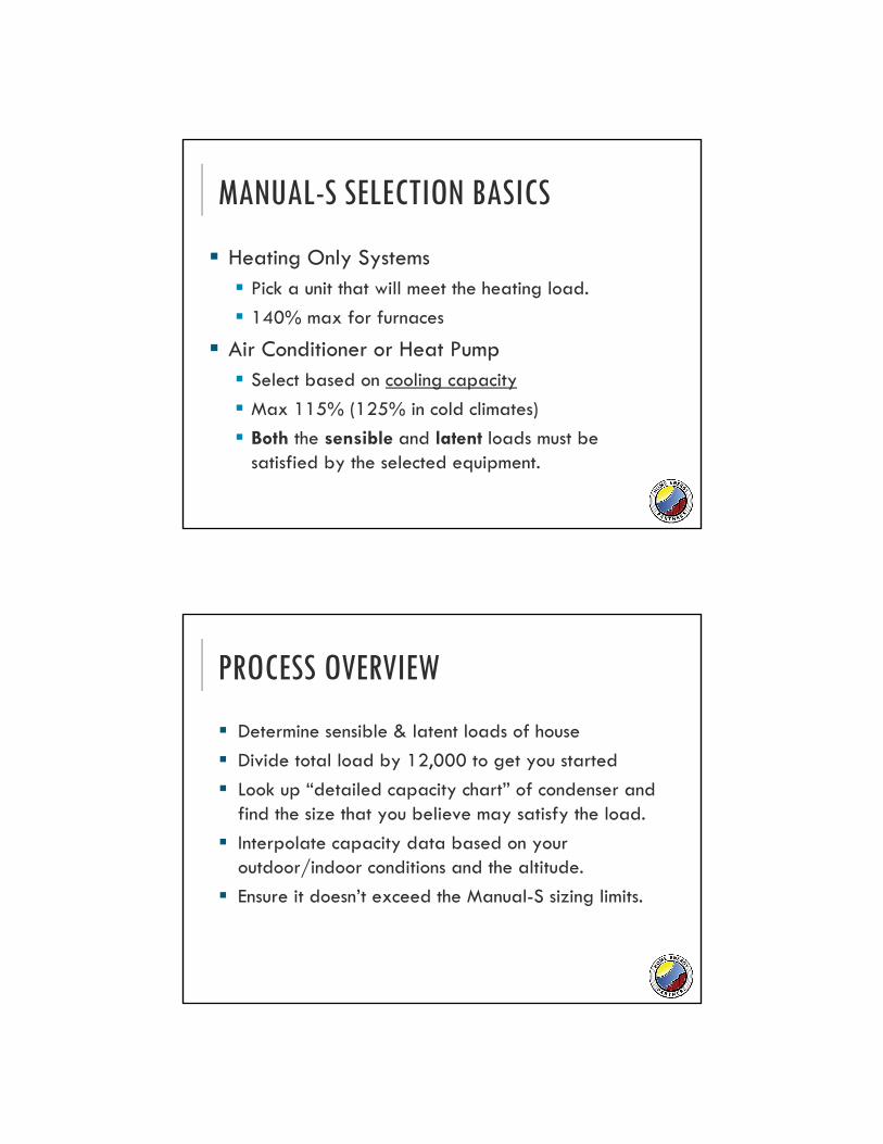
MANUAL-S SELECTION BASICS
Heating Only Systems Pick a unit that will meet the heating load.
140% max for furnaces
Air Conditioner or Heat Pump Select based on cooling capacity
Max 115% (125% in cold climates)
Both the sensible and latent loads must be satisfied by the selected equipment.
PROCESS OVERVIEW
Determine sensible & latent loads of house
Divide total load by 12,000 to get you started
Look up “detailed capacity chart” of condenser and find the size that you believe may satisfy the load.
Interpolate capacity data based on your outdoor/indoor conditions and the altitude.
Ensure it doesn’t exceed the Manual-S sizing limits.
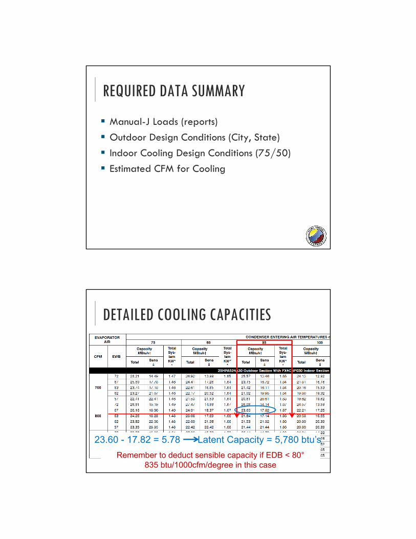
REQUIRED DATA SUMMARY
Manual-J Loads (reports)
Outdoor Design Conditions (City, State)
Indoor Cooling Design Conditions (75/50)
Estimated CFM for Cooling
DETAILED COOLING CAPACITIES
23.60 - 17.82 = 5.78 Latent Capacity = 5,780 btu’s
Remember to deduct sensible capacity if EDB < 80°835 btu/1000cfm/degree in this case
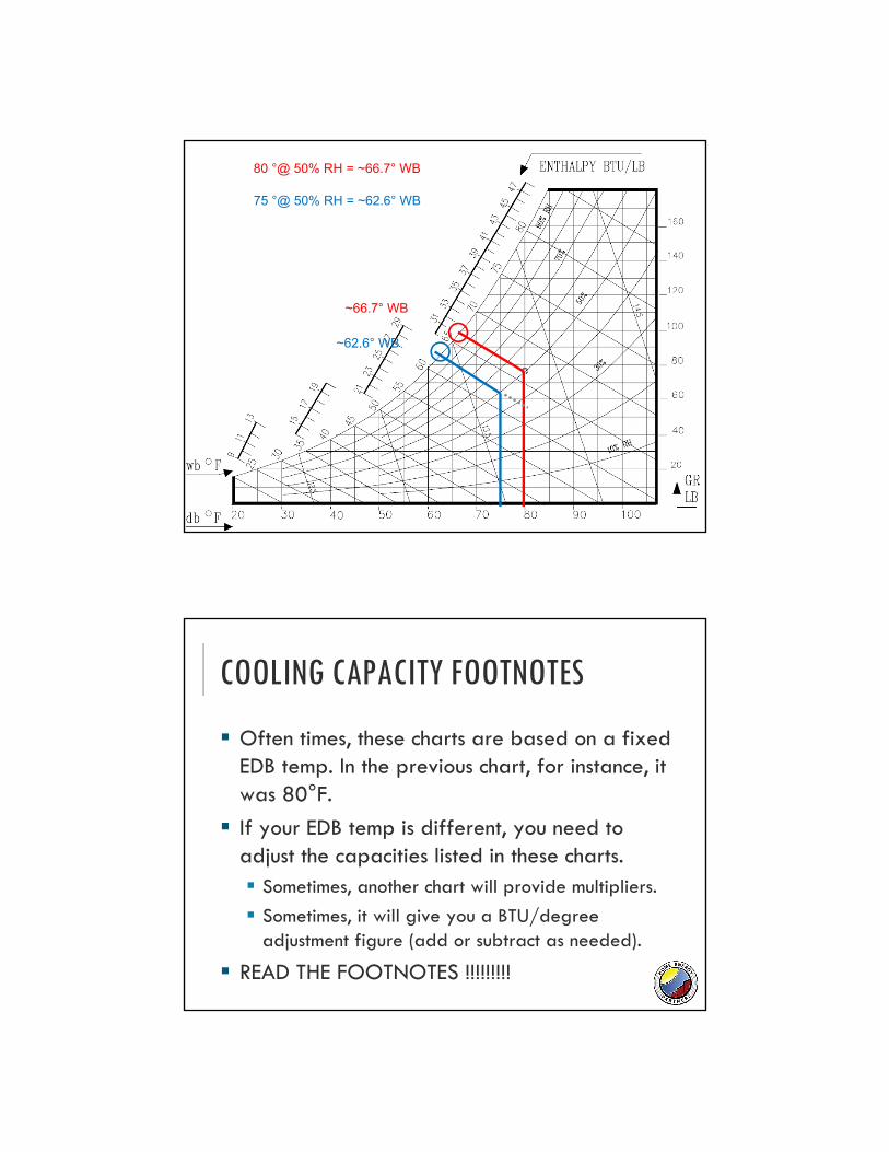
~66.7° WB
~62.6° WB
75 °@ 50% RH = ~62.6° WB
80 °@ 50% RH = ~66.7° WB
COOLING CAPACITY FOOTNOTES
Often times, these charts are based on a fixed EDB temp. In the previous chart, for instance, it was 80°F.
If your EDB temp is different, you need to adjust the capacities listed in these charts. Sometimes, another chart will provide multipliers.
Sometimes, it will give you a BTU/degree adjustment figure (add or subtract as needed).
READ THE FOOTNOTES !!!!!!!!!
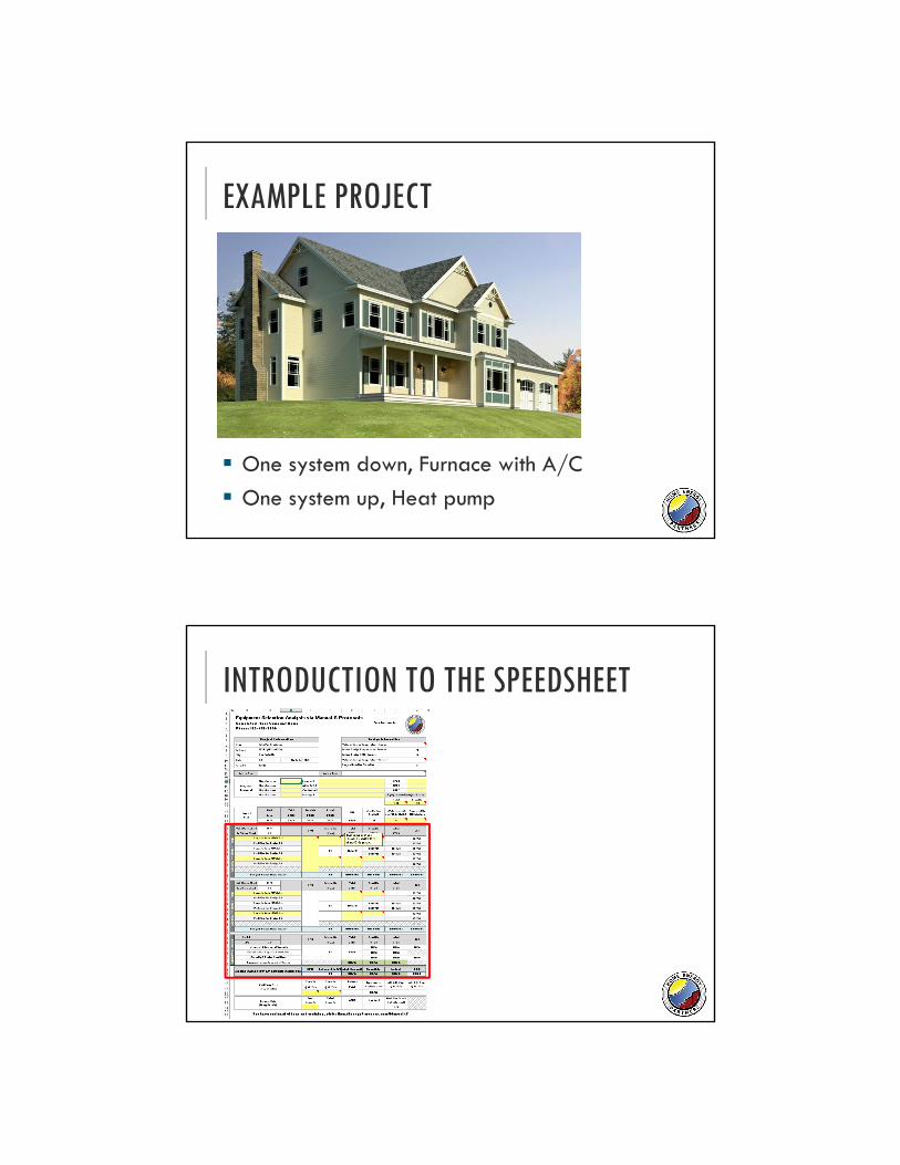
EXAMPLE PROJECT
One system down, Furnace with A/C
One system up, Heat pump
INTRODUCTION TO THE SPEEDSHEET
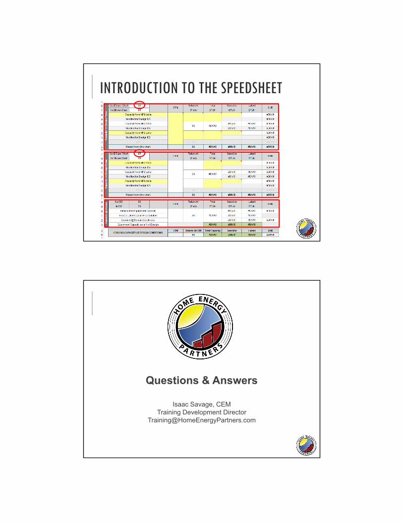
INTRODUCTION TO THE SPEEDSHEET
Questions & Answers
Isaac Savage, CEMTraining Development Director