Embed Size (px)
Citation preview

PIM00012 【INSTRUCTION MANUAL】 1/47
DAIKIN INDUSTRIES, LTD.
Hybrid Hydraulic System “Super Unit”
SUT00D4016 SUT00D6021
Instruction Manual
DAIKIN INDUSTRIES, LTD
油 機 事 業 部
Oil Hydraulics Division
PIM00012 【INSTRUCTION MANUAL】 2/47
DAIKIN INDUSTRIES, LTD.
《SAFETY PRECAUTIONS》 ■Before Usage ・To ensure to notify these contents of this document for user.
・Add this contents to your machine’s handling manual which uses this product. ・Before installation, operation or maintenance, read thoroughly this handling manual and other attached
documents and learn equipments knowledge, safety information and attentions, then use this product properly.
・To ensure keeping this manual, attached documents and supply specifications and so on, whenever user enable read these documents.
・So all figure or photo in this manual are sometimes drawn the state of removing the cover or safety insulate object to explain details, which you operate surely put the cover or insulate object as it was before and operate following this manual.
・ This manual may be changed for improvement of the product or alteration of specifications or improve this manual more easily. As for the hydraulic division internet service (DHCnet Homepage) ( http://www.dhcnet.co.jp:8100/)
・This document is about safety handling of our hydraulic unit. Prepare date for safety handling according to the standard for safety operation or maintenance of your machine.
■Symbols of safety precautions in this manual ・In this manual, safety precautions are represented and classify 3 rank, “ Danger”, “ Warning” and “ Caution”.
Danger: If you ignore this symbol and handle improperly, it may pose a high risk of causing death or serious injury.
Warning: If you ignore this symbol and handle improperly, it may pose the risk of causing death or serious injury.
Caution: If you ignore this symbol and handle improperly, it may pose the potential risk of causing injury or damage to the product or property.
Although the matter is mentioned in “ Caution” symbol, there will cause serious result.
Be sure to observe these precautions. ■Safety ◆ General
Danger
・Qualified people perform the task such as transportation, installation, piping, wiring, operation, handling, maintenance, and inspection.
・When working, make use of protective tools (uniform, safety belt, helmet, safety shoes, gloves, etc). ・Do not use another specifications which is mentioned in the catalog, or delivery specifications.
Caution
・Be sure to enforce daily inspection (it is mentioned in this document, or in attached document.) ・Do not stand, beat or add pressure on the products, or you may be injured and the product is damaged.
PIM00012 【INSTRUCTION MANUAL】 3/47
DAIKIN INDUSTRIES, LTD.
《Exemption Clause》 ・Damages owing to earthquake, fire, and action of the third party, other accidents, intentional or negligence, misuse
of customers, use under unusual conditions we would exempt from any responsibilities.
・Incidental damages (loss of business profit, business suspension) owing to usage of this product, or impossibility of usage, we would exempt from any responsibilities.
・Accidents and damages caused by disobeying manuals or supply specifications, we would exempt from
any responsibilities.
・Damages caused by wrong working owing to combination of connecting equipment, we would exempt from any responsibilities.
《Limitation of uses》 ・Make sure to consider the situation, in case of life threatening owing to breakdown or wrong working of this
machine, or possibilities of danger to the human body.
・Though, this product manufactured under strict quality control, in case of using important equipment, to prevent serious accident or damage from failure of this machine, install safety equipment.
PIM00012 【INSTRUCTION MANUAL】 4/47
DAIKIN INDUSTRIES, LTD.
-Table of contents- 【1. Preface】 ----- 5 【2. Feature and construction】 ----- 5~6 【3. Nomenclature】 ----- 7 【4. Specifications and operating conditions】 ----- 8 【5. Attention to use】 ----- 9 【6. Name of Parts】 ----- 10 【7. Hydraulic circuit】 ----- 11~12 ■ Hydraulic circuit ■ Parts ■ Piping
【8. Points for transporting, moving, and installing】 ----- 13~14 ■ Operating ■ Transporting ■ Installation
【9. Preparation for operation】 ----- 15~20 ■ Electric Wiring ■ Input and output signal specification
【10. Test run】 ----- 21 【11. Operating manual of the control panel】 ----- 22~33 (Main points for setting the rate of flow and the pressure) ■ General description ■ Explanation of each mode ■ Shift to each mode ■ Operation manual of each mode a) Monitor mode b) Set up mode c) Alarm mode ■ The indication list of alarm code
【12. Maintenance】 ----- 34~49 【Attached Document : Points for adjusting the high pressure safety valve】 ----- 40 【Attached Document : Power on and the time chart of the alarm】 ----- 41~46 【Attached Document : Common for the input signal of the external I/O signal】 ----- 47
PIM00012 【INSTRUCTION MANUAL】 5/47
DAIKIN INDUSTRIES, LTD.
【1. Preface】 Thank you for choosing the “SUPER UNIT” series of IPM motor driven hydraulic unit from DAIKIN. IPM motor driven hydraulic unit “SUPER UNIT” realized overwhelming energy-saving and high function by adopting hydraulic technology and the energy-saving IPM motor driven system of our own development. When using “SUPER UNIT: SUT series”, manage proper handling and maintenance after reading this manual thoroughly to cross for a long time and to keep good performance. Approve it in case the contents of this manual are sometimes partly different from the product because of the change of the parts according to the improvement of quality, performance and other circumstances.
【2. Feature and Construction】
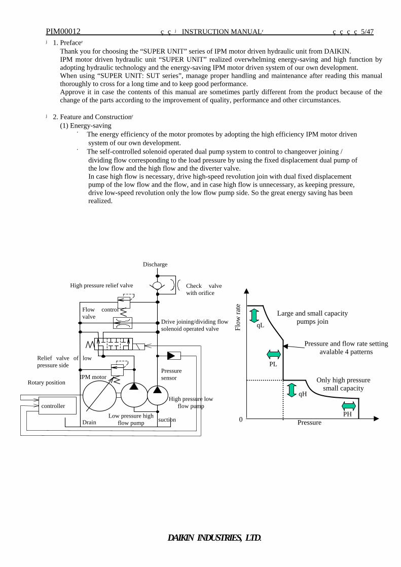
(1) Energy-saving ■ The energy efficiency of the motor promotes by adopting the high efficiency IPM motor driven
system of our own development. ■ The self-controlled solenoid operated dual pump system to control to changeover joining /
dividing flow corresponding to the load pressure by using the fixed displacement dual pump of the low flow and the high flow and the diverter valve. In case high flow is necessary, drive high-speed revolution join with dual fixed displacement pump of the low flow and the flow, and in case high flow is unnecessary, as keeping pressure, drive low-speed revolution only the low flow pump side. So the great energy saving has been realized.
Discharge
Flow controlvalve
Drain
Relief valve of lowpressure side
High pressure relief valve Check valvewith orifice
Drive joining/dividing flowsolenoid operated valve
Pressure sensor
controller
IPM motor
High pressure low flow pump
suction Low pressure high flow pump
Rotary position Only high pressure small capacity
0
Large and small capacity pumps join
Pressure
Flow
rate
PL
PH
qL
qH
Pressure and flow rate settingavalable 4 patterns
PIM00012 【INSTRUCTION MANUAL】 6/47
DAIKIN INDUSTRIES, LTD.
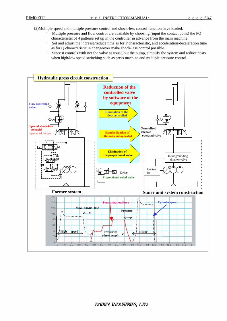
(2)Multiple speed and multiple pressure control and shock-less control function have loaded.
■ Multiple pressure and flow control are available by choosing (input the contact point) the PQ characteristic of 4 patterns set up in the controller in advance from the main machine.
■ Set and adjust the increase/reduce time as for P characteristic, and acceleration/deceleration time as for Q characteristic in changeover make shock-less control possible.
■ Since it controls with not the valve as usual, but the pump, simplify the system and reduce costs when high/low speed switching such as press machine and multiple pressure control.
Hydraulic press circuit construction
Cylinder speed Pressurization force
High speed Rising
Slow down→lowPressure
Pressurize (three stage)
MController
Generalized solenoid operated valve
Joining/dividing diverter valve
DriveM
Special shock-less solenoid operated valve
Flow controlled valve
Proportional relief valve
Standardization of the solenoid operated
Elimination of theflow controlled
Elimination of the proportional valve
Reduction of the controlled valve
by software of the equipment
Super unit system constructionFormer system
PIM00012 【INSTRUCTION MANUAL】 7/47
DAIKIN INDUSTRIES, LTD.
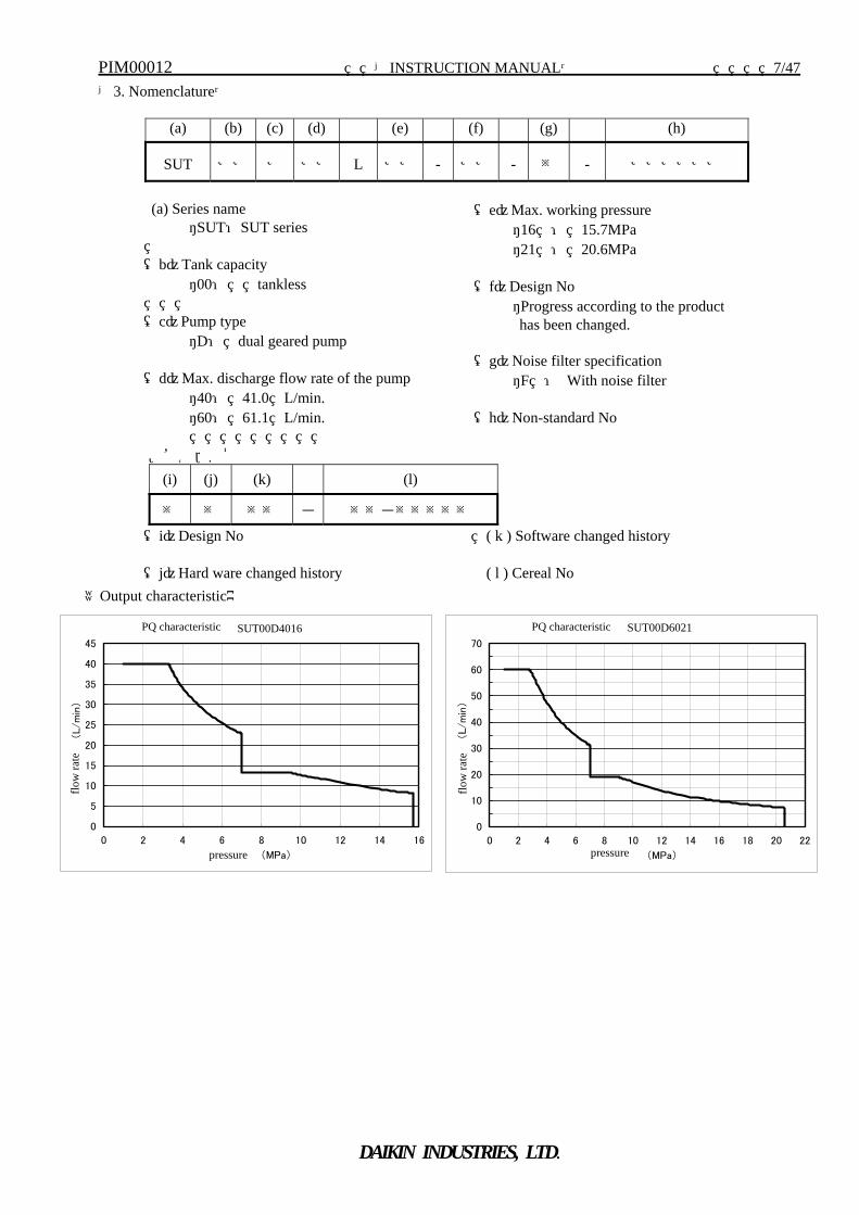
【3. Nomenclature】
(a) (b) (c) (d) (e) (f) (g) (h)
SUT ※※ ※ ※※ L ※※ - ※※ - ※ - ※※※※※※
(a) Series name
・SUT:SUT series (b)Tank capacity
・00: tankless (c)Pump type
・D: dual geared pump
(d)Max. discharge flow rate of the pump ・40: 41.0 L/min. ・60: 61.1 L/min.
(e)Max. working pressure ・16 : 15.7MPa ・21 : 20.6MPa
(f)Design No ・Progress according to the product
has been changed. (g)Noise filter specification
・F : With noise filter (h)Non-standard No
MFG.No (i) (j) (k) (l)
※ ※ ※※ - ※※-※※※※※
(i)Design No ( k ) Software changed history (j)Hard ware changed history ( l ) Cereal No
《Output characteristic》
P-Q特性 (SUT**D40L16-10-*****-*)
0
5
10
15
20
25
30
35
40
45
0 2 4 6 8 10 12 14 16
圧力 (MPa)
流量
(L/m
in)
P-Q特性 (SUT**D60L21-10-*****-*)
0
10
20
30
40
50
60
70
0 2 4 6 8 10 12 14 16 18 20 22
圧力 (MPa)
流量
(L/m
in)
flow
rate
PQ characteristic PQ characteristic
pressure pressure
SUT00D4016 SUT00D6021
flow
rate
PIM00012 【INSTRUCTION MANUAL】 8/47
DAIKIN INDUSTRIES, LTD.
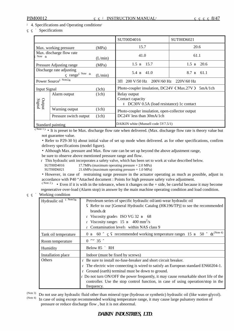
【4. Specifications and Operating conditions】 ■Specifications
(Note 1)・It is preset to be Max. discharge flow rate when delivered. (Max. discharge flow rate is theory value but not guarantee value. ・Refer to P29-30 b) about initial value of set up mode when delivered. as for other specifications, confirm delivery specifications (model figure). ・Although Max. pressure and Max. flow rate can be set up beyond the above adjustment range, be sure to observe above mentioned pressure range and flow. ・This hydraulic unit incorporates a safety valve, which has been set to work at value described below. SUT00D4016 17.7MPa (maximum operating pressure + 2.0 MPa) SUT00D6021 21.6MPa (maximum operating pressure + 1.0 MPa) ・However, in case of restraining surge pressure in the actuator operating as much as possible, adjust in accordance with P40 “Attached document : Points for high pressure safety valve adjustment. (Note 2) ・Even if it is with in the tolerance, when it changes on the + side, be careful because it may become regenerative over-load (Alarm stop) in answer by the main machine operating condition and load condition.
■Working condition
(Note 3) Do not use any hydraulic fluid other than mineral type (hydrous or synthetic) hydraulic oil (like water-glycol). (Note 4) In case of using except recommended working temperature range, it may cause large pulsatory motion of
pressure or reduce discharge flow , but it is not abnormal.
SUT00D4016 SUT00D6021
Max. working pressure (MPa) 15.7 20.6 Max. discharge flow rate (Note1) (L/min) 41.0 61.1
Pressure Adjusting range (MPa) 1.5 ~ 15.7 1.5 ~ 20.6 Discharge rate adjusting
range(Note1) (L/min) 5.4 ~ 41.0 8.7 ~ 61.1
Power Source(Note2) 3φ 200 V/50 Hz 200V/60 Hz 220V/60 Hz
Input Signal (3ch) Photo-coupler insulation, DC24V(Max.27V) 5mA/1ch Alarm output (1ch) Relay output
Contact capacity : DC30V 0.5A (load resistance) 1c contact
Warning output (1ch)
Output
Signal
Pressure switch output (1ch) Photo-coupler insulation, open-collector output DC24V less than 30mA/1ch
Standard painting DAIKIN white (Munsell code 5Y7.5/1)
Hydraulic oil (Note3) Petroleum series of specific hydraulic oil/anti-wear hydraulic oil (Refer to our [General Hydraulic Catalog (HK196/TP)] to see the recommended
brands.) ・Viscosity grade:ISO VG 32 ~ 68 ・Viscosity range:15 ~ 400 mm2/s ・Contamination level:within NAS class 9
Tank oil temperature 0 ~ 60 ℃ (recommended working temperature range:15 ~ 50 ℃)(Note 4)
Room temperature 0 ~ 35 ℃
Humidity Below 85 %RH
Installation place Indoor (must be fixed by screws) Others ・Be sure to install no-fuse-breaker and short circuit breaker.
・The electric wire connecting is wired to satisfy an European standard EN60204-1.・Ground (earth) terminal must be down to ground. ・Do not turn ON/OFF the power frequently, it may cause remarkable short life of the
controller. Use the stop control function, in case of using operation/stop in the frequency.
PIM00012 【INSTRUCTION MANUAL】 9/47
DAIKIN INDUSTRIES, LTD.
【5.Attention point in use】
(1) To get the saving-energy features effectively, “Super unit” has solenoid valve to divide and connect the flow of double pump. In case that the operation point of the machine is near to the switching point of this solenoid valve, performance would be unstable. In this case, flow or pressure rates need to be adjusted. Moreover, so the system sets Hysterisis rate to avoid unstable situation, flow or pressure also need to be adjusted in case the operating point is near to the rate.
(2) The “Super unit” is installed to the motor pump with vibration absorbing rubber so that the vibration of the motor pump may not be effected to the unit. Since the discharge piping port is mounted free, be sure to pipe not to hit the cover even if the discharge pipe shakes with the anti-power such as the hose. As the piping to the unit, it is better to use hose connection.
(3) The “Super unit” is equipped a AC fan motor to cool off the operation oil and the motor. Do not put an obstacle within 10cm from inhalation and exhaust side of the AC fan motor because of its ventilation.
(4) The “Super unit” builds in the check valve with orifice on the discharge line. In case quick response is required to the pressure relief of the machine, the pressure relief circuit is necessary to provide separately. In addition to it, it is not trouble though oil flow noise is sometimes occurred from this orifice at stopping in case of large load volume.
(5) The “Super unit” is adopted IPM motor, and reverse electric power occurs at the time of the diverting operation (regenerative operation). When switching of the high frequency on the operation condition that it is easy to cause reverse electric power becomes regenerative over-load, and then it may cause the unit stop.
(6) The “Super unit” equipped with relief valve. Though this relief valve is set up the regular pressure when
delivered, the long repetition operation of the equipment and contaminant in the hydraulic oil may decrease the setup pressure of the high pressure relief valve. In this case, re-adjust the setup pressure of the high pressure relief valve according to that valve setup value (another document).
In order to suppress surge pressure to protect the master machine peripheral equipment (actuator, pressure gauge, etc.), it is recommended that the pressure setting should be set lower than safety valve setting 2.0Mpa for SUT00D4016, and 1.0 MPa for SUT00D6021.
PIM00012 【INSTRUCTION MANUAL】 10/47
DAIKIN INDUSTRIES, LTD.
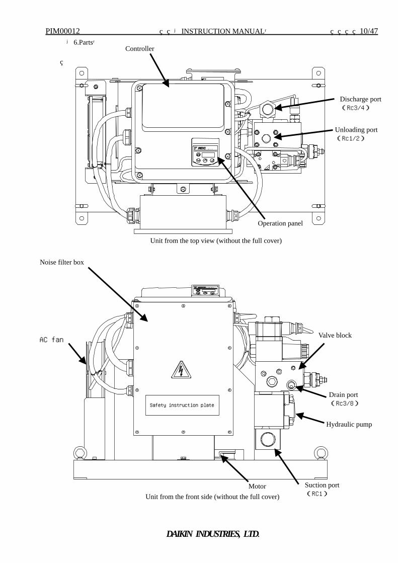
【6.Parts】
Safety instruction plate
Controller
AC fan
Hydraulic pump
Motor
Operation panel
Unit from the top view (without the full cover)
Unit from the front side (without the full cover)
Valve block
Discharge port (Rc3/4)
Unloading port (Rc1/2)
Drain port (Rc3/8)
Suction port (RC1)
Noise filter box
PIM00012 【INSTRUCTION MANUAL】 11/47
DAIKIN INDUSTRIES, LTD.
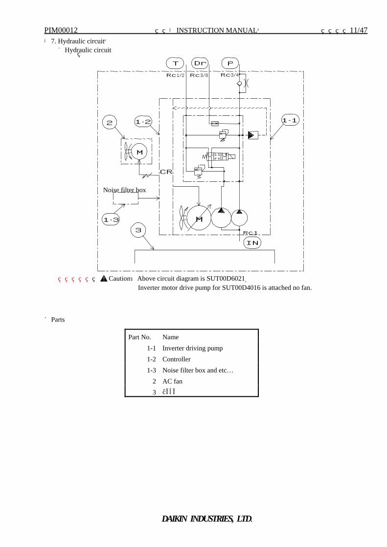
【7. Hydraulic circuit】 ■Hydraulic circuit
Caution:Above circuit diagram is SUT00D6021. Inverter motor drive pump for SUT00D4016 is attached no fan.
■Parts
Part No. Name 1-1 Inverter driving pump 1-2 Controller 1-3 Noise filter box and etc…
2 AC fan 3 Base
1-3
3
Noise filter box
M
M
IN
1-1 1-2 2
T Dr P
Rc1/2 Rc3/8 Rc3/4
Rc1
CR
PIM00012 【INSTRUCTION MANUAL】 12/47
DAIKIN INDUSTRIES, LTD.
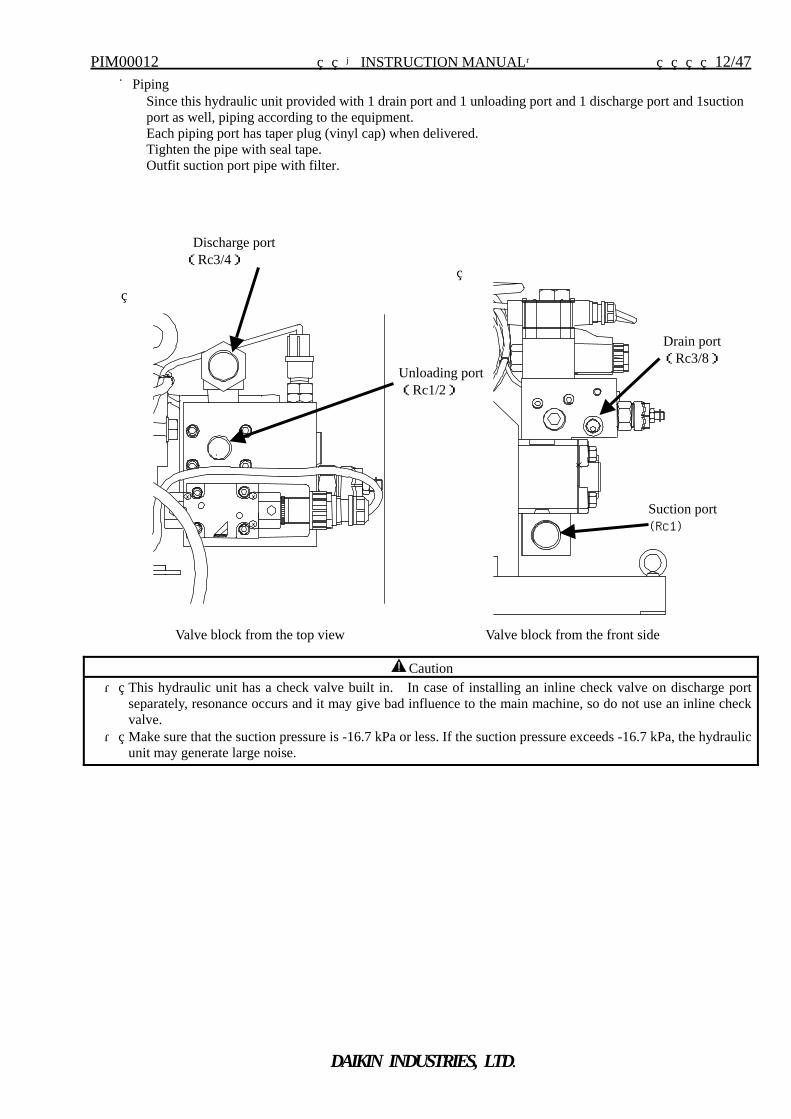
■Piping Since this hydraulic unit provided with 1 drain port and 1 unloading port and 1 discharge port and 1suction port as well, piping according to the equipment. Each piping port has taper plug (vinyl cap) when delivered. Tighten the pipe with seal tape. Outfit suction port pipe with filter.
Caution ・ This hydraulic unit has a check valve built in. In case of installing an inline check valve on discharge port
separately, resonance occurs and it may give bad influence to the main machine, so do not use an inline check valve.
・ Make sure that the suction pressure is -16.7 kPa or less. If the suction pressure exceeds -16.7 kPa, the hydraulic unit may generate large noise.
Discharge port (Rc3/4)
Drain port(Rc3/8)
Suction port (Rc1)
Unloading port (Rc1/2)
Valve block from the top view Valve block from the front side
PIM00012 【INSTRUCTION MANUAL】 13/47
DAIKIN INDUSTRIES, LTD.
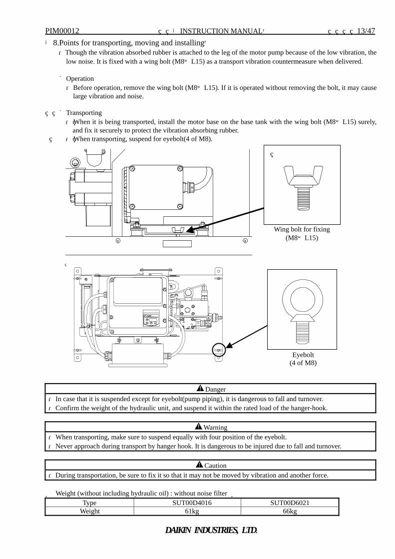
【8.Points for transporting, moving and installing】 ・Though the vibration absorbed rubber is attached to the leg of the motor pump because of the low vibration, the
low noise. It is fixed with a wing bolt (M8×L15) as a transport vibration countermeasure when delivered. ■Operation ・Before operation, remove the wing bolt (M8×L15). If it is operated without removing the bolt, it may cause
large vibration and noise.
■Transporting ・ When it is being transported, install the motor base on the base tank with the wing bolt (M8×L15) surely,
and fix it securely to protect the vibration absorbing rubber. ・ When transporting, suspend for eyebolt(4 of M8).
Danger ・In case that it is suspended except for eyebolt(pump piping), it is dangerous to fall and turnover. ・Confirm the weight of the hydraulic unit, and suspend it within the rated load of the hanger-hook.
Warning
・When transporting, make sure to suspend equally with four position of the eyebolt. ・Never approach during transport by hanger hook. It is dangerous to be injured due to fall and turnover.
Caution
・During transportation, be sure to fix it so that it may not be moved by vibration and another force. ≪ Weight (without including hydraulic oil) : without noise filter ≫
Type SUT00D4016 SUT00D6021 Weight 61kg 66kg
Wing bolt for fixing(M8×L15)
Eyebolt (4 of M8)
PIM00012 【INSTRUCTION MANUAL】 14/47
DAIKIN INDUSTRIES, LTD.
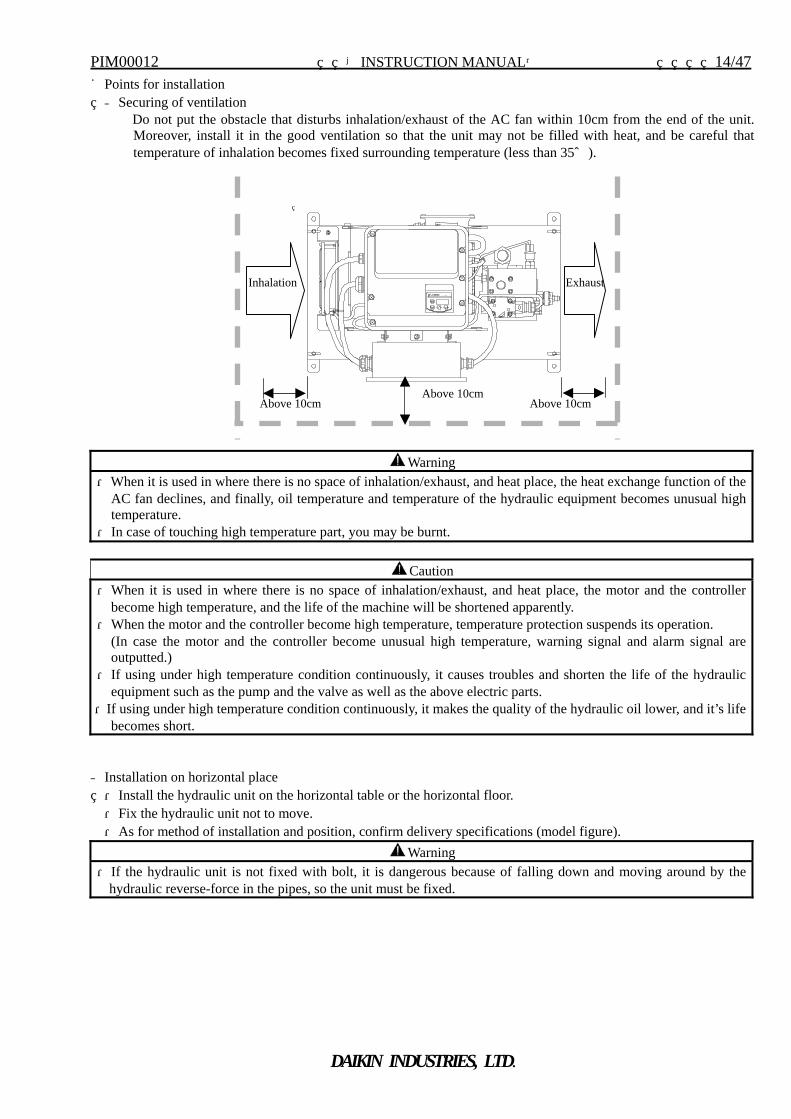
■Points for installation ◆Securing of ventilation
Do not put the obstacle that disturbs inhalation/exhaust of the AC fan within 10cm from the end of the unit. Moreover, install it in the good ventilation so that the unit may not be filled with heat, and be careful that temperature of inhalation becomes fixed surrounding temperature (less than 35℃).
Warning
・When it is used in where there is no space of inhalation/exhaust, and heat place, the heat exchange function of the AC fan declines, and finally, oil temperature and temperature of the hydraulic equipment becomes unusual high temperature.
・In case of touching high temperature part, you may be burnt.
◆Installation on horizontal place ・Install the hydraulic unit on the horizontal table or the horizontal floor. ・Fix the hydraulic unit not to move. ・As for method of installation and position, confirm delivery specifications (model figure).
Warning ・If the hydraulic unit is not fixed with bolt, it is dangerous because of falling down and moving around by the
hydraulic reverse-force in the pipes, so the unit must be fixed.
Caution ・When it is used in where there is no space of inhalation/exhaust, and heat place, the motor and the controller
become high temperature, and the life of the machine will be shortened apparently. ・When the motor and the controller become high temperature, temperature protection suspends its operation.
(In case the motor and the controller become unusual high temperature, warning signal and alarm signal are outputted.)
・If using under high temperature condition continuously, it causes troubles and shorten the life of the hydraulic equipment such as the pump and the valve as well as the above electric parts.
・If using under high temperature condition continuously, it makes the quality of the hydraulic oil lower, and it’s life becomes short.
Exhaust
Above 10cm Above 10cm
Inhalation
Above 10cm
PIM00012 【INSTRUCTION MANUAL】 15/47
DAIKIN INDUSTRIES, LTD.
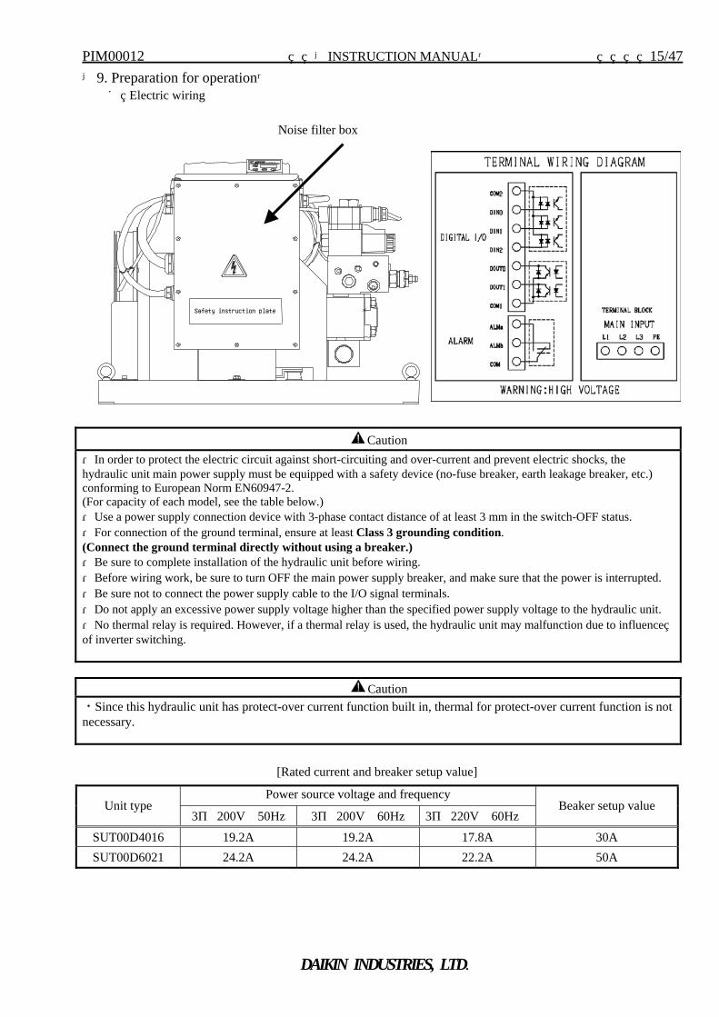
【9. Preparation for operation】 ■ Electric wiring
Caution ・Since this hydraulic unit has protect-over current function built in, thermal for protect-over current function is not necessary.
[Rated current and breaker setup value]
Power source voltage and frequency Unit type
3φ 200V 50Hz 3φ 200V 60Hz 3φ 220V 60Hz Beaker setup value
SUT00D4016 19.2A 19.2A 17.8A 30A SUT00D6021 24.2A 24.2A 22.2A 50A
Caution
・In order to protect the electric circuit against short-circuiting and over-current and prevent electric shocks, the hydraulic unit main power supply must be equipped with a safety device (no-fuse breaker, earth leakage breaker, etc.) conforming to European Norm EN60947-2. (For capacity of each model, see the table below.) ・Use a power supply connection device with 3-phase contact distance of at least 3 mm in the switch-OFF status. ・For connection of the ground terminal, ensure at least Class 3 grounding condition. (Connect the ground terminal directly without using a breaker.) ・Be sure to complete installation of the hydraulic unit before wiring. ・Before wiring work, be sure to turn OFF the main power supply breaker, and make sure that the power is interrupted. ・Be sure not to connect the power supply cable to the I/O signal terminals. ・Do not apply an excessive power supply voltage higher than the specified power supply voltage to the hydraulic unit. ・No thermal relay is required. However, if a thermal relay is used, the hydraulic unit may malfunction due to influence of inverter switching.
Safety instruction plate
Noise filter box
PIM00012 【INSTRUCTION MANUAL】 16/47
DAIKIN INDUSTRIES, LTD.
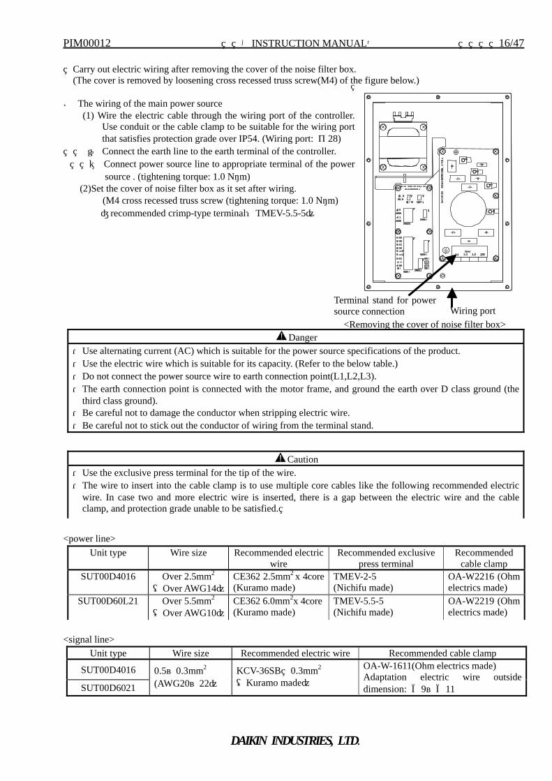
Terminal stand for powersource connection
<Removing the cover of noise filter box> Wiring port
Carry out electric wiring after removing the cover of the noise filter box. (The cover is removed by loosening cross recessed truss screw(M4) of the figure below.) ● The wiring of the main power source
(1) Wire the electric cable through the wiring port of the controller. Use conduit or the cable clamp to be suitable for the wiring port that satisfies protection grade over IP54. (Wiring port: φ28)
① Connect the earth line to the earth terminal of the controller. ② Connect power source line to appropriate terminal of the power
source . (tightening torque: 1.0 N・m) (2)Set the cover of noise filter box as it set after wiring.
(M4 cross recessed truss screw (tightening torque: 1.0 N・m) 〔recommended crimp-type terminal:TMEV-5.5-5〕
<power line> <signal line>
Danger ・Use alternating current (AC) which is suitable for the power source specifications of the product. ・Use the electric wire which is suitable for its capacity. (Refer to the below table.) ・Do not connect the power source wire to earth connection point(L1,L2,L3). ・The earth connection point is connected with the motor frame, and ground the earth over D class ground (the
third class ground). ・Be careful not to damage the conductor when stripping electric wire. ・Be careful not to stick out the conductor of wiring from the terminal stand.
Caution ・Use the exclusive press terminal for the tip of the wire. ・The wire to insert into the cable clamp is to use multiple core cables like the following recommended electric
wire. In case two and more electric wire is inserted, there is a gap between the electric wire and the cable clamp, and protection grade unable to be satisfied.
Unit type Wire size Recommended electric wire
Recommended exclusive press terminal
Recommended cable clamp
SUT00D4016
Over 2.5mm2 (Over AWG14)
CE362 2.5mm2 x 4core (Kuramo made)
TMEV-2-5 (Nichifu made)
OA-W2216 (Ohm electrics made)
SUT00D60L21
Over 5.5mm2 (Over AWG10)
CE362 6.0mm2x 4core(Kuramo made)
TMEV-5.5-5 (Nichifu made)
OA-W2219 (Ohm electrics made)
Unit type Wire size Recommended electric wire Recommended cable clamp
SUT00D4016
SUT00D6021
0.5~0.3mm2 (AWG20~22)
KCV-36SB 0.3mm2 (Kuramo made)
OA-W-1611(Ohm electrics made) Adaptation electric wire outside dimension: Φ9~Φ11
PIM00012 【INSTRUCTION MANUAL】 17/47
DAIKIN INDUSTRIES, LTD.
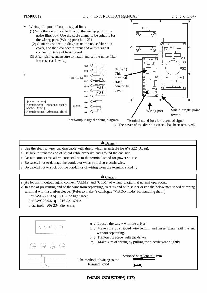
● Wiring of input and output signal lines (1) Wire the electric cable through the wiring port of the
noise filter box. Use the cable clamp to be suitable for the wiring port. (Wiring port: hole 21)
(2) Confirm connection diagram on the noise filter box cover, and then connect to input and output signal connection table of basic board.
(3) After wiring, make sure to install and set the noise filter box cover as it was.
[COM-ALMa] Normal: closed Abnormal: opened [COM-ALMb] Normal: opened Abnormal: closed
① Loosen the screw with the driver. ② Make sure of stripped wire length, and insert them until the end
without separating. ③ Tighten the screw with the driver ④ Make sure of wiring by pulling the electric wire slightly
The method of wiring to the terminal stand 6
Stripped wire length: 6mm
Wiring port
(Note.1)This terminal stand cannot beused.
《The cover of the distribution box has been removed》Terminal stand for alarm/control signal
Danger ・Use the electric wire, cab-tire cable with shield which is suitable for AWG22 (0.3sq). ・Be sure to treat the end of shield cable properly, and ground the one side. ・Do not connect the alarm connect line to the terminal stand for power source. ・Be careful not to damage the conductor when stripping electric wire. ・Be careful not to stick out the conductor of wiring from the terminal stand.
Caution ・As for alarm output signal connect “ALMa” and “COM” of wiring diagram at normal operation. ・In case of preventing end of the wire from separating, treat its end with solder or use the below mentioned crimping
terminal with insulation sleeve. (Refer to maker’s catalogue “WAGO made” for handling them.) For AWG22 0.3 sq: 216-322 light green
For AWG20 0.5 sq: 216-221 white Press tool: 206-204 Bio- crimp
Input/output signal wiring diagram
Shield single pointground
PIM00012 【INSTRUCTION MANUAL】 18/47
DAIKIN INDUSTRIES, LTD.
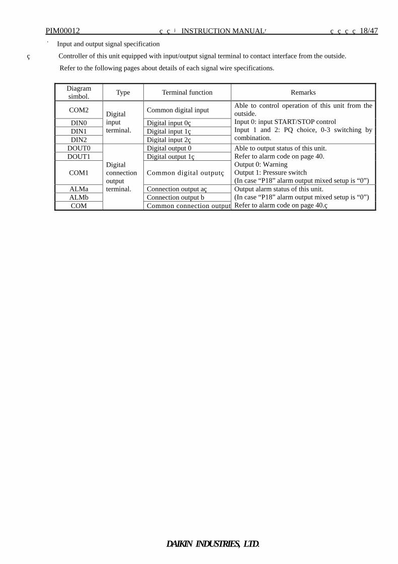
■ Input and output signal specification
Controller of this unit equipped with input/output signal terminal to contact interface from the outside.
Refer to the following pages about details of each signal wire specifications.
Diagram simbol. Type Terminal function Remarks
COM2 Common digital input
DIN0 Digital input 0 DIN1 Digital input 1 DIN2
Digital input terminal.
Digital input 2
Able to control operation of this unit from the outside. Input 0: input START/STOP control Input 1 and 2: PQ choice, 0-3 switching by combination.
DOUT0 Digital output 0 DOUT1 Digital output 1
COM1 Common digital output
Able to output status of this unit. Refer to alarm code on page 40. Output 0: Warning Output 1: Pressure switch (In case “P18” alarm output mixed setup is “0”)
ALMa Connection output a ALMb Connection output b COM
Digital connection output terminal.
Common connection output
Output alarm status of this unit. (In case “P18” alarm output mixed setup is “0”) Refer to alarm code on page 40.
PIM00012 【INSTRUCTION MANUAL】 19/47
DAIKIN INDUSTRIES, LTD.
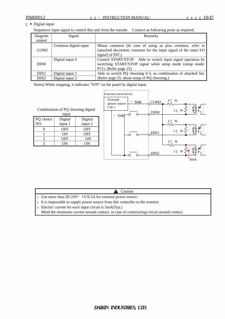
◆Digital input. Sequencer input signal to control this unit from the outside. Connect as following point as required.
Notes) While stopping, it indicates “STP” on the panel by digital input.
External control device
DIN2
4.7kΩ
2.2kΩ
4.7kΩ
2.2kΩ
4.7kΩ
2.2kΩ
COM2
DIN0
DIN1
External power source
( 24v )
5mA
-Side
+SideCombination of PQ choosing digital
input PQ choice NO.
Digital input 1
Digital input 2
0 OFF OFF 1 ON OFF 2 OFF ON 3 ON ON
Diagram simbol
Signal Remarks
COM2 Common digital input Minus common (In case of using as plus common, refer to
[attached document: common for the input signal of the outer I/O signal] of P47.)
DIN0 Digital input 0 Control START/STOP. Able to switch input signal operation by
switching START/STOP signal while setup mode (setup mode: P11). (Refer page 25)
DIN1 Digital input 1 DIN2 Digital input 2
Able to switch PQ choosing 0-3, as combination of attached list. (Refer page 25, about setup of PQ choosing.)
Caution ・Use more than DC24V±1V/0.5A for external power source. ・It is impossible to supply power source from this controller to the exterior. ・Electric current for each input circuit is 5mA(Typ.)
Mind the minimum current around contact, in case of constructing circuit around contact.
PIM00012 【INSTRUCTION MANUAL】 20/47
DAIKIN INDUSTRIES, LTD.
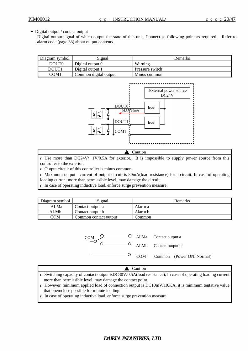
◆Digital output / contact output
Digital output signal of which output the state of this unit. Connect as following point as required. Refer to alarm code (page 33) about output contents.
Diagram symbol. Signal Remarks DOUT0 Digital output 0 Warning DOUT1 Digital output 1 Pressure switch COM1 Common digital output Minus common
Caution ・Use more than DC24V±1V/0.5A for exterior. It is impossible to supply power source from this controller to the exterior. ・Output circuit of this controller is minus common. ・Maximum output current of output circuit is 30mA(load resistance) for a circuit. In case of operating loading current more than permissible level, may damage the circuit. ・In case of operating inductive load, enforce surge prevention measure.
DOUT0
DOUT1
COM1
MAX 30mA
External power source DC24V
load
load
COM Common (Power ON: Normal)
ALMb Contact output b
ALMa Contact output a COM
Diagram symbol Signal Remarks ALMa Contact output a Alarm a
ALMb Contact output b Alarm b COM Common contact output Common
Caution ・Switching capacity of contact output isDC30V/0.5A(load resistance). In case of operating loading current
more than permissible level, may damage the contact point. ・However, minimum applied load of connection output is DC10mV/10μA, it is minimum tentative value
that open/close possible for minute loading. ・In case of operating inductive load, enforce surge prevention measure.
PIM00012 【INSTRUCTION MANUAL】 21/47
DAIKIN INDUSTRIES, LTD.
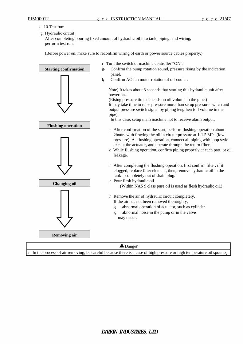
【10.Test run】 ■ Hydraulic circuit
After completing pouring fixed amount of hydraulic oil into tank, piping, and wiring, perform test run. (Before power on, make sure to reconfirm wiring of earth or power source cables properly.)
・Turn the switch of machine controller “ON”. ① Confirm the pump rotation sound, pressure rising by the indication
panel. ② Confirm AC fan motor rotation of oil-cooler.
Note) It takes about 3 seconds that starting this hydraulic unit after power on. (Rising pressure time depends on oil volume in the pipe.) It may take time to raise pressure more than setup pressure switch and output pressure switch signal by piping lengthen (oil volume in the pipe). In this case, setup main machine not to receive alarm output.
・After confirmation of the start, perform flushing operation about
2hours with flowing the oil in circuit pressure at 1-1.5 MPa (low pressure). As flushing operation, connect all piping with loop style except the actuator, and operate through the return filter.
・While flushing operation, confirm piping properly at each part, or oil leakage.
・After completing the flushing operation, first confirm filter, if it
clogged, replace filter element, then, remove hydraulic oil in the tank completely out of drain plug.
・Pour flesh hydraulic oil. (Within NAS 9 class pure oil is used as flesh hydraulic oil.)
・Remove the air of hydraulic circuit completely.
If the air has not been removed thoroughly, ① abnormal operation of actuator, such as cylinder ② abnormal noise in the pump or in the valve
may occur.
Danger ・In the process of air removing, be careful because there is a case of high pressure or high temperature oil spouts.
Starting confirmation
Flushing operation
Changing oil
Removing air
PIM00012 【INSTRUCTION MANUAL】 22/47
DAIKIN INDUSTRIES, LTD.
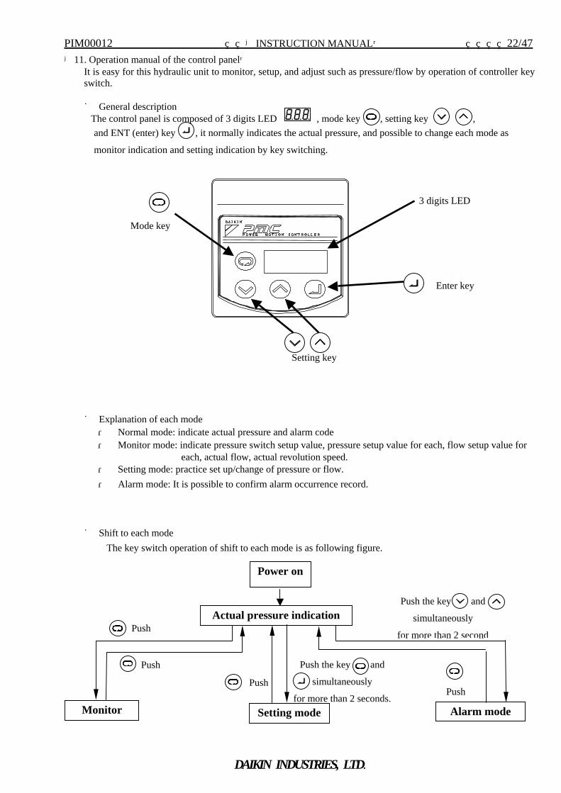
【11. Operation manual of the control panel】 It is easy for this hydraulic unit to monitor, setup, and adjust such as pressure/flow by operation of controller key switch. ■ General description
The control panel is composed of 3 digits LED , mode key , setting key , and ENT (enter) key , it normally indicates the actual pressure, and possible to change each mode as
monitor indication and setting indication by key switching.
■ Explanation of each mode ・ Normal mode: indicate actual pressure and alarm code ・ Monitor mode: indicate pressure switch setup value, pressure setup value for each, flow setup value for
each, actual flow, actual revolution speed. ・ Setting mode: practice set up/change of pressure or flow. ・ Alarm mode: It is possible to confirm alarm occurrence record.
■ Shift to each mode
The key switch operation of shift to each mode is as following figure.
3 digits LED
Enter key
Power on
Actual pressure indication
Monitor Setting mode
Push
Push
Push
Push the key and
simultaneously
for more than 2 seconds.Alarm mode
Push the key and
simultaneously
for more than 2 second
Push
Setting key
Mode key
PIM00012 【INSTRUCTION MANUAL】 23/47
DAIKIN INDUSTRIES, LTD.
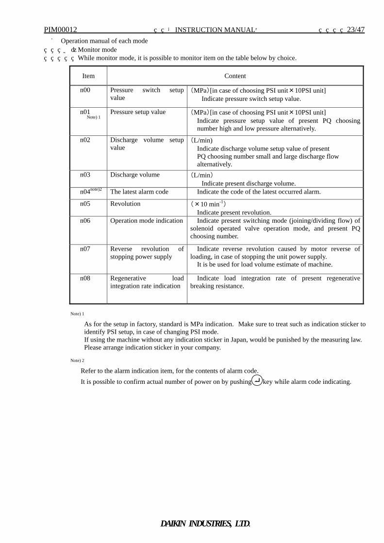
■ Operation manual of each mode a)Monitor mode While monitor mode, it is possible to monitor item on the table below by choice.
Item Content
n00 Pressure switch setup value
(MPa)[in case of choosing PSI unit×10PSI unit] Indicate pressure switch setup value.
n01
Note) 1 Pressure setup value (MPa)[in case of choosing PSI unit×10PSI unit]
Indicate pressure setup value of present PQ choosing number high and low pressure alternatively.
n02 Discharge volume setup value
(L/min) Indicate discharge volume setup value of present PQ choosing number small and large discharge flow alternatively.
n03 Discharge volume (L/min) Indicate present discharge volume.
n04note)2 The latest alarm code Indicate the code of the latest occurred alarm.
n05 Revolution (×10 min-1) Indicate present revolution.
n06 Operation mode indication Indicate present switching mode (joining/dividing flow) of solenoid operated valve operation mode, and present PQ choosing number.
n07 Reverse revolution of stopping power supply
Indicate reverse revolution caused by motor reverse of loading, in case of stopping the unit power supply.
It is be used for load volume estimate of machine.
n08 Regenerative load integration rate indication
Indicate load integration rate of present regenerative breaking resistance.
Note) 1 As for the setup in factory, standard is MPa indication. Make sure to treat such as indication sticker to
identify PSI setup, in case of changing PSI mode. If using the machine without any indication sticker in Japan, would be punished by the measuring law.
Please arrange indication sticker in your company.
Note) 2 Refer to the alarm indication item, for the contents of alarm code. It is possible to confirm actual number of power on by pushing key while alarm code indicating.
PIM00012 【INSTRUCTION MANUAL】 24/47
DAIKIN INDUSTRIES, LTD.
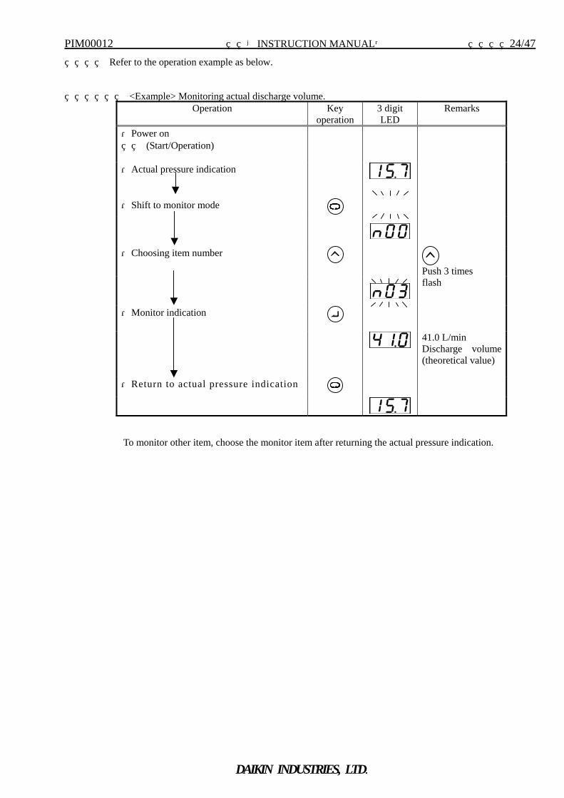
Refer to the operation example as below.
<Example> Monitoring actual discharge volume.
Operation Key operation
3 digit LED
Remarks
・Power on (Start/Operation)
・Actual pressure indication
・Shift to monitor mode
・Choosing item number
Push 3 times
flash
・Monitor indication
41.0 L/min Discharge volume (theoretical value)
・Return to actual pressure indication
To monitor other item, choose the monitor item after returning the actual pressure indication.
PIM00012 【INSTRUCTION MANUAL】 25/47
DAIKIN INDUSTRIES, LTD.
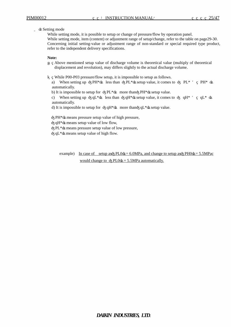
b)Setting mode
While setting mode, it is possible to setup or change of pressure/flow by operation panel. While setting mode, item (content) or adjustment range of setup/change, refer to the table on page29-30. Concerning initial setting-value or adjustment range of non-standard or special required type product, refer to the independent delivery specifications. Note: ① Above mentioned setup value of discharge volume is theoretical value (multiply of theoretical
displacement and revolution), may differs slightly to the actual discharge volume. ② While P00-P03 pressure/flow setup, it is impossible to setup as follows.
a) When setting up 〔PH*〕 less than 〔PL*〕setup value, it comes to 〔 PL* = PH* 〕automatically. b) It is impossible to setup for 〔PL*〕 more than〔PH*〕setup value. c) When setting up 〔qL*〕 less than 〔qH*〕setup value, it comes to 〔 qH* = qL* 〕automatically. d) It is impossible to setup for 〔qH*〕 more than〔qL*〕setup value.
〔PH*〕means pressure setup value of high pressure, 〔qH*〕means setup value of low flow, 〔PL*〕means pressure setup value of low pressure, 〔qL*〕means setup value of high flow.
example) In case of setup as〔PL0〕= 6.0MPa, and change to setup as〔PH0〕= 5.5MPa
would change to 〔PL0〕= 5.5MPa automatically.
PIM00012 【INSTRUCTION MANUAL】 26/47
DAIKIN INDUSTRIES, LTD.
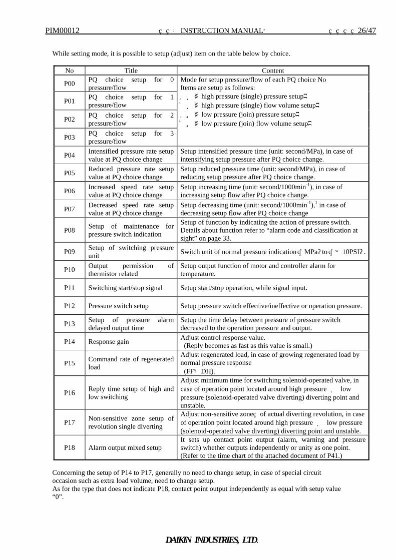
While setting mode, it is possible to setup (adjust) item on the table below by choice.
No Title Content
P00 PQ choice setup for 0 pressure/flow
P01 PQ choice setup for 1 pressure/flow
P02 PQ choice setup for 2 pressure/flow
P03 PQ choice setup for 3 pressure/flow
Mode for setup pressure/flow of each PQ choice No Items are setup as follows: PH《high pressure (single) pressure setup》 qH《high pressure (single) flow volume setup》 PL《low pressure (join) pressure setup》 qL《low pressure (join) flow volume setup》
P04 Intensified pressure rate setup value at PQ choice change
Setup intensified pressure time (unit: second/MPa), in case of intensifying setup pressure after PQ choice change.
P05 Reduced pressure rate setup value at PQ choice change
Setup reduced pressure time (unit: second/MPa), in case of reducing setup pressure after PQ choice change.
P06 Increased speed rate setup value at PQ choice change
Setup increasing time (unit: second/1000min-1), in case of increasing setup flow after PQ choice change.
P07 Decreased speed rate setup value at PQ choice change
Setup decreasing time (unit: second/1000min-1),1 in case of decreasing setup flow after PQ choice change
P08 Setup of maintenance for pressure switch indication
Setup of function by indicating the action of pressure switch. Details about function refer to “alarm code and classification at sight” on page 33.
P09 Setup of switching pressure unit Switch unit of normal pressure indication “MPa”to “×10PSI”.
P10 Output permission of thermistor related
Setup output function of motor and controller alarm for temperature.
P11 Switching start/stop signal Setup start/stop operation, while signal input.
P12 Pressure switch setup Setup pressure switch effective/ineffective or operation pressure.
P13 Setup of pressure alarm delayed output time
Setup the time delay between pressure of pressure switch decreased to the operation pressure and output.
P14 Response gain Adjust control response value. (Reply becomes as fast as this value is small.)
P15 Command rate of regenerated load
Adjust regenerated load, in case of growing regenerated load by normal pressure response (FF→DH).
P16 Reply time setup of high and low switching
Adjust minimum time for switching solenoid-operated valve, in case of operation point located around high pressure ⇔ low pressure (solenoid-operated valve diverting) diverting point and unstable.
P17 Non-sensitive zone setup of revolution single diverting
Adjust non-sensitive zone of actual diverting revolution, in case of operation point located around high pressure ⇔ low pressure (solenoid-operated valve diverting) diverting point and unstable.
P18 Alarm output mixed setup It sets up contact point output (alarm, warning and pressure switch) whether outputs independently or unity as one point. (Refer to the time chart of the attached document of P41.)
Concerning the setup of P14 to P17, generally no need to change setup, in case of special circuit occasion such as extra load volume, need to change setup. As for the type that does not indicate P18, contact point output independently as equal with setup value “0”.
PIM00012 【INSTRUCTION MANUAL】 27/47
DAIKIN INDUSTRIES, LTD.
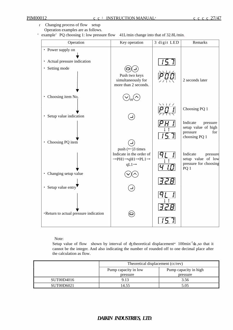
・ Changing process of flow setup Operation examples are as follows.
<example>PQ choosing 1: low pressure flow 41L/min change into that of 32.8L/min.
Note:
Setup value of flow shown by interval of 〔theoretical displacement×100min-1〕,so that it cannot be the integer. And also indicating the number of rounded off to one decimal place after the calculation as flow.
Theoretical displacement (cc/rev) Pump capacity in low
pressure Pump capacity in high
pressure SUT00D4016 9.13 3.56 SUT00D6021 14.55 5.05
Operation Key operation 3 d ig i t LED Remarks
・ Power supply on
・ Actual pressure indication
・ Setting mode
Push two keys simultaneously for
more than 2 seconds.
2 seconds later
・ Choosing item No. or
Choosing PQ 1
・ Setup value indication
↓↑
Indicate pressure setup value of high pressure for choosing PQ 1
・ Choosing PQ item push (←)3 times
Indicate in the order of →PH1→qH1→PL1→
qL1→
↓↑
Indicate pressuresetup value of lowpressure for choosingPQ 1
・ Changing setup value
・ Setup value entry
↓↑
・Return to actual pressure indication
PIM00012 【INSTRUCTION MANUAL】 28/47
DAIKIN INDUSTRIES, LTD.
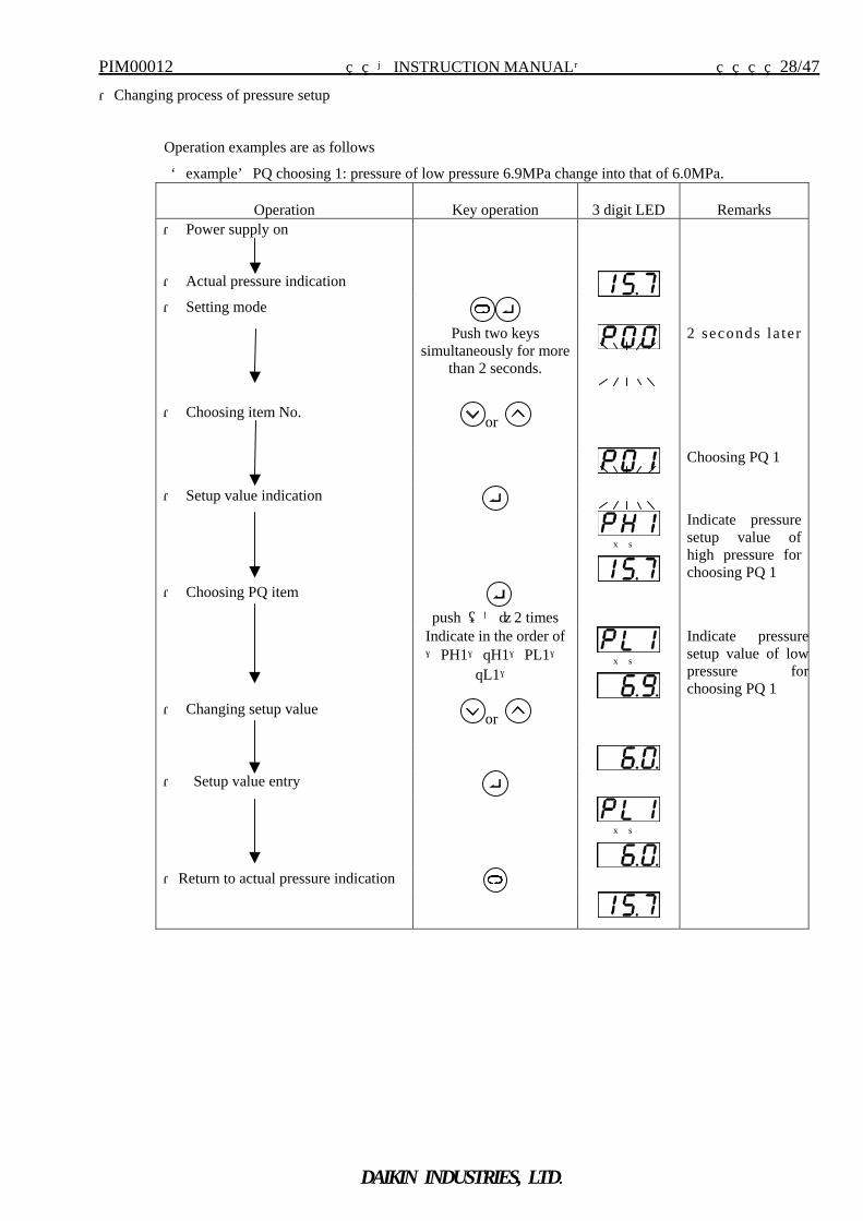
・Changing process of pressure setup
Operation examples are as follows
<example>PQ choosing 1: pressure of low pressure 6.9MPa change into that of 6.0MPa.
Operation
Key operation
3 digit LED
Remarks ・ Power supply on
・ Actual pressure indication
・ Setting mode
Push two keys simultaneously for more
than 2 seconds.
2 seconds la te r
・ Choosing item No. or
Choosing PQ 1
・ Setup value indication
↓↑
Indicate pressure setup value of high pressure for choosing PQ 1
・ Choosing PQ item push (←)2 times
Indicate in the order of →PH1→qH1→PL1→
qL1→
↓↑
Indicate pressuresetup value of lowpressure forchoosing PQ 1
・ Changing setup value or
・ Setup value entry
↓↑
・Return to actual pressure indication
PIM00012 【INSTRUCTION MANUAL】 29/47
DAIKIN INDUSTRIES, LTD.
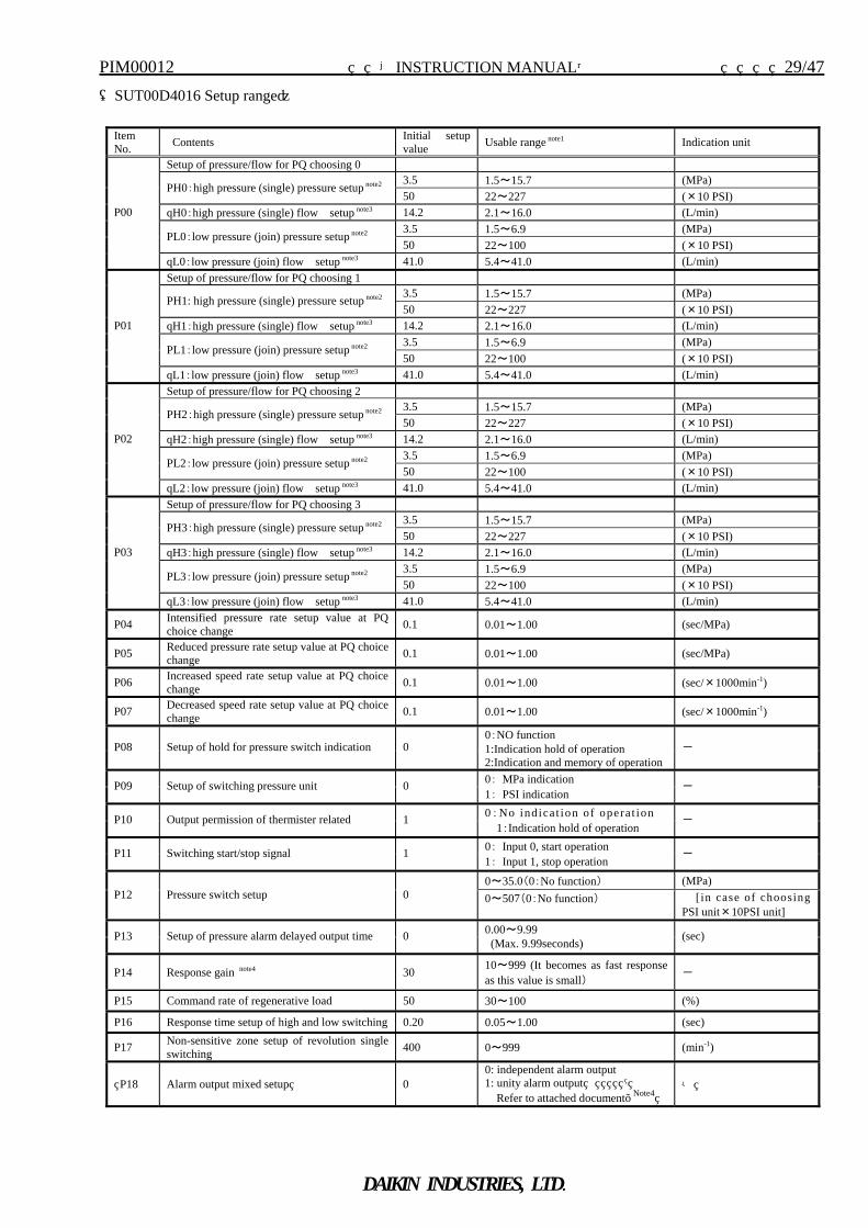
(SUT00D4016 Setup range)
Item No. Contents Initial setup
value Usable range note1 Indication unit
Setup of pressure/flow for PQ choosing 0 3.5 1.5~15.7 (MPa)
PH0:high pressure (single) pressure setup note2 50 22~227 (×10 PSI)
qH0:high pressure (single) flow setup note3 14.2 2.1~16.0 (L/min) 3.5 1.5~6.9 (MPa)
PL0:low pressure (join) pressure setup note2 50 22~100 (×10 PSI)
P00
qL0:low pressure (join) flow setup note3 41.0 5.4~41.0 (L/min) Setup of pressure/flow for PQ choosing 1
3.5 1.5~15.7 (MPa) PH1: high pressure (single) pressure setup note2 50 22~227 (×10 PSI)
qH1:high pressure (single) flow setup note3 14.2 2.1~16.0 (L/min) 3.5 1.5~6.9 (MPa)
PL1:low pressure (join) pressure setup note2 50 22~100 (×10 PSI)
P01
qL1:low pressure (join) flow setup note3 41.0 5.4~41.0 (L/min) Setup of pressure/flow for PQ choosing 2
3.5 1.5~15.7 (MPa) PH2:high pressure (single) pressure setup note2
50 22~227 (×10 PSI) qH2:high pressure (single) flow setup note3 14.2 2.1~16.0 (L/min)
3.5 1.5~6.9 (MPa) PL2:low pressure (join) pressure setup note2
50 22~100 (×10 PSI)
P02
qL2:low pressure (join) flow setup note3 41.0 5.4~41.0 (L/min) Setup of pressure/flow for PQ choosing 3
3.5 1.5~15.7 (MPa) PH3:high pressure (single) pressure setup note2
50 22~227 (×10 PSI) qH3:high pressure (single) flow setup note3 14.2 2.1~16.0 (L/min)
3.5 1.5~6.9 (MPa) PL3:low pressure (join) pressure setup note2
50 22~100 (×10 PSI)
P03
qL3:low pressure (join) flow setup note3 41.0 5.4~41.0 (L/min)
P04 Intensified pressure rate setup value at PQ choice change 0.1 0.01~1.00 (sec/MPa)
P05 Reduced pressure rate setup value at PQ choice change 0.1 0.01~1.00 (sec/MPa)
P06 Increased speed rate setup value at PQ choice change 0.1 0.01~1.00 (sec/×1000min-1)
P07 Decreased speed rate setup value at PQ choice change 0.1 0.01~1.00 (sec/×1000min-1)
P08 Setup of hold for pressure switch indication 0 0:NO function 1:Indication hold of operation 2:Indication and memory of operation
-
P09 Setup of switching pressure unit 0 0: MPa indication 1: PSI indication
-
P10 Output permission of thermister related 1 0:No indica t ion of opera t ion 1:Indication hold of operation
-
P11 Switching start/stop signal 1 0: Input 0, start operation 1: Input 1, stop operation
-
0~35.0(0:No function) (MPa) P12 Pressure switch setup 0 0~507(0:No function)
[ in case of choosing
PSI unit×10PSI unit]
P13 Setup of pressure alarm delayed output time 0 0.00~9.99 (Max. 9.99seconds) (sec)
P14 Response gain note4 30 10~999 (It becomes as fast response as this value is small) -
P15 Command rate of regenerative load 50 30~100 (%)
P16 Response time setup of high and low switching 0.20 0.05~1.00 (sec)
P17 Non-sensitive zone setup of revolution single switching 400 0~999 (min-1)
P18 Alarm output mixed setup 0 0: independent alarm output 1: unity alarm output
Refer to attached document. Note4 -
PIM00012 【INSTRUCTION MANUAL】 30/47
DAIKIN INDUSTRIES, LTD.
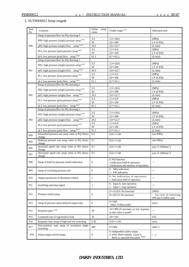
(SUT00D6021 Setup range)
Item No. Contents Initial setup
value Usable range note1 Indication unit
Setup of pressure/flow for PQ choosing 0 3.5 1.5~20.6 (MPa)
PH0:high pressure (single) pressure setup note2 50 22~298 (×10 PSI)
qH0:high pressure (single) flow setup note3 20.2 3.0~22.7 (L/min) 3.5 1.5~6.9 (MPa)
PL0:low pressure (join) pressure setup note2 50 22~100 (×10 PSI)
P00
qL0:low pressure (join) flow setup note3 61.1 8.7~61.1 (L/min) Setup of pressure/flow for PQ choosing 1
3.5 1.5~20.6 (MPa) PH1: high pressure (single) pressure setup note2 50 22~298 (×10 PSI)
qH1:high pressure (single) flow setup note3 20.2 3.0~22.7 (L/min) 3.5 1.5~6.9 (MPa)
PL1:low pressure (join) pressure setup note2 50 22~100 (×10 PSI)
P01
qL1:low pressure (join) flow setup note3 61.1 8.7~61.1 (L/min) Setup of pressure/flow for PQ choosing 2
3.5 1.5~20.6 (MPa) PH2:high pressure (single) pressure setup note2
50 22~298 (×10 PSI) qH2:high pressure (single) flow setup note3 20.2 3.0~22.7 (L/min)
3.5 1.5~6.9 (MPa) PL2:low pressure (join) pressure setup note2
50 22~100 (×10 PSI)
P02
qL2:low pressure (join) flow setup note3 61.1 8.7~61.1 (L/min) Setup of pressure/flow for PQ choosing 3
3.5 1.5~20.6 (MPa) PH3:high pressure (single) pressure setup note2
50 22~298 (×10 PSI) qH3:high pressure (single) flow setup note3 20.2 3.0~22.7 (L/min)
3.5 1.5~6.9 (MPa) PL3:low pressure (join) pressure setup note2
50 22~100 (×10 PSI)
P03
qL3:low pressure (join) flow setup note3 61.1 8.7~61.1 (L/min)
P04 Intensified pressure rate setup value at PQ choice change
0.1 0.01~1.00 (sec/MPa)
P05 Reduced pressure rate setup value at PQ choice change
0.1 0.01~1.00 (sec/MPa)
P06 Increased speed rate setup value at PQ choice change
0.1 0.01~1.00 (sec/×1000min-1)
P07 Decreased speed rate setup value at PQ choice change
0.1 0.01~1.00 (sec/×1000min-1)
P08 Setup of hold for pressure switch indication 0 0:NO function 1:Indication hold of operation 2:Indication and memory of operation
-
P09 Setup of switching pressure unit 0 0: MPa indication 1: PSI indication
-
P10 Output permission of thermister related 1 0:No indica t ion of opera t ion 1:Indication hold of operation
-
P11 Switching start/stop signal 1 0: Input 0, start operation 1: Input 1, stop operation
-
0~35.0(0:No function) (MPa) P12 Pressure switch setup 0 0~507(0:No function)
[ in case of choosing
PSI unit×10PSI unit]
P13 Setup of pressure alarm delayed output time 0 0~999 (Max. 9.99seconds)
(sec)
P14 Response gain note4 30 10~999 (It becomes as fast response as this value is small) -
P15 Command rate of regenerative load 50 30~100 (%)
P16 Response time setup of high and low switching 0.20 0.05~1.00 (sec)
P17 Non-sensitive zone setup of revolution single switching 400 0~999 (min-1)
P18 Alarm output mixed setup 0 0: independent alarm output 1: unity alarm output
Refer to attached document. note5 -
PIM00012 【INSTRUCTION MANUAL】 31/47
DAIKIN INDUSTRIES, LTD.
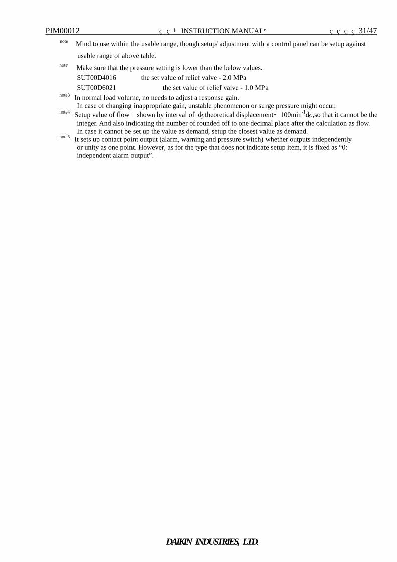
note1 Mind to use within the usable range, though setup/ adjustment with a control panel can be setup against
usable range of above table. note2 Make sure that the pressure setting is lower than the below values.
SUT00D4016 the set value of relief valve - 2.0 MPa SUT00D6021 the set value of relief valve - 1.0 MPa note3 In normal load volume, no needs to adjust a response gain. In case of changing inappropriate gain, unstable phenomenon or surge pressure might occur. note4 Setup value of flow shown by interval of 〔theoretical displacement×100min-1〕,so that it cannot be the integer. And also indicating the number of rounded off to one decimal place after the calculation as flow. In case it cannot be set up the value as demand, setup the closest value as demand. note5 It sets up contact point output (alarm, warning and pressure switch) whether outputs independently or unity as one point. However, as for the type that does not indicate setup item, it is fixed as “0: independent alarm output”.
PIM00012 【INSTRUCTION MANUAL】 32/47
DAIKIN INDUSTRIES, LTD.
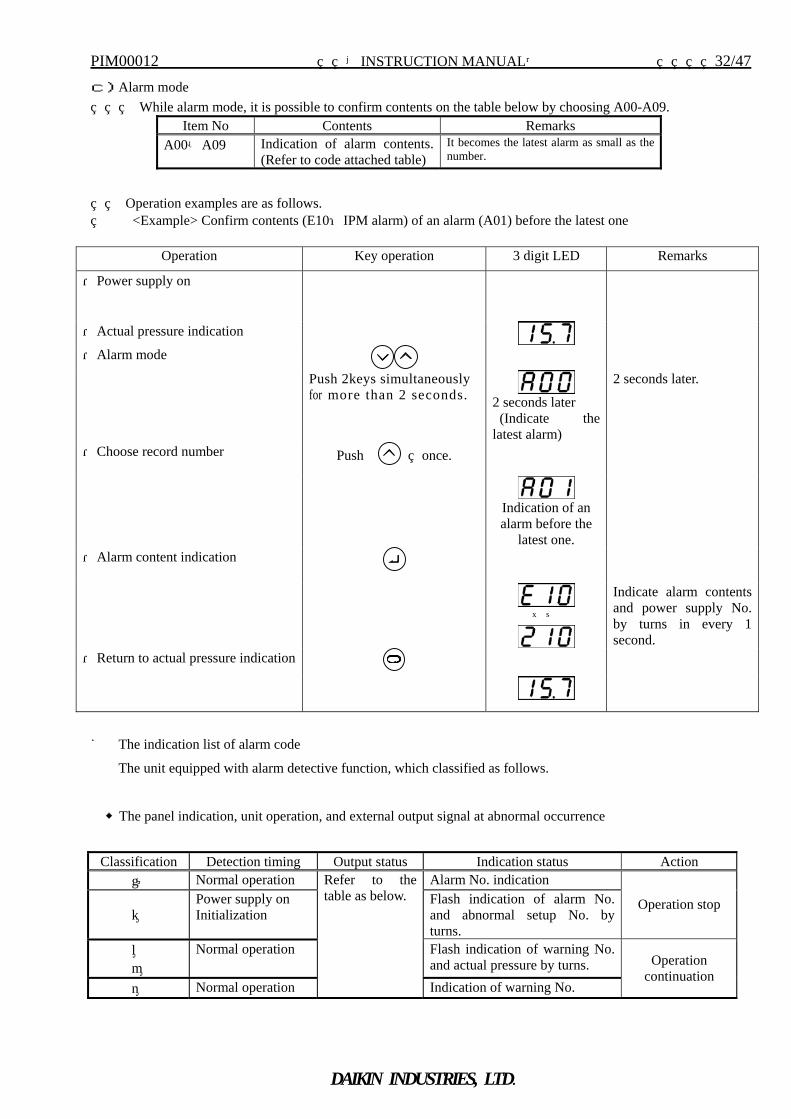
c)Alarm mode While alarm mode, it is possible to confirm contents on the table below by choosing A00-A09.
Operation examples are as follows. <Example> Confirm contents (E10:IPM alarm) of an alarm (A01) before the latest one
■ The indication list of alarm code
The unit equipped with alarm detective function, which classified as follows.
◆The panel indication, unit operation, and external output signal at abnormal occurrence
Item No Contents Remarks A00-A09 Indication of alarm contents.
(Refer to code attached table) It becomes the latest alarm as small as the number.
Operation Key operation 3 digit LED Remarks
・Power supply on
・Actual pressure indication
・Alarm mode
Push 2keys simultaneously for more than 2 seconds.
2 seconds later (Indicate the latest alarm)
2 seconds later.
・Choose record number Push once.
Indication of an alarm before the
latest one.
・Alarm content indication
↓↑
Indicate alarm contents and power supply No. by turns in every 1 second.
・Return to actual pressure indication
Classification Detection timing Output status Indication status Action ① Normal operation Alarm No. indication
② Power supply on Initialization
Flash indication of alarm No. and abnormal setup No. by turns.
Operation stop
③ ④
Normal operation Flash indication of warning No. and actual pressure by turns.
⑤ Normal operation
Refer to the table as below.
Indication of warning No.
Operation continuation
PIM00012 【INSTRUCTION MANUAL】 33/47
DAIKIN INDUSTRIES, LTD.
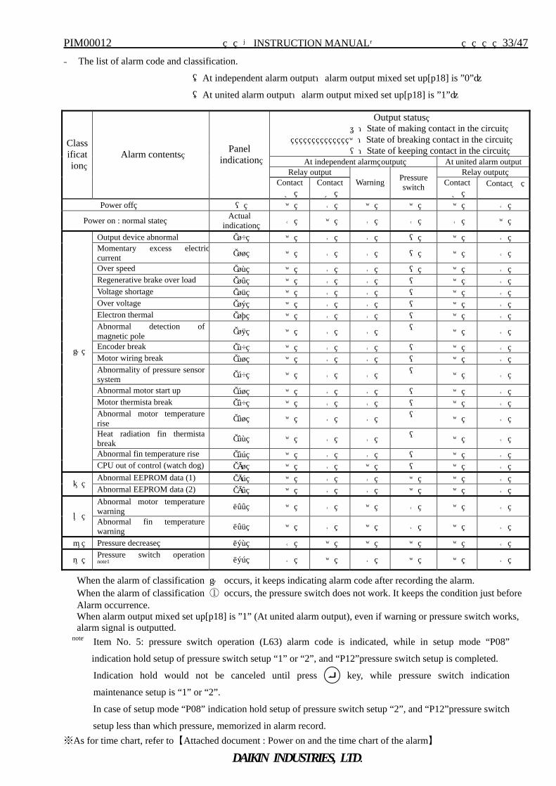
◆ The list of alarm code and classification.
(At independent alarm output:alarm output mixed set up[p18] is ”0”)
(At united alarm output:alarm output mixed set up[p18] is ”1”)
When the alarm of classification ① occurs, it keeps indicating alarm code after recording the alarm. When the alarm of classification ① occurs, the pressure switch does not work. It keeps the condition just before Alarm occurrence. When alarm output mixed set up[p18] is ”1” (At united alarm output), even if warning or pressure switch works, alarm signal is outputted.
note1 Item No. 5: pressure switch operation (L63) alarm code is indicated, while in setup mode “P08”
indication hold setup of pressure switch setup “1” or “2”, and “P12”pressure switch setup is completed.
Indication hold would not be canceled until press key, while pressure switch indication
maintenance setup is “1” or “2”.
In case of setup mode “P08” indication hold setup of pressure switch setup “2”, and “P12”pressure switch
setup less than which pressure, memorized in alarm record. ※As for time chart, refer to 【Attached document : Power on and the time chart of the alarm】
Output status 〇:State of making contact in the circuit
×:State of breaking contact in the circuit ―:State of keeping contact in the circuit
At independent alarm output At united alarm outputRelay output Relay output
Classification
Alarm contents Panel indication
ContactA
ContactB
Warning Pressure switch Contact
A ContactB
Power off ― × ○ × × × ○
Power on : normal state Actual indication ○ × ○ ○ ○ ×
Output device abnormal E10 × ○ ○ ― × ○ Momentary excess electriccurrent E11 × ○ ○ ― × ○
Over speed E12 × ○ ○ ― × ○ Regenerative brake over load E14 × ○ ○ ― × ○ Voltage shortage E15 × ○ ○ ― × ○ Over voltage E16 × ○ ○ ― × ○ Electron thermal E17 × ○ ○ ― × ○ Abnormal detection of magnetic pole E18 × ○ ○ ― × ○
Encoder break E20 × ○ ○ ― × ○ Motor wiring break E21 × ○ ○ ― × ○ Abnormality of pressure sensor system E30 × ○ ○ ― × ○
Abnormal motor start up E31 × ○ ○ ― × ○ Motor thermista break E40 × ○ ○ ― × ○ Abnormal motor temperature rise E41 × ○ ○ ― × ○
Heat radiation fin thermista break E42 × ○ ○ ― × ○
Abnormal fin temperature rise E43 × ○ ○ ― × ○
①
CPU out of control (watch dog) E91 × ○ × ― × ○ Abnormal EEPROM data (1) E93 × ○ ○ × × ○ ② Abnormal EEPROM data (2) E94 × ○ ○ × × ○ Abnormal motor temperature warning L44 × ○ × ○ × ○
③ Abnormal fin temperature warning L45 × ○ × ○ × ○
④ Pressure decrease L62 ○ × × × × ○
⑤ Pressure switch operation note1 L63 ○ × ○ × × ○
PIM00012 【INSTRUCTION MANUAL】 34/47
DAIKIN INDUSTRIES, LTD.
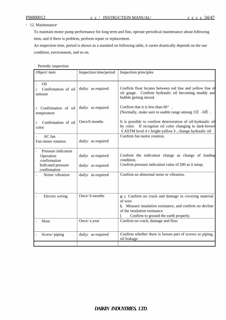
【12. Maintenance】
To maintain motor pump performance for long term and fine, operate periodical maintenance about following
item, and if there is problem, perform repair or replacement.
An inspection time, period is shown as a standard on following table, it varies drastically depends on the use
condition, environment, and so on.
■Periodic inspection Object/ item Inspection time/period Inspection principles
● Oil ・ Confirmation of oil amount ・ Confirmation of oil temperature
・ Confirmation of oil color
daily・as required daily・as required Once/6 months
Confirm float locates between red line and yellow line ofoil gauge. Confirm hydraulic oil becoming muddy andbubble getting mixed. Confirm that it is less than 60°. (Normally, make sure to usable range among 15℃-50℃. It is possible to confirm deterioration of oil-hydraulic oilby color. If recognize oil color changing to dark-brown(ASTM level 4:bright-yellow), change hydraulic oil
● AC fan Fan motor rotation
daily・as required
Confirm fan motor rotation.
● Pressure indication Operation confirmation Indicated pressure confirmation
daily・as required daily・as required
Confirm the indication change as change of loadingcondition. Confirm pressure indication value of DH as it setup.
● Noise/ vibration daily・as required Confirm no abnormal noise or vibration.
● Electric wiring Once/ 6 months ① Confirm no crack and damage in covering material of wire. ② Measure insulation resistance, and confirm no decline of the insulation resistance ③ Confirm to ground the earth properly.
● Hose Once/ a year Confirm no crack, damage and flaw.
● Screw/ piping daily・as required Confirm whether there is loosen part of screws or piping, oil leakage.
PIM00012 【INSTRUCTION MANUAL】 35/47
DAIKIN INDUSTRIES, LTD.
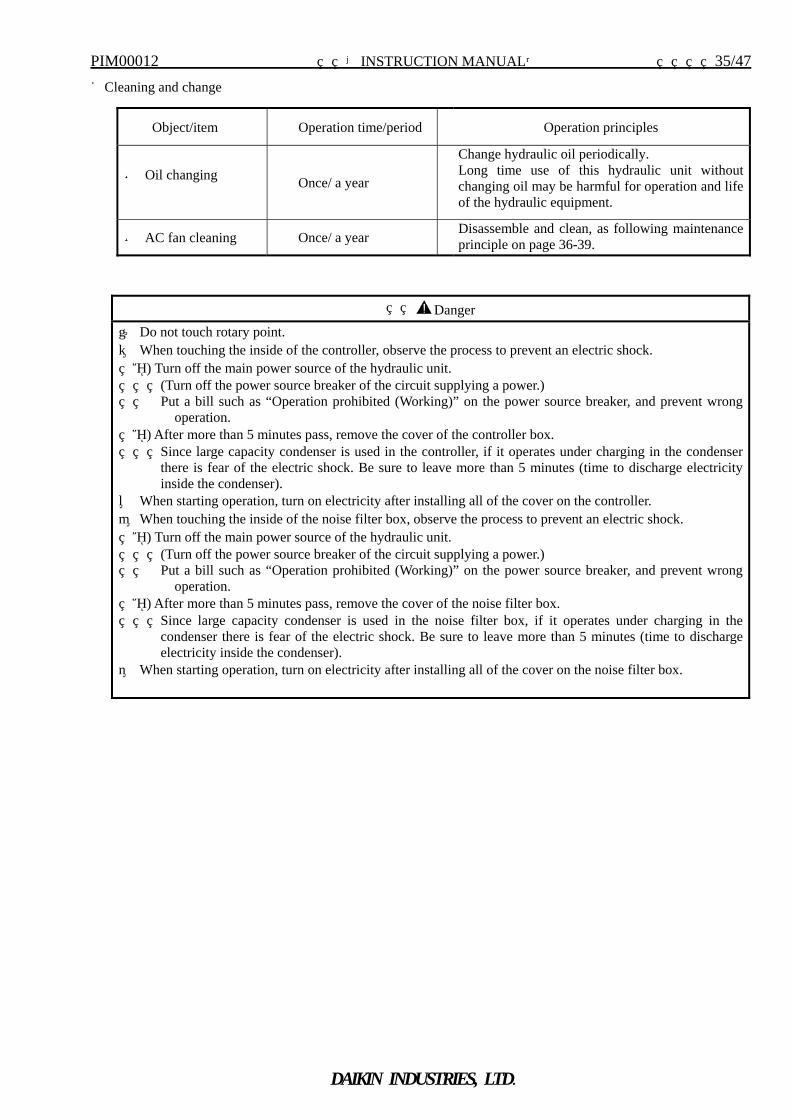
■Cleaning and change
Object/item Operation time/period Operation principles
● Oil changing Once/ a year
Change hydraulic oil periodically. Long time use of this hydraulic unit without changing oil may be harmful for operation and life of the hydraulic equipment.
● AC fan cleaning Once/ a year Disassemble and clean, as following maintenance principle on page 36-39.
Danger
① Do not touch rotary point. ② When touching the inside of the controller, observe the process to prevent an electric shock. ⅰ) Turn off the main power source of the hydraulic unit. (Turn off the power source breaker of the circuit supplying a power.) Put a bill such as “Operation prohibited (Working)” on the power source breaker, and prevent wrong
operation. ⅱ) After more than 5 minutes pass, remove the cover of the controller box. Since large capacity condenser is used in the controller, if it operates under charging in the condenser
there is fear of the electric shock. Be sure to leave more than 5 minutes (time to discharge electricity inside the condenser).
③ When starting operation, turn on electricity after installing all of the cover on the controller. ④ When touching the inside of the noise filter box, observe the process to prevent an electric shock. ⅰ) Turn off the main power source of the hydraulic unit. (Turn off the power source breaker of the circuit supplying a power.) Put a bill such as “Operation prohibited (Working)” on the power source breaker, and prevent wrong
operation. ⅱ) After more than 5 minutes pass, remove the cover of the noise filter box. Since large capacity condenser is used in the noise filter box, if it operates under charging in the
condenser there is fear of the electric shock. Be sure to leave more than 5 minutes (time to discharge electricity inside the condenser).
⑤ When starting operation, turn on electricity after installing all of the cover on the noise filter box.
PIM00012 【INSTRUCTION MANUAL】 36/47
DAIKIN INDUSTRIES, LTD.
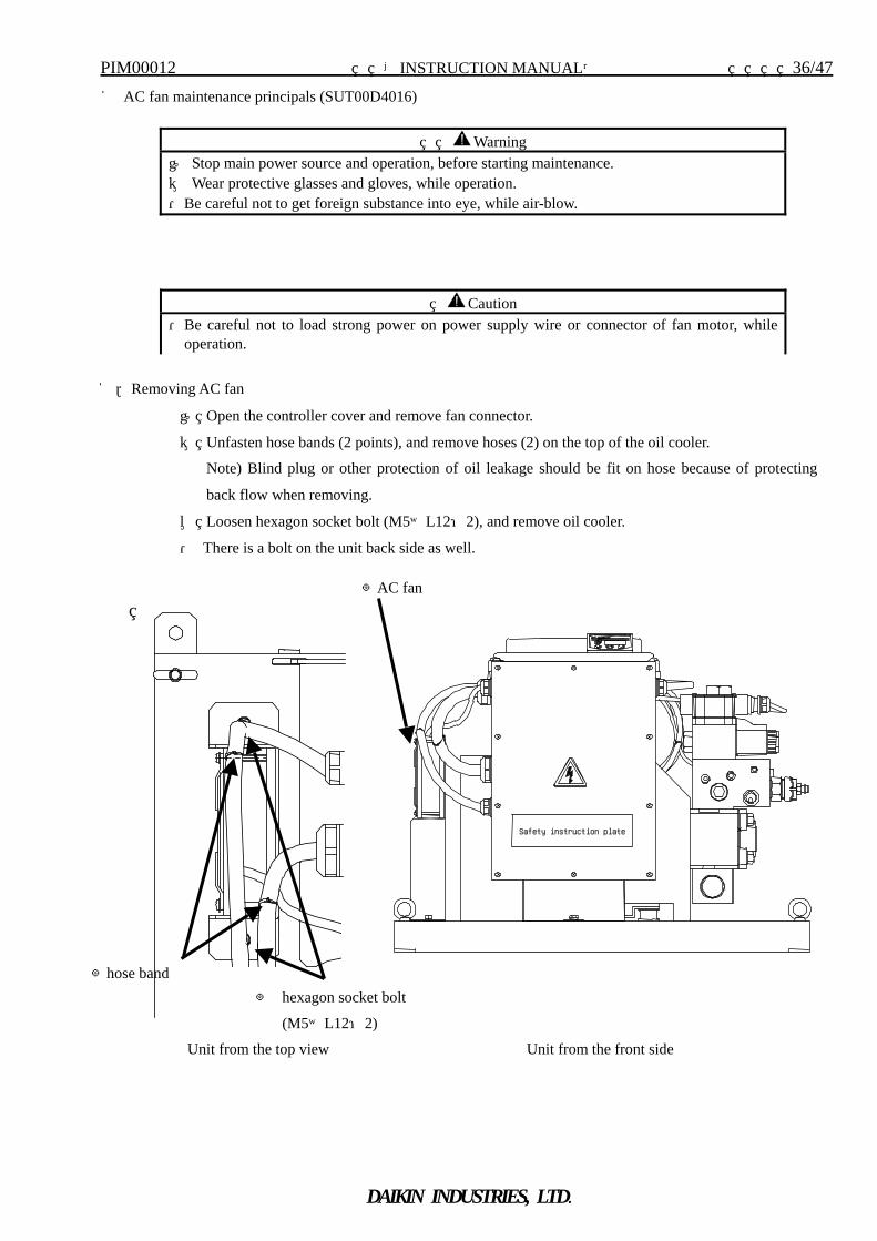
■ AC fan maintenance principals (SUT00D4016)
1.Removing AC fan
① Open the controller cover and remove fan connector.
② Unfasten hose bands (2 points), and remove hoses (2) on the top of the oil cooler.
Note) Blind plug or other protection of oil leakage should be fit on hose because of protecting
back flow when removing.
③ Loosen hexagon socket bolt (M5×L12:2), and remove oil cooler.
・ There is a bolt on the unit back side as well.
Warning ① Stop main power source and operation, before starting maintenance. ② Wear protective glasses and gloves, while operation. ・Be careful not to get foreign substance into eye, while air-blow.
Caution ・Be careful not to load strong power on power supply wire or connector of fan motor, while
operation.
Safety instruction plate
◎ hexagon socket bolt
(M5×L12:2)
Unit from the front side
◎AC fan
◎hose band
Unit from the top view
PIM00012 【INSTRUCTION MANUAL】 37/47
DAIKIN INDUSTRIES, LTD.
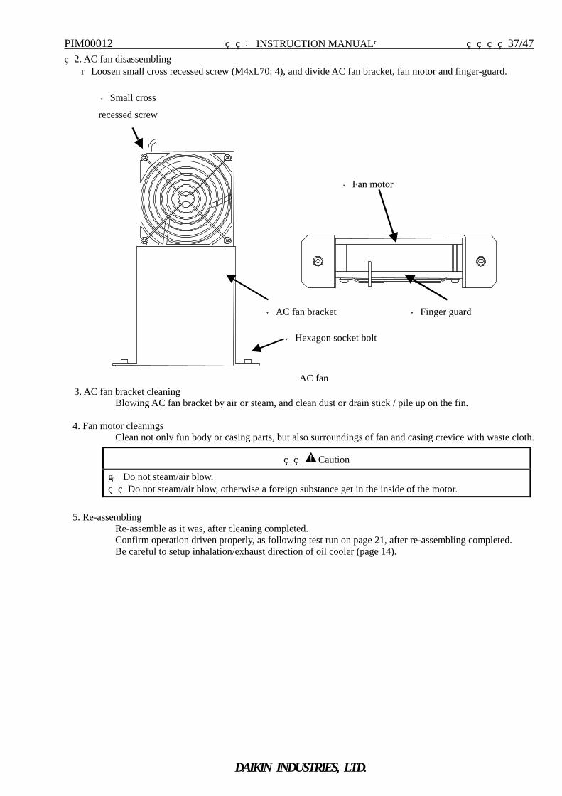
2. AC fan disassembling ・Loosen small cross recessed screw (M4xL70: 4), and divide AC fan bracket, fan motor and finger-guard.
3. AC fan bracket cleaning Blowing AC fan bracket by air or steam, and clean dust or drain stick / pile up on the fin.
4. Fan motor cleanings Clean not only fun body or casing parts, but also surroundings of fan and casing crevice with waste cloth.
5. Re-assembling
Re-assemble as it was, after cleaning completed. Confirm operation driven properly, as following test run on page 21, after re-assembling completed. Be careful to setup inhalation/exhaust direction of oil cooler (page 14).
Caution
① Do not steam/air blow. Do not steam/air blow, otherwise a foreign substance get in the inside of the motor.
◎Hexagon socket bolt
◎Fan motor
AC fan
◎Small cross
recessed screw
◎AC fan bracket
◎Finger guard
PIM00012 【INSTRUCTION MANUAL】 38/47
DAIKIN INDUSTRIES, LTD.
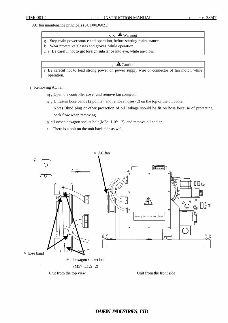
■ AC fan maintenance principals (SUT00D6021)
1.Removing AC fan
④ Open the controller cover and remove fan connector.
⑤ Unfasten hose bands (2 points), and remove hoses (2) on the top of the oil cooler.
Note) Blind plug or other protection of oil leakage should be fit on hose because of protecting
back flow when removing.
⑥ Loosen hexagon socket bolt (M5×L16:2), and remove oil cooler.
・ There is a bolt on the unit back side as well.
Warning ① Stop main power source and operation, before starting maintenance. ② Wear protective glasses and gloves, while operation. ・Be careful not to get foreign substance into eye, while air-blow.
Caution ・Be careful not to load strong power on power supply wire or connector of fan motor, while
operation.
Safety instruction plate
◎ hexagon socket bolt
(M5×L12:2)
Unit from the front side
◎AC fan
◎hose band
Unit from the top view
PIM00012 【INSTRUCTION MANUAL】 39/47
DAIKIN INDUSTRIES, LTD.
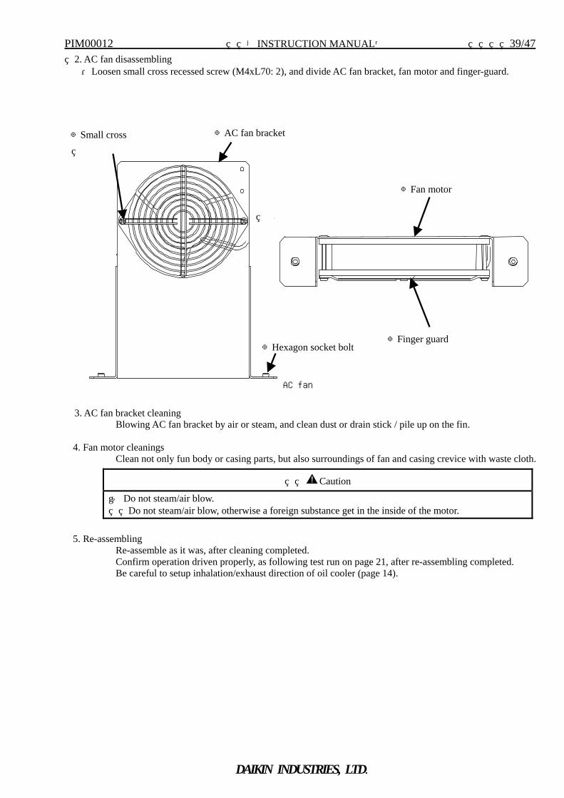
2. AC fan disassembling ・Loosen small cross recessed screw (M4xL70: 2), and divide AC fan bracket, fan motor and finger-guard.
3. AC fan bracket cleaning Blowing AC fan bracket by air or steam, and clean dust or drain stick / pile up on the fin.
4. Fan motor cleanings Clean not only fun body or casing parts, but also surroundings of fan and casing crevice with waste cloth.
5. Re-assembling
Re-assemble as it was, after cleaning completed. Confirm operation driven properly, as following test run on page 21, after re-assembling completed. Be careful to setup inhalation/exhaust direction of oil cooler (page 14).
Caution
① Do not steam/air blow. Do not steam/air blow, otherwise a foreign substance get in the inside of the motor.
◎Hexagon socket bolt
◎Fan motor
◎Finger guard
AC fan
◎Small cross
d
◎AC fan bracket
PIM00012 【INSTRUCTION MANUAL】 40/47
DAIKIN INDUSTRIES, LTD.
Pres
ent n
umbe
r of r
otat
ion
Length of pressure adjustment screw
Operation start point
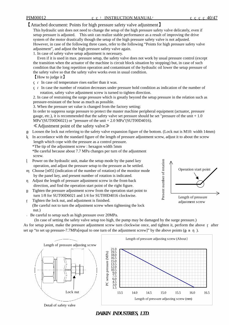
【Attached document: Points for high pressure safety valve adjustment】 This hydraulic unit does not need to change the setup of the high pressure safety valve delicately, even if setup pressure is adjusted. This unit can realize stable performance as a result of improving the drive system of the motor drastically though the setup of the high pressure safety valve is not adjusted. However, in case of the following three cases, refer to the following “Points for high pressure safety valve adjustment”, and adjust the high pressure safety valve again. 1. In case of safety valve setup adjustment is necessary. Even if it is used in max. pressure setup, the safety valve does not work by usual pressure control (except the transition when the actuator of the machine is circuit block situation by stopping) but, in case of such condition that the long repetition operation and contaminant of the hydraulic oil lower the setup pressure of the safety valve so that the safety valve works even in usual condition. 【How to judge it】 ・In case oil temperature rises earlier than it was. ・In case the number of rotation decreases under pressure hold condition as indication of the number of
rotation, safety valve adjustment screw is turned to tighten direction. 2. In case of restraining the surge pressure which is greatly beyond the setup pressure in the relation such as pressure-resistant of the hose as much as possible. 3. When the pressure set value is changed from the factory setting: In order to suppress surge pressure to protect the master machine peripheral equipment (actuator, pressure gauge, etc.), it is recommended that the safety valve set pressure should be set "pressure of the unit + 1.0 MPa"(SUT00D6021) or "pressure of the unit + 2.0 MPa"(SUT00D4016). ≪Adjustment point of the safety valve≫
① Loosen the lock nut referring to the safety valve expansion figure of the bottom. (Lock nut is M10: width 14mm) ② In accordance with the standard figure of the length of pressure adjustment screw, adjust it to about the screw
length which cope with the pressure as a control pressure. *The tip of the adjustment screw : hexagon width 5mm *Be careful because about 7.7 MPa changes per turn of the adjustment
screw. ③ Power on the hydraulic unit, make the setup mode by the panel key
operation, and adjust the pressure setup to the pressure as be settled. ④ Choose [n05] (indication of the number of rotation) of the monitor mode
by the panel key, and present number of rotation is indicated. ⑤ Adjust the length of pressure adjustment screw in the front-back
direction, and find the operation start point of the right figure. ⑥ Tighten the pressure adjustment screw from the operation start point to
turn 1/8 for SUT00D6021 and 1/4 for SUT00D4016 clockwise. ⑦ Tighten the lock nut, and adjustment is finished. (Be careful not to turn the adjustment screw when tightening the lock
nut.) ★Be careful to setup such as high pressure over 20MPa.
(In case of setting the safety valve setup too high, the pump may be damaged by the surge pressure.) As for setup point, make the pressure adjustment screw turn clockwise once, and tighten it, perform the above ⑦after set up “to set up pressure-7.7MPa[equal to one turn of the adjustment screw]” by the above points (①~⑤).
Lock nut
Length of pressure adjusting screw
Detail of safety valve
Length of pressure adjusting screw (About)
1.53.04.56.07.59.0
10.512.013.515.016.518.019.521.0
13.5 14.0 14.5 15.0 15.5 16.0 16.5
Length of pressure adjusting screw (mm)
PC se
tup
pres
sure
(MPa
)
PIM00012 【INSTRUCTION MANUAL】 41/47
DAIKIN INDUSTRIES, LTD.
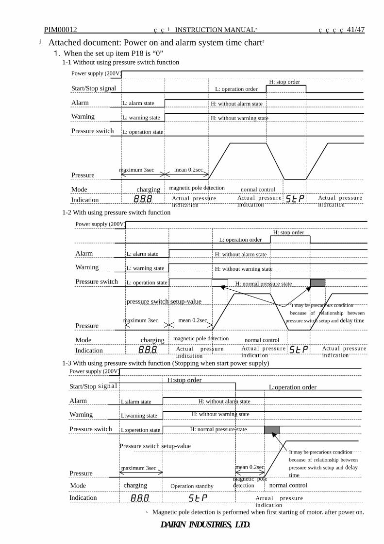
【Attached document: Power on and alarm system time chart】 1.When the set up item P18 is “0”
1-1 Without using pressure switch function
Actua l pressure indica t ion
Power supply (200V)
Start/Stop signal
Alarm
Pressure
Mode charging magnetic pole detection normal control
maximum 3sec
L: operation orderH: stop order
L: alarm state H: without alarm state
Warning L: warning state H: without warning state
Pressure switch L: operation state
mean 0.2sec
Indication Actua l pressure indica t ion
Actua l pressure indica t ion
1-2 With using pressure switch function
charging
maximum 3sec
L: alarm state
L: warning state
L: operation state
Power supply (200V)
Alarm
Pressure
Mode
Warning
Pressure switch
Indication Actua l pressure indica t ion
magnetic pole detection normal control
L: operation orderH: stop order
H: without alarm state
H: without warning state
mean 0.2sec
Actua l pressure indica t ion
Actua l pressure indica t ion
H: normal pressure state
pressure switch setup-value
1-3 With using pressure switch function (Stopping when start power supply) Power supply (200V)
Start/Stop signa l
Alarm
Pressure
Mode
Warning
Pressure switch
Indication
charging magnetic pole detection d t t i
normal control
maximum 3sec mean 0.2sec
L:operation order H:stop order
L:alarm state H: without alarm state
L:warning state H: without warning state
L:operetion state H: normal pressure state
Pressure switch setup-value
Operation standby
Actua l pressureindica t ion
※Magnetic pole detection is performed when first starting of motor. after power on.
It may be precarious condition because of relationship betweenpressure switch setup and delay time
It may be precarious condition because of relationship between
pressure switch setup and delay time
PIM00012 【INSTRUCTION MANUAL】 42/47
DAIKIN INDUSTRIES, LTD.
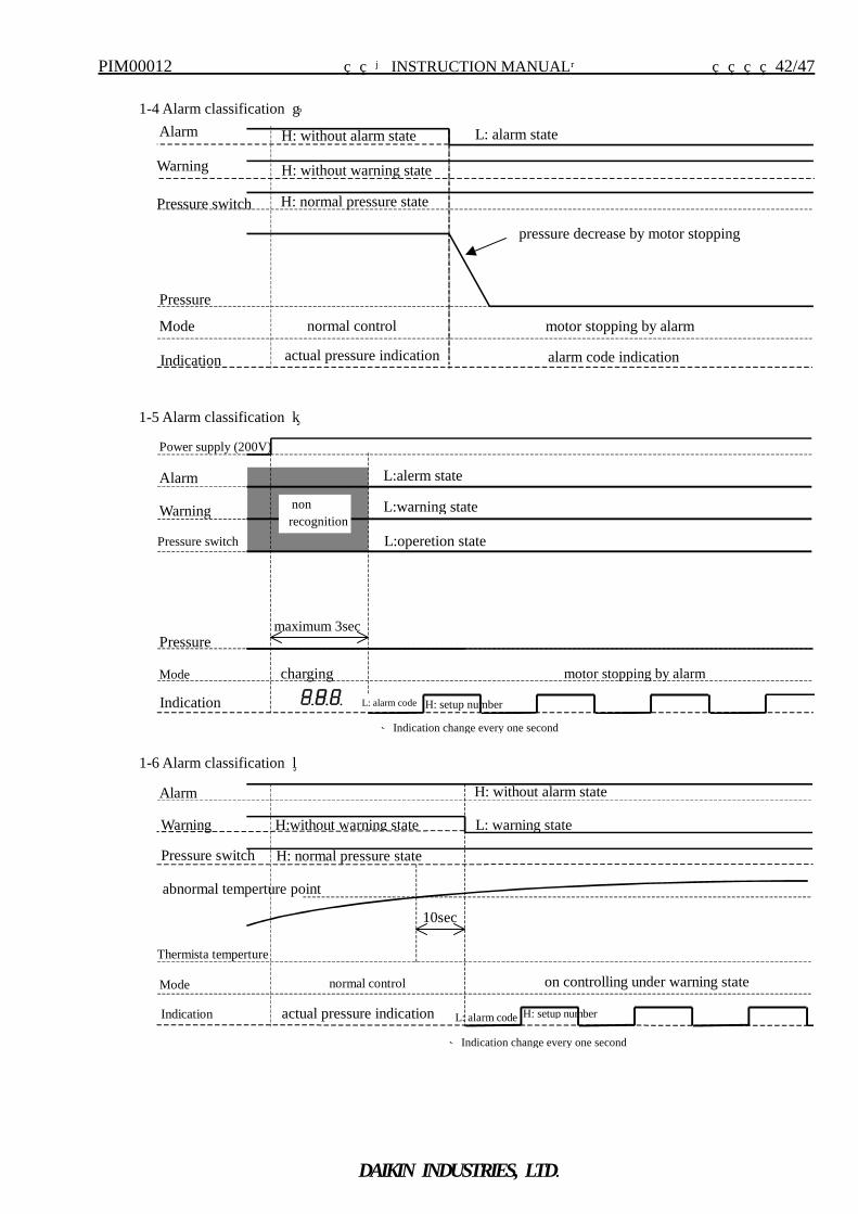
1-4 Alarm classification ①
Alarm
Pressure
Indication actual pressure indication
L: alarm state H: without alarm state
Warning H: without warning state
Pressure switch H: normal pressure state
alarm code indication
pressure decrease by motor stopping
Mode normal control motor stopping by alarm
1-5 Alarm classification ②
H: setup numberL: alarm code
Alarm
Pressure
Indication
Warning
Pressure switch
motor stopping by alarm
Power supply (200V)
charging
maximum 3sec
Mode
L:warning state
L:operetion state
L:alerm state
non recognition
1-6 Alarm classification ③
Alarm
Thermista temperture
Mode normal control
H: without alarm state
Warning L: warning state H:without warning state
Pressure switch H: normal pressure state
abnormal temperture point
10sec
actual pressure indication Indication
on controlling under warning state
H: setup numberL: alarm code
※Indication change every one second
※Indication change every one second
PIM00012 【INSTRUCTION MANUAL】 43/47
DAIKIN INDUSTRIES, LTD.
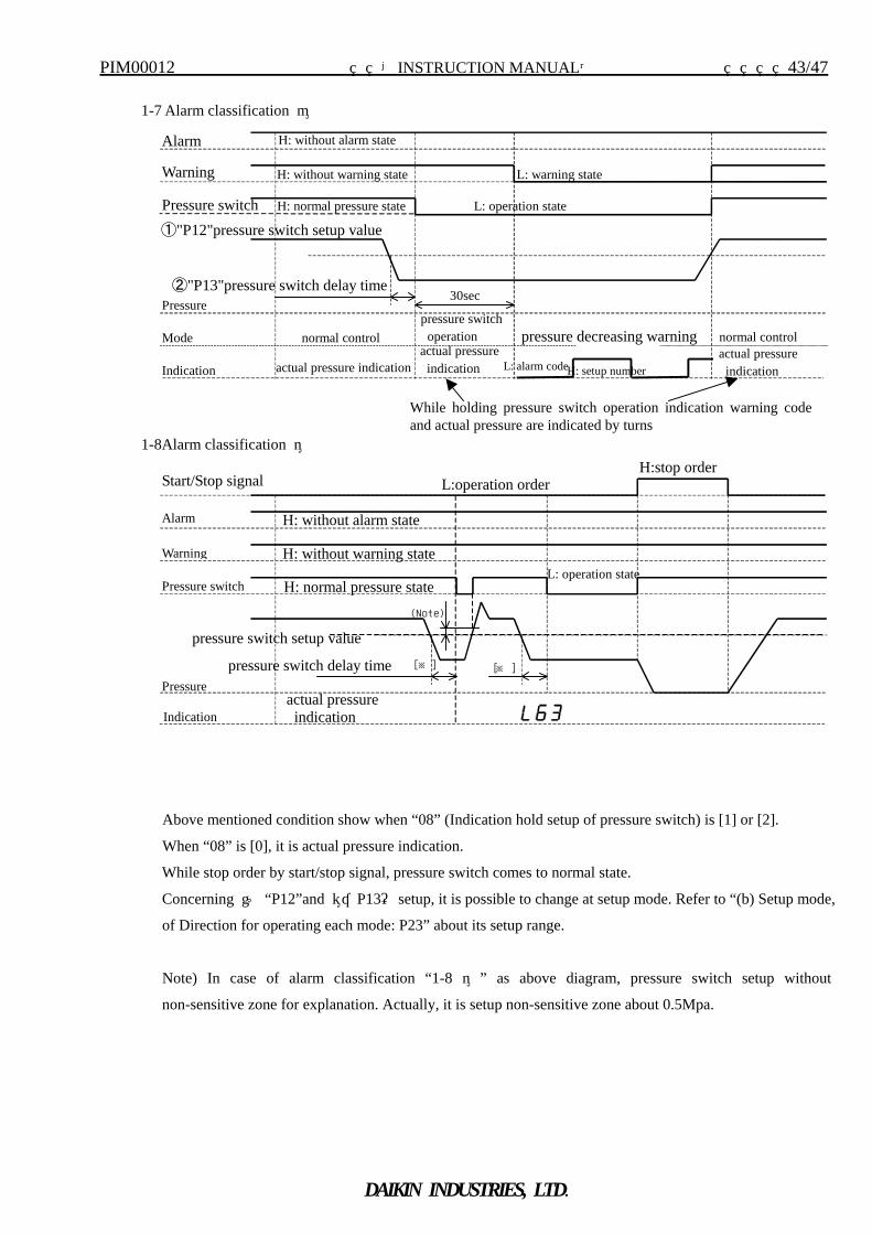
1-7 Alarm classification ④
Alarm
Pressure
Mode normal control
H: without alarm state
Warning H: without warning state
Pressure switch H: normal pressure state
①"P12"pressure switch setup value
②"P13"pressure switch delay time30sec
Indication actual pressure indication actual pressure indication
pressure switch operation pressure decreasing warning actual pressure indication H: setup number L: alarm code
normal control
L: warning state
L: operation state
1-8Alarm classification ⑤
Start/Stop signal
Alarm
Pressure
Indication actual pressure indication
L:operation orderH:stop order
H: without warning stateWarning
H: normal pressure state Pressure switch
pressure switch setup value
pressure switch delay time [※] [※ ]
H: without alarm state
L: operation state
Above mentioned condition show when “08” (Indication hold setup of pressure switch) is [1] or [2].
When “08” is [0], it is actual pressure indication.
While stop order by start/stop signal, pressure switch comes to normal state.
Concerning ① “P12”and ②“P13” setup, it is possible to change at setup mode. Refer to “(b) Setup mode,
of Direction for operating each mode: P23” about its setup range.
Note) In case of alarm classification “1-8 ⑤ ” as above diagram, pressure switch setup without
non-sensitive zone for explanation. Actually, it is setup non-sensitive zone about 0.5Mpa.
While holding pressure switch operation indication warning codeand actual pressure are indicated by turns
(Note)
PIM00012 【INSTRUCTION MANUAL】 44/47
DAIKIN INDUSTRIES, LTD.
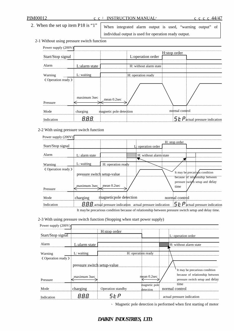
2.When the set up item P18 is “1”
2-1 Without using pressure switch function Power supply (200V)
Start/Stop signal
Alarm
Pressure
Mode charging magnetic pole detection normal control
maximum 3sec mean 0.2sec
L:operation order H:stop order
L:alarm state H: without alarm state
Warning (Operation ready)
L: waiting
Indication actual pressure indication
H: operation ready
2-2 With using pressure switch function Power supply (200V)
Start/Stop signal
Alarm
Pressure
Mode
Warning (Operation ready)
Indication
charging magneticpole detection normal control
maximum 3sec mean 0.2sec
L: operation orderH: stop order
L: alarm state H: without alarm state
pressure switch setup-value
L: waiting H: operation ready
actual pressure indication actual pressure indication actual pressure indication
2-3 With using pressure switch function (Stopping when start power supply) Power supply (200V)
Start/Stop signal
Alarm
Pressure
Mode charging magnetic poledetection normal control
maximum 3sec mean 0.2sec
L: operation orderH:stop order
L:alarm state H: without alarm state
pressure switch setup-value
Operation standby
Warning (Operation ready)
L: waiting H: operation ready
Indication actual pressure indication ※Magnetic pole detection is performed when first starting of motor
It may be precarious condition because of relationship between pressure switch setup and delay time.
It may be precarious condition because of relationship betweenpressure switch setup and delay time
When integrated alarm output is used, “warning output” of
individual output is used for operation ready output.
It may be precarious condition because of relationship betweenpressure switch setup and delay time
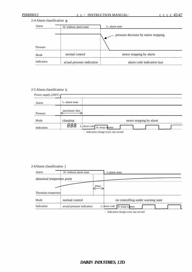
PIM00012 【INSTRUCTION MANUAL】 45/47
DAIKIN INDUSTRIES, LTD.
2-4 Alarm classification ① Alarm
Pressure
Indication actual pressure indication
L: alarm state H: without alarm state
alarm code indication flash
pressure decrease by motor stopping
Mode normal control motor stopping by alarm
2-5 Alarm classification ②
Alarm
Pressure
motor stopping by alarm
Power supply (200V)
charging
maximum 3sec
L: alarm state
Mode
Indication H: setup numberL: alarm code
2-6Alarm classification ③
Alarm
Thermista temperture
Mode normal control
L:alarm state
abnormal temperture point
10sec
on controlling under warning state
Indication actual pressure indication H: setup numberL: alarm code
H: without alarm state
※Indication change every one second
※Indication change every one second
PIM00012 【INSTRUCTION MANUAL】 46/47
DAIKIN INDUSTRIES, LTD.
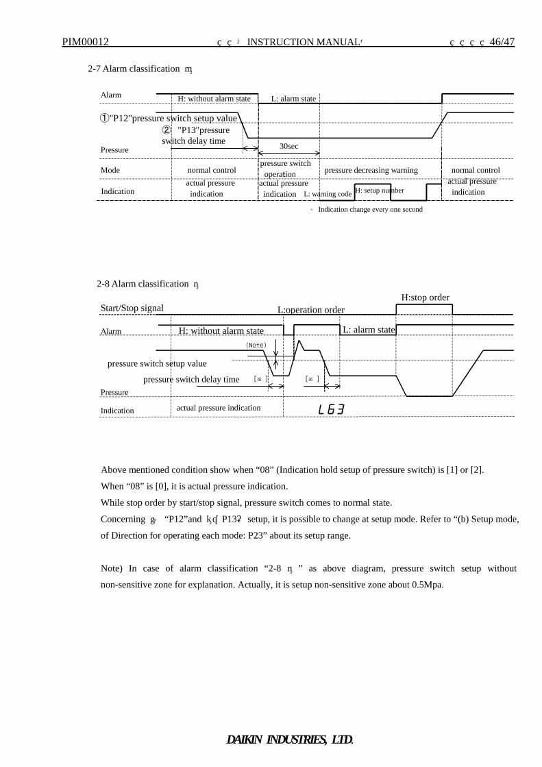
2-7 Alarm classification ④
Alarm
Pressure
Mode normal control
H: without alarm state
①"P12"pressure switch setup value ② "P13"pressureswitch delay time 30sec
normal control pressure switch operation pressure decreasing warning
Indication actual pressure indication H: setup number L: warning code
actual pressure indication
actual pressure indication
L: alarm state
Start/Stop signal
Alarm
Pressure
Indication actual pressure indication
L:operation order H:stop order
H: without alarm state
pressure switch setup value
pressure switch delay time [※] [※]
L: alarm state
Above mentioned condition show when “08” (Indication hold setup of pressure switch) is [1] or [2].
When “08” is [0], it is actual pressure indication.
While stop order by start/stop signal, pressure switch comes to normal state.
Concerning ① “P12”and ②“P13” setup, it is possible to change at setup mode. Refer to “(b) Setup mode,
of Direction for operating each mode: P23” about its setup range.
Note) In case of alarm classification “2-8 ⑤ ” as above diagram, pressure switch setup without
non-sensitive zone for explanation. Actually, it is setup non-sensitive zone about 0.5Mpa.
※Indication change every one second
(Note)
2-8 Alarm classification ⑤
PIM00012 【INSTRUCTION MANUAL】 47/47
DAIKIN INDUSTRIES, LTD.
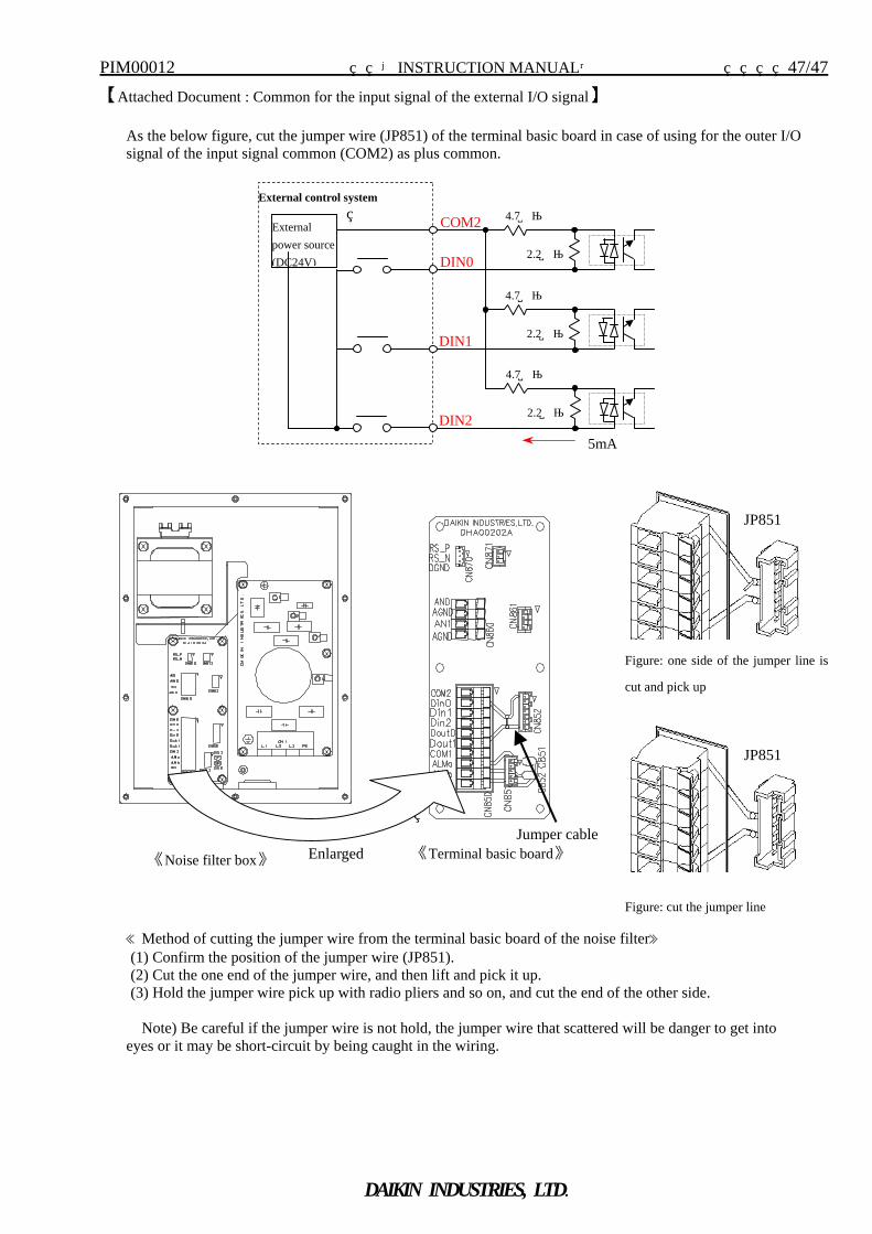
【Attached Document : Common for the input signal of the external I/O signal】
As the below figure, cut the jumper wire (JP851) of the terminal basic board in case of using for the outer I/O signal of the input signal common (COM2) as plus common.
≪Method of cutting the jumper wire from the terminal basic board of the noise filter≫ (1) Confirm the position of the jumper wire (JP851). (2) Cut the one end of the jumper wire, and then lift and pick it up. (3) Hold the jumper wire pick up with radio pliers and so on, and cut the end of the other side.
Note) Be careful if the jumper wire is not hold, the jumper wire that scattered will be danger to get into eyes or it may be short-circuit by being caught in the wiring.
Enlarged 《Terminal basic board》《Noise filter box》
Figure: one side of the jumper line is
cut and pick up
Figure: cut the jumper line
JP851
JP851
DIN2
4.7kΩ
2.2kΩ
4.7kΩ
2.2kΩ
4.7kΩ
2.2kΩ
COM2
DIN0
DIN1
External power source (DC24V)
External control system
5mA
Jumper cable