Embed Size (px)
Citation preview
K−2
K
HY
DR
AU
LIC P
OW
ER
UN
ITS
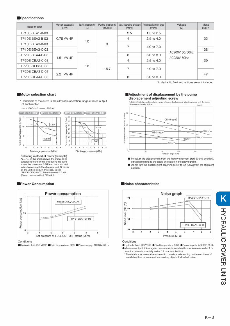
■Specifications
Base model
TP10E-BEA1-B-03
TP10E-BEA2-B-03
TP10E-BEA3-B-03
TP10E-BEA3-C-03
TP20E-BEA4-C-03
TP20E-CEA2-C-03
TP20E-CEB3-C-03
TP20E-CEA3-D-03
TP20E-CEA4-D-03
Tank capacity(L)
10
18
Max. operating pressure(MPa)
2.5
4
7
8
4
7
8
Motor capacity(kW)
0.75 kW 4P
1.5 kW 4P
2.2 kW 4P
8
16.7
Pump capacity(㎤/rev)
Pressure adjustment range(MPa)
1.5 to 2.5
2.5 to 4.0
4.0 to 7.0
6.0 to 8.0
2.5 to 4.0
4.0 to 7.0
6.0 to 8.0
Voltage(V)
AC200V 50/60Hz
AC220V 60Hz
Mass(kg)*1
33
38
39
47
*1: Hydraulic fluid and options are not included.
■Power Consumption ■Noise characteristics
■Adjustment of displacement by the pumpdisplacement adjusting screw
Conditions●Hydraulic fluid: ISO VG32 ●Fluid temperature: 50˚C ●Power supply: AC200V, 60 Hz
Conditions●Hydraulic fluid: ISO VG32 ●Fluid temperature: 50˚C ●Power supply: AC200V, 60 Hz●Measurement point: Average of measurements in 4 directions when measured at 1 m
from the device horizontally and at 1.2 m above the floor.* The data is a representative value which could vary depending on the conditions of
installation floor or frame and surrounding objects that reflect noise.
● To adjust the displacement from the factory shipment state (0-deg position), adjust it referring to the angle of rotation in the above graph.
● Do not turn the displacement adjusting screw to left (CCW) from the shipment position.
Relationship between the rotation angle of pump displacement adjusting screw and the pumpdisplacement under no load
CE-03 type
BE-03 type1800min-1
1800min-1
1500min-1
1500min-1
30
20
10
00 90 180 270 360 450
20mm2/c
Rotation angle (CW)
Dis
pla
cem
ent
und
er n
o lo
ad (L
/min
)
Selecting method of motor (example)As …*… in the graph shows, the motor to beselected is found in the area above the pointwhere the pressure 4.5 MPa on the horizontalaxis intersects with the displacement 17 L/minon the vertical axis. In this case, select“TP20E-CEA3-D-03” from the motor 2.2 kW(D) and pressure 4 to 7 MPa (A3).
TP20E−CEA*−D−03
TP*E−BEA*−C−03
TP20E−CEA4−D−3
TP20E−BEA4−C−3
Power consumption Noise graph
Pow
er c
onsu
mp
tion
(kW
)
Noi
se le
vel (
dB
(A))
Set pressure at FULL CUT-OFF status (MPa) Pressure (MPa)
■Motor selection chart
Discharge pressure (MPa)Discharge pressure (MPa)
Pum
p d
isch
arge
rat
e (L
/min
)
Pum
p d
isch
arge
rat
e (L
/min
)
* Underside of the curve is the allowable operation range at rated outputof each motor.
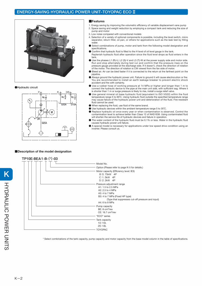
ENERGY-SAVING HYDRAULIC POWER UNIT-TOYOPAC ECO Ⅱ
■Features1. Energy saving by improving the volumetric efficiency of variable displacement vane pump2. Space saving and weight reduction by employing a compact tank and reducing the size of
pump and motor3. Low noise compared with conventional models4. Selection of a variety of optional components is possible, including the level switch, micro
separator, return filter, oil pan, or others for applications such as the leak test by filling water.
● Select combinations of pump, motor and tank from the following model designation and specifications.
● Confirm that hydraulic fluid is filled to the H level of oil level gauge in the tank.Replenish hydraulic fluid after operation since the fluid level drops as fluid enters in the tank.
● Use the phases L1 (R)-U, L2 (S)-V and L3 (T)-W at the power supply side and motor side. Run and stop alternately during test run and confirm that the pressure rises on the pressure gauge provided at the discharge side. If it doesn’t, check the direction of rotation of the motor. The direction of rotation is CW viewed from the fan side of motor.
● Bleed air. Air can be bled faster if it is connected to the return at the farthest point on the pipeline.
● Always ground the hydraulic power unit. Failure to ground it will cause electrocution or fire. You are recommended to install an earth leakage breaker to prevent electric shock accident and fire with certainty.
● Use a rubber hose of working pressure at 14 MPa or higher and longer than 1 m to connect the hydraulic device to the pipe at the main unit side, with sufficient sag. Where it is shorter than 1 m or surge pressure is likely to rise, install a surge relief valve.
● Use general mineral oil base hydraulic fluid (equivalent to ISO VG32) within the fluid temperature range 5 to 60˚C. Using hydraulic fluid outside the specified temperature range may cause failure of the hydraulic power unit and deterioration of the fluid. Fire-resistant fluid cannot be used.
● When replacing the fluid, use fluid of the same brand.● Use hydraulic devices within the ambient temperature range 5 to 35˚C. ● Replace hydraulic oil once every year or when contamination is observed. Control the
contamination level to achieve better than Class 12 of NAS1638. Using contaminated fluid will shorten the service life of hydraulic devices and failure in operation.
● The water content of the hydraulic fluid must be 0.1% or less. Water in the hydraulic fluid causes hydraulic power unit failure.
● A special model is necessary for applications under low speed drive condition using an inverter. Please consult us.
■Description of the model designation
TP10E-BEA1-B-(*)-03Model No.
Option (Please refer to page K-5 for details.)
Motor capacity (Efficiency level: IE3) B:0.75kW 4P C:1.5kW 4P D:2.2kW 4PPressure adjustment range A1: 1.5 to 2.5 MPa A2: 2.5 to 4 MPa A3: 4 to 7 MPa B3: 4 to 7 MPa (Fixed HP type) (Type that suppresses cut-off pressure and input) A4: 6 to 8 MPa
Pump capacity BE: 8 cm3/rev CE: 16.7 cm3/rev
“ECO” series
Tank capacity 10:10L 20:18LTOYOPAC
●Hydraulic circuit
* Select combinations of the tank capacity, pump capacity and motor capacity from the base model column in the table of specifications.
P R DR
K−3
K
HY
DR
AU
LIC P
OW
ER
UN
ITS
■Specifications
Base model
TP10E-BEA1-B-03
TP10E-BEA2-B-03
TP10E-BEA3-B-03
TP10E-BEA3-C-03
TP20E-BEA4-C-03
TP20E-CEA2-C-03
TP20E-CEB3-C-03
TP20E-CEA3-D-03
TP20E-CEA4-D-03
Tank capacity(L)
10
18
Max. operating pressure(MPa)
2.5
4
7
8
4
7
8
Motor capacity(kW)
0.75 kW 4P
1.5 kW 4P
2.2 kW 4P
8
16.7
Pump capacity(㎤/rev)
Pressure adjustment range(MPa)
1.5 to 2.5
2.5 to 4.0
4.0 to 7.0
6.0 to 8.0
2.5 to 4.0
4.0 to 7.0
6.0 to 8.0
Voltage(V)
AC200V 50/60Hz
AC220V 60Hz
Mass(kg)*1
33
38
39
47
*1: Hydraulic fluid and options are not included.
■Power Consumption ■Noise characteristics
■Adjustment of displacement by the pumpdisplacement adjusting screw
Conditions●Hydraulic fluid: ISO VG32 ●Fluid temperature: 50˚C ●Power supply: AC200V, 60 Hz
Conditions●Hydraulic fluid: ISO VG32 ●Fluid temperature: 50˚C ●Power supply: AC200V, 60 Hz●Measurement point: Average of measurements in 4 directions when measured at 1 m
from the device horizontally and at 1.2 m above the floor.* The data is a representative value which could vary depending on the conditions of
installation floor or frame and surrounding objects that reflect noise.
● To adjust the displacement from the factory shipment state (0-deg position), adjust it referring to the angle of rotation in the above graph.
● Do not turn the displacement adjusting screw to left (CCW) from the shipment position.
Relationship between the rotation angle of pump displacement adjusting screw and the pumpdisplacement under no load
CE-03 type
BE-03 type1800min-1
1800min-1
1500min-1
1500min-1
30
20
10
00 90 180 270 360 450
20mm2/c
Rotation angle (CW)
Dis
pla
cem
ent
und
er n
o lo
ad (L
/min
)
Selecting method of motor (example)As …*… in the graph shows, the motor to beselected is found in the area above the pointwhere the pressure 4.5 MPa on the horizontalaxis intersects with the displacement 17 L/minon the vertical axis. In this case, select“TP20E-CEA3-D-03” from the motor 2.2 kW(D) and pressure 4 to 7 MPa (A3).
TP20E−CEA*−D−03
TP*E−BEA*−C−03
TP20E−CEA4−D−3
TP20E−BEA4−C−3
Power consumption Noise graph
Pow
er c
onsu
mp
tion
(kW
)
Noi
se le
vel (
dB
(A))
Set pressure at FULL CUT-OFF status (MPa) Pressure (MPa)
■Motor selection chart
Discharge pressure (MPa)Discharge pressure (MPa)
Pum
p d
isch
arge
rat
e (L
/min
)
Pum
p d
isch
arge
rat
e (L
/min
)
* Underside of the curve is the allowable operation range at rated outputof each motor.
ENERGY-SAVING HYDRAULIC POWER UNIT-TOYOPAC ECO Ⅱ
■Features1. Energy saving by improving the volumetric efficiency of variable displacement vane pump2. Space saving and weight reduction by employing a compact tank and reducing the size of
pump and motor3. Low noise compared with conventional models4. Selection of a variety of optional components is possible, including the level switch, micro
separator, return filter, oil pan, or others for applications such as the leak test by filling water.
● Select combinations of pump, motor and tank from the following model designation and specifications.
● Confirm that hydraulic fluid is filled to the H level of oil level gauge in the tank.Replenish hydraulic fluid after operation since the fluid level drops as fluid enters in the tank.
● Use the phases L1 (R)-U, L2 (S)-V and L3 (T)-W at the power supply side and motor side. Run and stop alternately during test run and confirm that the pressure rises on the pressure gauge provided at the discharge side. If it doesn’t, check the direction of rotation of the motor. The direction of rotation is CW viewed from the fan side of motor.
● Bleed air. Air can be bled faster if it is connected to the return at the farthest point on the pipeline.
● Always ground the hydraulic power unit. Failure to ground it will cause electrocution or fire. You are recommended to install an earth leakage breaker to prevent electric shock accident and fire with certainty.
● Use a rubber hose of working pressure at 14 MPa or higher and longer than 1 m to connect the hydraulic device to the pipe at the main unit side, with sufficient sag. Where it is shorter than 1 m or surge pressure is likely to rise, install a surge relief valve.
● Use general mineral oil base hydraulic fluid (equivalent to ISO VG32) within the fluid temperature range 5 to 60˚C. Using hydraulic fluid outside the specified temperature range may cause failure of the hydraulic power unit and deterioration of the fluid. Fire-resistant fluid cannot be used.
● When replacing the fluid, use fluid of the same brand.● Use hydraulic devices within the ambient temperature range 5 to 35˚C. ● Replace hydraulic oil once every year or when contamination is observed. Control the
contamination level to achieve better than Class 12 of NAS1638. Using contaminated fluid will shorten the service life of hydraulic devices and failure in operation.
● The water content of the hydraulic fluid must be 0.1% or less. Water in the hydraulic fluid causes hydraulic power unit failure.
● A special model is necessary for applications under low speed drive condition using an inverter. Please consult us.
■Description of the model designation
TP10E-BEA1-B-(*)-03Model No.
Option (Please refer to page K-5 for details.)
Motor capacity (Efficiency level: IE3) B:0.75kW 4P C:1.5kW 4P D:2.2kW 4PPressure adjustment range A1: 1.5 to 2.5 MPa A2: 2.5 to 4 MPa A3: 4 to 7 MPa B3: 4 to 7 MPa (Fixed HP type) (Type that suppresses cut-off pressure and input) A4: 6 to 8 MPa
Pump capacity BE: 8 cm3/rev CE: 16.7 cm3/rev
“ECO” series
Tank capacity 10:10L 20:18LTOYOPAC
●Hydraulic circuit
* Select combinations of the tank capacity, pump capacity and motor capacity from the base model column in the table of specifications.
P R DR

K−4
K
HY
DR
AU
LIC P
OW
ER
UN
ITS
: With level switch
: With leak test by filling with water
: With micro separator
: With radiator filter
: With return filter
: With thermometer (TP20E only)
B
L
M
A
F
T
■Option model nomenclature
■Option device external dimensions (* in the fully equipped state. excluding manifold.)
TP10ETP20E-*EA*-*-(B)(L)(M)(A)(F)(T)(P)(G)(R)(D)(1)-03
TP10E-****-B-*-03 TP10E-****-C-*-03
TP20E-****-C-*-03 TP20E-****-D-*-03
E
F
E
F
: 1-station manifold: 2-station manifold: 3-station manifold
: Maintenance direction change
: With oil pan
: With oil level gauge cover
: With pressure switch
123
D
R
G
P
Op
tion
R
Op
tion
R
Model
TP20E-BEA4-C-03
TP20E-CEA2-C-03
TP20E-CEB3-C-03
TP20E-CEA3-D-03
TP20E-CEA4-D-03
A
181
181
181
191
191
B
(244)
(244)
(244)
(264)
(264)
C
(452)
(452)
(452)
(472)
(472)
D E F
(487)
(487)
(487)
(507)
(507)
460
460
460
485
485
480
480
480
505
505
Dimensions
(Unit: mm)
Part name
Tank
Strainer
TOYO pump
Pressure gauge
Oil filler port-and-air breather
Oil level gauge
Micro separator
Radiator
Nylon tube
Level switch
Return filter
Pressure switch
No
1
2
3
4
5
6
7
8
9
10
11
12
Part name
Tank
Strainer
TOYO pump
Pressure gauge
Oil filler port-and-air breather
Oil level gauge
Micro separator
Radiator
Nylon tube
Level switch
Return filter
Pressure switch
No
1
2
3
4
5
6
7
8
9
10
11
12
Model
TP10E-BEA1-B-03
TP10E-BEA2-B-03
TP10E-BEA3-B-03
TP10E-BEA3-C-03
A
171
171
171
181
B
(226)
(226)
(226)
(244)
C
(390)
(390)
(390)
(408)
D
(425)
(425)
(425)
(443)
E
430
430
430
460
F
450
450
450
480
Dimensions
(Unit: mm)
Option P
(12) Pressure switch
Option R
Option B
(10) Level switch
Option F
(11) Return filter
Option G
Oil level gaugeguard
Caution plate
Nameplate
Option G
Oil level gauge guard
Oil drain outlet (Rc3/8)
Pressure adjustment screw
HL
: Upper limit: Lower limit
(CW: Increases pressure.)Option A
Filter for radiator
Nameplate
Caution plate
Option D
Option D
Option L
Tank is tested withthe leak test by fillingwith water.
(5) Oil filler port-and-air breather
Op
tion
G
Op
tion
R
Op
tion
R
Op
tion
R
Option R
Oil pan
Option M
(7) Micro separator Option R
Option R
Option L
Tank test certificate
Op
tion
G
Option D
Op
tion
G
Displacement adjusting screw(CW: Reduces displacement)
Option P
(12) Pressure switch
Option R
Option B
(10) Level switch
Option F
(11) Return filter
Option G
Oil level gaugeguard
Caution plate
Nameplate
Option G
Oil level gauge guard
Oil drain outlet (Rc3/8)
Pressure adjustment screw(CW: Increases pressure.)
Option A
Filter for radiator
Nameplate
Caution plate
Option D
Option L
Tank is tested withthe leak test by fillingwith water.
(5) Oil filler port-and-air breather
Op
tion
G
Op
tion
T
Op
tion
R
Option R
Oil pan
Option M
(7) Micro separator Option R
Option R
Option L
Tank test certificate
Displacement adjusting screw(CW: Reduces displacement)
HL
: Upper limit: Lower limit
Option BCode (10) level switch “Opens” at 5 mm below the lower limit oflevel gauge.
Option BCode (10) level switch “Opens” at 5 mm below the lower limit oflevel gauge.
D direction
D direction
■Fluid temperature characteristics
■Outside dimensions
(6)L:下限 [9.3L]H:上限 [10L]
247
164
411
P:Rc1/2
R:Rc3/4
(9)ナイロンチューブ
(9)ナイロンチューブ
(5)注油口兼エアブリーザ
G3/4
銘 板
装置注意銘板
排油口(Rc3/8)
圧力調整ねじ(右回転圧力上昇)
DR:Rc1/2
吐出し量調整ねじ(右回転吐出し量減少)
250
300
345
360
※460(430)
165
4-∅9
315
67
4058
118
332
17.538.1Rc1/2
吐出し口
4-M8深12
(8)ラジエーター
(1)タンク
(7)マグネットプレート
(6)油圧計
(3)トヨポンプ
(4)圧力計
(2)ストレーナ
Pポート詳細
L:下限 [13.2L]H:上限 [18L]
P:Rc1/2
R:Rc3/4
(9)ナイロンチューブ
(9)ナイロンチューブ
(5)注油口兼エアブリーザ
G3/4
銘 板
(8)ラジエータ
(1)タンク
(7)マグネットプレート
装置注意銘板
排油口(Rc3/8)
圧力調整ねじ(右回転圧力上昇)
DR:Rc1/2
吐出し量調整ねじ(右回転吐出し量減少)
250
300
435
450
※485(460)
165
4-∅9
315
67
208
272
480
4058
118
332
17.5
38.1Rc1/2
吐出し口
4-M8深12
(6)油圧計
(3)トヨポンプ
(4)圧力計
(2)ストレーナ
Pポート詳細
Part name
Tank
Strainer
TOYO pump
Pressure gauge
Oil filler port-and air breather
Oil level gauge
Magnet plate
Radiator
Nylon tube
No
1
2
3
4
5
6
7
8
9
Part name
Tank
Strainer
TOYO pump
Pressure gauge
Oil filler port-and air breather
Oil level gauge
Magnet plate
Radiator
Nylon tube
No
1
2
3
4
5
6
7
8
9
* ( ) for TP10E-□□-B-03
* ( ) for TP20E-□□-C-03
TP10E-□□-B-03 [BASE MODEL]
TP10E-BEA3-B-03 TP20E-CEA3-D-03
TP10E-□□-C-03 [BASE MODEL]
TP20E-□□-C-03 [BASE MODEL] TP20E-□□-D-03 [BASE MODEL]
P R DR
P R DR
FC pressure 7 MPa FC pressure 5 MPa FC pressure 7 MPa FC pressure 5 MPa
Time (h) Time (h)
Flui
d t
emp
erat
ure
rise
(roo
m t
emp
erat
ure
diff
eren
ce) (
˚C)
Flui
d t
emp
erat
ure
rise
(roo
m t
emp
erat
ure
diff
eren
ce) (
˚C)
Conditions●Hydraulic fluid: ISO VG32 ●Fluid temperature: 35˚C ●Power supply: AC200V, 60 Hz● The data is obtained in windless condition with the discharge side of pump blocked, full cut-off (FC)
Caution●The data is a representative valve which could vary depending on constituting circuit devices and operation cycles.
Fluid temperature should be no higher than 60˚C.
(9) Nylon tube
(9) Nylon tube
*460 (430) (5) Oil filler port-and-air breather
(3) Toyo pump
(8) Radiator
G3/4
Nameplate
(1) Tank
Caution plate
(7) Magnet plate
(6) Hydraulic pressure gauge
Oil drain port (Rc3/8)
(2) Strainer
(2) strainer
(4) Pressure gauge
H: Upper limit [10 L]L: Lower limit [9.3 L]
Pressure adjustment screw(Cw: Increases pressure.)
Displacement adjusting screw(Cw: Reduces displacement pressure.)
Dischargeoutlet
4-M812 deep
P port detail
Dischargeoutlet
4-M812 deep
P port detail
(3) Toyo pump
(8) Radiator
G3/4
Nameplate
(1) Tank
Caution plate
(7) Magnet plate
(6) Hydraulic pressure gauge
Oil drain port (Rc3/8)
(4) Pressure gauge
H: Upper limit [18 L]L: Lower limit [9.3 L]
Pressure adjustment screw(Cw: Increases pressure.)
Displacement adjusting screw(Cw: Reduces displacement pressure.)
(9) Nylon tube
(9) Nylon tube
(5) Oil filler port-and-air breather*485 (460)

K−5
K
HY
DR
AU
LIC P
OW
ER
UN
ITS
: With level switch
: With leak test by filling with water
: With micro separator
: With radiator filter
: With return filter
: With thermometer (TP20E only)
B
L
M
A
F
T
■Option model nomenclature
■Option device external dimensions (* in the fully equipped state. excluding manifold.)
TP10ETP20E-*EA*-*-(B)(L)(M)(A)(F)(T)(P)(G)(R)(D)(1)-03
TP10E-****-B-*-03 TP10E-****-C-*-03
TP20E-****-C-*-03 TP20E-****-D-*-03
E
F
E
F
: 1-station manifold: 2-station manifold: 3-station manifold
: Maintenance direction change
: With oil pan
: With oil level gauge cover
: With pressure switch
123
D
R
G
P
Op
tion
R
Op
tion
R
Model
TP20E-BEA4-C-03
TP20E-CEA2-C-03
TP20E-CEB3-C-03
TP20E-CEA3-D-03
TP20E-CEA4-D-03
A
181
181
181
191
191
B
(244)
(244)
(244)
(264)
(264)
C
(452)
(452)
(452)
(472)
(472)
D E F
(487)
(487)
(487)
(507)
(507)
460
460
460
485
485
480
480
480
505
505
Dimensions
(Unit: mm)
Part name
Tank
Strainer
TOYO pump
Pressure gauge
Oil filler port-and-air breather
Oil level gauge
Micro separator
Radiator
Nylon tube
Level switch
Return filter
Pressure switch
No
1
2
3
4
5
6
7
8
9
10
11
12
Part name
Tank
Strainer
TOYO pump
Pressure gauge
Oil filler port-and-air breather
Oil level gauge
Micro separator
Radiator
Nylon tube
Level switch
Return filter
Pressure switch
No
1
2
3
4
5
6
7
8
9
10
11
12
Model
TP10E-BEA1-B-03
TP10E-BEA2-B-03
TP10E-BEA3-B-03
TP10E-BEA3-C-03
A
171
171
171
181
B
(226)
(226)
(226)
(244)
C
(390)
(390)
(390)
(408)
D
(425)
(425)
(425)
(443)
E
430
430
430
460
F
450
450
450
480
Dimensions
(Unit: mm)
Option P
(12) Pressure switch
Option R
Option B
(10) Level switch
Option F
(11) Return filter
Option G
Oil level gaugeguard
Caution plate
Nameplate
Option G
Oil level gauge guard
Oil drain outlet (Rc3/8)
Pressure adjustment screw
HL
: Upper limit: Lower limit
(CW: Increases pressure.)Option A
Filter for radiator
Nameplate
Caution plate
Option D
Option D
Option L
Tank is tested withthe leak test by fillingwith water.
(5) Oil filler port-and-air breather
Op
tion
G
Op
tion
R
Op
tion
R
Op
tion
R
Option R
Oil pan
Option M
(7) Micro separator Option R
Option R
Option L
Tank test certificateO
ptio
n G
Option D
Op
tion
G
Displacement adjusting screw(CW: Reduces displacement)
Option P
(12) Pressure switch
Option R
Option B
(10) Level switch
Option F
(11) Return filter
Option G
Oil level gaugeguard
Caution plate
Nameplate
Option G
Oil level gauge guard
Oil drain outlet (Rc3/8)
Pressure adjustment screw(CW: Increases pressure.)
Option A
Filter for radiator
Nameplate
Caution plate
Option D
Option L
Tank is tested withthe leak test by fillingwith water.
(5) Oil filler port-and-air breather
Op
tion
G
Op
tion
T
Op
tion
R
Option R
Oil pan
Option M
(7) Micro separator Option R
Option R
Option L
Tank test certificate
Displacement adjusting screw(CW: Reduces displacement)
HL
: Upper limit: Lower limit
Option BCode (10) level switch “Opens” at 5 mm below the lower limit oflevel gauge.
Option BCode (10) level switch “Opens” at 5 mm below the lower limit oflevel gauge.
D direction
D direction
■Fluid temperature characteristics
■Outside dimensions
(6)L:下限 [9.3L]H:上限 [10L]
247
164
411
P:Rc1/2
R:Rc3/4
(9)ナイロンチューブ
(9)ナイロンチューブ
(5)注油口兼エアブリーザ
G3/4
銘 板
装置注意銘板
排油口(Rc3/8)
圧力調整ねじ(右回転圧力上昇)
DR:Rc1/2
吐出し量調整ねじ(右回転吐出し量減少)
250
300
345
360
※460(430)
165
4-∅9
315
67
4058
118
332
17.5
38.1Rc1/2
吐出し口
4-M8深12
(8)ラジエーター
(1)タンク
(7)マグネットプレート
(6)油圧計
(3)トヨポンプ
(4)圧力計
(2)ストレーナ
Pポート詳細
L:下限 [13.2L]H:上限 [18L]
P:Rc1/2
R:Rc3/4
(9)ナイロンチューブ
(9)ナイロンチューブ
(5)注油口兼エアブリーザ
G3/4
銘 板
(8)ラジエータ
(1)タンク
(7)マグネットプレート
装置注意銘板
排油口(Rc3/8)
圧力調整ねじ(右回転圧力上昇)
DR:Rc1/2
吐出し量調整ねじ(右回転吐出し量減少)
250
300
435
450
※485(460)
165
4-∅9
315
67
208
272
480
4058
118
332
17.5
38.1Rc1/2
吐出し口
4-M8深12
(6)油圧計
(3)トヨポンプ
(4)圧力計
(2)ストレーナ
Pポート詳細
Part name
Tank
Strainer
TOYO pump
Pressure gauge
Oil filler port-and air breather
Oil level gauge
Magnet plate
Radiator
Nylon tube
No
1
2
3
4
5
6
7
8
9
Part name
Tank
Strainer
TOYO pump
Pressure gauge
Oil filler port-and air breather
Oil level gauge
Magnet plate
Radiator
Nylon tube
No
1
2
3
4
5
6
7
8
9
* ( ) for TP10E-□□-B-03
* ( ) for TP20E-□□-C-03
TP10E-□□-B-03 [BASE MODEL]
TP10E-BEA3-B-03 TP20E-CEA3-D-03
TP10E-□□-C-03 [BASE MODEL]
TP20E-□□-C-03 [BASE MODEL] TP20E-□□-D-03 [BASE MODEL]
P R DR
P R DR
FC pressure 7 MPa FC pressure 5 MPa FC pressure 7 MPa FC pressure 5 MPa
Time (h) Time (h)
Flui
d t
emp
erat
ure
rise
(roo
m t
emp
erat
ure
diff
eren
ce) (
˚C)
Flui
d t
emp
erat
ure
rise
(roo
m t
emp
erat
ure
diff
eren
ce) (
˚C)
Conditions●Hydraulic fluid: ISO VG32 ●Fluid temperature: 35˚C ●Power supply: AC200V, 60 Hz● The data is obtained in windless condition with the discharge side of pump blocked, full cut-off (FC)
Caution●The data is a representative valve which could vary depending on constituting circuit devices and operation cycles.
Fluid temperature should be no higher than 60˚C.
(9) Nylon tube
(9) Nylon tube
*460 (430) (5) Oil filler port-and-air breather
(3) Toyo pump
(8) Radiator
G3/4
Nameplate
(1) Tank
Caution plate
(7) Magnet plate
(6) Hydraulic pressure gauge
Oil drain port (Rc3/8)
(2) Strainer
(2) strainer
(4) Pressure gauge
H: Upper limit [10 L]L: Lower limit [9.3 L]
Pressure adjustment screw(Cw: Increases pressure.)
Displacement adjusting screw(Cw: Reduces displacement pressure.)
Dischargeoutlet
4-M812 deep
P port detail
Dischargeoutlet
4-M812 deep
P port detail
(3) Toyo pump
(8) Radiator
G3/4
Nameplate
(1) Tank
Caution plate
(7) Magnet plate
(6) Hydraulic pressure gauge
Oil drain port (Rc3/8)
(4) Pressure gauge
H: Upper limit [18 L]L: Lower limit [9.3 L]
Pressure adjustment screw(Cw: Increases pressure.)
Displacement adjusting screw(Cw: Reduces displacement pressure.)
(9) Nylon tube
(9) Nylon tube
(5) Oil filler port-and-air breather*485 (460)

K−6
K
HY
DR
AU
LIC P
OW
ER
UN
ITS
■Motor selection chart
■Specifications
Base model
TP10E-BEA2-B-*-3**
TP10E-BEA3-B-*-3**
TP10E-BEA3-C-*-3**
TP20E-BEA4-C-*-3**
TP20E-CEA2-C-*-3**
TP20E-CEB3-C-*-3**
TP20E-CEA3-D-*-3**
TP20E-CEA4-D-*-3**
Tank capacity(L)
10
18
Max. operating pressure(MPa)
4
7
8
4
7
8
Motor capacity(kW)
0.75kW 4P
1.5kW 4P
2.2kW 4P
8
16.7
Pump capacity(㎤/rev)
Pressure adjustment range(MPa)
2.5 to 4.0
4.0 to 7.0
6.0 to 8.0
2.0 to 4.0
4.0 to 7.0
6.0 to 8.0
Voltage(V)
China
AC200V/50Hz
AC380V/50Hz
AC220V/50Hz
Korea
AC220V/60Hz
AC440V/60Hz
AC380V/60Hz
Europe
AC200V/50Hz
AC380V/50Hz
AC400V/50Hz
Mass(㎏)*1
39
46
48
58
■Power consumption ■Noise characteristics
CE-* type
BE-* type1800min-1
1800min-1
1500min-1
1500min-1
30
20
10
00 90 180 270 360 450
20mm2/c
Conditions●Hydraulic fluid: ISO VG32 ●Fluid temperature: 50˚C ●Power supply: AC200 V, 60 Hz
Conditions●Hydraulic fluid: ISO VG32 ●Fluid temperature: 50˚C ●Power supply: AC200 V, 60 Hz●Measurement point: Average of measurements in 4 directions when measured at 1 m
from the device horizontally and at 1.2 m above the floor.* The data is a representative value which could vary depending on the conditions of
installation floor or frame and surrounding objects that reflect noise.
● To adjust the displacement from the factory shipment state (0-deg position), adjust it referring to the angle of rotation in the above graph.
● Do not turn the displacement adjusting screw to left (CCW) from the shipment position.
Selecting method of motor (example)As …*… in the graph shows, the motor to beselected is found in the area above the pointwhere the pressure 4.5 on the horizontal axisintersects with the displacement 17 L/min onthe vertical axis. In this case, select“TP20E-CEA3-D-03” from the motor 2.2 kW(D) and pressure 4 to 7 MPa (A3).
TP20E−CEA*−D−03**
TP20E−BEA*−C−3**
TP20E−CEA4−D−3**
TP20E−BEA4−C−3**
Power consumption
Pow
er c
onsu
mp
tion
(kW
)
Noi
se le
vel (
dB
(A))
Set pressure at FULL CUT-OFF status (MPa) Pressure (MPa)
■Adjustment of displacement by the pumpdisplacement adjusting screwRelationship between the rotation angle of pump displacement adjusting screw and the pumpdisplacement under no load
Rotation angle (CW)
Dis
pla
cem
ent
und
er n
o lo
ad (L
/min
)
Discharge pressure (MPa)Discharge pressure (MPa)
Pum
p d
isch
arge
rat
e (L
/min
)
Pum
p d
isch
arge
rat
e (L
/min
)
*1: Hydraulic fluid and options are not included.
* Underside of the curve is the allowable operation range at rated outputof each motor.
Noise graph
ENERGY-SAVING HYDRAULIC POWER UNIT COMPLIED WITH OVERSEAS STANDARDS-TOYOPAC ECO Ⅱ
■FeaturesThis energy-saving hydraulic unit is compliant to the regulations on the efficiency of low-pressure 3-phase induction motor, which are promoted in many countries over the world.・ Compliant to the high efficiency regulation, China・ Compliant to the high efficiency regulation, Korea・ Compliant to the high efficiency regulation, Europe
(TOYOPAC ECO II, page K-2, is also compliant to the specifications for Europe.)● Select combinations of pump, motor and tank from the following model designation and
specifications.● Confirm that hydraulic fluid is filled to the H level of oil level gauge in the tank.
Replenish hydraulic fluid after operation since the fluid level drops as fluid enters in the tank.
● Use the phases L1 (R)-U, L2 (S)-V and L3 (T)-W at the power supply side and motor side. Run and stop alternately during test run and confirm that the pressure rises on the pressure gauge provided at the discharge side. If it doesn’t, check the direction of rotation of the motor. The direction of rotation is CW viewed from the fan side of motor.
● Bleed air. Air can be bled faster if it is connected to the return at the farthest point on the pipeline.
● Always ground the hydraulic power unit. Failure to ground it will cause electric shock or fire. You are recommended to install an earth leakage breaker to prevent electric shock accident and fire with certainty.
● Use a rubber hose of working pressure at 14 MPa or higher and 2 to 3 meters in length to connect the hydraulic device to the pipe at the main unit side, with sufficient sag.
● Use general mineral oil base hydraulic fluid (equivalent to ISO VG32) within the fluid temperature range 5 to 60˚C. Using hydraulic fluid outside the specified temperature range may cause failure of the hydraulic power unit and deterioration of the fluid. Fire-resistant fluid cannot be used.
● When replacing the fluid, use fluid of the same brand.● Use hydraulic devices within the ambient temperature range 5 to 35˚C. ● Replace hydraulic oil once every year or when contamination is observed. Control the
contamination level to achieve better than Class 12 of NAS1638. Using contaminated fluid will shorten the service life of hydraulic devices and failure in operation.
● The water content of the hydraulic fluid must be 0.1% or less. Water in the hydraulic fluid causes hydraulic power unit failure.
■Description of the model designation
TP10E-BEA2-B-(B)(L)(M)-3NCCompliant to countries’ efficiency regulation Compliant to Chinese efficiency regulation Compliant to European efficiency regulation NC: AC200V, 50 Hz NN: AC200V, 50 Hz WC: AC380V, 50 Hz WN: AC380V, 50 Hz BC: AC220V, 50 Hz AC400V, 50 Hz Compliant to Korean efficiency regulation NK: AC220V, 60 Hz WK: AC440V, 60 Hz FK: AC380V, 60 Hz
Efficiency level: Motor compliant to IE3
Option M: With micro separator No code: With small magnet
Option L: Tested with the leak test by filling with water No code: Not tested
Option B: With level switch No code: Without level switch
TOYOPAC
Tank capacity 10: 10 L 20: 18 L
ECO series
Pump capacity BE: 8 cm3/rev
CE: 16.7 cm3/rev
Pressure adjustment range A2: 2.5 to 4 MPa
A3: 4 to 7 MPa A4: 6 to 8 MPa B3: 4 to 7 MPa
(Pump capacity “CE type” only)
Motor capacity B: 0.75 kW 4P C: 1.5 kW 4P D: 2.2 kW 4P
●Hydraulic circuit
* Select combinations of the tank capacity, pump capacity and motor capacity from the base model column in the table of specifications.
P R DR
Option

K−7
K
HY
DR
AU
LIC P
OW
ER
UN
ITS
■Motor selection chart
■Specifications
Base model
TP10E-BEA2-B-*-3**
TP10E-BEA3-B-*-3**
TP10E-BEA3-C-*-3**
TP20E-BEA4-C-*-3**
TP20E-CEA2-C-*-3**
TP20E-CEB3-C-*-3**
TP20E-CEA3-D-*-3**
TP20E-CEA4-D-*-3**
Tank capacity(L)
10
18
Max. operating pressure(MPa)
4
7
8
4
7
8
Motor capacity(kW)
0.75kW 4P
1.5kW 4P
2.2kW 4P
8
16.7
Pump capacity(㎤/rev)
Pressure adjustment range(MPa)
2.5 to 4.0
4.0 to 7.0
6.0 to 8.0
2.0 to 4.0
4.0 to 7.0
6.0 to 8.0
Voltage(V)
China
AC200V/50Hz
AC380V/50Hz
AC220V/50Hz
Korea
AC220V/60Hz
AC440V/60Hz
AC380V/60Hz
Europe
AC200V/50Hz
AC380V/50Hz
AC400V/50Hz
Mass(㎏)*1
39
46
48
58
■Power consumption ■Noise characteristics
CE-* type
BE-* type1800min-1
1800min-1
1500min-1
1500min-1
30
20
10
00 90 180 270 360 450
20mm2/c
Conditions●Hydraulic fluid: ISO VG32 ●Fluid temperature: 50˚C ●Power supply: AC200 V, 60 Hz
Conditions●Hydraulic fluid: ISO VG32 ●Fluid temperature: 50˚C ●Power supply: AC200 V, 60 Hz●Measurement point: Average of measurements in 4 directions when measured at 1 m
from the device horizontally and at 1.2 m above the floor.* The data is a representative value which could vary depending on the conditions of
installation floor or frame and surrounding objects that reflect noise.
● To adjust the displacement from the factory shipment state (0-deg position), adjust it referring to the angle of rotation in the above graph.
● Do not turn the displacement adjusting screw to left (CCW) from the shipment position.
Selecting method of motor (example)As …*… in the graph shows, the motor to beselected is found in the area above the pointwhere the pressure 4.5 on the horizontal axisintersects with the displacement 17 L/min onthe vertical axis. In this case, select“TP20E-CEA3-D-03” from the motor 2.2 kW(D) and pressure 4 to 7 MPa (A3).
TP20E−CEA*−D−03**
TP20E−BEA*−C−3**
TP20E−CEA4−D−3**
TP20E−BEA4−C−3**
Power consumption
Pow
er c
onsu
mp
tion
(kW
)
Noi
se le
vel (
dB
(A))
Set pressure at FULL CUT-OFF status (MPa) Pressure (MPa)
■Adjustment of displacement by the pumpdisplacement adjusting screwRelationship between the rotation angle of pump displacement adjusting screw and the pumpdisplacement under no load
Rotation angle (CW)
Dis
pla
cem
ent
und
er n
o lo
ad (L
/min
)
Discharge pressure (MPa)Discharge pressure (MPa)
Pum
p d
isch
arge
rat
e (L
/min
)
Pum
p d
isch
arge
rat
e (L
/min
)
*1: Hydraulic fluid and options are not included.
* Underside of the curve is the allowable operation range at rated outputof each motor.
Noise graph
ENERGY-SAVING HYDRAULIC POWER UNIT COMPLIED WITH OVERSEAS STANDARDS-TOYOPAC ECO Ⅱ
■FeaturesThis energy-saving hydraulic unit is compliant to the regulations on the efficiency of low-pressure 3-phase induction motor, which are promoted in many countries over the world.・ Compliant to the high efficiency regulation, China・ Compliant to the high efficiency regulation, Korea・ Compliant to the high efficiency regulation, Europe
(TOYOPAC ECO II, page K-2, is also compliant to the specifications for Europe.)● Select combinations of pump, motor and tank from the following model designation and
specifications.● Confirm that hydraulic fluid is filled to the H level of oil level gauge in the tank.
Replenish hydraulic fluid after operation since the fluid level drops as fluid enters in the tank.
● Use the phases L1 (R)-U, L2 (S)-V and L3 (T)-W at the power supply side and motor side. Run and stop alternately during test run and confirm that the pressure rises on the pressure gauge provided at the discharge side. If it doesn’t, check the direction of rotation of the motor. The direction of rotation is CW viewed from the fan side of motor.
● Bleed air. Air can be bled faster if it is connected to the return at the farthest point on the pipeline.
● Always ground the hydraulic power unit. Failure to ground it will cause electric shock or fire. You are recommended to install an earth leakage breaker to prevent electric shock accident and fire with certainty.
● Use a rubber hose of working pressure at 14 MPa or higher and 2 to 3 meters in length to connect the hydraulic device to the pipe at the main unit side, with sufficient sag.
● Use general mineral oil base hydraulic fluid (equivalent to ISO VG32) within the fluid temperature range 5 to 60˚C. Using hydraulic fluid outside the specified temperature range may cause failure of the hydraulic power unit and deterioration of the fluid. Fire-resistant fluid cannot be used.
● When replacing the fluid, use fluid of the same brand.● Use hydraulic devices within the ambient temperature range 5 to 35˚C. ● Replace hydraulic oil once every year or when contamination is observed. Control the
contamination level to achieve better than Class 12 of NAS1638. Using contaminated fluid will shorten the service life of hydraulic devices and failure in operation.
● The water content of the hydraulic fluid must be 0.1% or less. Water in the hydraulic fluid causes hydraulic power unit failure.
■Description of the model designation
TP10E-BEA2-B-(B)(L)(M)-3NCCompliant to countries’ efficiency regulation Compliant to Chinese efficiency regulation Compliant to European efficiency regulation NC: AC200V, 50 Hz NN: AC200V, 50 Hz WC: AC380V, 50 Hz WN: AC380V, 50 Hz BC: AC220V, 50 Hz AC400V, 50 Hz Compliant to Korean efficiency regulation NK: AC220V, 60 Hz WK: AC440V, 60 Hz FK: AC380V, 60 Hz
Efficiency level: Motor compliant to IE3
Option M: With micro separator No code: With small magnet
Option L: Tested with the leak test by filling with water No code: Not tested
Option B: With level switch No code: Without level switch
TOYOPAC
Tank capacity 10: 10 L 20: 18 L
ECO series
Pump capacity BE: 8 cm3/rev
CE: 16.7 cm3/rev
Pressure adjustment range A2: 2.5 to 4 MPa
A3: 4 to 7 MPa A4: 6 to 8 MPa B3: 4 to 7 MPa
(Pump capacity “CE type” only)
Motor capacity B: 0.75 kW 4P C: 1.5 kW 4P D: 2.2 kW 4P
●Hydraulic circuit
* Select combinations of the tank capacity, pump capacity and motor capacity from the base model column in the table of specifications.
P R DR
Option

K−8
K
HY
DR
AU
LIC P
OW
ER
UN
ITS
TP20E-****-C-*-3**
TP20E-****-D-*-3**
Model
TP20E-BEA4-C-*-3**
TP20E-CEA2-C-*-3**
TP20E-CEB3-C-*-3**
TP20E-CEA3-D-*-3**
TP20E-CEA4-D-*-3**
A
485
485
485
500
500
B
192
192
192
200
200
C
223
223
223
242
242
D
431
431
431
450
450
Dimensions
Unit: mm
Part name
Oil level gauge
Micro separator
Radiator
Nylon tube
Level switch
No
6
7
8
9
10
Part name
Tank
Strainer
TOYO pump
Pressure gauge
Oil filler port-and-air breather
No
1
2
3
4
5
MODEL
MFG.NO.
HBPV-3
-VB1E-14A
TOYOOKI KOGYO
豊興工業株式会社
Rotation
回転方向
CO., LTD.
(9A)
(9B)
Option LTank test certificate
Option B(10) level switch
150
315
332
A
58
67
118
DR: Rc1/2
40
P: Rc1/2
R: Rc3/4Micro separator for(7) magnetoption M
(5) Oil filler port-and-air breather
Seal nameplate(Toyo pump part)
M10 eyebolt hole
(3)
(4)
(6)
(1)
(8)
410
435
450
B
Nameplate
Caution plateOil drain port (Rc3/8)
Cable entrance ∅27
I NO U T
(2)
25 250 25
300
208
D
332
C
Pressure adjustment screw(CW: Increases pressure.)
Displacement adjusting screw(CW: Reduces displacement)
4-∅9
HL
: Upper limit: Lower limit
Option BCode (10) level switch “opens” at 5 mm below lowerlimit of lelve gauge.
■Fluid temperature characteristics
■Outside dimensions of option device (* In the fully equipped state)
TP10E-****-B-*-3**
TP10E-****-C-*-3**
Model
TP10E-BEA2-B-*-3**
TP10E-BEA3-B-*-3**
TP10E-BEA3-C-*-3**
A
435
435
480.5
B
184
184
192
C
204
204
223
D
368
368
387
Dimensions
Unit: mmPart name
Oil level gauge
Micro separator
Radiator
Nylon tube
Level switch
No
6
7
8
9
10
Part name
Tank
Strainer
TOYO pump
Pressure gauge
Oil filler port-and-air breather
No
1
2
3
4
5
TP10E-BEA3-B-03** TP20E-CEA3-D-03**
Conditions: ● Hydraulic fluid: ISO VG32 ● Fluid temperature: 35˚C ● Power supply: AC200V, 60 Hz● The data is obtained in windless condition with discharge side of pump blocked, full cut-off (FC).
Caution: ● The data is a representative valve which could vary depending on constituting circuit devices and operation cycles.Fluid temperature should be no higher than 60˚C.
Time (h)
Flui
d te
mpe
ratu
re ri
se(ro
om te
mpe
ratu
re d
iffer
ence
) (˚C
)
Time (h)
Flui
d te
mpe
ratu
re ri
se(ro
om te
mpe
ratu
re d
iffer
ence
) (˚C
)
FC pressure 7 MPa FC pressure 5 MPa FC pressure 7 MPa FC pressure 5 MPa
(3)
(4)
(1)
(6)
(8)
320
345
360
B
Cable entrance ∅27
Oil drain port (Rc3/8)
Nameplate
Caution plate
I NO U T
(2)
D
164
25025 25
300
(198)
4-∅9
332
C
Pressure adjustment screw(CW: Increases pressure.)
Displacement adjusting screw(CW: Reduces displacement)
MODEL
MFG.NO.
HBPV-3
-VB1E-14A
TOYOOKI KOGYO
豊興工業株式会社
Rotation
回転方向
CO., LTD.
Option B(10) level switch
Option LTank test certificate
(9B)
(9A) 150
332
A
315
(5) Oil filler port-and-air breather
58
67
118
R: Rc3/4
P: Rc1/2Micro separator for(7) magnetoption M
40
Seal nameplate(Toyo pump part)
M10 eyebolt hole
DR: Rc1/2
Option BCode (10) level switch “opens” at 5 mm below lowerlimit of lelve gauge.
HL
: Upper limit: Lower limit

K−9
K
HY
DR
AU
LIC P
OW
ER
UN
ITSTP20E-****-C-*-3**
TP20E-****-D-*-3**
Model
TP20E-BEA4-C-*-3**
TP20E-CEA2-C-*-3**
TP20E-CEB3-C-*-3**
TP20E-CEA3-D-*-3**
TP20E-CEA4-D-*-3**
A
485
485
485
500
500
B
192
192
192
200
200
C
223
223
223
242
242
D
431
431
431
450
450
Dimensions
Unit: mm
Part name
Oil level gauge
Micro separator
Radiator
Nylon tube
Level switch
No
6
7
8
9
10
Part name
Tank
Strainer
TOYO pump
Pressure gauge
Oil filler port-and-air breather
No
1
2
3
4
5
MODEL
MFG.NO.
HBPV-3
-VB1E-14A
TOYOOKI KOGYO
豊興工業株式会社
Rotation
回転方向
CO., LTD.
(9A)
(9B)
Option LTank test certificate
Option B(10) level switch
150
315
332
A
58
67
118
DR: Rc1/2
40
P: Rc1/2
R: Rc3/4Micro separator for(7) magnetoption M
(5) Oil filler port-and-air breather
Seal nameplate(Toyo pump part)
M10 eyebolt hole
(3)
(4)
(6)
(1)
(8)
410
435
450
B
Nameplate
Caution plateOil drain port (Rc3/8)
Cable entrance ∅27
I NO U T
(2)
25 250 25
300
208
D
332
C
Pressure adjustment screw(CW: Increases pressure.)
Displacement adjusting screw(CW: Reduces displacement)
4-∅9
HL
: Upper limit: Lower limit
Option BCode (10) level switch “opens” at 5 mm below lowerlimit of lelve gauge.
■Fluid temperature characteristics
■Outside dimensions of option device (* In the fully equipped state)
TP10E-****-B-*-3**
TP10E-****-C-*-3**
Model
TP10E-BEA2-B-*-3**
TP10E-BEA3-B-*-3**
TP10E-BEA3-C-*-3**
A
435
435
480.5
B
184
184
192
C
204
204
223
D
368
368
387
Dimensions
Unit: mmPart name
Oil level gauge
Micro separator
Radiator
Nylon tube
Level switch
No
6
7
8
9
10
Part name
Tank
Strainer
TOYO pump
Pressure gauge
Oil filler port-and-air breather
No
1
2
3
4
5
TP10E-BEA3-B-03** TP20E-CEA3-D-03**
Conditions: ● Hydraulic fluid: ISO VG32 ● Fluid temperature: 35˚C ● Power supply: AC200V, 60 Hz● The data is obtained in windless condition with discharge side of pump blocked, full cut-off (FC).
Caution: ● The data is a representative valve which could vary depending on constituting circuit devices and operation cycles.Fluid temperature should be no higher than 60˚C.
Time (h)
Flui
d te
mpe
ratu
re ri
se(ro
om te
mpe
ratu
re d
iffer
ence
) (˚C
)
Time (h)
Flui
d te
mpe
ratu
re ri
se(ro
om te
mpe
ratu
re d
iffer
ence
) (˚C
)
FC pressure 7 MPa FC pressure 5 MPa FC pressure 7 MPa FC pressure 5 MPa
(3)
(4)
(1)
(6)
(8)
320
345
360
B
Cable entrance ∅27
Oil drain port (Rc3/8)
Nameplate
Caution plate
I NO U T
(2)
D
164
25025 25
300
(198)
4-∅9
332
C
Pressure adjustment screw(CW: Increases pressure.)
Displacement adjusting screw(CW: Reduces displacement)
MODEL
MFG.NO.
HBPV-3
-VB1E-14A
TOYOOKI KOGYO
豊興工業株式会社
Rotation
回転方向
CO., LTD.
Option B(10) level switch
Option LTank test certificate
(9B)
(9A) 150
332
A
315
(5) Oil filler port-and-air breather
58
67
118
R: Rc3/4
P: Rc1/2Micro separator for(7) magnetoption M
40
Seal nameplate(Toyo pump part)
M10 eyebolt hole
DR: Rc1/2
Option BCode (10) level switch “opens” at 5 mm below lowerlimit of lelve gauge.
HL
: Upper limit: Lower limit