Embed Size (px)
DESCRIPTION
Manual de usuario
Citation preview

New Waste Heat Recovery System– challenges and solutions
Heimdal New Power Generator Project
Prepared by: Hydro: Unn Orstein, Project manager
Knuth Jahr, Mechanical Disipline LeadReinertsen: Morten Kongelf, Mechanical Discipline Lead
Petroleumstilsynet Seminar – exhaust stacks and waste heat recovery2007-02-07
• Page: 2 •
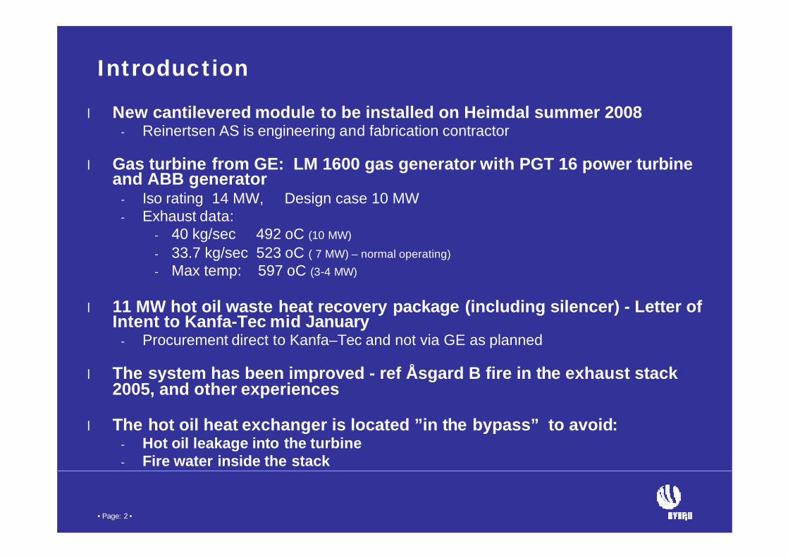
Introduction
l New cantilevered module to be installed on Heimdal summer 2008- Reinertsen AS is engineering and fabrication contractor
l Gas turbine from GE: LM 1600 gas generator with PGT 16 power turbineand ABB generator
- Iso rating 14 MW, Design case 10 MW- Exhaust data:
- 40 kg/sec 492 oC (10 MW)
- 33.7 kg/sec 523 oC ( 7 MW) – normal operating)- Max temp: 597 oC (3-4 MW)
l 11 MW hot oil waste heat recovery package (including silencer) - Letter ofIntent to Kanfa-Tec mid January
- Procurement direct to Kanfa–Tec and not via GE as planned
l The system has been improved - ref Åsgard B fire in the exhaust stack2005, and other experiences
l The hot oil heat exchanger is located ”in the bypass” to avoid:- Hot oil leakage into the turbine- Fire water inside the stack

• Page: 3 •
WHRU - hot oil systems - challenges
l Leakage from tube bundle in traditional vertical exhaust stack- Accumulates in bellows – textile a special problem- Tube rupture can result in > 3 M3 drainage to the turbine collector- Fire - due to oxygen in the exhaust, air during rundown of turbine and the
chimney effect
l Detect the hydrocarbon in the exhaust before the fire starts
l Drainage of hot oil
l Fire fighting system
l Damage to turbine and turbine casing due to fire and water
l Leakage from flanges in the hot oil piping hitting warm surfaces

• Page: 4 •
Alternative configurations evaluated
l Traditional configurationwith WHRU above theturbine exhaust outlet
l WHRU in the bypass stream
Silencer not shown
Exhaust Exhaust
Silencer shown partlyDrawings & photo from Kanfa-Tec

• Page: 5 •
Main issues in case of hot oil leakage
l Sump to collect hot oil leakage- Separate tank not shown on figure, 3 m3
l Detect liquid in sump- Drain test valve- Level indication
l Bellows should avoid:- small hot oil leakage into the exhaust
stream to collect in the textile and ignite
In case of leakage:- Close the louver (shut off air flow)- Nitrogen to inert the volume?- Drain the bundle to recovery tank- Fire water monitor on the LQ roof
Ideas:- Detection of hydrocarbon in exhaust?- Separate the 2 exhaust stream to avoid bellows?

• Page: 6 •
Material selection
l Ducting: AISI 321- Max operating temperature is 597 0C at 25 oC ambient - WHRU Supplier recommend design temperature of 593 oC
- Ambient temperature is normally well below the 25 oC- Max operating temperature is a transient case and not a normal operating case- Due to cooling of the outside of the duct- Duct downstream the bundle is exposed to lower exhaust temperature
- AISI 321 is the standard material for GE Energy LM1600 Exhaust Collector.
l Heatexchanger tube bundle/fins: ASTM A 106 GrB

• Page: 7 •
Duct leakages
l Design changes to reduce vibrations- avoid fatigue
- Rounded corners- Minimum temperature gradients- Avoid lifting ears or other additional
structures- reduced swirls
- LM 1600 has trippel diffusers in the Exhaust Collector
l Improved bolt design- Thermobolt has been specified- Bolt does not loose pre-tension during
turbine start cycle - Lover loads on bolts- Controlled compression loads on gasket

• Page: 8 •
Reduce potential for hot oil leakage from WHRU heat exchanger
l Improved bundle support- Avoid U-clamps interfering with the tubes- Possible tube contacts with screw, bolts etc is avoided
l Inspection of support of tube bundle during assembly
l The deck structure to be designed to reduce WHRU casing deflection

• Page: 9 •
Leakage from hot oil piping
l The following has been specified:- The hot oil/supply and return lines shall be welded to the WHRU
l Flanges are minimized and located away from hot surfaces

• Page: 10 •
Valve comparison
Louver – selected
Prol Smoother regulation in almost
closed position- Improved temperature control
l Improved flow distributionl Lower torque and material stressesl Pneumatic control system
Conl Leakage rate is 0.04 %l Pressure loss is higher – not critcall More moving parts
Flap (new type used on Grane)
Prol Improved sealing to avoid
oveheating the oil/cracking- Leakage rate 0.02 %
l Grane experience is positive
Conl Hydraulic control is required due to
high torque requiredl More expensivel Higher weight

• Page: 11 •
2 separate exhaust outlets - idea
Prol Avoid potential small hot oil leakage
into the exhaust to collect in thetextile in the bellow
l Reduce maintenance- Remove 2 bellows- Simplify removal of silencer and bundle
l Reduce weight
Conl The reduced velocity in case of part
load will have effect on dispersion Note: Turbine has excess power and a restriction in the outlet to increaseflow is possible
• Page: 12 •
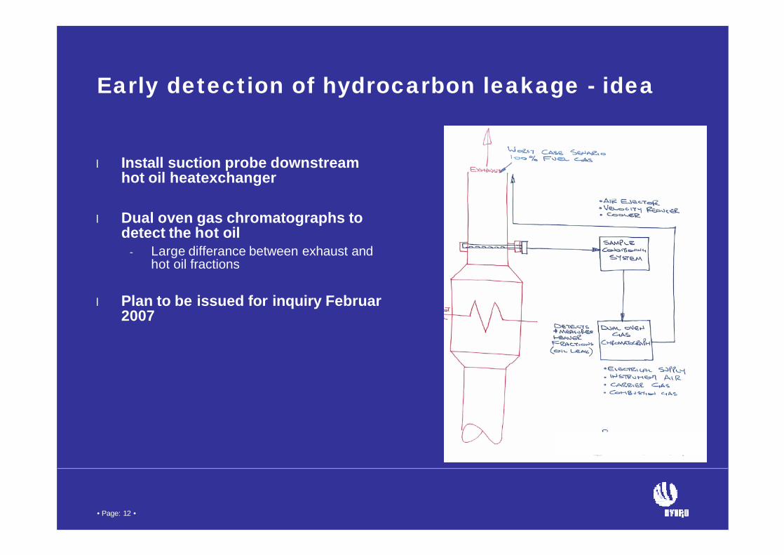
Early detection of hydrocarbon leakage - idea
l Install suction probe downstreamhot oil heatexchanger
l Dual oven gas chromatographs to detect the hot oil
- Large differance between exhaust and hot oil fractions
l Plan to be issued for inquiry Februar 2007
• Page: 13 •