Embed Size (px)
Citation preview
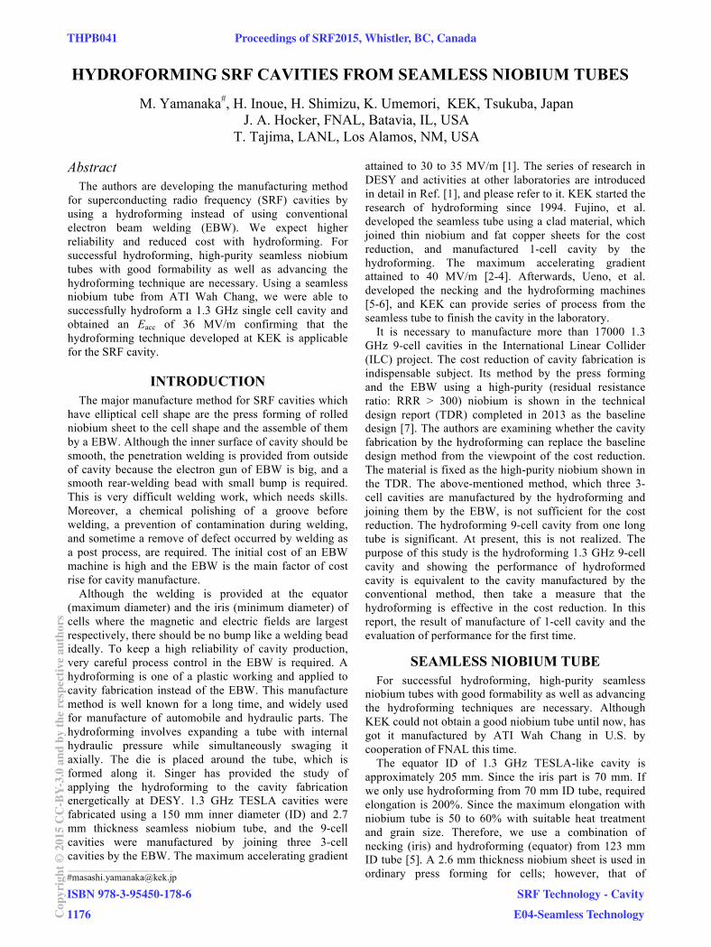
HYDROFORMING SRF CAVITIES FROM SEAMLESS NIOBIUM TUBES
M. Yamanaka#, H. Inoue, H. Shimizu, K. Umemori, KEK, Tsukuba, Japan
J. A. Hocker, FNAL, Batavia, IL, USA
T. Tajima, LANL, Los Alamos, NM, USA
Abstract
The authors are developing the manufacturing method
for superconducting radio frequency (SRF) cavities by
using a hydroforming instead of using conventional
electron beam welding (EBW). We expect higher
reliability and reduced cost with hydroforming. For
successful hydroforming, high-purity seamless niobium
tubes with good formability as well as advancing the
hydroforming technique are necessary. Using a seamless
niobium tube from ATI Wah Chang, we were able to
successfully hydroform a 1.3 GHz single cell cavity and
obtained an Eacc of 36 MV/m confirming that the
hydroforming technique developed at KEK is applicable
for the SRF cavity.
INTRODUCTION
The major manufacture method for SRF cavities which
have elliptical cell shape are the press forming of rolled
niobium sheet to the cell shape and the assemble of them
by a EBW. Although the inner surface of cavity should be
smooth, the penetration welding is provided from outside
of cavity because the electron gun of EBW is big, and a
smooth rear-welding bead with small bump is required.
This is very difficult welding work, which needs skills.
Moreover, a chemical polishing of a groove before
welding, a prevention of contamination during welding,
and sometime a remove of defect occurred by welding as
a post process, are required. The initial cost of an EBW
machine is high and the EBW is the main factor of cost
rise for cavity manufacture.
Although the welding is provided at the equator
(maximum diameter) and the iris (minimum diameter) of
cells where the magnetic and electric fields are largest
respectively, there should be no bump like a welding bead
ideally. To keep a high reliability of cavity production,
very careful process control in the EBW is required. A
hydroforming is one of a plastic working and applied to
cavity fabrication instead of the EBW. This manufacture
method is well known for a long time, and widely used
for manufacture of automobile and hydraulic parts. The
hydroforming involves expanding a tube with internal
hydraulic pressure while simultaneously swaging it
axially. The die is placed around the tube, which is
formed along it. Singer has provided the study of
applying the hydroforming to the cavity fabrication
energetically at DESY. 1.3 GHz TESLA cavities were
fabricated using a 150 mm inner diameter (ID) and 2.7
mm thickness seamless niobium tube, and the 9-cell
cavities were manufactured by joining three 3-cell
cavities by the EBW. The maximum accelerating gradient
attained to 30 to 35 MV/m [1]. The series of research in
DESY and activities at other laboratories are introduced
in detail in Ref. [1], and please refer to it. KEK started the
research of hydroforming since 1994. Fujino, et al.
developed the seamless tube using a clad material, which
joined thin niobium and fat copper sheets for the cost
reduction, and manufactured 1-cell cavity by the
hydroforming. The maximum accelerating gradient
attained to 40 MV/m [2-4]. Afterwards, Ueno, et al.
developed the necking and the hydroforming machines
[5-6], and KEK can provide series of process from the
seamless tube to finish the cavity in the laboratory.
It is necessary to manufacture more than 17000 1.3
GHz 9-cell cavities in the International Linear Collider
(ILC) project. The cost reduction of cavity fabrication is
indispensable subject. Its method by the press forming
and the EBW using a high-purity (residual resistance
ratio: RRR > 300) niobium is shown in the technical
design report (TDR) completed in 2013 as the baseline
design [7]. The authors are examining whether the cavity
fabrication by the hydroforming can replace the baseline
design method from the viewpoint of the cost reduction.
The material is fixed as the high-purity niobium shown in
the TDR. The above-mentioned method, which three 3-
cell cavities are manufactured by the hydroforming and
joining them by the EBW, is not sufficient for the cost
reduction. The hydroforming 9-cell cavity from one long
tube is significant. At present, this is not realized. The
purpose of this study is the hydroforming 1.3 GHz 9-cell
cavity and showing the performance of hydroformed
cavity is equivalent to the cavity manufactured by the
conventional method, then take a measure that the
hydroforming is effective in the cost reduction. In this
report, the result of manufacture of 1-cell cavity and the
evaluation of performance for the first time.
SEAMLESS NIOBIUM TUBE
For successful hydroforming, high-purity seamless
niobium tubes with good formability as well as advancing
the hydroforming techniques are necessary. Although
KEK could not obtain a good niobium tube until now, has
got it manufactured by ATI Wah Chang in U.S. by
cooperation of FNAL this time.
The equator ID of 1.3 GHz TESLA-like cavity is
approximately 205 mm. Since the iris part is 70 mm. If
we only use hydroforming from 70 mm ID tube, required
elongation is 200%. Since the maximum elongation with
niobium tube is 50 to 60% with suitable heat treatment
and grain size. Therefore, we use a combination of
necking (iris) and hydroforming (equator) from 123 mm
ID tube [5]. A 2.6 mm thickness niobium sheet is used in
ordinary press forming for cells; however, that of ____________________________________________
THPB041 Proceedings of SRF2015, Whistler, BC, Canada
ISBN 978-3-95450-178-6
1176Cop
yrig
ht©
2015
CC
-BY-
3.0
and
byth
ere
spec
tive
auth
ors
SRF Technology - Cavity
E04-Seamless Technology
seamless tube is set to 3.5 mm, a little largely. Because
the thickness at the equator part is expected to become
thin by hydroforming, the thickness of the tube is
increased to secure 2.6 mm there. The tube length
required for 1-cell cavity is 450 mm. It contains the length
of the portion chucked by the processing machine. The
beam pipes joined to both ends of cavity by EBW is
separate part, and not included in above length. The tube
length for 3-cell and the 9-cell cavities are 800 mm and
1700 mm, respectively in the same manner. The RRR of
niobium ingot, which is the start material of this tube, is
387. The hardness of the tube as received from the builder
is 46 HV.
MANUFACTURE OF CAVITY
Necking and Hydroforming
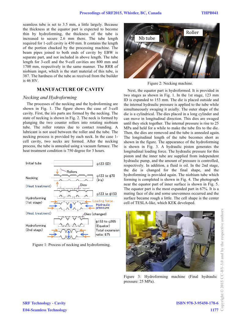
The processes of the necking and the hydroforming are
shown in Fig. 1. The figure shows the case of 3-cell
cavity. First, the iris parts are formed by the necking. The
state of necking is shown in Fig. 2. The neck is formed by
plunging the two counter rollers into rotating niobium
tube. The roller rotates due to contact rounding. A
lubricant is not used between the roller and the tube. The
necking process is provided by each neck. In the case 1-
cell cavity, two necks are formed. After the necking
process, the tube is annealed using a vacuum furnace. The
heat treatment condition is 750 degree for 3 hours.
Figure 1: Process of necking and hydroforming.
Figure 2: Necking machine.
Next, the equator part is hydroformed. It is provided in
two stages as shown in Fig. 1. In the 1st stage, 123 mm
ID is expanded to 153 mm. The die is placed outside and
the internal hydraulic pressure is applied to the tube while
simultaneously swaging it axially. The outer shape of the
die is a cylindrical. The dies placed in a long cylinder and
can move in longitudinal direction. This dies are swaged
until they stick together. The internal pressure is rise to 25
MPa and held for a while to make the tube fits to the die.
Then, the dies are removed and the tube is annealed again.
The longitudinal length of the tube becomes short as
shown in the figure. The appearance of the hydroforming
is shown in Fig. 3. A hydraulic piston generates the
longitudinal loading force. The hydraulic pressure for this
piston and the inner tube are supplied from independent
hydraulic pump, and the amount of pressure is controlled,
respectively. In addition, a fluid is oil. In the 2nd stage,
the die is changed for the final shape, and the
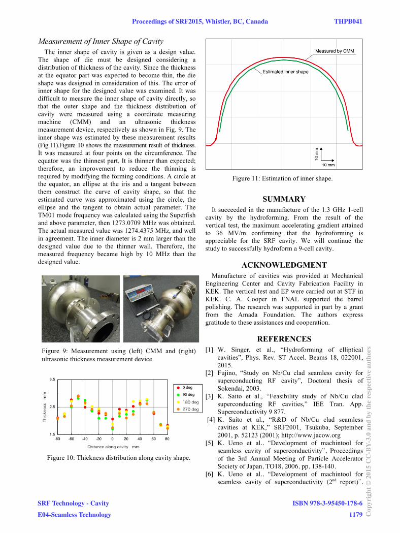
hydroforming is provided again. The niobium tube which
forming is completed is shown in Fig. 4. The photograph
near the equator part of inner surface is shown in Fig. 5.
The equator part is the most expanded part in 67%. It is a
mating face of die and some unevenness occurred and the
surface became rough a little. The cell shape is the center
cell of TESLA-like, which KEK developed.
Figure 3: Hydroforming machine (Final hydraulic
pressure: 25 MPa).
Nb tube
Roller
Proceedings of SRF2015, Whistler, BC, Canada THPB041
SRF Technology - Cavity
E04-Seamless Technology
ISBN 978-3-95450-178-6
1177 Cop
yrig
ht©
2015
CC
-BY-
3.0
and
byth
ere
spec
tive
auth
ors
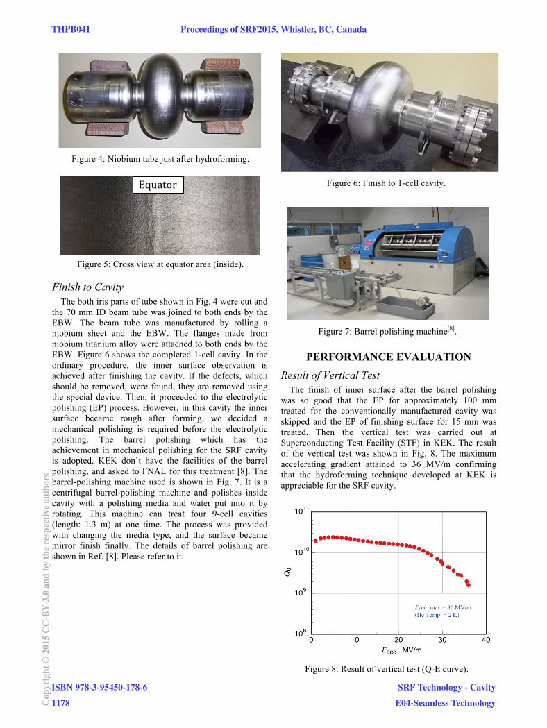
Figure 4: Niobium tube just after hydroforming.
Figure 5: Cross view at equator area (inside).
Finish to Cavity
The both iris parts of tube shown in Fig. 4 were cut and
the 70 mm ID beam tube was joined to both ends by the
EBW. The beam tube was manufactured by rolling a
niobium sheet and the EBW. The flanges made from
niobium titanium alloy were attached to both ends by the
EBW. Figure 6 shows the completed 1-cell cavity. In the
ordinary procedure, the inner surface observation is
achieved after finishing the cavity. If the defects, which
should be removed, were found, they are removed using
the special device. Then, it proceeded to the electrolytic
polishing (EP) process. However, in this cavity the inner
surface became rough after forming, we decided a
mechanical polishing is required before the electrolytic
polishing. The barrel polishing which has the
achievement in mechanical polishing for the SRF cavity
is adopted. KEK don’t have the facilities of the barrel
polishing, and asked to FNAL for this treatment [8]. The
barrel-polishing machine used is shown in Fig. 7. It is a
centrifugal barrel-polishing machine and polishes inside
cavity with a polishing media and water put into it by
rotating. This machine can treat four 9-cell cavities
(length: 1.3 m) at one time. The process was provided
with changing the media type, and the surface became
mirror finish finally. The details of barrel polishing are
shown in Ref. [8]. Please refer to it.
Figure 6: Finish to 1-cell cavity.
Figure 7: Barrel polishing machine[8]
.
PERFORMANCE EVALUATION
Result of Vertical Test
The finish of inner surface after the barrel polishing
was so good that the EP for approximately 100 mm
treated for the conventionally manufactured cavity was
skipped and the EP of finishing surface for 15 mm was
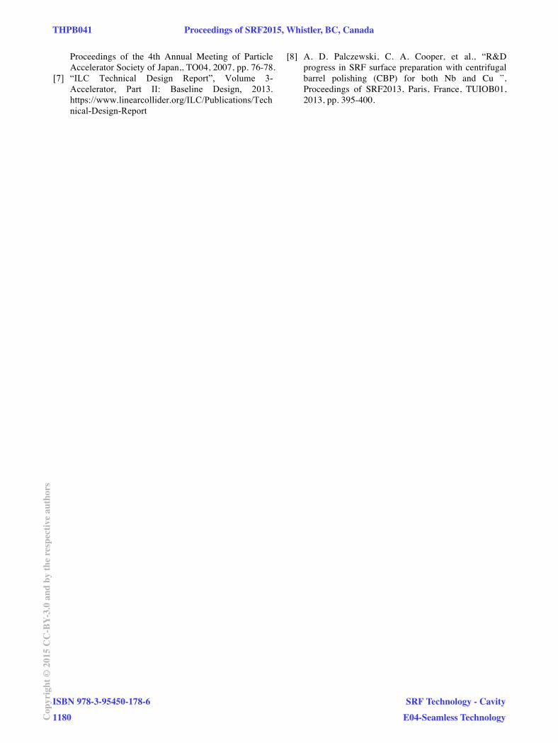
treated. Then the vertical test was carried out at
Superconducting Test Facility (STF) in KEK. The result
of the vertical test was shown in Fig. 8. The maximum
accelerating gradient attained to 36 MV/m confirming
that the hydroforming technique developed at KEK is
appreciable for the SRF cavity.
Figure 8: Result of vertical test (Q-E curve).
Equator
THPB041 Proceedings of SRF2015, Whistler, BC, Canada
ISBN 978-3-95450-178-6
1178Cop
yrig
ht©
2015
CC
-BY-
3.0
and
byth
ere
spec
tive
auth
ors
SRF Technology - Cavity
E04-Seamless Technology
Measurement of Inner Shape of Cavity
The inner shape of cavity is given as a design value.
The shape of die must be designed considering a
distribution of thickness of the cavity. Since the thickness
at the equator part was expected to become thin, the die
shape was designed in consideration of this. The error of
inner shape for the designed value was examined. It was
difficult to measure the inner shape of cavity directly, so
that the outer shape and the thickness distribution of
cavity were measured using a coordinate measuring
machine (CMM) and an ultrasonic thickness
measurement device, respectively as shown in Fig. 9. The
inner shape was estimated by these measurement results
equator was the thinnest part. It is thinner than expected;
therefore, an improvement to reduce the thinning is
required by modifying the forming conditions. A circle at
the equator, an ellipse at the iris and a tangent between
them construct the curve of cavity shape, so that the
estimated curve was approximated using the circle, the
ellipse and the tangent to obtain actual parameter. The
TM01 mode frequency was calculated using the Superfish
and above parameter, then 1273.0709 MHz was obtained.
The actual measured value was 1274.4375 MHz, and well
in agreement. The inner diameter is 2 mm larger than the
designed value due to the thinner wall. Therefore, the
measured frequency became high by 10 MHz than the
designed value.
Figure 9: Measurement using (left) CMM and (right)
ultrasonic thickness measurement device.
Figure 10: Thickness distribution along cavity shape.
Figure 11: Estimation of inner shape.
SUMMARY
It succeeded in the manufacture of the 1.3 GHz 1-cell
cavity by the hydroforming. From the result of the
vertical test, the maximum accelerating gradient attained
to 36 MV/m confirming that the hydroforming is
appreciable for the SRF cavity. We will continue the
study to successfully hydroform a 9-cell cavity.
ACKNOWLEDGMENT
Manufacture of cavities was provided at Mechanical
Engineering Center and Cavity Fabrication Facility in
KEK. The vertical test and EP were carried out at STF in
KEK. C. A. Cooper in FNAL supported the barrel
polishing. The research was supported in part by a grant
from the Amada Foundation. The authors express
gratitude to these assistances and cooperation.
REFERENCES
[1] W. Singer, et al., “Hydroforming of elliptical
cavities”, Phys. Rev. ST Accel. Beams 18, 022001,
2015.
[2] Fujino, “Study on Nb/Cu clad seamless cavity for
superconducting RF cavity”, Doctoral thesis of
Sokendai, 2003.
[3] K. Saito et al., “Feasibility study of Nb/Cu clad
superconducting RF cavities,” IEE Tran. App.
Superconductivity 9 877.
[4] K. Saito et al., “R&D of Nb/Cu clad seamless
cavities at KEK,” SRF2001, Tsukuba, September
2001, p. 52123 (2001); http://www.jacow.org
[5] K. Ueno et al., “Development of machintool for
seamless cavity of superconductivity”, Proceedings
of the 3rd Annual Meeting of Particle Accelerator
Society of Japan, TO18, 2006, pp. 138-140.
[6] K. Ueno et al., “Development of machintool for
seamless cavity of superconductivity (2 report)”. nd
(Fig.11).Figure 10 shows the measurement result of thickness.
It was measured at four points on the circumference. The
Proceedings of SRF2015, Whistler, BC, Canada THPB041
SRF Technology - Cavity
E04-Seamless Technology
ISBN 978-3-95450-178-6
1179 Cop
yrig
ht©
2015
CC
-BY-
3.0
and
byth
ere
spec
tive
auth
ors
Proceedings of the 4th Annual Meeting of Particle
Accelerator Society of Japan,, TO04, 2007, pp. 76-78.
[7] “ILC Technical Design Report”, Volume 3-
Accelerator, Part II: Baseline Design, 2013.
https://www.linearcollider.org/ILC/Publications/Tech
nical-Design-Report
[8] A. D. Palczewski, C. A. Cooper, et al., “R&D
progress in SRF surface preparation with centrifugal
barrel polishing (CBP) for both Nb and Cu ”,
Proceedings of SRF2013, Paris, France, TUIOB01,
2013, pp. 395-400.
THPB041 Proceedings of SRF2015, Whistler, BC, Canada
ISBN 978-3-95450-178-6
1180Cop
yrig
ht©
2015
CC
-BY-
3.0
and
byth
ere
spec
tive
auth
ors
SRF Technology - Cavity
E04-Seamless Technology