Embed Size (px)
Citation preview
iC-PT H-Series6-CH. PHASED ARRAY OPTO ENCODERS
Rev B1, Page 1/13
FEATURES
Compact, high resolution incremental encoder ICs with up to2048 CPR (native) and 8,192 CPR (interpolated)
For code discs of ∅26 mm, ∅33 mm, ∅39 mm Monolithic HD Phased Array with excellent signal matching Moderate track pitch for relaxed assembly tolerances Low-noise signal amplifiers with high EMI tolerance Pin-selectable operating modes:
analog, comparated (x1), interpolated (x2, x4) Pin-selectable index gating:
ungated (1 T), B-gated (0.5 T), AB-gated (0.25 T) Complementary quadrature outputs: A, B, Z and NA, NB, NZ Commutation signal outputs: U, V, W Short-circuit-proof, current-limited, +/- 4 mA push-pull Analog signal output for ease of alignment and resolution
enhancement by external interpolation LED power control with 40 mA high-side driver Low power consumption from single 3.5 V to 5.5 V supply Operating temperature range of -40 °C to +120 °C Evaluation kits with LED and code disc available for sampling
APPLICATIONS
Incremental encoder Brushless DC motor
commutation Industrial drives
PACKAGES
optoQFN32-5x55 mm x 5 mm x 0.9 mm
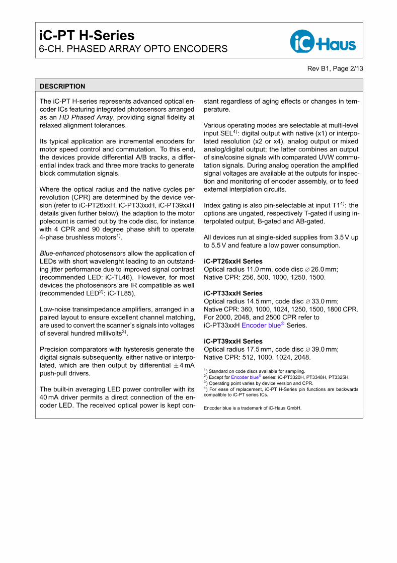
BLOCK DIAGRAM
iC-PT...H
+-
COMMUTATION
COMPARATION
POWER-ONRESET
QUADRATURE
D1
OUTPUT
OUTPUT
CONTROL
SIGNAL
INDEX
POWER
AND
NA
NB
NZ
PB
PZ
PA
LED
W
U
V
R147
1uFC1
VCC
PA
SEL
+3.5..5.5V
TIP
NB
U
PB
PZ
T1
V
GND
TIN
NA
W
LED
NZ
Copyright © 2014, 2016 iC-Haus http://www.ichaus.com
iC-PT H-Series6-CH. PHASED ARRAY OPTO ENCODERS
Rev B1, Page 2/13
DESCRIPTION
The iC-PT H-series represents advanced optical en-coder ICs featuring integrated photosensors arrangedas an HD Phased Array, providing signal fidelity atrelaxed alignment tolerances.
Its typical application are incremental encoders formotor speed control and commutation. To this end,the devices provide differential A/B tracks, a differ-ential index track and three more tracks to generateblock commutation signals.
Where the optical radius and the native cycles perrevolution (CPR) are determined by the device ver-sion (refer to iC-PT26xxH, iC-PT33xxH, iC-PT39xxHdetails given further below), the adaption to the motorpolecount is carried out by the code disc, for instancewith 4 CPR and 90 degree phase shift to operate4-phase brushless motors1).
Blue-enhanced photosensors allow the application ofLEDs with short wavelenght leading to an outstand-ing jitter performance due to improved signal contrast(recommended LED: iC-TL46). However, for mostdevices the photosensors are IR compatible as well(recommended LED2): iC-TL85).
Low-noise transimpedance amplifiers, arranged in apaired layout to ensure excellent channel matching,are used to convert the scanner’s signals into voltagesof several hundred millivolts3).
Precision comparators with hysteresis generate thedigital signals subsequently, either native or interpo-lated, which are then output by differential ±4 mApush-pull drivers.
The built-in averaging LED power controller with its40 mA driver permits a direct connection of the en-coder LED. The received optical power is kept con-
stant regardless of aging effects or changes in tem-perature.
Various operating modes are selectable at multi-levelinput SEL4): digital output with native (x1) or interpo-lated resolution (x2 or x4), analog output or mixedanalog/digital output; the latter combines an outputof sine/cosine signals with comparated UVW commu-tation signals. During analog operation the amplifiedsignal voltages are available at the outputs for inspec-tion and monitoring of encoder assembly, or to feedexternal interplation circuits.
Index gating is also pin-selectable at input T14): theoptions are ungated, respectively T-gated if using in-terpolated output, B-gated and AB-gated.
All devices run at single-sided supplies from 3.5 V upto 5.5 V and feature a low power consumption.
iC-PT26xxH SeriesOptical radius 11.0 mm, code disc ∅26.0 mm;Native CPR: 256, 500, 1000, 1250, 1500.
iC-PT33xxH SeriesOptical radius 14.5 mm, code disc ∅33.0 mm;Native CPR: 360, 1000, 1024, 1250, 1500, 1800 CPR.For 2000, 2048, and 2500 CPR refer toiC-PT33xxH Encoder blue® Series.
iC-PT39xxH SeriesOptical radius 17.5 mm, code disc ∅39.0 mm;Native CPR: 512, 1000, 1024, 2048.1) Standard on code discs available for sampling.2) Except for Encoder blue® series: iC-PT3320H, PT3348H, PT3325H.3) Operating point varies by device version and CPR.4) For ease of replacement, iC-PT H-Series pin functions are backwardscompatible to iC-PT series ICs.
Encoder blue is a trademark of iC-Haus GmbH.
iC-PT H-Series6-CH. PHASED ARRAY OPTO ENCODERS
Rev B1, Page 3/13
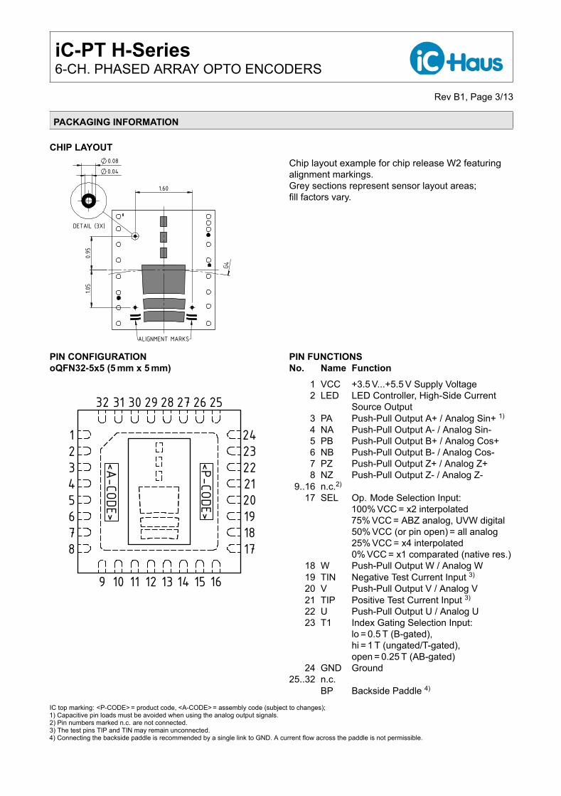
PACKAGING INFORMATION
CHIP LAYOUT
1.60
0.95
1.05
G4
ALIGNMENT MARKS
0.04 0.08
DETAIL (3X)
dra_ptxxxxh_w2_chip_1, 20:1
Chip layout example for chip release W2 featuringalignment markings.Grey sections represent sensor layout areas;fill factors vary.
PIN CONFIGURATIONoQFN32-5x5 (5 mm x 5 mm)
12345678
9 10 11 12 13 14 15 16
1718192021222324
2526272829303132
<A-CODE>
<P-CODE>PIN FUNCTIONSNo. Name Function
1 VCC +3.5 V...+5.5 V Supply Voltage2 LED LED Controller, High-Side Current
Source Output3 PA Push-Pull Output A+ / Analog Sin+ 1)
4 NA Push-Pull Output A- / Analog Sin-5 PB Push-Pull Output B+ / Analog Cos+6 NB Push-Pull Output B- / Analog Cos-7 PZ Push-Pull Output Z+ / Analog Z+8 NZ Push-Pull Output Z- / Analog Z-
9..16 n.c.2)
17 SEL Op. Mode Selection Input:100% VCC = x2 interpolated75% VCC = ABZ analog, UVW digital50% VCC (or pin open) = all analog25% VCC = x4 interpolated0% VCC = x1 comparated (native res.)
18 W Push-Pull Output W / Analog W19 TIN Negative Test Current Input 3)
20 V Push-Pull Output V / Analog V21 TIP Positive Test Current Input 3)
22 U Push-Pull Output U / Analog U23 T1 Index Gating Selection Input:
lo = 0.5 T (B-gated),hi = 1 T (ungated/T-gated),open = 0.25 T (AB-gated)
24 GND Ground25..32 n.c.
BP Backside Paddle 4)
IC top marking: <P-CODE> = product code, <A-CODE> = assembly code (subject to changes);1) Capacitive pin loads must be avoided when using the analog output signals.2) Pin numbers marked n.c. are not connected.3) The test pins TIP and TIN may remain unconnected.4) Connecting the backside paddle is recommended by a single link to GND. A current flow across the paddle is not permissible.
iC-PT H-Series6-CH. PHASED ARRAY OPTO ENCODERS
Rev B1, Page 4/13
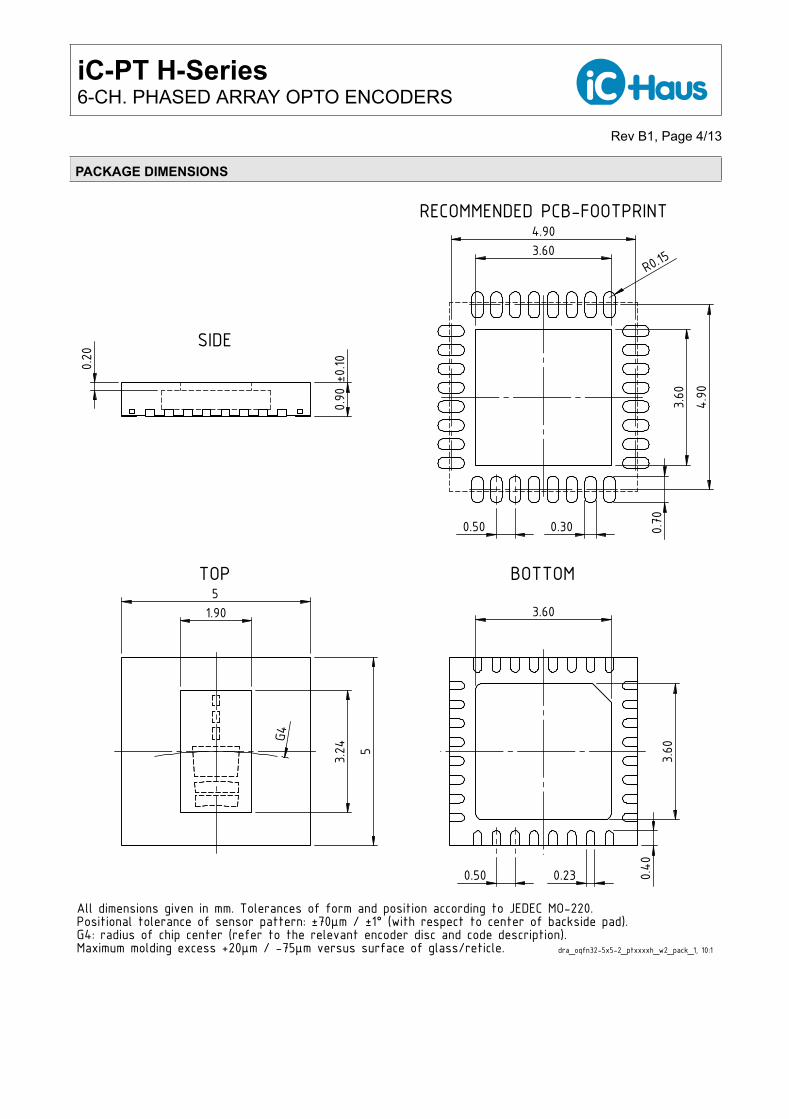
PACKAGE DIMENSIONS
5
5
1.90
3.24 G
4
TOP
All dimensions given in mm. Tolerances of form and position according to JEDEC MO-220.Positional tolerance of sensor pattern: ±70μm / ±1° (with respect to center of backside pad).G4: radius of chip center (refer to the relevant encoder disc and code description).Maximum molding excess +20μm / -75μm versus surface of glass/reticle.
0.90
±0.10 0.20 SIDE
3.60
3.60
0.50 0.23 0.40
BOTTOM
3.60
3.60
0.50 0.30
4.90
4.90
R0.15
0.70
RECOMMENDED PCB-FOOTPRINT
dra_oqfn32-5x5-2_ptxxxxh_w2_pack_1, 10:1
iC-PT H-Series6-CH. PHASED ARRAY OPTO ENCODERS
Rev B1, Page 5/13
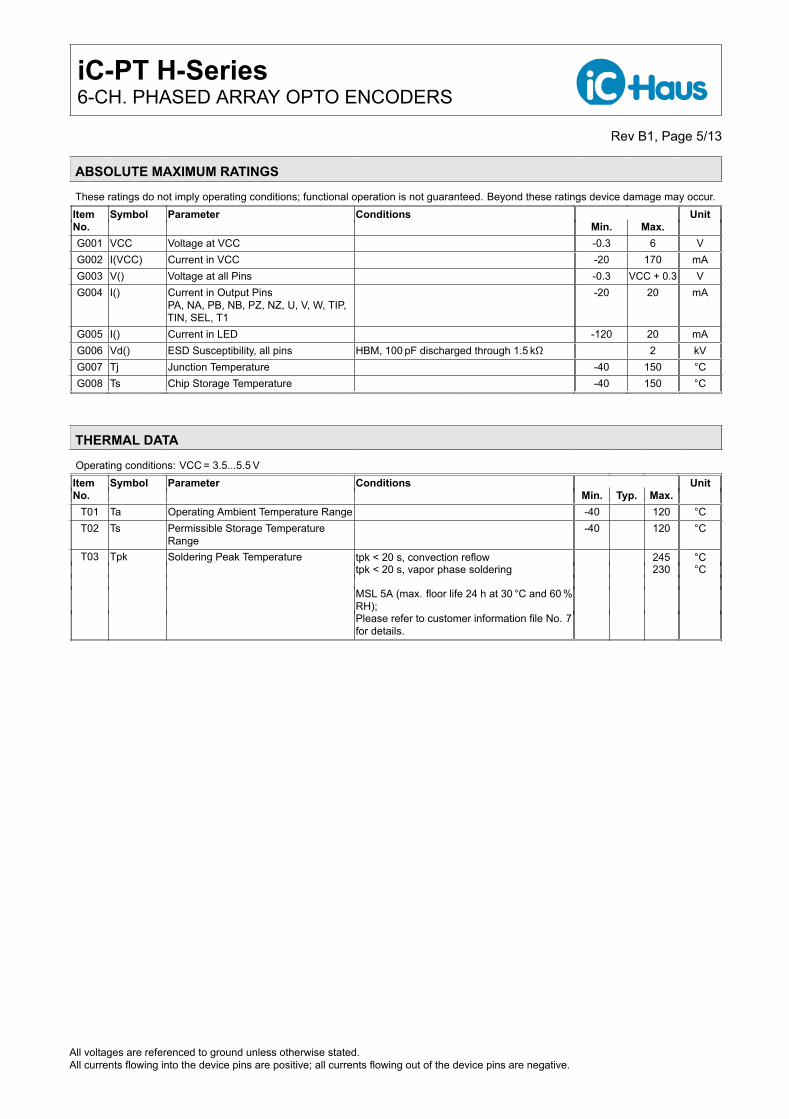
ABSOLUTE MAXIMUM RATINGS
These ratings do not imply operating conditions; functional operation is not guaranteed. Beyond these ratings device damage may occur.Item Symbol Parameter Conditions UnitNo. Min. Max.G001 VCC Voltage at VCC -0.3 6 VG002 I(VCC) Current in VCC -20 170 mAG003 V() Voltage at all Pins -0.3 VCC + 0.3 VG004 I() Current in Output Pins
PA, NA, PB, NB, PZ, NZ, U, V, W, TIP,TIN, SEL, T1
-20 20 mA
G005 I() Current in LED -120 20 mAG006 Vd() ESD Susceptibility, all pins HBM, 100 pF discharged through 1.5 kΩ 2 kVG007 Tj Junction Temperature -40 150 °CG008 Ts Chip Storage Temperature -40 150 °C
THERMAL DATA
Operating conditions: VCC = 3.5...5.5 VItem Symbol Parameter Conditions UnitNo. Min. Typ. Max.
T01 Ta Operating Ambient Temperature Range -40 120 °CT02 Ts Permissible Storage Temperature
Range-40 120 °C
T03 Tpk Soldering Peak Temperature tpk < 20 s, convection reflow 245 °Ctpk < 20 s, vapor phase soldering 230 °C
MSL 5A (max. floor life 24 h at 30 °C and 60 %RH);Please refer to customer information file No. 7for details.
All voltages are referenced to ground unless otherwise stated.All currents flowing into the device pins are positive; all currents flowing out of the device pins are negative.
iC-PT H-Series6-CH. PHASED ARRAY OPTO ENCODERS
Rev B1, Page 6/13
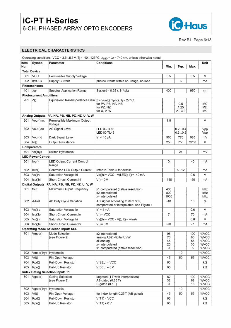
ELECTRICAL CHARACTERISTICS
Operating conditions: VCC = 3.5...5.5 V, Tj = -40...125 °C, λLED = λr = 740 nm, unless otherwise notedItem Symbol Parameter Conditions UnitNo. Min. Typ. Max.Total Device001 VCC Permissible Supply Voltage 3.5 5.5 V002 I(VCC) Supply Current photocurrents within op. range, no load 6 mA
Photosensors101 λar Spectral Application Range Se(λar) = 0.25 x S(λpk) 400 950 nm
Photocurrent Amplifiers201 Z() Equivalent Transimpedance Gain Z = Vout() / Iph(), Tj = 27 °C;
for PA, PB, NA, NB 0.5 MΩfor PZ, NZ 1.25 MΩfor U, V, W 2... 3.2 MΩ
Analog Outputs: PA, NA, PB, NB, PZ, NZ, U, V, W301 Vout()mx Permissible Maximum Output
Voltage1.8 V
302 Vout()ac AC Signal Level LED iC-TL85 0.2...0.4 VppLED iC-TL46 0.3...0.5 Vpp
303 Vout()d Dark Signal Level I() < 10µA 560 770 985 mV304 Ri() Output Resistance 250 750 2250 Ω
Comparators401 Vt()hys Switch Hysteresis 24 mV
LED Power Control501 Iop() LED Output Current Control
Range0 40 mA
502 Ictrl() Controlled LED Output Current refer to Table 5 for details 5...12 mA503 Vs()hi Saturation Voltage hi Vs()hi = VCC - V(LED); I() = -40 mA 0.6 V504 Isc()hi Short-Circuit Current hi V() = 0 V -150 -50 mA
Digital Outputs: PA, NA, PB, NB, PZ, NZ, U, V, W601 fout Maximum Output Frequency x1 comparated (native resolution) 400 kHz
x2 interpolated 800 kHzx4 interpolated 1600 kHz
602 AArel AB Duty Cycle Variation AC signal according to item 302,comparated or interpolated, see Figure 1
-10 10 %
603 Vs()lo Saturation Voltage lo I() = 4 mA 0.6 V604 Isc()lo Short-Circuit Current lo V() = VCC 7 70 mA605 Vs()hi Saturation Voltage hi Vs()hi = VCC - V(), I() = -4 mA 0.6 V606 Isc()hi Short-Circuit Current hi V() = 0 V -70 -7 mA
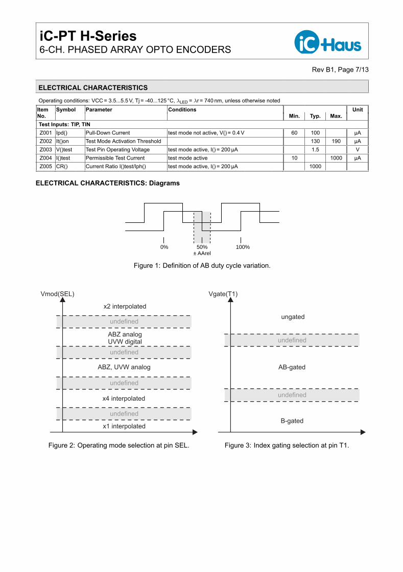
Operating Mode Selection Input: SEL701 Vmod() Mode Selection
(see Figure 2)x2 interpolated 95 100 %VCCanalog ABZ, digital UVW 70 80 %VCCall analog 45 55 %VCCx4 interpolated 20 30 %VCCx1 comparated (native resolution) 0 5 %VCC
702 Vmod()hys Hysteresis 10 %VCC703 V0() Pin-Open Voltage 45 50 55 %VCC704 Rpd() Pull-Down Resistor V(SEL) = VCC 65 kΩ705 Rpu() Pull-Up Resistor V(SEL) = 0 V 65 kΩ
Index Gating Selection Input: T1801 Vgate() Gating Selection
(see Figure 3)ungated (1 T with interpolation) 82 100 %VCCAB-gated (0.25 T) 32 68 %VCCB-gated (0.5 T) 0 18 %VCC
802 Vgate()hys Hysteresis 10 %VCC803 V0() Pin-Open Voltage for index length 0.25 T (AB-gated) 45 50 55 %VCC804 Rpd() Pull-Down Resistor V(T1) = VCC 65 kΩ805 Rpu() Pull-Up Resistor V(T1) = 0 V 65 kΩ
iC-PT H-Series6-CH. PHASED ARRAY OPTO ENCODERS
Rev B1, Page 7/13
ELECTRICAL CHARACTERISTICS
Operating conditions: VCC = 3.5...5.5 V, Tj = -40...125 °C, λLED = λr = 740 nm, unless otherwise notedItem Symbol Parameter Conditions UnitNo. Min. Typ. Max.Test Inputs: TIP, TINZ001 Ipd() Pull-Down Current test mode not active, V() = 0.4 V 60 100 µAZ002 It()on Test Mode Activation Threshold 130 190 µAZ003 V()test Test Pin Operating Voltage test mode active, I() = 200µA 1.5 VZ004 I()test Permissible Test Current test mode active 10 1000 µAZ005 CR() Current Ratio I()test/Iph() test mode active, I() = 200µA 1000
ELECTRICAL CHARACTERISTICS: Diagrams
0% 100% 50% ± AArel
Figure 1: Definition of AB duty cycle variation.
undefined
undefined
undefined
undefined
x1 interpolated
x4 interpolated
ABZ, UVW analog
ABZ analogUVW digital
x2 interpolated
Vmod(SEL)
Figure 2: Operating mode selection at pin SEL.
undefined
undefined
B-gated
AB-gated
ungated
Vgate(T1)
Figure 3: Index gating selection at pin T1.
iC-PT H-Series6-CH. PHASED ARRAY OPTO ENCODERS
Rev B1, Page 8/13
DIGITAL OUTPUT SIGNALS
T
T/4 T/4 T/4 T/4
PA
PB
PZ
U
V
W
C/6 C/6 C/6 C/6 C/6 C/6
C
ö
PZPZ
AB-gated
B-gated ungated
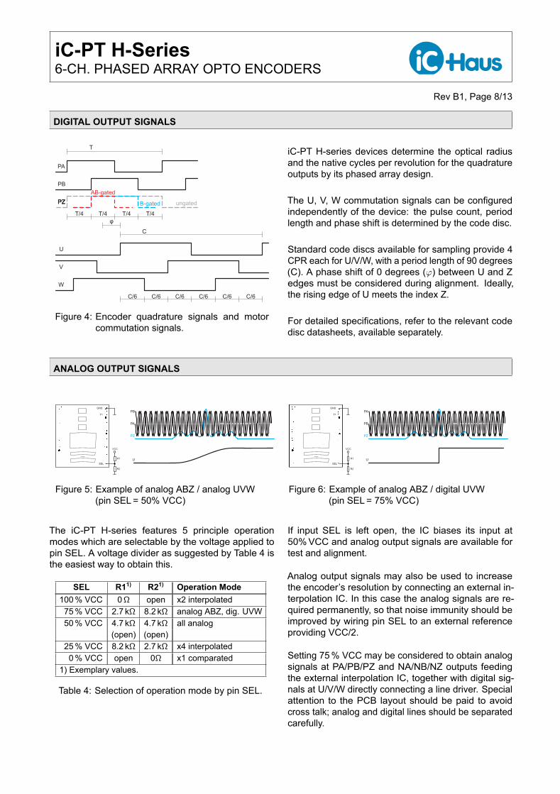
Figure 4: Encoder quadrature signals and motorcommutation signals.
iC-PT H-series devices determine the optical radiusand the native cycles per revolution for the quadratureoutputs by its phased array design.
The U, V, W commutation signals can be configuredindependently of the device: the pulse count, periodlength and phase shift is determined by the code disc.
Standard code discs available for sampling provide 4CPR each for U/V/W, with a period length of 90 degrees(C). A phase shift of 0 degrees (φ) between U and Zedges must be considered during alignment. Ideally,the rising edge of U meets the index Z.
For detailed specifications, refer to the relevant codedisc datasheets, available separately.
ANALOG OUTPUT SIGNALS
GND
T1
SEL
iC-PTxxxx
VCC
U
PB
PA
PZ
R1
R2
Figure 5: Example of analog ABZ / analog UVW(pin SEL = 50% VCC)
GND
T1
SEL
iC-PTxxxx
VCC
U
PA
PB
PZ
R1
R2
Figure 6: Example of analog ABZ / digital UVW(pin SEL = 75% VCC)
The iC-PT H-series features 5 principle operationmodes which are selectable by the voltage applied topin SEL. A voltage divider as suggested by Table 4 isthe easiest way to obtain this.
SEL R11) R21) Operation Mode100 % VCC 0Ω open x2 interpolated
75 % VCC 2.7 kΩ 8.2 kΩ analog ABZ, dig. UVW50 % VCC 4.7 kΩ 4.7 kΩ all analog
(open) (open)25 % VCC 8.2 kΩ 2.7 kΩ x4 interpolated
0 % VCC open 0Ω x1 comparated1) Exemplary values.
Table 4: Selection of operation mode by pin SEL.
If input SEL is left open, the IC biases its input at50% VCC and analog output signals are available fortest and alignment.
Analog output signals may also be used to increasethe encoder’s resolution by connecting an external in-terpolation IC. In this case the analog signals are re-quired permanently, so that noise immunity should beimproved by wiring pin SEL to an external referenceproviding VCC/2.
Setting 75 % VCC may be considered to obtain analogsignals at PA/PB/PZ and NA/NB/NZ outputs feedingthe external interpolation IC, together with digital sig-nals at U/V/W directly connecting a line driver. Specialattention to the PCB layout should be paid to avoidcross talk; analog and digital lines should be separatedcarefully.
iC-PT H-Series6-CH. PHASED ARRAY OPTO ENCODERS
Rev B1, Page 9/13
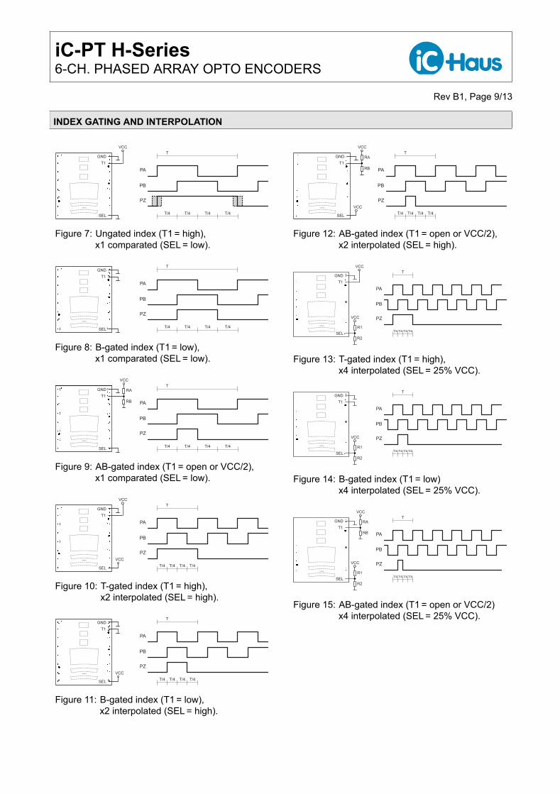
INDEX GATING AND INTERPOLATION
PA
PB
PZ
GND
iC-PTxxxx
VCC
T
T/4 T/4 T/4 T/4
T1
SEL
Figure 7: Ungated index (T1 = high),x1 comparated (SEL = low).
iC-PTxxxx
T
T/4 T/4 T/4 T/4
PA
PB
PZ
GND
T1
SEL
Figure 8: B-gated index (T1 = low),x1 comparated (SEL = low).
iC-PTxxxx
T
T/4 T/4 T/4 T/4
PA
PB
PZ
VCC
RA
RB
GND
T1
SEL
Figure 9: AB-gated index (T1 = open or VCC/2),x1 comparated (SEL = low).
iC-PTxxxx VCC
T
T/4 T/4 T/4 T/4
PA
PB
PZ
GND
T1
SEL
VCC
Figure 10: T-gated index (T1 = high),x2 interpolated (SEL = high).
iC-PTxxxx VCC
T
T/4 T/4 T/4 T/4
PA
PB
PZ
GND
T1
SEL
Figure 11: B-gated index (T1 = low),x2 interpolated (SEL = high).
iC-PTxxxx VCC
T
T/4 T/4 T/4 T/4
PA
PB
PZ
VCC
RA
RB
GND
T1
SEL
Figure 12: AB-gated index (T1 = open or VCC/2),x2 interpolated (SEL = high).
iC-PTxxxx
VCC
R1
R2
T
T/4 T/4 T/4 T/4
PA
PB
PZ
GND
T1
SEL
VCC
Figure 13: T-gated index (T1 = high),x4 interpolated (SEL = 25% VCC).
iC-PTxxxx
VCC
R1
R2
T
T/4 T/4 T/4 T/4
PA
PB
PZ
GND
T1
SEL
Figure 14: B-gated index (T1 = low)x4 interpolated (SEL = 25% VCC).
iC-PTxxxx
VCC
R1
R2
T
T/4 T/4 T/4 T/4
PA
PB
PZ
VCC
RA
RB
GND
T1
SEL
Figure 15: AB-gated index (T1 = open or VCC/2)x4 interpolated (SEL = 25% VCC).
iC-PT H-Series6-CH. PHASED ARRAY OPTO ENCODERS
Rev B1, Page 10/13
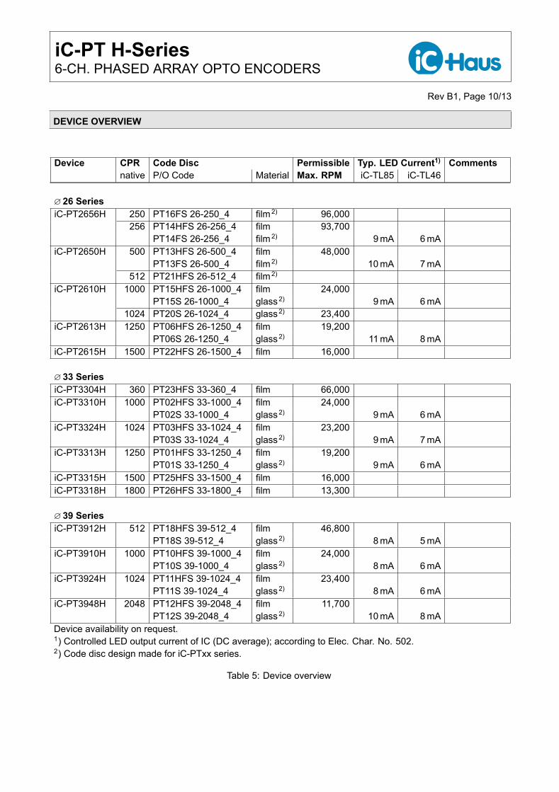
DEVICE OVERVIEW
Device CPR Code Disc Permissible Typ. LED Current1) Commentsnative P/O Code Material Max. RPM iC-TL85 iC-TL46
∅26 SeriesiC-PT2656H 250 PT16FS 26-250_4 film2) 96,000
256 PT14HFS 26-256_4 film 93,700PT14FS 26-256_4 film2) 9 mA 6 mA
iC-PT2650H 500 PT13HFS 26-500_4 film 48,000PT13FS 26-500_4 film2) 10 mA 7 mA
512 PT21HFS 26-512_4 film2)
iC-PT2610H 1000 PT15HFS 26-1000_4 film 24,000PT15S 26-1000_4 glass2) 9 mA 6 mA
1024 PT20S 26-1024_4 glass2) 23,400iC-PT2613H 1250 PT06HFS 26-1250_4 film 19,200
PT06S 26-1250_4 glass2) 11 mA 8 mAiC-PT2615H 1500 PT22HFS 26-1500_4 film 16,000
∅33 SeriesiC-PT3304H 360 PT23HFS 33-360_4 film 66,000iC-PT3310H 1000 PT02HFS 33-1000_4 film 24,000
PT02S 33-1000_4 glass2) 9 mA 6 mAiC-PT3324H 1024 PT03HFS 33-1024_4 film 23,200
PT03S 33-1024_4 glass2) 9 mA 7 mAiC-PT3313H 1250 PT01HFS 33-1250_4 film 19,200
PT01S 33-1250_4 glass2) 9 mA 6 mAiC-PT3315H 1500 PT25HFS 33-1500_4 film 16,000iC-PT3318H 1800 PT26HFS 33-1800_4 film 13,300
∅39 SeriesiC-PT3912H 512 PT18HFS 39-512_4 film 46,800
PT18S 39-512_4 glass2) 8 mA 5 mAiC-PT3910H 1000 PT10HFS 39-1000_4 film 24,000
PT10S 39-1000_4 glass2) 8 mA 6 mAiC-PT3924H 1024 PT11HFS 39-1024_4 film 23,400
PT11S 39-1024_4 glass2) 8 mA 6 mAiC-PT3948H 2048 PT12HFS 39-2048_4 film 11,700
PT12S 39-2048_4 glass2) 10 mA 8 mADevice availability on request.1) Controlled LED output current of IC (DC average); according to Elec. Char. No. 502.2) Code disc design made for iC-PTxx series.
Table 5: Device overview
iC-PT H-Series6-CH. PHASED ARRAY OPTO ENCODERS
Rev B1, Page 11/13
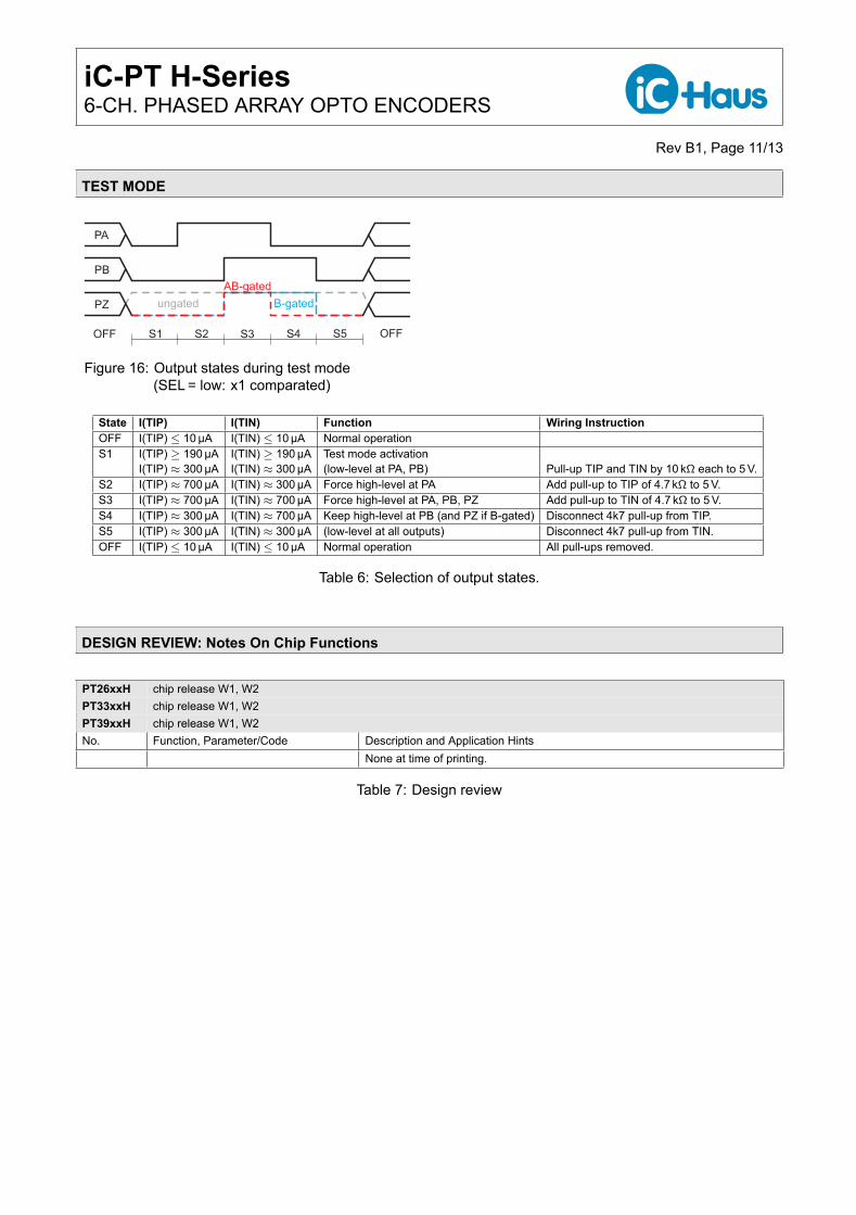
TEST MODE
S2 S3 S4 S5
PA
PB
PZ
AB-gated
B-gated
S1OFF OFF
ungated
Figure 16: Output states during test mode(SEL = low: x1 comparated)
State I(TIP) I(TIN) Function Wiring InstructionOFF I(TIP) ≤ 10µA I(TIN) ≤ 10µA Normal operationS1 I(TIP) ≥ 190µA I(TIN) ≥ 190µA Test mode activation
I(TIP) ≈ 300µA I(TIN) ≈ 300µA (low-level at PA, PB) Pull-up TIP and TIN by 10 kΩ each to 5 V.S2 I(TIP) ≈ 700µA I(TIN) ≈ 300µA Force high-level at PA Add pull-up to TIP of 4.7 kΩ to 5 V.S3 I(TIP) ≈ 700µA I(TIN) ≈ 700µA Force high-level at PA, PB, PZ Add pull-up to TIN of 4.7 kΩ to 5 V.S4 I(TIP) ≈ 300µA I(TIN) ≈ 700µA Keep high-level at PB (and PZ if B-gated) Disconnect 4k7 pull-up from TIP.S5 I(TIP) ≈ 300µA I(TIN) ≈ 300µA (low-level at all outputs) Disconnect 4k7 pull-up from TIN.OFF I(TIP) ≤ 10µA I(TIN) ≤ 10µA Normal operation All pull-ups removed.
Table 6: Selection of output states.
DESIGN REVIEW: Notes On Chip Functions
PT26xxH chip release W1, W2PT33xxH chip release W1, W2PT39xxH chip release W1, W2No. Function, Parameter/Code Description and Application Hints
None at time of printing.
Table 7: Design review
iC-PT H-Series6-CH. PHASED ARRAY OPTO ENCODERS
Rev B1, Page 12/13
APPLICATION NOTES
Application notes for iC-PT H-series devices are available separately.
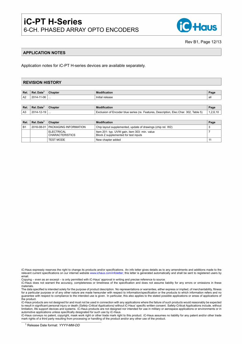
REVISION HISTORY
Rel. Rel. Date1 Chapter Modification PageA2 2014-11-06 ... Initial release all
Rel. Rel. Date1 Chapter Modification PageA3 2014-12-19 ... Exclusion of Encoder blue series (re. Features, Description, Elec.Char. 302, Table 5) 1,2,6,10
Rel. Rel. Date1 Chapter Modification PageB1 2016-08-01 PACKAGING INFORMATION Chip layout supplemented, update of drawings (chip rel. W2) 3
ELECTRICALCHARACTERISTICS
Item 201: typ. UVW gain, item 303: min. valueBlock Z supplemented for test inputs
7
TEST MODE New chapter added 11
iC-Haus expressly reserves the right to change its products and/or specifications. An info letter gives details as to any amendments and additions made to therelevant current specifications on our internet website www.ichaus.com/infoletter; this letter is generated automatically and shall be sent to registered users byemail.Copying – even as an excerpt – is only permitted with iC-Haus’ approval in writing and precise reference to source.iC-Haus does not warrant the accuracy, completeness or timeliness of the specification and does not assume liability for any errors or omissions in thesematerials.The data specified is intended solely for the purpose of product description. No representations or warranties, either express or implied, of merchantability, fitnessfor a particular purpose or of any other nature are made hereunder with respect to information/specification or the products to which information refers and noguarantee with respect to compliance to the intended use is given. In particular, this also applies to the stated possible applications or areas of applications ofthe product.iC-Haus products are not designed for and must not be used in connection with any applications where the failure of such products would reasonably be expectedto result in significant personal injury or death (Safety-Critical Applications) without iC-Haus’ specific written consent. Safety-Critical Applications include, withoutlimitation, life support devices and systems. iC-Haus products are not designed nor intended for use in military or aerospace applications or environments or inautomotive applications unless specifically designated for such use by iC-Haus.iC-Haus conveys no patent, copyright, mask work right or other trade mark right to this product. iC-Haus assumes no liability for any patent and/or other trademark rights of a third party resulting from processing or handling of the product and/or any other use of the product.
1 Release Date format: YYYY-MM-DD
iC-PT H-Series6-CH. PHASED ARRAY OPTO ENCODERS
Rev B1, Page 13/13
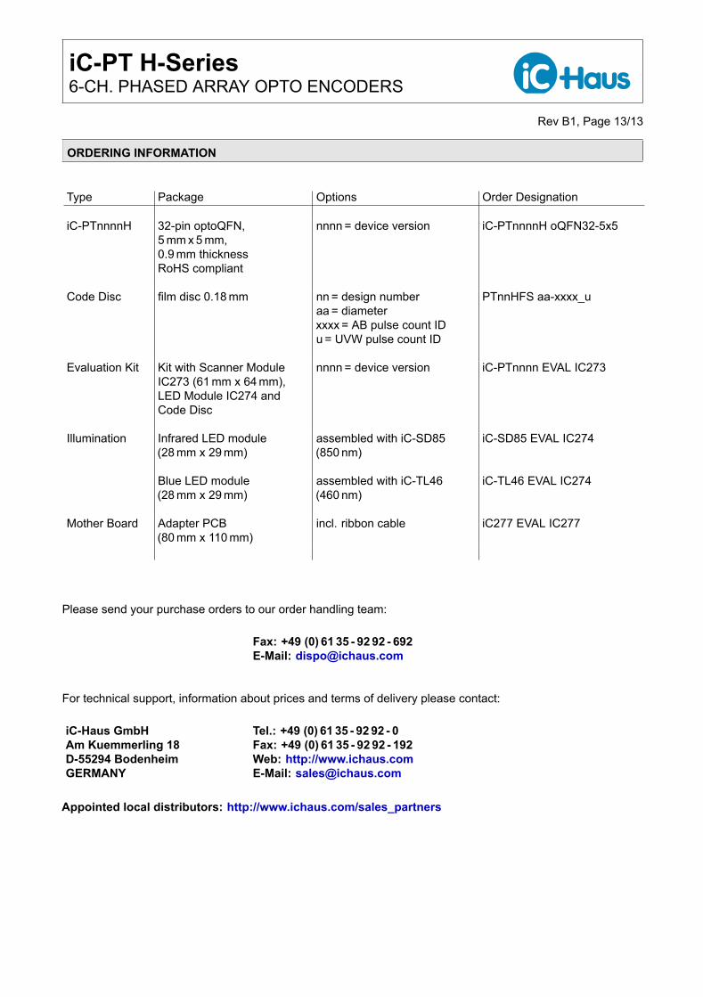
ORDERING INFORMATION
Type Package Options Order Designation
iC-PTnnnnH 32-pin optoQFN,5 mm x 5 mm,0.9 mm thicknessRoHS compliant
nnnn = device version iC-PTnnnnH oQFN32-5x5
Code Disc film disc 0.18 mm nn = design numberaa = diameterxxxx = AB pulse count IDu = UVW pulse count ID
PTnnHFS aa-xxxx_u
Evaluation Kit Kit with Scanner ModuleIC273 (61 mm x 64 mm),LED Module IC274 andCode Disc
nnnn = device version iC-PTnnnn EVAL IC273
Illumination Infrared LED module(28 mm x 29 mm)
assembled with iC-SD85(850 nm)
iC-SD85 EVAL IC274
Blue LED module(28 mm x 29 mm)
assembled with iC-TL46(460 nm)
iC-TL46 EVAL IC274
Mother Board Adapter PCB(80 mm x 110 mm)
incl. ribbon cable iC277 EVAL IC277
Please send your purchase orders to our order handling team:
Fax: +49 (0) 61 35 - 92 92 - 692E-Mail: [email protected]
For technical support, information about prices and terms of delivery please contact:
iC-Haus GmbH Tel.: +49 (0) 61 35 - 92 92 - 0Am Kuemmerling 18 Fax: +49 (0) 61 35 - 92 92 - 192D-55294 Bodenheim Web: http://www.ichaus.comGERMANY E-Mail: [email protected]
Appointed local distributors: http://www.ichaus.com/sales_partners