Embed Size (px)
Citation preview
ICON Pro Series GaugeUser’s Guide
*766075*
ICO
N Pro Series G
auge User’s G
uide P
/N 766075 R
ev A.
Rev A.

IMPORTANT: This User’s Guide outlines the functionality and usage of ICON gauges. Before using theICON gauges, first read and understand all of the supplied product literature, as well as the boat’s user’sguide and outboard’s operator’s guide. This user’s guide should be stored onboard for reference.
The photographs, illustrations, and display screens used in this guide might not depict actual models, fig-ures, data fields, equipment, or software versions, but are intended as representative views for referenceonly. The continuing accuracy of this guide cannot be guaranteed.
† NMEA 2000 is a registered trademark of the National Marine Electronics Association or its subsidiaries.
The following trademarks are the property of Bombardier Recreational Products Inc. or its affiliates.
BRP US Inc. / Outboard Engines Division After Sales Support P.O. Box 597 Sturtevant, WI 53177
Evinrude ® E-TEC ®
Evinrude ®
Johnson ®
ICON ™ Electronic Remote Control System
ICON ™ Gauge Package
S.A.F.E. ™ (Speed Adjusting Failsafe Electronics)
Printed in the United States.© 2016 BRP US Inc. All rights reserved.TM, ® Trademarks and registered trademarks of Bombardier Recreational Products Inc. or its affiliates.
About This GuideIMPORTANT: Read this user’s guide carefullybefore using the ICON gauges. This user’s guideshould be kept onboard at all times during opera-tion.
For any questions regarding the boat or outboardoperation, please refer to the boat’s user’s guide, oroutboard’s operator’s guide for support information.
For questions or problems regarding the ICONgauge, contact your dealer.
Dealers with questions should contact BRP Partsand Accessories Technical Help.
� WARNINGFor your safety and the safety of others, fol-low all safety warnings and recommendationssupplied with the boat and outboard. Do notdisregard any of the safety precautions andinstructions
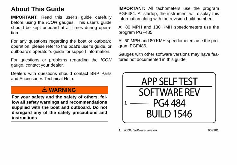
IMPORTANT: All tachometers use the programPGF484. At startup, the instrument will display thisinformation along with the revision build number.
All 80 MPH and 130 KMH speedometers use theprogram PGF485.
All 50 MPH and 80 KMH speedometers use the pro-gram PGF486.
Gauges with other software versions may have fea-tures not documented in this guide.
1. ICON Software version 009961
1
Table of ContentsAbout This Guide . . . . . . . . . . . . . . . . . . . . . . . . . .2Table of Contents . . . . . . . . . . . . . . . . . . . . . . . . . .3Select Language . . . . . . . . . . . . . . . . . . . . . . . . . . .8Select Clock Offset/GMT . . . . . . . . . . . . . . . . . . . .9Engine Initialization . . . . . . . . . . . . . . . . . . . . . . .10Engine Type . . . . . . . . . . . . . . . . . . . . . . . . . . . . .11Default Display Units . . . . . . . . . . . . . . . . . . . . . .12Tank Setup (G1 Engines) . . . . . . . . . . . . . . . . . . .13Tank Setup (G2 Engines) . . . . . . . . . . . . . . . . . . .14Fuel Totalizer . . . . . . . . . . . . . . . . . . . . . . . . . . . .19Reset the Totalizer Fuel Used . . . . . . . . . . . . . . . .19Contrast Settings . . . . . . . . . . . . . . . . . . . . . . . . . .21Backlight Settings . . . . . . . . . . . . . . . . . . . . . . . . .22Fuel Level . . . . . . . . . . . . . . . . . . . . . . . . . . . . . . .23Setting the Fuel Level . . . . . . . . . . . . . . . . . . . . . .24Adding Fuel to the Fuel Tank . . . . . . . . . . . . . . . .26Trip Data . . . . . . . . . . . . . . . . . . . . . . . . . . . . . . . .27View Trip and Season Data . . . . . . . . . . . . . . . . .28Resetting Trip and Season Data . . . . . . . . . . . . . .29Gear Position Indicator . . . . . . . . . . . . . . . . . . . . .33Alarms . . . . . . . . . . . . . . . . . . . . . . . . . . . . . . . . . .34Custom Alarms . . . . . . . . . . . . . . . . . . . . . . . . . . .34Evinrude Alarms . . . . . . . . . . . . . . . . . . . . . . . . . .34
SYSTEM . . . . . . . . . . . . . . . . . . . . . . . . . . . . . . . .36Initialization . . . . . . . . . . . . . . . . . . . . . . . . . . . . .37System Language . . . . . . . . . . . . . . . . . . . . . . . . .38Audio Settings . . . . . . . . . . . . . . . . . . . . . . . . . . .39Clock Settings . . . . . . . . . . . . . . . . . . . . . . . . . . . .43Set Display Units . . . . . . . . . . . . . . . . . . . . . . . . .47Self Test . . . . . . . . . . . . . . . . . . . . . . . . . . . . . . . .48Fuel Added Auto Detect . . . . . . . . . . . . . . . . . . . .49Software Version . . . . . . . . . . . . . . . . . . . . . . . . .50Master Reset . . . . . . . . . . . . . . . . . . . . . . . . . . . . .51Winterizing the Engine (G1 Engines) . . . . . . . . . .52Winterizing the Engine (G2 Engines) . . . . . . . . . .54FUEL SETUP FOR G1 ENGINES . . . . . . . . . . .55Fuel Tank Setup . . . . . . . . . . . . . . . . . . . . . . . . . .56Tank Setup for G2 Engines . . . . . . . . . . . . . . . . . .61Fuel Remaining Source . . . . . . . . . . . . . . . . . . . . .64Max Speed . . . . . . . . . . . . . . . . . . . . . . . . . . . . . .65Available Data Pages . . . . . . . . . . . . . . . . . . . . . .68Display Settings . . . . . . . . . . . . . . . . . . . . . . . . . .69Set Number of Data Pages . . . . . . . . . . . . . . . . . .70Data Page Auto–Scrolling . . . . . . . . . . . . . . . . . .71Screen Setup . . . . . . . . . . . . . . . . . . . . . . . . . . . . .73Setting the Line 2 Data . . . . . . . . . . . . . . . . . . . . .75LCD Color . . . . . . . . . . . . . . . . . . . . . . . . . . . . . .76Data Sources for G1 Engines . . . . . . . . . . . . . . . .77
Tanks . . . . . . . . . . . . . . . . . . . . . . . . . . . . . . . . . . .78Engine . . . . . . . . . . . . . . . . . . . . . . . . . . . . . . . . . .80Trim . . . . . . . . . . . . . . . . . . . . . . . . . . . . . . . . . . .83Battery (G1 Engines) . . . . . . . . . . . . . . . . . . . . . .86Water Temperature . . . . . . . . . . . . . . . . . . . . . . . .87Air Temp . . . . . . . . . . . . . . . . . . . . . . . . . . . . . . . .88Speed . . . . . . . . . . . . . . . . . . . . . . . . . . . . . . . . . . .89Steering Angle . . . . . . . . . . . . . . . . . . . . . . . . . . .90Pop Up Alerts . . . . . . . . . . . . . . . . . . . . . . . . . . . .91To Turn the Pop Up ON or OFF: . . . . . . . . . . . . .92To Set the Pop Up Threshold Value: . . . . . . . . . .93Pop Up Duration . . . . . . . . . . . . . . . . . . . . . . . . . .94Setting Custom Alarms . . . . . . . . . . . . . . . . . . . . .95Data Sources for G2 Engines . . . . . . . . . . . . . . . .98Tanks . . . . . . . . . . . . . . . . . . . . . . . . . . . . . . . . . . .99Remain Source . . . . . . . . . . . . . . . . . . . . . . . . . .100Engine . . . . . . . . . . . . . . . . . . . . . . . . . . . . . . . . .101Trim . . . . . . . . . . . . . . . . . . . . . . . . . . . . . . . . . .102Rudder . . . . . . . . . . . . . . . . . . . . . . . . . . . . . . . . .103Battery (G2 Engines) . . . . . . . . . . . . . . . . . . . . .104Depth Warning (If Equipped) . . . . . . . . . . . . . . .106SYSTEM . . . . . . . . . . . . . . . . . . . . . . . . . . . . . . .110Audio Settings . . . . . . . . . . . . . . . . . . . . . . . . . .111Master Reset . . . . . . . . . . . . . . . . . . . . . . . . . . . .115Software Version . . . . . . . . . . . . . . . . . . . . . . . .116
DISPLAY . . . . . . . . . . . . . . . . . . . . . . . . . . . . . .117Set Number of Data Pages . . . . . . . . . . . . . . . . .118Screen Setup . . . . . . . . . . . . . . . . . . . . . . . . . . . .119Data Page Auto–Scrolling . . . . . . . . . . . . . . . . .121DATA SOURCES . . . . . . . . . . . . . . . . . . . . . . .123Select Speedometer Source . . . . . . . . . . . . . . . . .124Select Sea Water Temperature Source . . . . . . . .125Select Air Temperature Source . . . . . . . . . . . . . .126MAXIMUM SPEED . . . . . . . . . . . . . . . . . . . . . .127

ICON PRO SERIES GaugeSetup
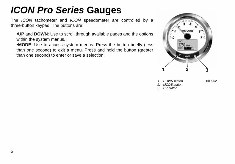
ICON Pro Series GaugesThe ICON tachometer and ICON speedometer are controlled by athree-button keypad. The buttons are:
•UP and DOWN: Use to scroll through available pages and the optionswithin the system menus.•MODE: Use to access system menus. Press the button briefly (lessthan one second) to exit a menu. Press and hold the button (greaterthan one second) to enter or save a selection.
6
1. DOWN button2. MODE button3. UP button
009962
1 32
Power ONThe power ON sequence for the tachometer and speedometer includes aSelf-Test which occurs at every power ON event.
Turn the ignition key to the ON position. Starting the engine is not required.The Self-Test process includes the following steps:
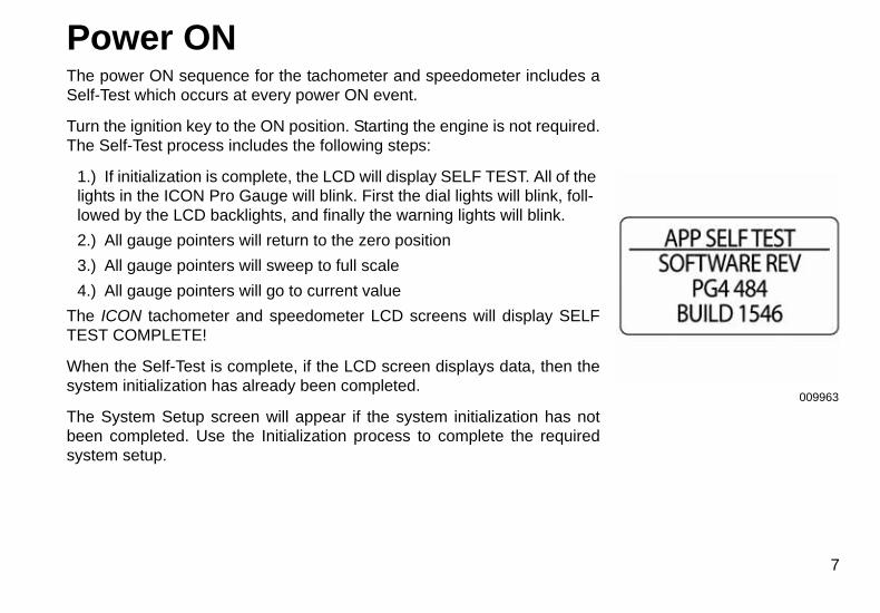
1.) If initialization is complete, the LCD will display SELF TEST. All of the lights in the ICON Pro Gauge will blink. First the dial lights will blink, foll-lowed by the LCD backlights, and finally the warning lights will blink.
2.) All gauge pointers will return to the zero position
3.) All gauge pointers will sweep to full scale
4.) All gauge pointers will go to current value
The ICON tachometer and speedometer LCD screens will display SELFTEST COMPLETE!
When the Self-Test is complete, if the LCD screen displays data, then thesystem initialization has already been completed.
The System Setup screen will appear if the system initialization has notbeen completed. Use the Initialization process to complete the requiredsystem setup.
009963
7
InitializationSystem setup of each tachometer is required for the ICON gauge packageto operate correctly.
To complete the setup process select the default language, set the propersetting on the clock, set the number of engines in the system, select theengine type, select the system default units, configure the different typesof tanks on the vessel and set the tank size. The following sectionsdescribe the steps required to complete the tachometer setup.
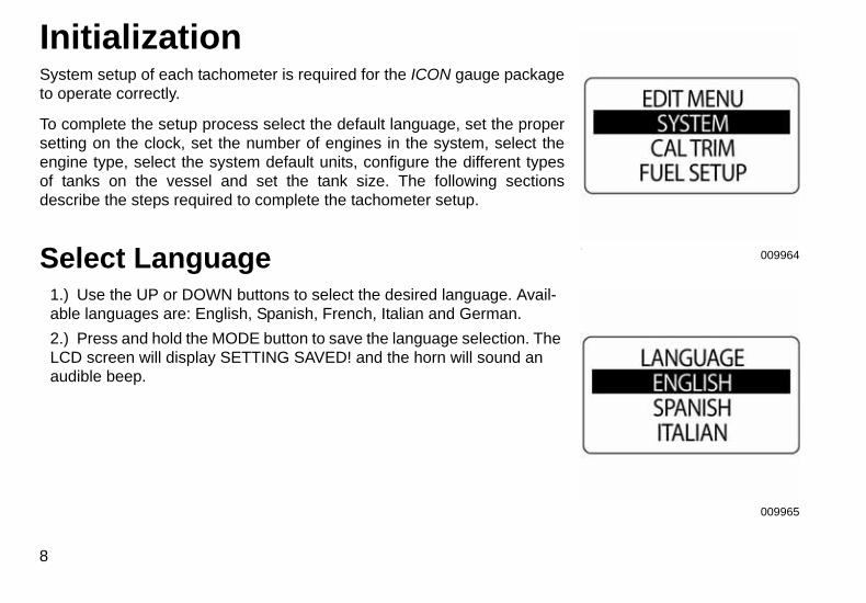
Select Language1.) Use the UP or DOWN buttons to select the desired language. Avail-able languages are: English, Spanish, French, Italian and German.
2.) Press and hold the MODE button to save the language selection. The LCD screen will display SETTING SAVED! and the horn will sound an audible beep.
8
.
009964
009965
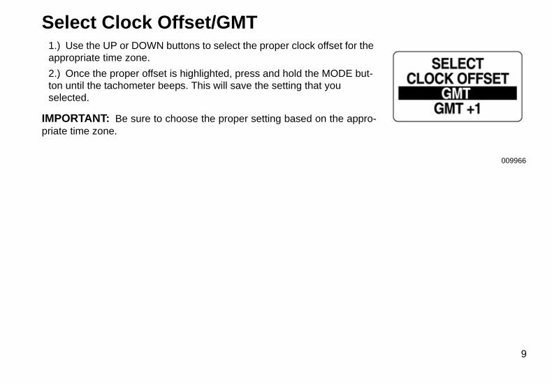
Select Clock Offset/GMT1.) Use the UP or DOWN buttons to select the proper clock offset for the appropriate time zone.
2.) Once the proper offset is highlighted, press and hold the MODE but-ton until the tachometer beeps. This will save the setting that you selected.
IMPORTANT: Be sure to choose the proper setting based on the appro-priate time zone.
009966
9
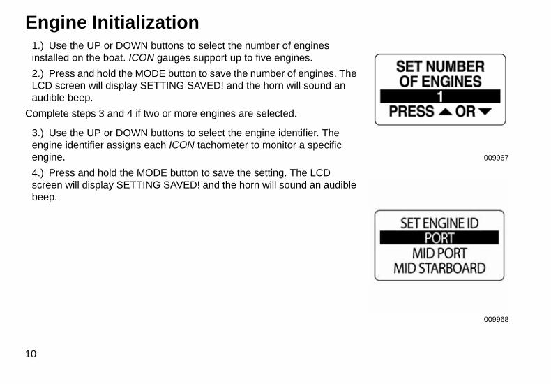
Engine Initialization1.) Use the UP or DOWN buttons to select the number of engines installed on the boat. ICON gauges support up to five engines.
2.) Press and hold the MODE button to save the number of engines. The LCD screen will display SETTING SAVED! and the horn will sound an audible beep.
Complete steps 3 and 4 if two or more engines are selected.
3.) Use the UP or DOWN buttons to select the engine identifier. The engine identifier assigns each ICON tachometer to monitor a specific engine.
4.) Press and hold the MODE button to save the setting. The LCD screen will display SETTING SAVED! and the horn will sound an audible beep.
10
009967
009968
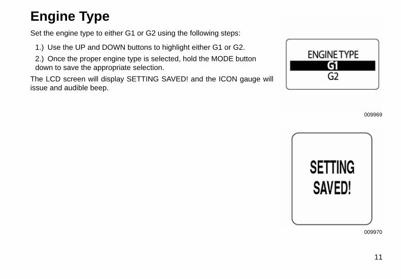
Engine TypeSet the engine type to either G1 or G2 using the following steps:
1.) Use the UP and DOWN buttons to highlight either G1 or G2.
2.) Once the proper engine type is selected, hold the MODE button down to save the appropriate selection.
The LCD screen will display SETTING SAVED! and the ICON gauge willissue and audible beep.
009969
009970
11
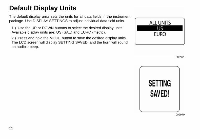
Default Display UnitsThe default display units sets the units for all data fields in the instrumentpackage. Use DISPLAY SETTINGS to adjust individual data field units.
1.) Use the UP or DOWN buttons to select the desired display units. Available display units are: US (SAE) and EURO (metric).
2.) Press and hold the MODE button to save the desired display units. The LCD screen will display SETTING SAVED! and the horn will sound an audible beep.
12
009971
009970
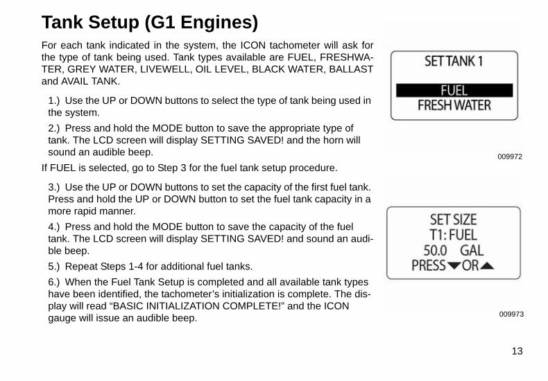
Tank Setup (G1 Engines)For each tank indicated in the system, the ICON tachometer will ask forthe type of tank being used. Tank types available are FUEL, FRESHWA-TER, GREY WATER, LIVEWELL, OIL LEVEL, BLACK WATER, BALLASTand AVAIL TANK.
1.) Use the UP or DOWN buttons to select the type of tank being used in the system.
2.) Press and hold the MODE button to save the appropriate type of tank. The LCD screen will display SETTING SAVED! and the horn will sound an audible beep.
If FUEL is selected, go to Step 3 for the fuel tank setup procedure.
3.) Use the UP or DOWN buttons to set the capacity of the first fuel tank. Press and hold the UP or DOWN button to set the fuel tank capacity in a more rapid manner.
4.) Press and hold the MODE button to save the capacity of the fuel tank. The LCD screen will display SETTING SAVED! and sound an audi-ble beep.
5.) Repeat Steps 1-4 for additional fuel tanks.
6.) When the Fuel Tank Setup is completed and all available tank types have been identified, the tachometer’s initialization is complete. The dis-play will read “BASIC INITIALIZATION COMPLETE!” and the ICON gauge will issue an audible beep.
009972
009973
13
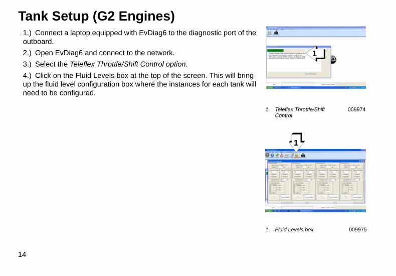
Tank Setup (G2 Engines)1.) Connect a laptop equipped with EvDiag6 to the diagnostic port of the outboard.
2.) Open EvDiag6 and connect to the network.
3.) Select the Teleflex Throttle/Shift Control option.
4.) Click on the Fluid Levels box at the top of the screen. This will bring up the fluid level configuration box where the instances for each tank will need to be configured.
14
1. Teleflex Throttle/Shift Control
009974
1. Fluid Levels box 009975
1
1
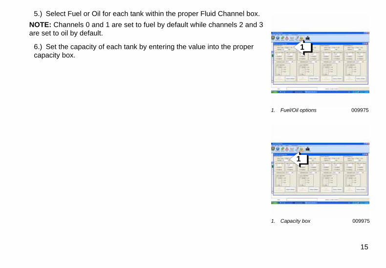
5.) Select Fuel or Oil for each tank within the proper Fluid Channel box.
NOTE: Channels 0 and 1 are set to fuel by default while channels 2 and 3are set to oil by default.
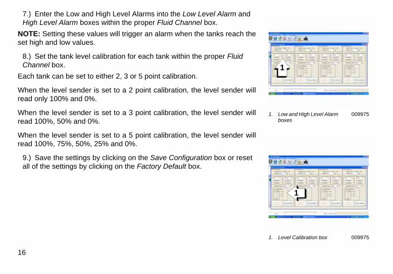
6.) Set the capacity of each tank by entering the value into the proper capacity box.
1. Fuel/Oil options 009975
1. Capacity box 009975
1
1
15
1. Low and High Level Alarm boxes
009975
1. Level Calibration box 009975
1
1
7.) Enter the Low and High Level Alarms into the Low Level Alarm and High Level Alarm boxes within the proper Fluid Channel box.
NOTE: Setting these values will trigger an alarm when the tanks reach theset high and low values.
8.) Set the tank level calibration for each tank within the proper Fluid Channel box.
Each tank can be set to either 2, 3 or 5 point calibration.
When the level sender is set to a 2 point calibration, the level sender willread only 100% and 0%.
When the level sender is set to a 3 point calibration, the level sender willread 100%, 50% and 0%.
When the level sender is set to a 5 point calibration, the level sender willread 100%, 75%, 50%, 25% and 0%.
9.) Save the settings by clicking on the Save Configuration box or reset all of the settings by clicking on the Factory Default box.
16
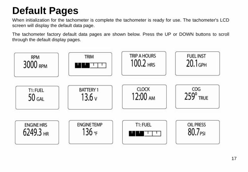
Default PagesWhen initialization for the tachometer is complete the tachometer is ready for use. The tachometer's LCDscreen will display the default data page.
The tachometer factory default data pages are shown below. Press the UP or DOWN buttons to scrollthrough the default display pages.
17
Menu OptionsPressing the MODE button once will show the Tachometer Menu Options. These options are
•RESET TOTALIZER: This option resets the total fuel used
•TRIP DATA: This option records engine hours, Fuel Used, Odometer and Fuel Rate
•FUEL LEVEL: This option is used for quick access to add fuel to one of the fuel tanks.
•EDIT MENU: This options is used to make global Tachometer settings and changes
•CONTRAST: This option is used to adjust the Tachometer and Speedometer’s display.
•LIGHTING: This option is used to adjust the lighting level(s).
•DEPTH: This option is used to set the depth of the water alarms (if available).
18
009988
009989
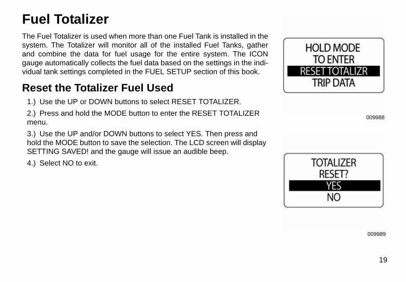
Fuel TotalizerThe Fuel Totalizer is used when more than one Fuel Tank is installed in thesystem. The Totalizer will monitor all of the installed Fuel Tanks, gatherand combine the data for fuel usage for the entire system. The ICONgauge automatically collects the fuel data based on the settings in the indi-vidual tank settings completed in the FUEL SETUP section of this book.
Reset the Totalizer Fuel Used1.) Use the UP or DOWN buttons to select RESET TOTALIZER.
2.) Press and hold the MODE button to enter the RESET TOTALIZER menu.
3.) Use the UP and/or DOWN buttons to select YES. Then press and hold the MODE button to save the selection. The LCD screen will display SETTING SAVED! and the gauge will issue an audible beep.
4.) Select NO to exit.
19
009990
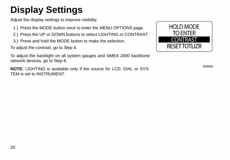
Display SettingsAdjust the display settings to improve visibility.
1.) Press the MODE button once to enter the MENU OPTIONS page.
2.) Press the UP or DOWN buttons to select LIGHTING or CONTRAST.
3.) Press and hold the MODE button to make the selection.
To adjust the contrast, go to Step 4.
To adjust the backlight on all system gauges and NMEA 2000 backbonenetwork devices, go to Step 6.
NOTE: LIGHTING is available only if the source for LCD, DIAL or SYS-TEM is set to INSTRUMENT.
20
009991
009992
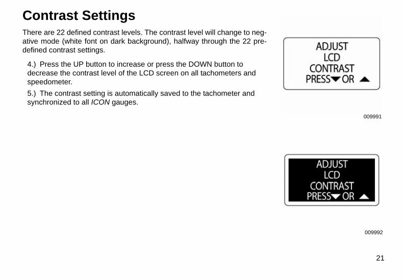
Contrast SettingsThere are 22 defined contrast levels. The contrast level will change to neg-ative mode (white font on dark background), halfway through the 22 pre-defined contrast settings.
4.) Press the UP button to increase or press the DOWN button to decrease the contrast level of the LCD screen on all tachometers and speedometer.
5.) The contrast setting is automatically saved to the tachometer and synchronized to all ICON gauges.
21
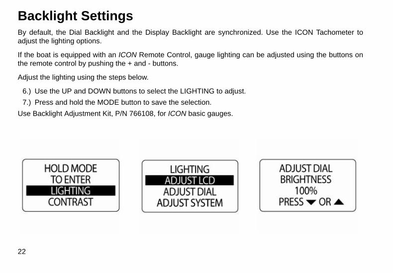
Backlight SettingsBy default, the Dial Backlight and the Display Backlight are synchronized. Use the ICON Tachometer toadjust the lighting options.
If the boat is equipped with an ICON Remote Control, gauge lighting can be adjusted using the buttons onthe remote control by pushing the + and - buttons.
Adjust the lighting using the steps below.
6.) Use the UP and DOWN buttons to select the LIGHTING to adjust.
7.) Press and hold the MODE button to save the selection.
Use Backlight Adjustment Kit, P/N 766108, for ICON basic gauges.
22
009996
009997
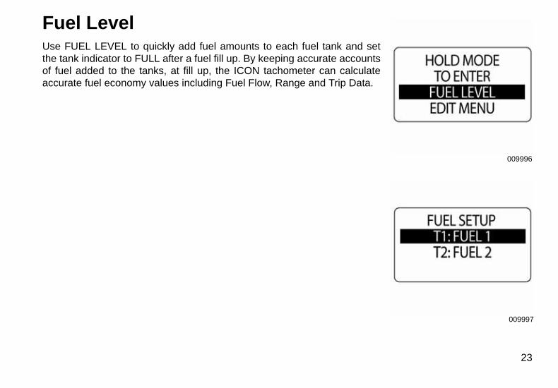
Fuel LevelUse FUEL LEVEL to quickly add fuel amounts to each fuel tank and setthe tank indicator to FULL after a fuel fill up. By keeping accurate accountsof fuel added to the tanks, at fill up, the ICON tachometer can calculateaccurate fuel economy values including Fuel Flow, Range and Trip Data.
23
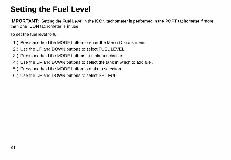
Setting the Fuel LevelIMPORTANT: Setting the Fuel Level in the ICON tachometer is performed in the PORT tachometer if morethan one ICON tachometer is in use.
To set the fuel level to full:
1.) Press and hold the MODE button to enter the Menu Options menu.
2.) Use the UP and DOWN buttons to select FUEL LEVEL.
3.) Press and hold the MODE buttons to make a selection.
4.) Use the UP and DOWN buttons to select the tank in which to add fuel.
5.) Press and hold the MODE button to make a selection.
6.) Use the UP and DOWN buttons to select SET FULL
24
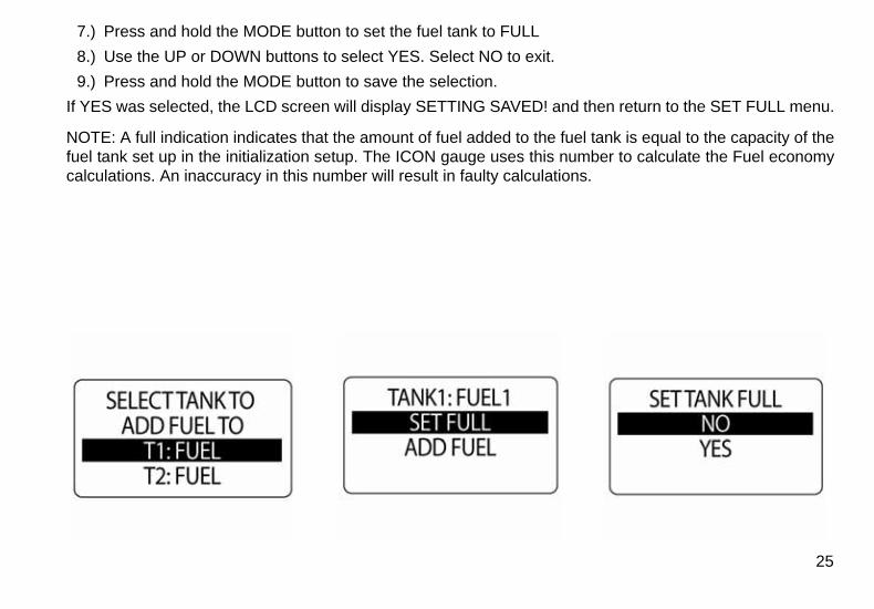
7.) Press and hold the MODE button to set the fuel tank to FULL
8.) Use the UP or DOWN buttons to select YES. Select NO to exit.
9.) Press and hold the MODE button to save the selection.
If YES was selected, the LCD screen will display SETTING SAVED! and then return to the SET FULL menu.
NOTE: A full indication indicates that the amount of fuel added to the fuel tank is equal to the capacity of thefuel tank set up in the initialization setup. The ICON gauge uses this number to calculate the Fuel economycalculations. An inaccuracy in this number will result in faulty calculations.
25
010001
010002
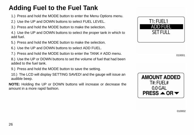
Adding Fuel to the Fuel Tank1.) Press and hold the MODE button to enter the Menu Options menu.
2.) Use the UP and DOWN buttons to select FUEL LEVEL.
3.) Press and hold the MODE button to make the selection.
4.) Use the UP and DOWN buttons to select the proper tank in which to add fuel.
5.) Press and hold the MODE button to make the selection.
6.) Use the UP and DOWN buttons to select ADD FUEL.
7.) Press and hold the MODE button to enter the TANK # ADD menu.
8.) Use the UP or DOWN buttons to set the volume of fuel that had been added to the fuel tank.
9.) Press and hold the MODE button to save the setting.
10.) The LCD will display SETTING SAVED! and the gauge will issue an audible beep.
NOTE: Holding the UP or DOWN buttons will increase or decrease theamount in a more rapid fashion.
26
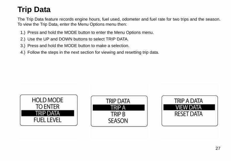
Trip DataThe Trip Data feature records engine hours, fuel used, odometer and fuel rate for two trips and the season.To view the Trip Data, enter the Menu Options menu then:
1.) Press and hold the MODE button to enter the Menu Options menu.
2.) Use the UP and DOWN buttons to select TRIP DATA.
3.) Press and hold the MODE button to make a selection.
4.) Follow the steps in the next section for viewing and resetting trip data.
27
010006
010007
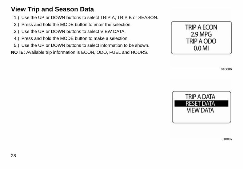
View Trip and Season Data1.) Use the UP or DOWN buttons to select TRIP A, TRIP B or SEASON.
2.) Press and hold the MODE button to enter the selection.
3.) Use the UP or DOWN buttons to select VIEW DATA.
4.) Press and hold the MODE button to make a selection.
5.) Use the UP or DOWN buttons to select information to be shown.
NOTE: Available trip information is ECON, ODO, FUEL and HOURS.
28
010008
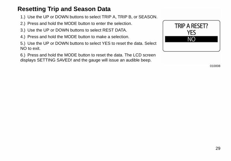
Resetting Trip and Season Data1.) Use the UP or DOWN buttons to select TRIP A, TRIP B, or SEASON.
2.) Press and hold the MODE button to enter the selection.
3.) Use the UP or DOWN buttons to select REST DATA.
4.) Press and hold the MODE button to make a selection.
5.) Use the UP or DOWN buttons to select YES to reset the data. Select NO to exit.
6.) Press and hold the MODE button to reset the data. The LCD screen displays SETTING SAVED! and the gauge will issue an audible beep.
29

30

TachometerOperation
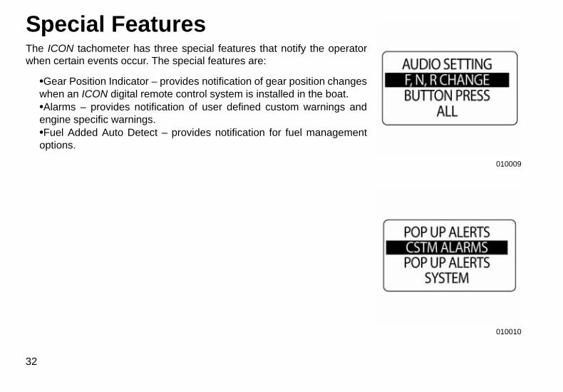
Special FeaturesThe ICON tachometer has three special features that notify the operatorwhen certain events occur. The special features are:
•Gear Position Indicator – provides notification of gear position changeswhen an ICON digital remote control system is installed in the boat.•Alarms – provides notification of user defined custom warnings andengine specific warnings.•Fuel Added Auto Detect – provides notification for fuel managementoptions.
32
010009
010010
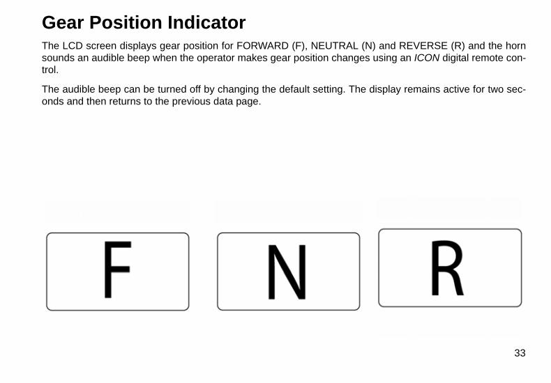
Gear Position IndicatorThe LCD screen displays gear position for FORWARD (F), NEUTRAL (N) and REVERSE (R) and the hornsounds an audible beep when the operator makes gear position changes using an ICON digital remote con-trol.
The audible beep can be turned off by changing the default setting. The display remains active for two sec-onds and then returns to the previous data page.
33
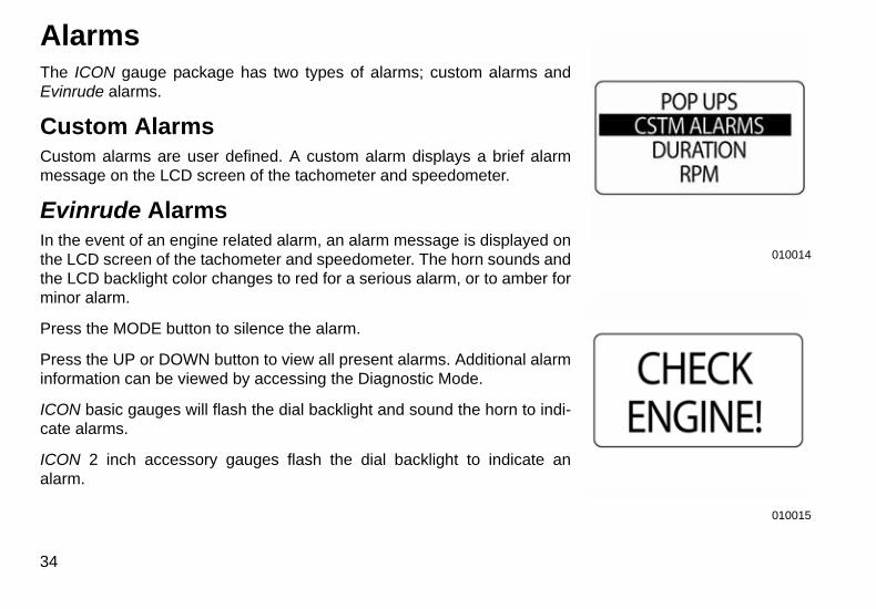
AlarmsThe ICON gauge package has two types of alarms; custom alarms andEvinrude alarms.
Custom AlarmsCustom alarms are user defined. A custom alarm displays a brief alarmmessage on the LCD screen of the tachometer and speedometer.
Evinrude AlarmsIn the event of an engine related alarm, an alarm message is displayed onthe LCD screen of the tachometer and speedometer. The horn sounds andthe LCD backlight color changes to red for a serious alarm, or to amber forminor alarm.
Press the MODE button to silence the alarm.
Press the UP or DOWN button to view all present alarms. Additional alarminformation can be viewed by accessing the Diagnostic Mode.
ICON basic gauges will flash the dial backlight and sound the horn to indi-cate alarms.
ICON 2 inch accessory gauges flash the dial backlight to indicate analarm.
34
010014
010015
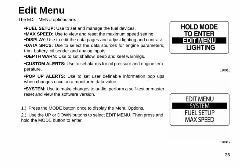
Edit MenuThe EDIT MENU options are:
•FUEL SETUP: Use to set and manage the fuel devices.•MAX SPEED: Use to view and reset the maximum speed setting.•DISPLAY: Use to edit the data pages and adjust lighting and contrast.•DATA SRCS: Use to select the data sources for engine parameters,trim, battery, oil sender and analog inputs.•DEPTH WARN: Use to set shallow, deep and keel warnings.
•CUSTOM ALERTS: Use to set alarms for oil pressure and engine tem-perature.
•POP UP ALERTS: Use to set user definable information pop upswhen changes occur in a monitored data value.
•SYSTEM: Use to make changes to audio, perform a self-test or masterreset and view the software version.
1.) Press the MODE button once to display the Menu Options.
2.) Use the UP or DOWN buttons to select EDIT MENU. Then press and hold the MODE button to enter.
010016
010017
35
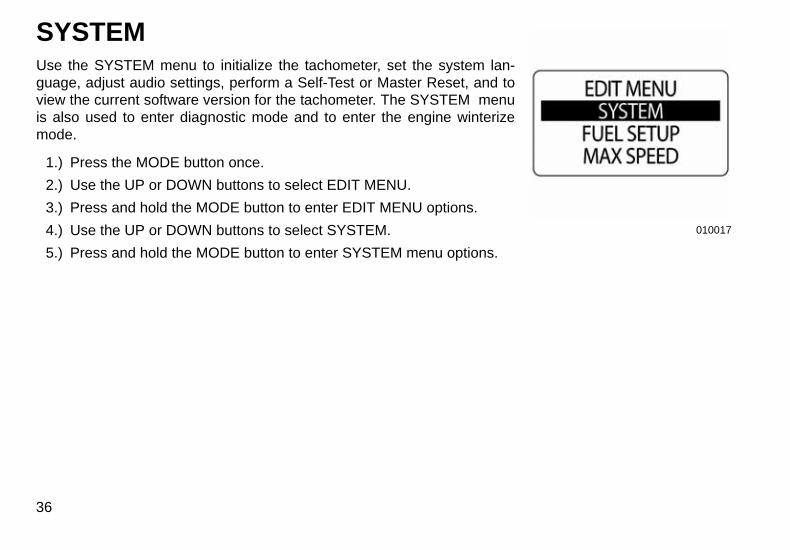
SYSTEMUse the SYSTEM menu to initialize the tachometer, set the system lan-guage, adjust audio settings, perform a Self-Test or Master Reset, and toview the current software version for the tachometer. The SYSTEM menuis also used to enter diagnostic mode and to enter the engine winterizemode.
1.) Press the MODE button once.
2.) Use the UP or DOWN buttons to select EDIT MENU.
3.) Press and hold the MODE button to enter EDIT MENU options.
4.) Use the UP or DOWN buttons to select SYSTEM.
5.) Press and hold the MODE button to enter SYSTEM menu options.
36
010017
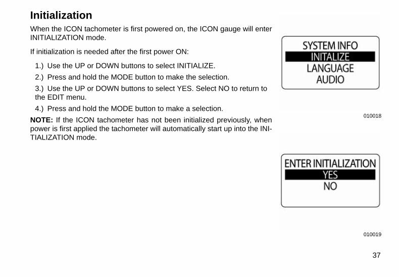
InitializationWhen the ICON tachometer is first powered on, the ICON gauge will enterINITIALIZATION mode.
If initialization is needed after the first power ON:
1.) Use the UP or DOWN buttons to select INITIALIZE.
2.) Press and hold the MODE button to make the selection.
3.) Use the UP or DOWN buttons to select YES. Select NO to return to the EDIT menu.
4.) Press and hold the MODE button to make a selection.
NOTE: If the ICON tachometer has not been initialized previously, whenpower is first applied the tachometer will automatically start up into the INI-TIALIZATION mode.
010018
010019
37
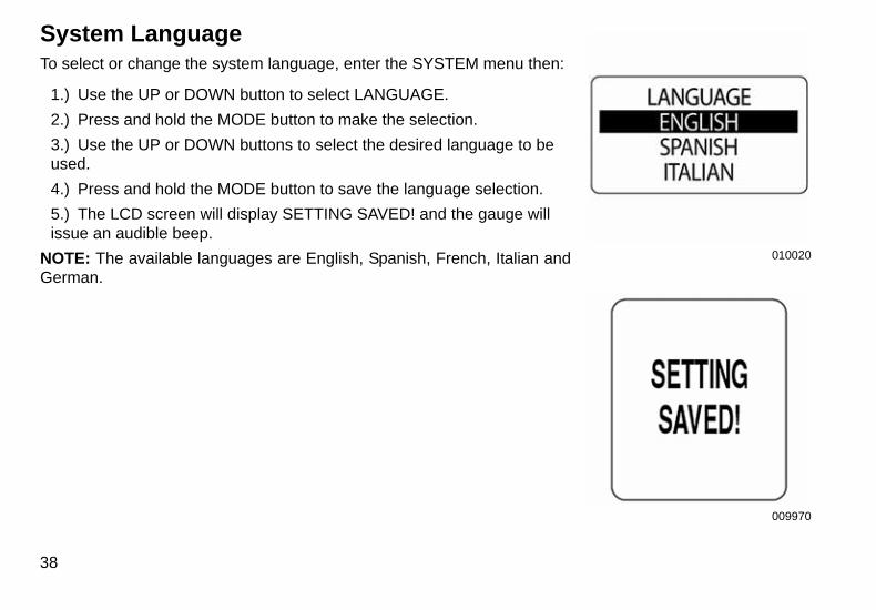
System LanguageTo select or change the system language, enter the SYSTEM menu then:
1.) Use the UP or DOWN button to select LANGUAGE.
2.) Press and hold the MODE button to make the selection.
3.) Use the UP or DOWN buttons to select the desired language to be used.
4.) Press and hold the MODE button to save the language selection.
5.) The LCD screen will display SETTING SAVED! and the gauge will issue an audible beep.
NOTE: The available languages are English, Spanish, French, Italian andGerman.
38
010020
009970
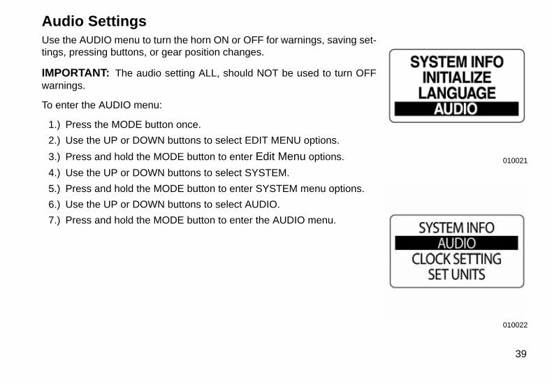
Audio SettingsUse the AUDIO menu to turn the horn ON or OFF for warnings, saving set-tings, pressing buttons, or gear position changes.
IMPORTANT: The audio setting ALL, should NOT be used to turn OFFwarnings.
To enter the AUDIO menu:
1.) Press the MODE button once.
2.) Use the UP or DOWN buttons to select EDIT MENU options.
3.) Press and hold the MODE button to enter Edit Menu options.
4.) Use the UP or DOWN buttons to select SYSTEM.
5.) Press and hold the MODE button to enter SYSTEM menu options.
6.) Use the UP or DOWN buttons to select AUDIO.
7.) Press and hold the MODE button to enter the AUDIO menu.
010021
010022
39
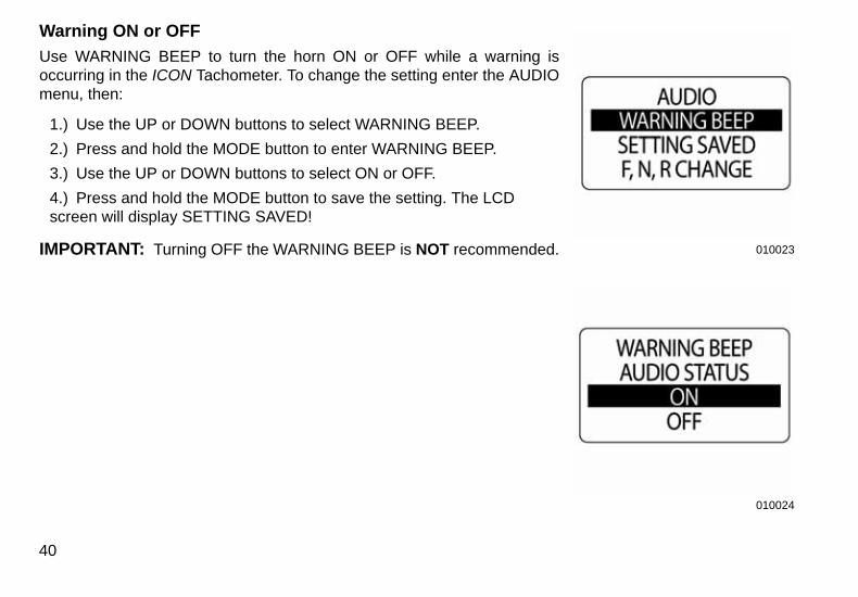
Warning ON or OFF
Use WARNING BEEP to turn the horn ON or OFF while a warning isoccurring in the ICON Tachometer. To change the setting enter the AUDIOmenu, then:
1.) Use the UP or DOWN buttons to select WARNING BEEP.
2.) Press and hold the MODE button to enter WARNING BEEP.
3.) Use the UP or DOWN buttons to select ON or OFF.
4.) Press and hold the MODE button to save the setting. The LCD screen will display SETTING SAVED!
IMPORTANT: Turning OFF the WARNING BEEP is NOT recommended.
40
010023
010024
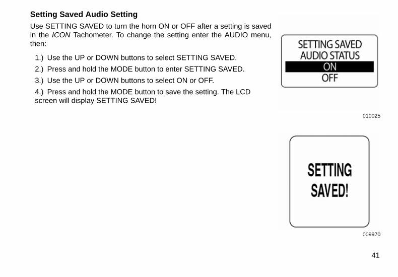
Setting Saved Audio Setting
Use SETTING SAVED to turn the horn ON or OFF after a setting is savedin the ICON Tachometer. To change the setting enter the AUDIO menu,then:
1.) Use the UP or DOWN buttons to select SETTING SAVED.
2.) Press and hold the MODE button to enter SETTING SAVED.
3.) Use the UP or DOWN buttons to select ON or OFF.
4.) Press and hold the MODE button to save the setting. The LCD screen will display SETTING SAVED!
010025
009970
41
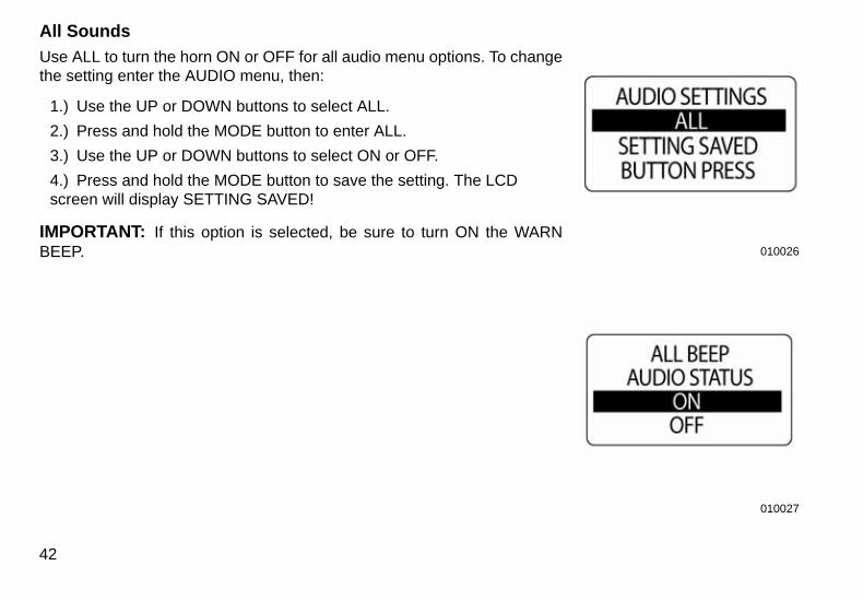
All Sounds
Use ALL to turn the horn ON or OFF for all audio menu options. To changethe setting enter the AUDIO menu, then:
1.) Use the UP or DOWN buttons to select ALL.
2.) Press and hold the MODE button to enter ALL.
3.) Use the UP or DOWN buttons to select ON or OFF.
4.) Press and hold the MODE button to save the setting. The LCD screen will display SETTING SAVED!
IMPORTANT: If this option is selected, be sure to turn ON the WARNBEEP.
42
010026
010027
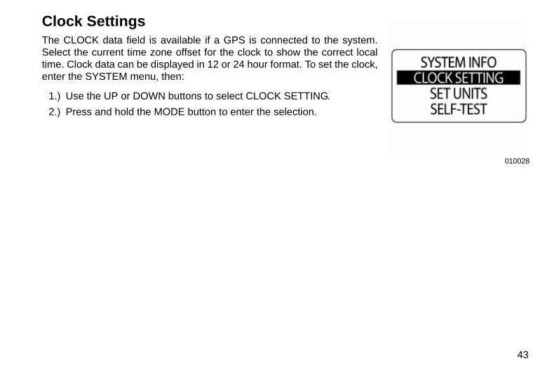
Clock SettingsThe CLOCK data field is available if a GPS is connected to the system.Select the current time zone offset for the clock to show the correct localtime. Clock data can be displayed in 12 or 24 hour format. To set the clock,enter the SYSTEM menu, then:
1.) Use the UP or DOWN buttons to select CLOCK SETTING.
2.) Press and hold the MODE button to enter the selection.
010028
43
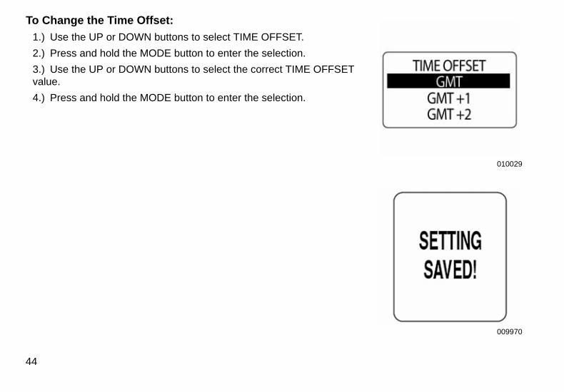
To Change the Time Offset:
1.) Use the UP or DOWN buttons to select TIME OFFSET.
2.) Press and hold the MODE button to enter the selection.
3.) Use the UP or DOWN buttons to select the correct TIME OFFSET value.
4.) Press and hold the MODE button to enter the selection.
44
010029
009970
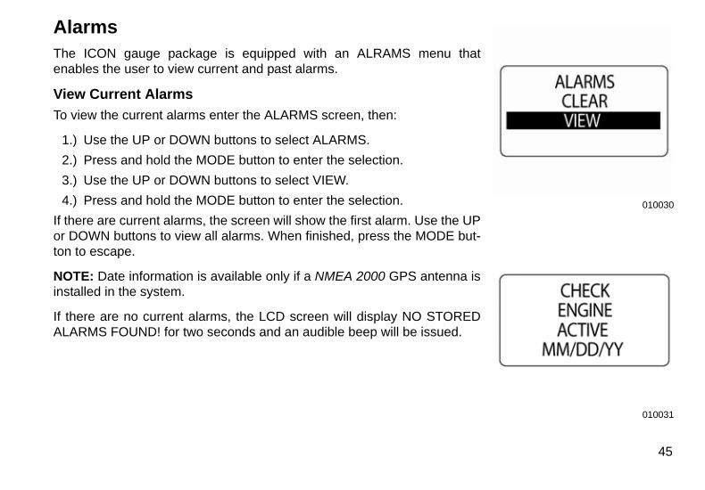
AlarmsThe ICON gauge package is equipped with an ALRAMS menu thatenables the user to view current and past alarms.
View Current Alarms
To view the current alarms enter the ALARMS screen, then:
1.) Use the UP or DOWN buttons to select ALARMS.
2.) Press and hold the MODE button to enter the selection.
3.) Use the UP or DOWN buttons to select VIEW.
4.) Press and hold the MODE button to enter the selection.
If there are current alarms, the screen will show the first alarm. Use the UPor DOWN buttons to view all alarms. When finished, press the MODE but-ton to escape.
NOTE: Date information is available only if a NMEA 2000 GPS antenna isinstalled in the system.
If there are no current alarms, the LCD screen will display NO STOREDALARMS FOUND! for two seconds and an audible beep will be issued.
010030
010031
45
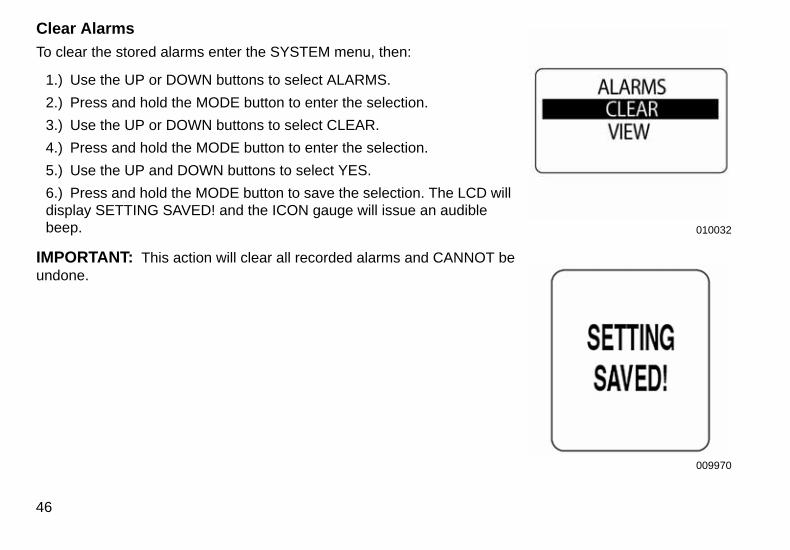
Clear Alarms
To clear the stored alarms enter the SYSTEM menu, then:
1.) Use the UP or DOWN buttons to select ALARMS.
2.) Press and hold the MODE button to enter the selection.
3.) Use the UP or DOWN buttons to select CLEAR.
4.) Press and hold the MODE button to enter the selection.
5.) Use the UP and DOWN buttons to select YES.
6.) Press and hold the MODE button to save the selection. The LCD will display SETTING SAVED! and the ICON gauge will issue an audible beep.
IMPORTANT: This action will clear all recorded alarms and CANNOT beundone.
46
010032
009970
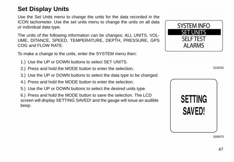
Set Display UnitsUse the Set Units menu to change the units for the data recorded in theICON tachometer. Use the set units menu to change the units on all dataor individual data type.
The units of the following information can be changes; ALL UNITS, VOL-UME, DITANCE, SPEED, TEMPERATURE, DEPTH, PRESSURE, GPSCOG and FLOW RATE.
To make a change to the units, enter the SYSTEM menu then:
1.) Use the UP or DOWN buttons to select SET UNITS.
2.) Press and hold the MODE button to enter the selection.
3.) Use the UP or DOWN buttons to select the data type to be changed.
4.) Press and hold the MODE button to enter the selection.
5.) Use the UP or DOWN buttons to select the desired units type.
6.) Press and hold the MODE button to save the selection. The LCD screen will display SETTING SAVED! and the gauge will issue an audible beep.
010033
009970
47

Self TestUse the SELF-TEST feature to test the ICON gauge package is communi-cating with the Tachometer. To perform a self-test, enter the SYSTEMmenu, then:
1.) Use the UP or DOWN buttons to select SELF-TEST.
2.) Press and hold the MODE button to enter the SELF-TEST.
3.) Use the UP or DOWN buttons to select YES.
4.) Press and hold the MODE button to begin the SELF-TEST.
During the SELF-TEST:
•The tachometer will run through a series of scripted self-test programsdesigned to test the operation of the tachometer.•The pointer will move through a series of angles and the buzzer willbeep.•When finished, the tachometer LCD will display APP SELF TESTCOMPLETE.•Once complete, the display will return to normal operation.
48
010034
010035
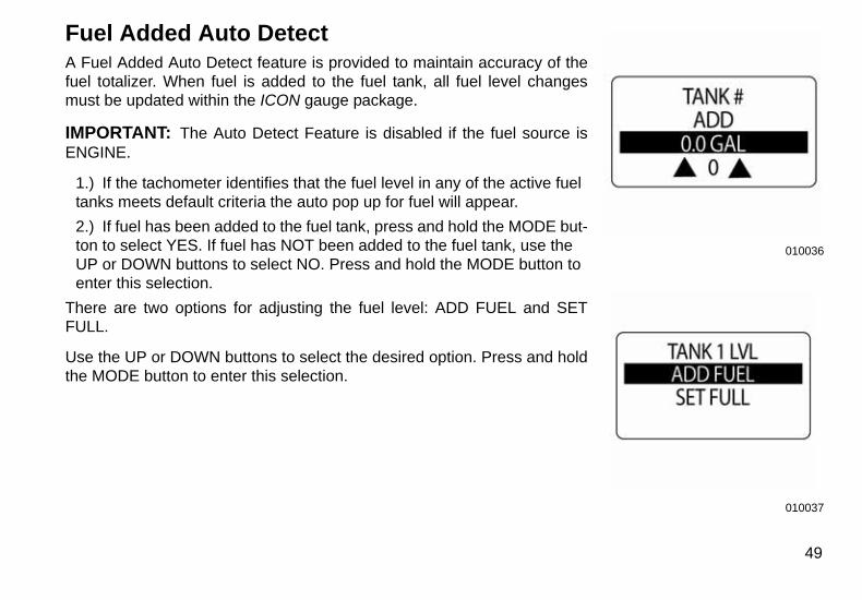
Fuel Added Auto DetectA Fuel Added Auto Detect feature is provided to maintain accuracy of thefuel totalizer. When fuel is added to the fuel tank, all fuel level changesmust be updated within the ICON gauge package.
IMPORTANT: The Auto Detect Feature is disabled if the fuel source isENGINE.
1.) If the tachometer identifies that the fuel level in any of the active fuel tanks meets default criteria the auto pop up for fuel will appear.
2.) If fuel has been added to the fuel tank, press and hold the MODE but-ton to select YES. If fuel has NOT been added to the fuel tank, use the UP or DOWN buttons to select NO. Press and hold the MODE button to enter this selection.
There are two options for adjusting the fuel level: ADD FUEL and SETFULL.
Use the UP or DOWN buttons to select the desired option. Press and holdthe MODE button to enter this selection.
010036
010037
49
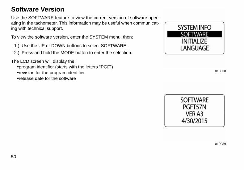
Software VersionUse the SOFTWARE feature to view the current version of software oper-ating in the tachometer. This information may be useful when communicat-ing with technical support.
To view the software version, enter the SYSTEM menu, then:
1.) Use the UP or DOWN buttons to select SOFTWARE.
2.) Press and hold the MODE button to enter the selection.
The LCD screen will display the:•program identifier (starts with the letters “PGF”)•revision for the program identifier•release date for the software
50
010038
010039

Master ResetUse the MASTER RESET feature to reset the tachometer to the factorydefault settings.
To perform a master reset, enter the SYSTEM menu, then:
1.) Use the UP or DOWN buttons to select MSTR RESET.
2.) Press and hold the MODE button to enter the selection.
3.) Use the UP or DOWN buttons to select YES or NO.
4.) Press and hold the MODE button to enter the selection.
If NO is selected the gauge will exit to the SYSTEM menu. If YES isselected continue with the next step.
A warning message will display for five seconds and the horn will beepthree times. Next, the LCD screen will display the message: CONTINUEWITH RESET?
5.) Use the UP or DOWN buttons to select YES or NO.
6.) Press and hold the MODE button to enter the selection.
If NO is selected, the gauge will exit to the SYSTEM menu.
If YES is selected, the ICON gauge will be reset to the factory default set-tings.
010040
010041
51
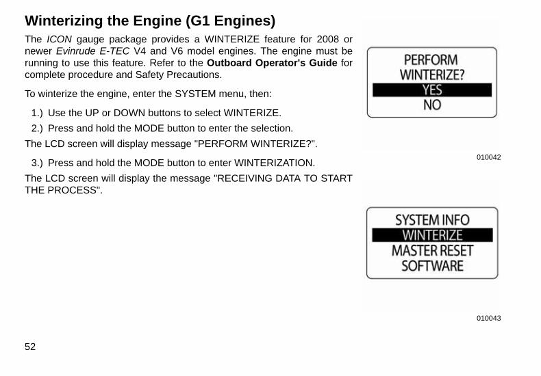
Winterizing the Engine (G1 Engines)The ICON gauge package provides a WINTERIZE feature for 2008 ornewer Evinrude E-TEC V4 and V6 model engines. The engine must berunning to use this feature. Refer to the Outboard Operator's Guide forcomplete procedure and Safety Precautions.
To winterize the engine, enter the SYSTEM menu, then:
1.) Use the UP or DOWN buttons to select WINTERIZE.
2.) Press and hold the MODE button to enter the selection.
The LCD screen will display message "PERFORM WINTERIZE?".
3.) Press and hold the MODE button to enter WINTERIZATION.
The LCD screen will display the message "RECEIVING DATA TO STARTTHE PROCESS".
52
010042
010043

4.) Engage NEUTRAL only button on throttle and advance the THROTTLE ONLY to at least 50%, when prompted.
The LCD screen will display "WINTERIZE IN PROGRESS".
When complete the LCD screen will display WINTERIZE COMPLETE.
Do not adjust throttle or engine until winterization is complete and the engine has shut OFF.
5.) Repeat these steps from each ICON PRO tachometer for all other engines in the system.
53
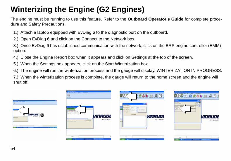
Winterizing the Engine (G2 Engines)The engine must be running to use this feature. Refer to the Outboard Operator's Guide for complete proce-dure and Safety Precautions.
1.) Attach a laptop equipped with EvDiag 6 to the diagnostic port on the outboard.
2.) Open EvDiag 6 and click on the Connect to the Network box.
3.) Once EvDiag 6 has established communication with the network, click on the BRP engine controller (EMM) option.
4.) Close the Engine Report box when it appears and click on Settings at the top of the screen.
5.) When the Settings box appears, click on the Start Winterization box.
6.) The engine will run the winterization process and the gauge will display, WINTERIZATION IN PROGRESS.
7.) When the winterization process is complete, the gauge will return to the home screen and the engine will shut off.
54
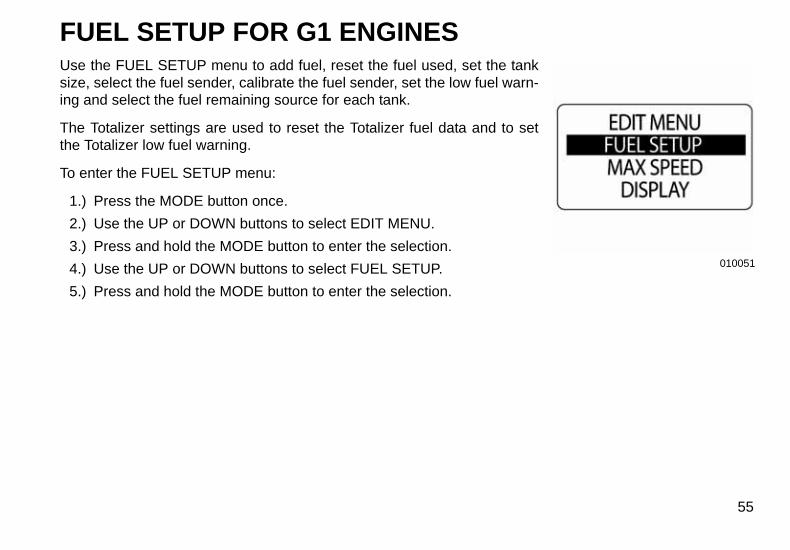
FUEL SETUP FOR G1 ENGINESUse the FUEL SETUP menu to add fuel, reset the fuel used, set the tanksize, select the fuel sender, calibrate the fuel sender, set the low fuel warn-ing and select the fuel remaining source for each tank.
The Totalizer settings are used to reset the Totalizer fuel data and to setthe Totalizer low fuel warning.
To enter the FUEL SETUP menu:
1.) Press the MODE button once.
2.) Use the UP or DOWN buttons to select EDIT MENU.
3.) Press and hold the MODE button to enter the selection.
4.) Use the UP or DOWN buttons to select FUEL SETUP.
5.) Press and hold the MODE button to enter the selection.
010051
55
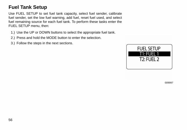
Fuel Tank SetupUse FUEL SETUP to set fuel tank capacity, select fuel sender, calibratefuel sender, set the low fuel warning, add fuel, reset fuel used, and selectfuel remaining source for each fuel tank. To perform these tasks enter theFUEL SETUP menu, then:
1.) Use the UP or DOWN buttons to select the appropriate fuel tank.
2.) Press and hold the MODE button to enter the selection.
3.) Follow the steps in the next sections.
56
009997
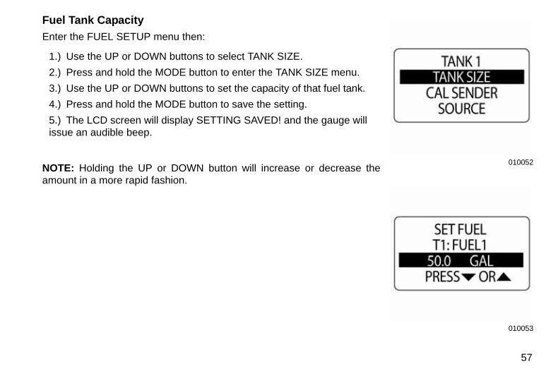
Fuel Tank Capacity
Enter the FUEL SETUP menu then:
1.) Use the UP or DOWN buttons to select TANK SIZE.
2.) Press and hold the MODE button to enter the TANK SIZE menu.
3.) Use the UP or DOWN buttons to set the capacity of that fuel tank.
4.) Press and hold the MODE button to save the setting.
5.) The LCD screen will display SETTING SAVED! and the gauge will issue an audible beep.
NOTE: Holding the UP or DOWN button will increase or decrease theamount in a more rapid fashion.
010052
010053
57
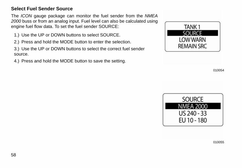
Select Fuel Sender Source
The ICON gauge package can monitor the fuel sender from the NMEA2000 buss or from an analog input. Fuel level can also be calculated usingengine fuel flow data. To set the fuel sender SOURCE:
1.) Use the UP or DOWN buttons to select SOURCE.
2.) Press and hold the MODE button to enter the selection.
3.) Use the UP or DOWN buttons to select the correct fuel sender source.
4.) Press and hold the MODE button to save the setting.
58
010054
010055
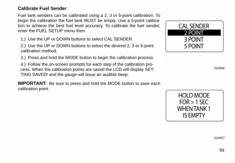
Calibrate Fuel Sender
Fuel tank senders can be calibrated using a 2, 3 or 5-point calibration. Tobegin the calibration the fuel tank MUST be empty. Use a 5-point calibra-tion to achieve the best fuel level accuracy. To calibrate the fuel sender,enter the FUEL SETUP menu then:
1.) Use the UP or DOWN buttons to select CAL SENDER.
2.) Use the UP or DOWN buttons to select the desired 2, 3 or 5-point calibration method.
3.) Press and hold the MODE button to begin the calibration process.
4.) Follow the on-screen prompts for each step of the calibration pro-cess. When the calibration points are saved the LCD will display SET-TING SAVED! and the gauge will issue an audible beep.
IMPORTANT: Be sure to press and hold the MODE button to save eachcalibration point.
010056
010057
59
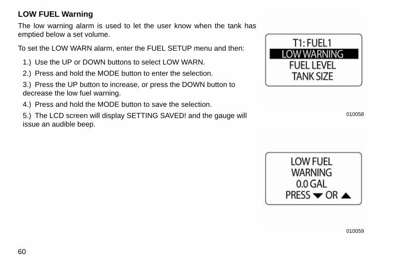
LOW FUEL Warning
The low warning alarm is used to let the user know when the tank hasemptied below a set volume.
To set the LOW WARN alarm, enter the FUEL SETUP menu and then:
1.) Use the UP or DOWN buttons to select LOW WARN.
2.) Press and hold the MODE button to enter the selection.
3.) Press the UP button to increase, or press the DOWN button to decrease the low fuel warning.
4.) Press and hold the MODE button to save the selection.
5.) The LCD screen will display SETTING SAVED! and the gauge will issue an audible beep.
60
010058
010059
1. Fuel/Oil options 009975
1. Capacity box 009975
1
1
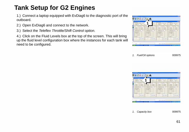
Tank Setup for G2 Engines1.) Connect a laptop equipped with EvDiag6 to the diagnostic port of the outboard.
2.) Open EvDiag6 and connect to the network.
3.) Select the Teleflex Throttle/Shift Control option.
4.) Click on the Fluid Levels box at the top of the screen. This will bring up the fluid level configuration box where the instances for each tank will need to be configured.
61
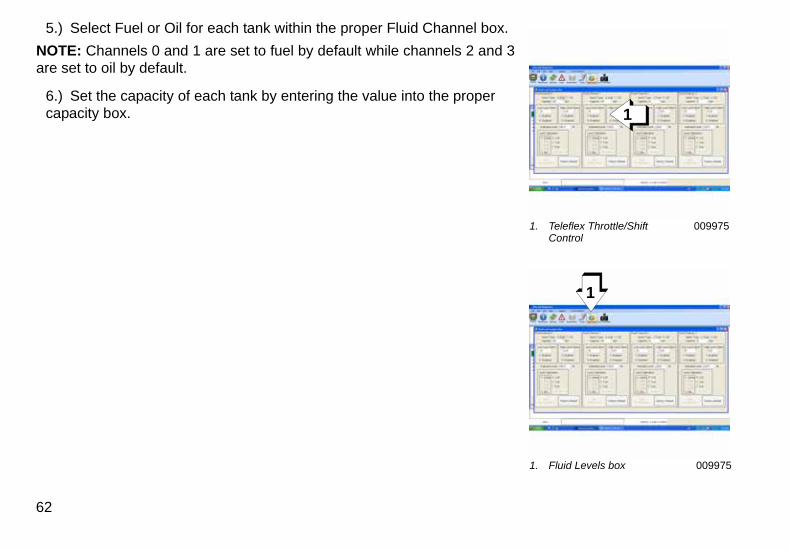
5.) Select Fuel or Oil for each tank within the proper Fluid Channel box.
NOTE: Channels 0 and 1 are set to fuel by default while channels 2 and 3are set to oil by default.
6.) Set the capacity of each tank by entering the value into the proper capacity box.
62
1. Teleflex Throttle/ShiftControl
009975
1. Fluid Levels box 009975
1
1
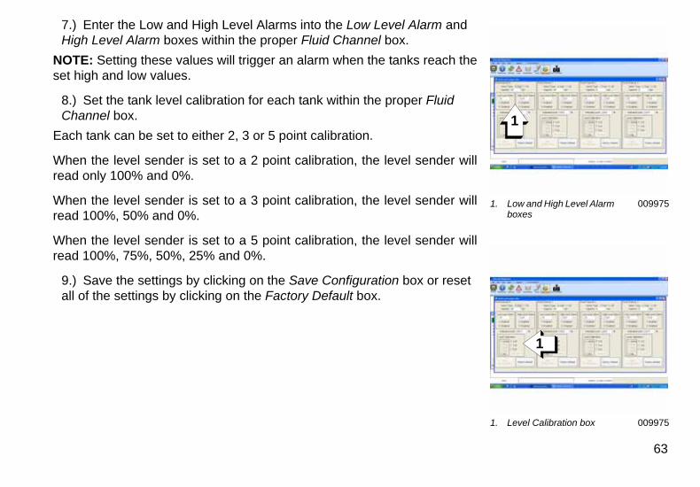
7.) Enter the Low and High Level Alarms into the Low Level Alarm and High Level Alarm boxes within the proper Fluid Channel box.
NOTE: Setting these values will trigger an alarm when the tanks reach theset high and low values.
8.) Set the tank level calibration for each tank within the proper Fluid Channel box.
Each tank can be set to either 2, 3 or 5 point calibration.
When the level sender is set to a 2 point calibration, the level sender willread only 100% and 0%.
When the level sender is set to a 3 point calibration, the level sender willread 100%, 50% and 0%.
When the level sender is set to a 5 point calibration, the level sender willread 100%, 75%, 50%, 25% and 0%.
9.) Save the settings by clicking on the Save Configuration box or reset all of the settings by clicking on the Factory Default box.
1. Low and High Level Alarm boxes
009975
1. Level Calibration box 009975
1
1
63
010060
010061
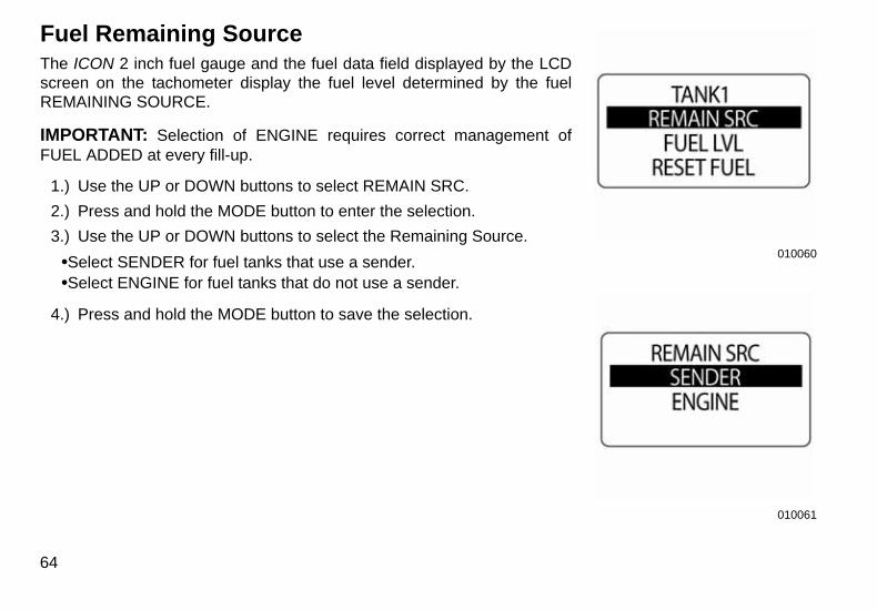
Fuel Remaining SourceThe ICON 2 inch fuel gauge and the fuel data field displayed by the LCDscreen on the tachometer display the fuel level determined by the fuelREMAINING SOURCE.
IMPORTANT: Selection of ENGINE requires correct management ofFUEL ADDED at every fill-up.
1.) Use the UP or DOWN buttons to select REMAIN SRC.
2.) Press and hold the MODE button to enter the selection.
3.) Use the UP or DOWN buttons to select the Remaining Source.
•Select SENDER for fuel tanks that use a sender.•Select ENGINE for fuel tanks that do not use a sender.
4.) Press and hold the MODE button to save the selection.
64
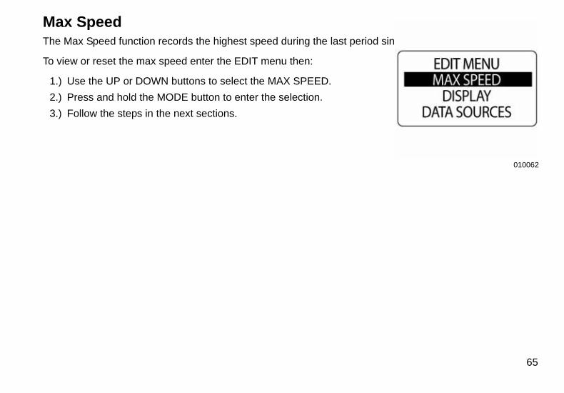
Max SpeedThe Max Speed function records the highest speed during the last period since reset.
To view or reset the max speed enter the EDIT menu then:
1.) Use the UP or DOWN buttons to select the MAX SPEED.
2.) Press and hold the MODE button to enter the selection.
3.) Follow the steps in the next sections.
010062
65
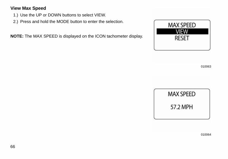
View Max Speed
1.) Use the UP or DOWN buttons to select VIEW.
2.) Press and hold the MODE button to enter the selection.
NOTE: The MAX SPEED is displayed on the ICON tachometer display.
66
010063
010064
010065
009970
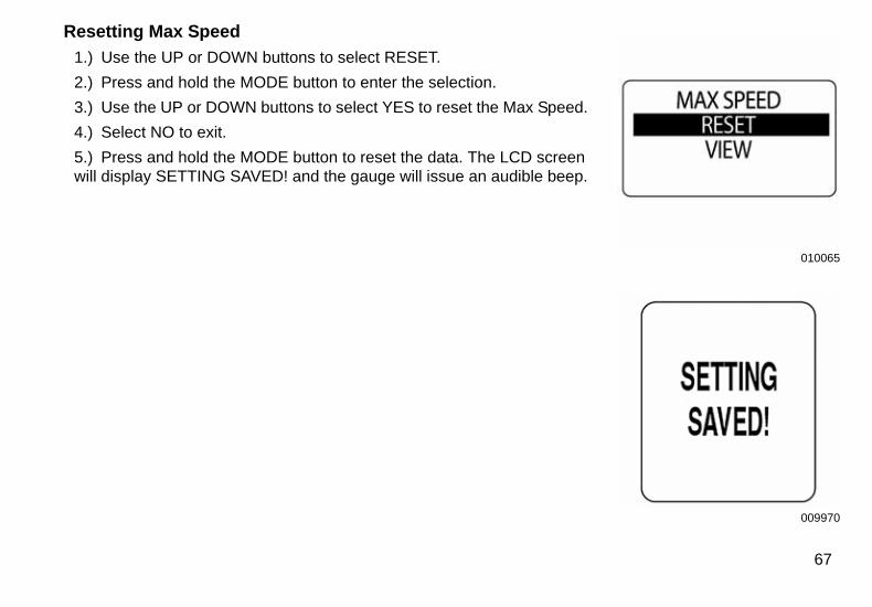
Resetting Max Speed
1.) Use the UP or DOWN buttons to select RESET.
2.) Press and hold the MODE button to enter the selection.
3.) Use the UP or DOWN buttons to select YES to reset the Max Speed.
4.) Select NO to exit.
5.) Press and hold the MODE button to reset the data. The LCD screen will display SETTING SAVED! and the gauge will issue an audible beep.
67
68
Available Data PagesThere are twelve available data pages. It is up to the operator to choose the data pages to be displayed onthe home screens.
For a full list of available data pages to be displayed on the twelve data pages please reference the full list onpage 138 of this manual.
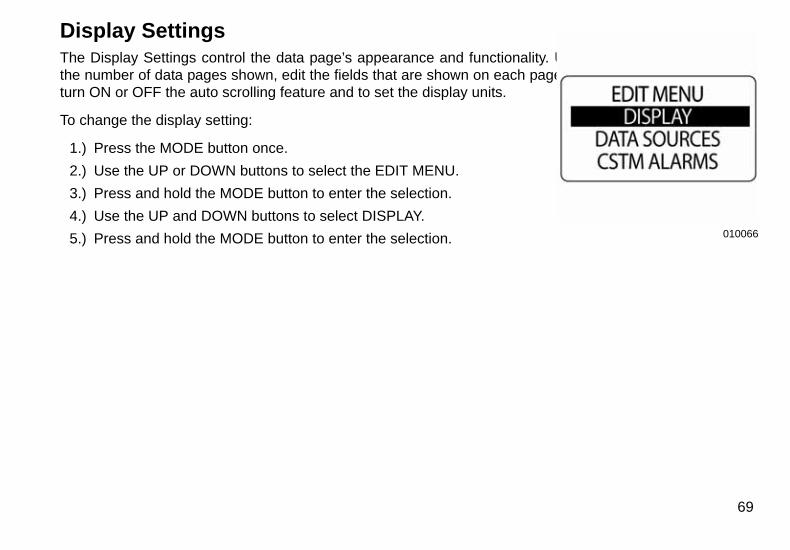
Display SettingsThe Display Settings control the data page’s appearance and functionality. Use the display settings to setthe number of data pages shown, edit the fields that are shown on each page, select the default data page,turn ON or OFF the auto scrolling feature and to set the display units.
To change the display setting:
1.) Press the MODE button once.
2.) Use the UP or DOWN buttons to select the EDIT MENU.
3.) Press and hold the MODE button to enter the selection.
4.) Use the UP and DOWN buttons to select DISPLAY.
5.) Press and hold the MODE button to enter the selection. 010066
69

Set Number of Data PagesThere are twelve default data pages. Each data page can contain up totwo data fields. To add or delete data pages enter the DISPLAY menu,then:
1.) Use the UP or DOWN buttons to select # OF SCREENS.
2.) Press and hold the MODE button to enter the selection.
3.) Press the UP button to increase, or press the DOWN button to decrease the number of data pages.
The minimum number of data pages is one.
Press and hold the MODE button to save the selection. The LCD will display SETTING SAVED! and the gauge will issue an audible beep.
70
010067
010068
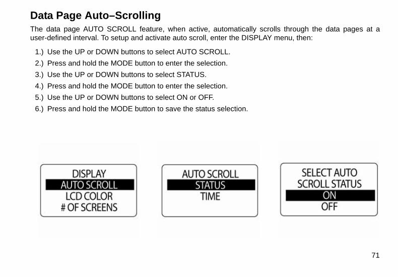
Data Page Auto–ScrollingThe data page AUTO SCROLL feature, when active, automatically scrolls through the data pages at auser-defined interval. To setup and activate auto scroll, enter the DISPLAY menu, then:
1.) Use the UP or DOWN buttons to select AUTO SCROLL.
2.) Press and hold the MODE button to enter the selection.
3.) Use the UP or DOWN buttons to select STATUS.
4.) Press and hold the MODE button to enter the selection.
5.) Use the UP or DOWN buttons to select ON or OFF.
6.) Press and hold the MODE button to save the status selection.
71
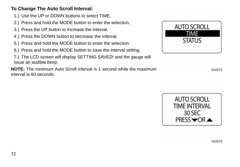
To Change The Auto Scroll Interval:
1.) Use the UP or DOWN buttons to select TIME.
2.) Press and hold the MODE button to enter the selection.
3.) Press the UP button to increase the interval.
4.) Press the DOWN button to decrease the interval.
5.) Press and hold the MODE button to enter the selection.
6.) Press and hold the MODE button to save the interval setting.
7.) The LCD screen will display SETTING SAVED! and the gauge will issue an audible beep.
NOTE: The minimum Auto Scroll interval is 1 second while the maximuminterval is 60 seconds.
72
010072
010073
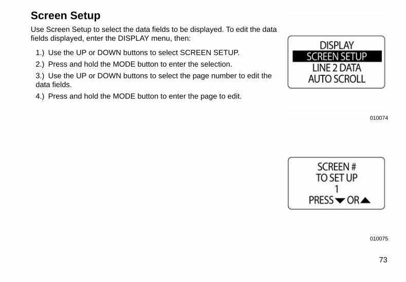
Screen SetupUse Screen Setup to select the data fields to be displayed. To edit the datafields displayed, enter the DISPLAY menu, then:
1.) Use the UP or DOWN buttons to select SCREEN SETUP.
2.) Press and hold the MODE button to enter the selection.
3.) Use the UP or DOWN buttons to select the page number to edit the data fields.
4.) Press and hold the MODE button to enter the page to edit.
010074
010075
73
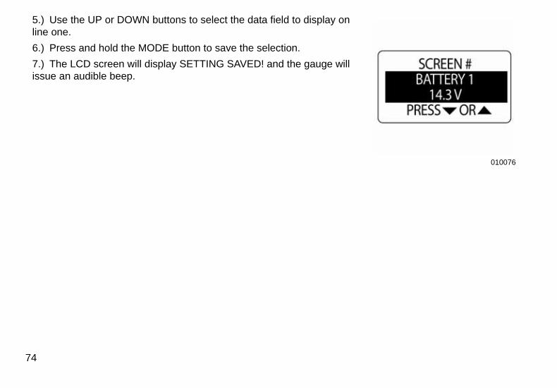
5.) Use the UP or DOWN buttons to select the data field to display on line one.
6.) Press and hold the MODE button to save the selection.
7.) The LCD screen will display SETTING SAVED! and the gauge will issue an audible beep.
74
010076
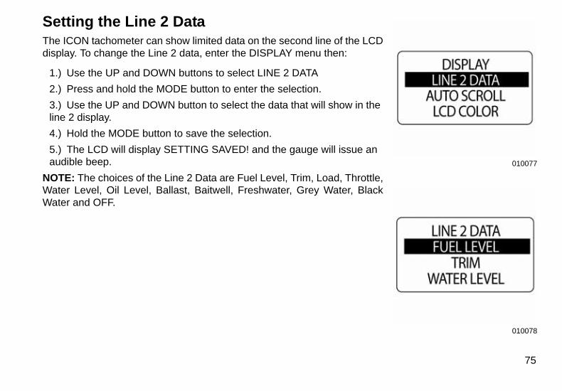
Setting the Line 2 DataThe ICON tachometer can show limited data on the second line of the LCDdisplay. To change the Line 2 data, enter the DISPLAY menu then:
1.) Use the UP and DOWN buttons to select LINE 2 DATA
2.) Press and hold the MODE button to enter the selection.
3.) Use the UP and DOWN button to select the data that will show in the line 2 display.
4.) Hold the MODE button to save the selection.
5.) The LCD will display SETTING SAVED! and the gauge will issue an audible beep.
NOTE: The choices of the Line 2 Data are Fuel Level, Trim, Load, Throttle,Water Level, Oil Level, Ballast, Baitwell, Freshwater, Grey Water, BlackWater and OFF.
010077
010078
75
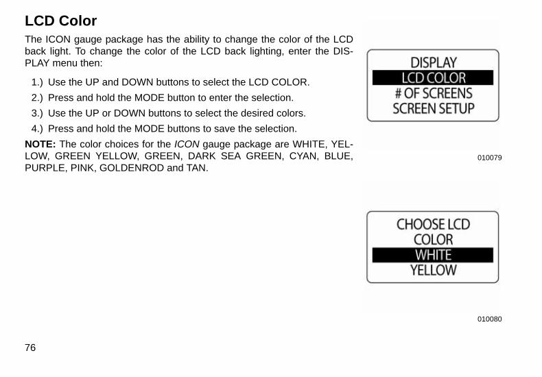
LCD ColorThe ICON gauge package has the ability to change the color of the LCDback light. To change the color of the LCD back lighting, enter the DIS-PLAY menu then:
1.) Use the UP and DOWN buttons to select the LCD COLOR.
2.) Press and hold the MODE button to enter the selection.
3.) Use the UP or DOWN buttons to select the desired colors.
4.) Press and hold the MODE buttons to save the selection.
NOTE: The color choices for the ICON gauge package are WHITE, YEL-LOW, GREEN YELLOW, GREEN, DARK SEA GREEN, CYAN, BLUE,PURPLE, PINK, GOLDENROD and TAN.
76
010079
010080
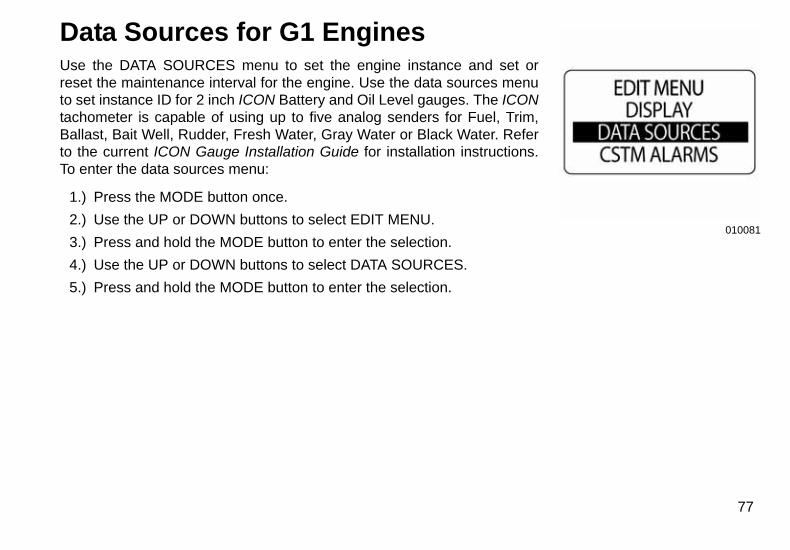
Data Sources for G1 EnginesUse the DATA SOURCES menu to set the engine instance and set orreset the maintenance interval for the engine. Use the data sources menuto set instance ID for 2 inch ICON Battery and Oil Level gauges. The ICONtachometer is capable of using up to five analog senders for Fuel, Trim,Ballast, Bait Well, Rudder, Fresh Water, Gray Water or Black Water. Referto the current ICON Gauge Installation Guide for installation instructions.To enter the data sources menu:
1.) Press the MODE button once.
2.) Use the UP or DOWN buttons to select EDIT MENU.
3.) Press and hold the MODE button to enter the selection.
4.) Use the UP or DOWN buttons to select DATA SOURCES.
5.) Press and hold the MODE button to enter the selection.
010081
77
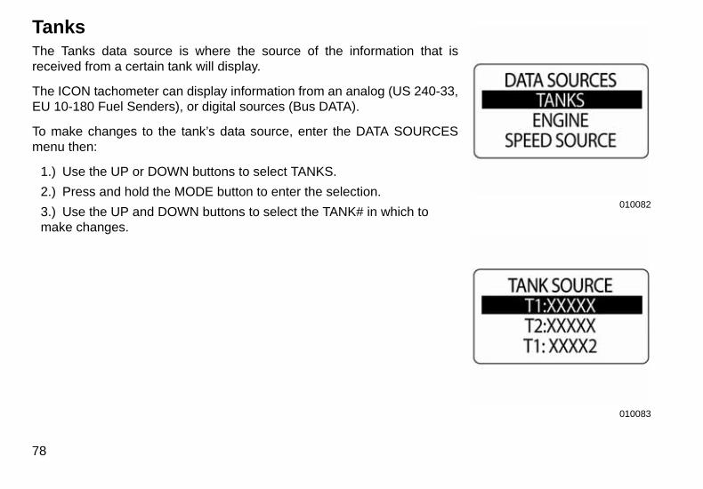
TanksThe Tanks data source is where the source of the information that isreceived from a certain tank will display.
The ICON tachometer can display information from an analog (US 240-33,EU 10-180 Fuel Senders), or digital sources (Bus DATA).
To make changes to the tank’s data source, enter the DATA SOURCESmenu then:
1.) Use the UP or DOWN buttons to select TANKS.
2.) Press and hold the MODE button to enter the selection.
3.) Use the UP and DOWN buttons to select the TANK# in which to make changes.
78
010082
010083
010084
010085
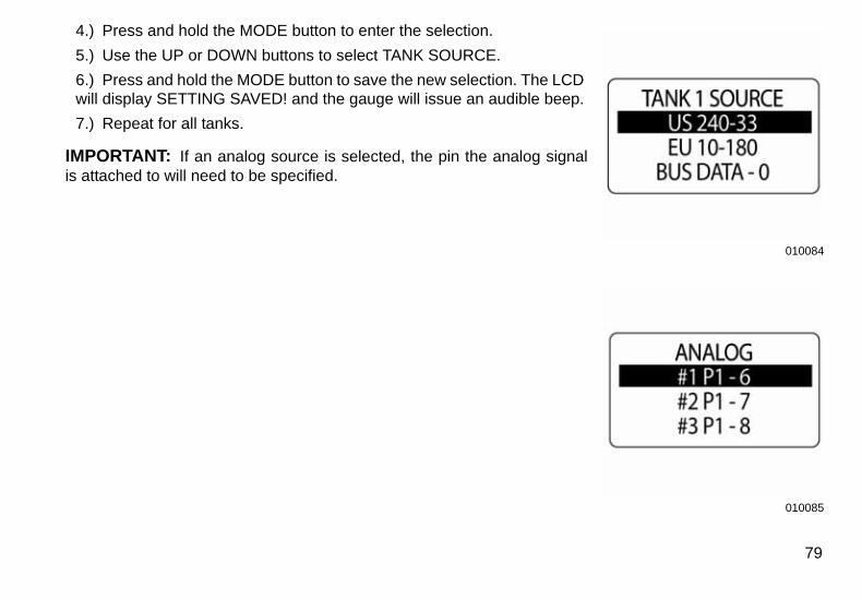
4.) Press and hold the MODE button to enter the selection.
5.) Use the UP or DOWN buttons to select TANK SOURCE.
6.) Press and hold the MODE button to save the new selection. The LCD will display SETTING SAVED! and the gauge will issue an audible beep.
7.) Repeat for all tanks.
IMPORTANT: If an analog source is selected, the pin the analog signalis attached to will need to be specified.
79
010086
010087
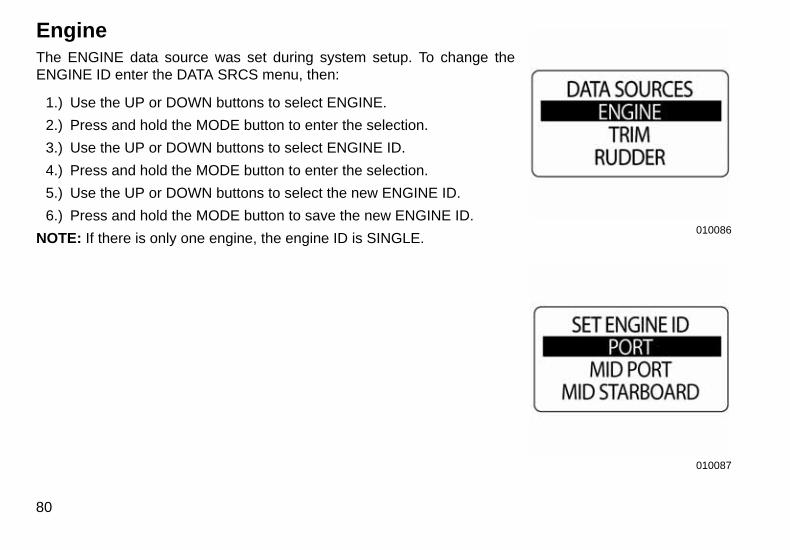
EngineThe ENGINE data source was set during system setup. To change theENGINE ID enter the DATA SRCS menu, then:
1.) Use the UP or DOWN buttons to select ENGINE.
2.) Press and hold the MODE button to enter the selection.
3.) Use the UP or DOWN buttons to select ENGINE ID.
4.) Press and hold the MODE button to enter the selection.
5.) Use the UP or DOWN buttons to select the new ENGINE ID.
6.) Press and hold the MODE button to save the new ENGINE ID.
NOTE: If there is only one engine, the engine ID is SINGLE.
80
010088
010089
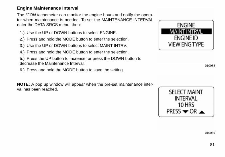
Engine Maintenance Interval
The ICON tachometer can monitor the engine hours and notify the opera-tor when maintenance is needed. To set the MAINTENANCE INTERVALenter the DATA SRCS menu, then:
1.) Use the UP or DOWN buttons to select ENGINE.
2.) Press and hold the MODE button to enter the selection.
3.) Use the UP or DOWN buttons to select MAINT INTRV.
4.) Press and hold the MODE button to enter the selection.
5.) Press the UP button to increase, or press the DOWN button to decrease the Maintenance Interval.
6.) Press and hold the MODE button to save the setting.
NOTE: A pop up window will appear when the pre-set maintenance inter-val has been reached.
81
010090
010091
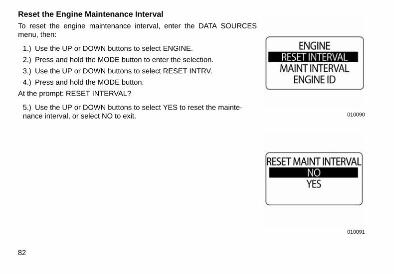
Reset the Engine Maintenance Interval
To reset the engine maintenance interval, enter the DATA SOURCESmenu, then:
1.) Use the UP or DOWN buttons to select ENGINE.
2.) Press and hold the MODE button to enter the selection.
3.) Use the UP or DOWN buttons to select RESET INTRV.
4.) Press and hold the MODE button.
At the prompt: RESET INTERVAL?
5.) Use the UP or DOWN buttons to select YES to reset the mainte-nance interval, or select NO to exit.
82
010092
010093
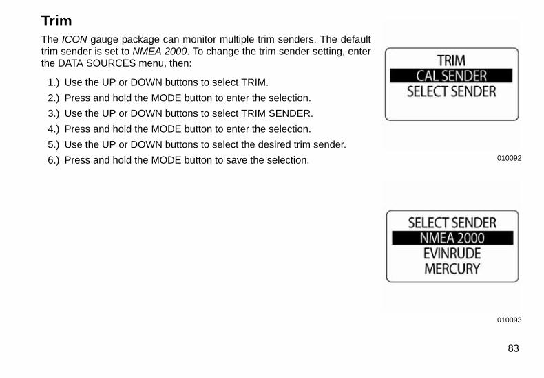
TrimThe ICON gauge package can monitor multiple trim senders. The defaulttrim sender is set to NMEA 2000. To change the trim sender setting, enterthe DATA SOURCES menu, then:
1.) Use the UP or DOWN buttons to select TRIM.
2.) Press and hold the MODE button to enter the selection.
3.) Use the UP or DOWN buttons to select TRIM SENDER.
4.) Press and hold the MODE button to enter the selection.
5.) Use the UP or DOWN buttons to select the desired trim sender.
6.) Press and hold the MODE button to save the selection.
83

Calibrate Trim Sender
Use the ICON tachometer to calibrate the trim sender. To calibrate the trim sender, enter the DATA SRCSmenu, then:
1.) Use the UP or DOWN buttons to select TRIM.
2.) Press and hold the MODE button to enter the selection.
3.) Use the UP or DOWN buttons to select CAL SENDER.
4.) Press and hold the MODE button to enter calibration.
5.) The LCD screen displays: HOLD MODE FOR > 1 SEC WHEN TRIM FULL DOWN,
6.) Make sure the engine is in the full trim DOWN position. Then press and hold the MODE button to save the trim DOWN position.
7.) The LCD screen displays: SETTING SAVED!
84
8.) The LCD Screen displays: HOLD MODE FOR > 1 SEC WHEN TRIM FULL UP
9.) Make sure the engine is in the full trim up position.
10.) Press and hold the MODE button to save the trim up position.
11.) The LCD screen will display SETTING SAVED! and the gauge will issue an audible beep.
12.) The trim sender is now calibrated.
85
010097
009970
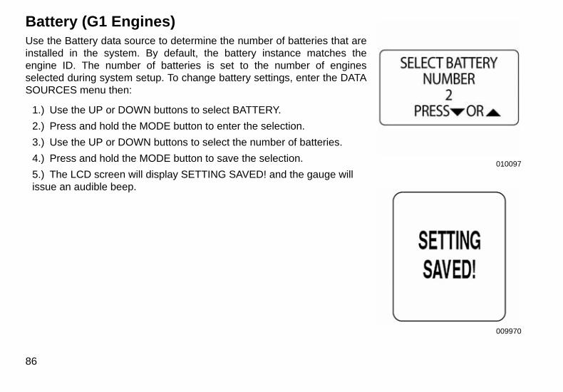
Battery (G1 Engines)Use the Battery data source to determine the number of batteries that areinstalled in the system. By default, the battery instance matches theengine ID. The number of batteries is set to the number of enginesselected during system setup. To change battery settings, enter the DATASOURCES menu then:
1.) Use the UP or DOWN buttons to select BATTERY.
2.) Press and hold the MODE button to enter the selection.
3.) Use the UP or DOWN buttons to select the number of batteries.
4.) Press and hold the MODE button to save the selection.
5.) The LCD screen will display SETTING SAVED! and the gauge will issue an audible beep.
86
010098
010099
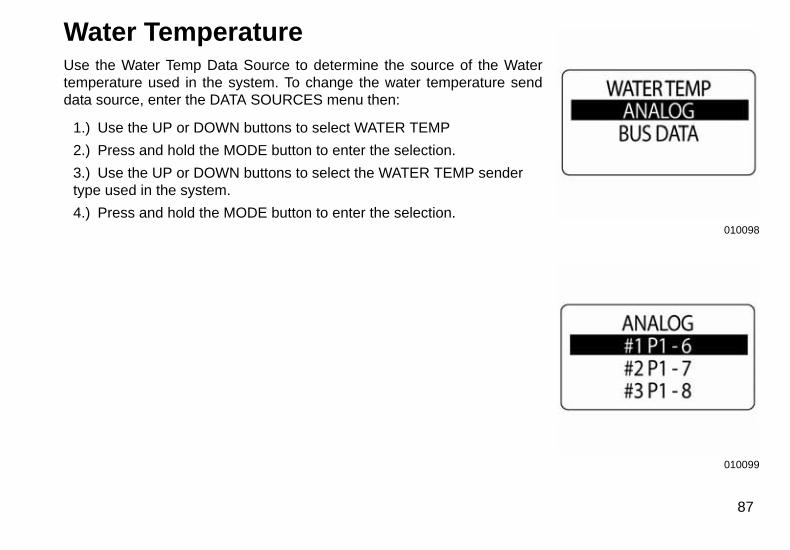
Water TemperatureUse the Water Temp Data Source to determine the source of the Watertemperature used in the system. To change the water temperature senddata source, enter the DATA SOURCES menu then:
1.) Use the UP or DOWN buttons to select WATER TEMP
2.) Press and hold the MODE button to enter the selection.
3.) Use the UP or DOWN buttons to select the WATER TEMP sender type used in the system.
4.) Press and hold the MODE button to enter the selection.
87
010100
010099
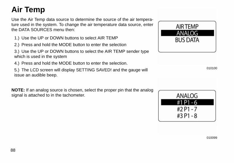
Air TempUse the Air Temp data source to determine the source of the air tempera-ture used in the system. To change the air temperature data source, enterthe DATA SOURCES menu then:
1.) Use the UP or DOWN buttons to select AIR TEMP
2.) Press and hold the MODE button to enter the selection
3.) Use the UP or DOWN buttons to select the AIR TEMP sender type which is used in the system
4.) Press and hold the MODE button to enter the selection.
5.) The LCD screen will display SETTING SAVED! and the gauge will issue an audible beep.
NOTE: If an analog source is chosen, select the proper pin that the analogsignal is attached to in the tachometer.
88
010101
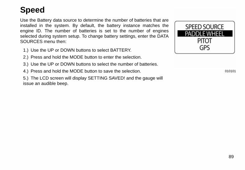
SpeedUse the Battery data source to determine the number of batteries that areinstalled in the system. By default, the battery instance matches theengine ID. The number of batteries is set to the number of enginesselected during system setup. To change battery settings, enter the DATASOURCES menu then:
1.) Use the UP or DOWN buttons to select BATTERY.
2.) Press and hold the MODE button to enter the selection.
3.) Use the UP or DOWN buttons to select the number of batteries.
4.) Press and hold the MODE button to save the selection.
5.) The LCD screen will display SETTING SAVED! and the gauge will issue an audible beep.
89
010102
010103
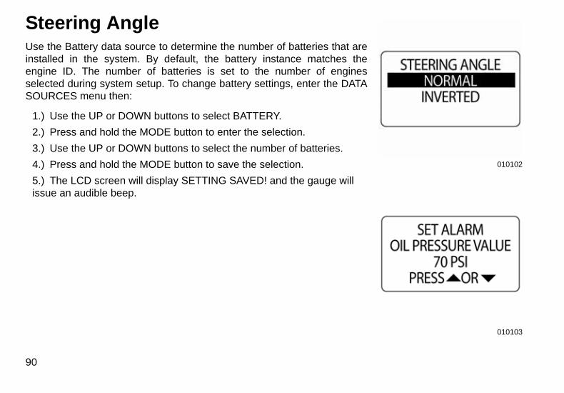
Steering AngleUse the Battery data source to determine the number of batteries that areinstalled in the system. By default, the battery instance matches theengine ID. The number of batteries is set to the number of enginesselected during system setup. To change battery settings, enter the DATASOURCES menu then:
1.) Use the UP or DOWN buttons to select BATTERY.
2.) Press and hold the MODE button to enter the selection.
3.) Use the UP or DOWN buttons to select the number of batteries.
4.) Press and hold the MODE button to save the selection.
5.) The LCD screen will display SETTING SAVED! and the gauge will issue an audible beep.
90
010104
010105
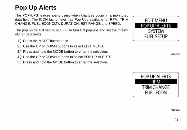
Pop Up AlertsThe POP-UPS feature alerts users when changes occur in a monitoreddata field. The ICON tachometer has Pop Ups available for RPM, TRIMCHANGE, FUEL ECONOMY, DURATION, EST RANGE and SPEED.
The pop up default setting is OFF. To turn ON pop ups and set the thresh-old for data fields:
1.) Press the MODE button once.
2.) Use the UP or DOWN buttons to select EDIT MENU.
3.) Press and hold the MODE button to enter the selection.
4.) Use the UP or DOWN buttons to select POP UP ALERTS.
5.) Press and hold the MODE button to enter the selection.
91
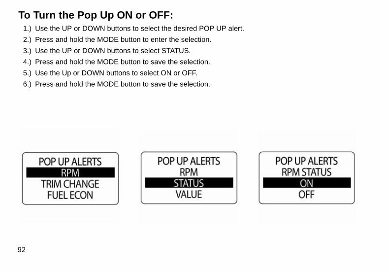
To Turn the Pop Up ON or OFF:1.) Use the UP or DOWN buttons to select the desired POP UP alert.
2.) Press and hold the MODE button to enter the selection.
3.) Use the UP or DOWN buttons to select STATUS.
4.) Press and hold the MODE button to save the selection.
5.) Use the Up or DOWN buttons to select ON or OFF.
6.) Press and hold the MODE button to save the selection.
92
010109
010110
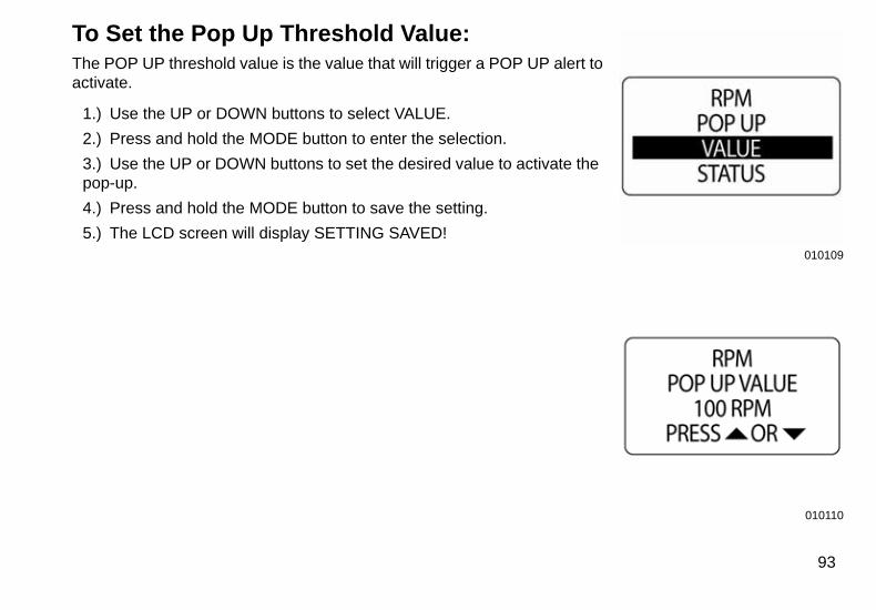
To Set the Pop Up Threshold Value:The POP UP threshold value is the value that will trigger a POP UP alert toactivate.
1.) Use the UP or DOWN buttons to select VALUE.
2.) Press and hold the MODE button to enter the selection.
3.) Use the UP or DOWN buttons to set the desired value to activate the pop-up.
4.) Press and hold the MODE button to save the setting.
5.) The LCD screen will display SETTING SAVED!
93
010111
010112
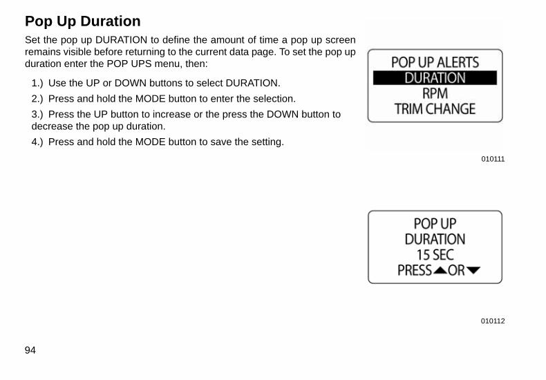
Pop Up DurationSet the pop up DURATION to define the amount of time a pop up screenremains visible before returning to the current data page. To set the pop upduration enter the POP UPS menu, then:
1.) Use the UP or DOWN buttons to select DURATION.
2.) Press and hold the MODE button to enter the selection.
3.) Press the UP button to increase or the press the DOWN button to decrease the pop up duration.
4.) Press and hold the MODE button to save the setting.
94
010113
010114
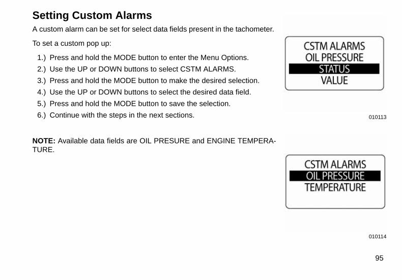
Setting Custom AlarmsA custom alarm can be set for select data fields present in the tachometer.
To set a custom pop up:
1.) Press and hold the MODE button to enter the Menu Options.
2.) Use the UP or DOWN buttons to select CSTM ALARMS.
3.) Press and hold the MODE button to make the desired selection.
4.) Use the UP or DOWN buttons to select the desired data field.
5.) Press and hold the MODE button to save the selection.
6.) Continue with the steps in the next sections.
NOTE: Available data fields are OIL PRESURE and ENGINE TEMPERA-TURE.
95
010115
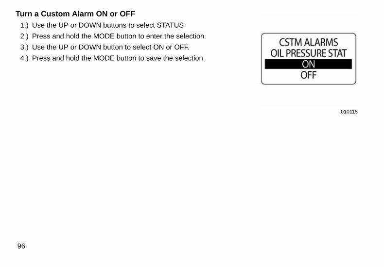
Turn a Custom Alarm ON or OFF
1.) Use the UP or DOWN buttons to select STATUS
2.) Press and hold the MODE button to enter the selection.
3.) Use the UP or DOWN button to select ON or OFF.
4.) Press and hold the MODE button to save the selection.
96
010116
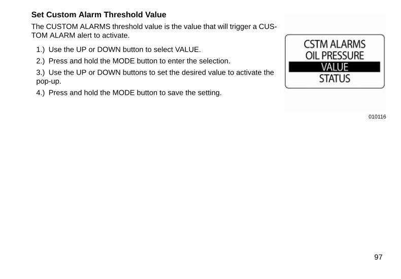
Set Custom Alarm Threshold Value
The CUSTOM ALARMS threshold value is the value that will trigger a CUS-TOM ALARM alert to activate.
1.) Use the UP or DOWN button to select VALUE.
2.) Press and hold the MODE button to enter the selection.
3.) Use the UP or DOWN buttons to set the desired value to activate the pop-up.
4.) Press and hold the MODE button to save the setting.
97
010117
010118
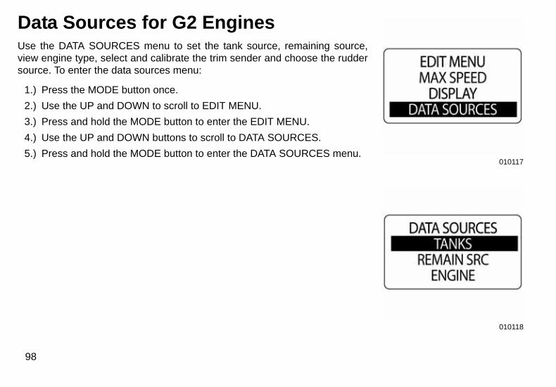
Data Sources for G2 EnginesUse the DATA SOURCES menu to set the tank source, remaining source,view engine type, select and calibrate the trim sender and choose the ruddersource. To enter the data sources menu:
1.) Press the MODE button once.
2.) Use the UP and DOWN to scroll to EDIT MENU.
3.) Press and hold the MODE button to enter the EDIT MENU.
4.) Use the UP and DOWN buttons to scroll to DATA SOURCES.
5.) Press and hold the MODE button to enter the DATA SOURCES menu.
98
010119
010120
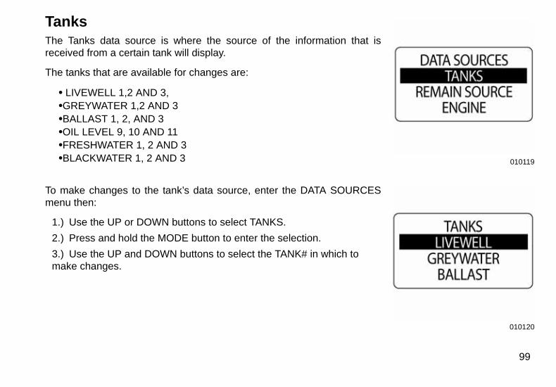
TanksThe Tanks data source is where the source of the information that isreceived from a certain tank will display.
The tanks that are available for changes are:
• LIVEWELL 1,2 AND 3,•GREYWATER 1,2 AND 3•BALLAST 1, 2, AND 3•OIL LEVEL 9, 10 AND 11•FRESHWATER 1, 2 AND 3•BLACKWATER 1, 2 AND 3
To make changes to the tank’s data source, enter the DATA SOURCESmenu then:
1.) Use the UP or DOWN buttons to select TANKS.
2.) Press and hold the MODE button to enter the selection.
3.) Use the UP and DOWN buttons to select the TANK# in which to make changes.
99
010121
010122
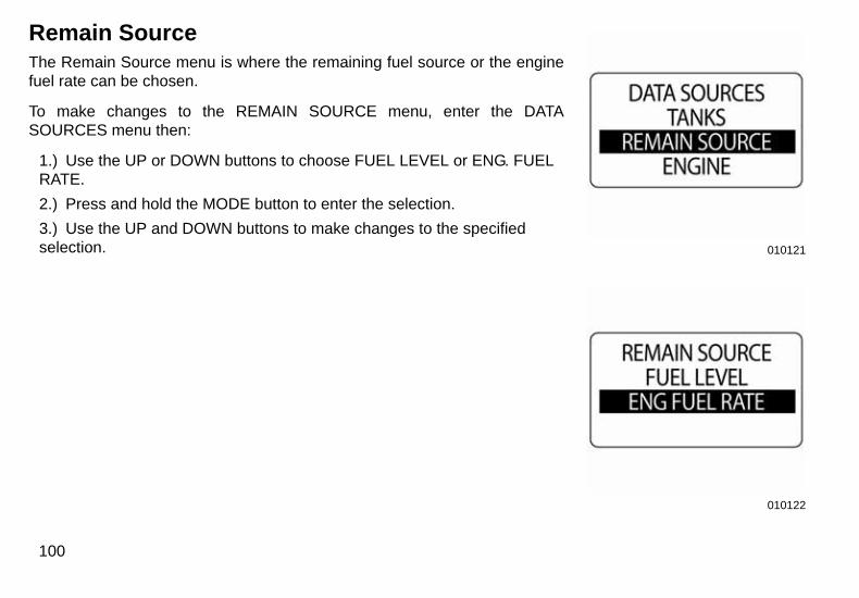
Remain SourceThe Remain Source menu is where the remaining fuel source or the enginefuel rate can be chosen.
To make changes to the REMAIN SOURCE menu, enter the DATASOURCES menu then:
1.) Use the UP or DOWN buttons to choose FUEL LEVEL or ENG. FUEL RATE.
2.) Press and hold the MODE button to enter the selection.
3.) Use the UP and DOWN buttons to make changes to the specified selection.
100
010123
010124
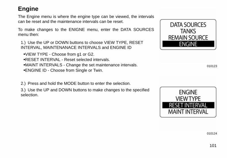
EngineThe Engine menu is where the engine type can be viewed, the intervalscan be reset and the maintenance intervals can be reset.
To make changes to the ENIGNE menu, enter the DATA SOURCESmenu then:
1.) Use the UP or DOWN buttons to choose VIEW TYPE, RESET INTERVAL, MAINTENANACE INTERVALS and ENGINE ID
•VIEW TYPE - Choose from g1 or G2.•RESET INTERVAL - Reset selected intervals.•MAINT INTERVALS - Change the set maintenance intervals.•ENGINE ID - Choose from Single or Twin.
2.) Press and hold the MODE button to enter the selection.
3.) Use the UP and DOWN buttons to make changes to the specified selection.
101
010125
010126
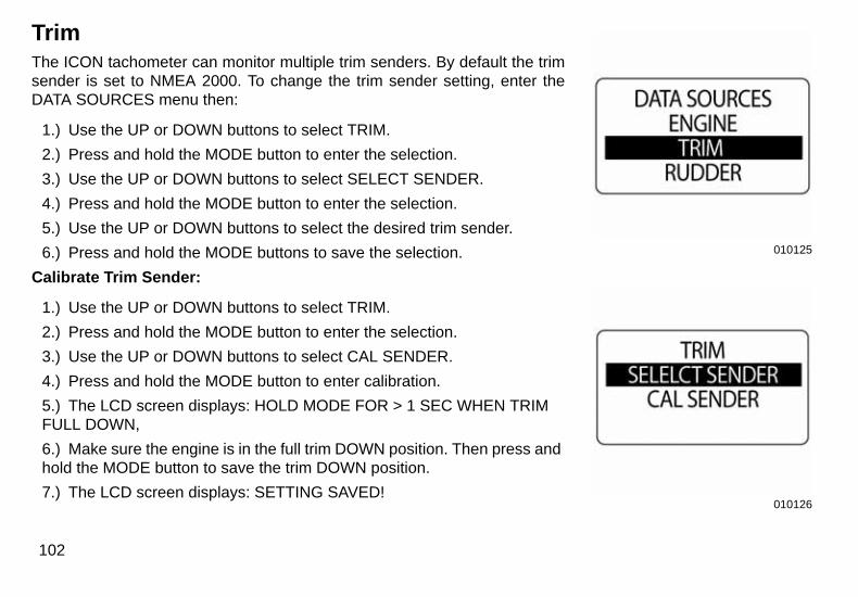
TrimThe ICON tachometer can monitor multiple trim senders. By default the trimsender is set to NMEA 2000. To change the trim sender setting, enter theDATA SOURCES menu then:
1.) Use the UP or DOWN buttons to select TRIM.
2.) Press and hold the MODE button to enter the selection.
3.) Use the UP or DOWN buttons to select SELECT SENDER.
4.) Press and hold the MODE button to enter the selection.
5.) Use the UP or DOWN buttons to select the desired trim sender.
6.) Press and hold the MODE buttons to save the selection.
Calibrate Trim Sender:
1.) Use the UP or DOWN buttons to select TRIM.
2.) Press and hold the MODE button to enter the selection.
3.) Use the UP or DOWN buttons to select CAL SENDER.
4.) Press and hold the MODE button to enter calibration.
5.) The LCD screen displays: HOLD MODE FOR > 1 SEC WHEN TRIM FULL DOWN,
6.) Make sure the engine is in the full trim DOWN position. Then press and hold the MODE button to save the trim DOWN position.
7.) The LCD screen displays: SETTING SAVED!
102
010127
010099
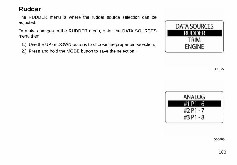
RudderThe RUDDER menu is where the rudder source selection can beadjusted.
To make changes to the RUDDER menu, enter the DATA SOURCESmenu then:
1.) Use the UP or DOWN buttons to choose the proper pin selection.
2.) Press and hold the MODE button to save the selection.
103
010128
010129
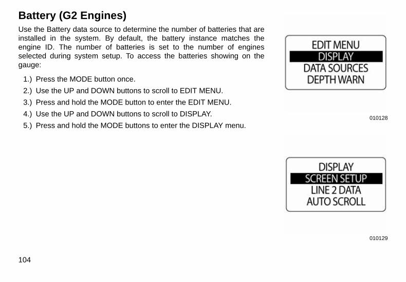
Battery (G2 Engines)Use the Battery data source to determine the number of batteries that areinstalled in the system. By default, the battery instance matches theengine ID. The number of batteries is set to the number of enginesselected during system setup. To access the batteries showing on thegauge:
1.) Press the MODE button once.
2.) Use the UP and DOWN buttons to scroll to EDIT MENU.
3.) Press and hold the MODE button to enter the EDIT MENU.
4.) Use the UP and DOWN buttons to scroll to DISPLAY.
5.) Press and hold the MODE buttons to enter the DISPLAY menu.
104
010130
010131
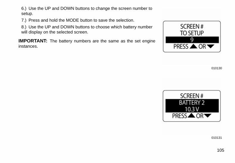
6.) Use the UP and DOWN buttons to change the screen number to setup.
7.) Press and hold the MODE button to save the selection.
8.) Use the UP and DOWN buttons to choose which battery number will display on the selected screen.
IMPORTANT: The battery numbers are the same as the set engineinstances.
105
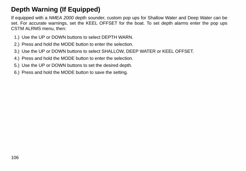
Depth Warning (If Equipped)If equipped with a NMEA 2000 depth sounder, custom pop ups for Shallow Water and Deep Water can beset. For accurate warnings, set the KEEL OFFSET for the boat. To set depth alarms enter the pop upsCSTM ALRMS menu, then:
1.) Use the UP or DOWN buttons to select DEPTH WARN.
2.) Press and hold the MODE button to enter the selection.
3.) Use the UP or DOWN buttons to select SHALLOW, DEEP WATER or KEEL OFFSET.
4.) Press and hold the MODE button to enter the selection.
5.) Use the UP or DOWN buttons to set the desired depth.
6.) Press and hold the MODE button to save the setting.
106

Speedometer Operation
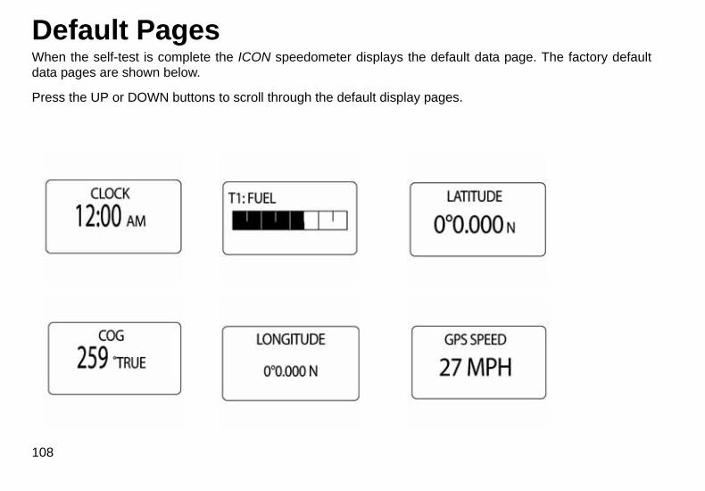
Default PagesWhen the self-test is complete the ICON speedometer displays the default data page. The factory defaultdata pages are shown below.
Press the UP or DOWN buttons to scroll through the default display pages.
108
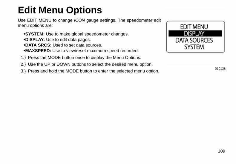
Edit Menu OptionsUse EDIT MENU to change ICON gauge settings. The speedometer editmenu options are:
•SYSTEM: Use to make global speedometer changes.•DISPLAY: Use to edit data pages.•DATA SRCS: Used to set data sources.•MAXSPEED: Use to view/reset maximum speed recorded.
1.) Press the MODE button once to display the Menu Options.
2.) Use the UP or DOWN buttons to select the desired menu option.
3.) Press and hold the MODE button to enter the selected menu option.
010138109
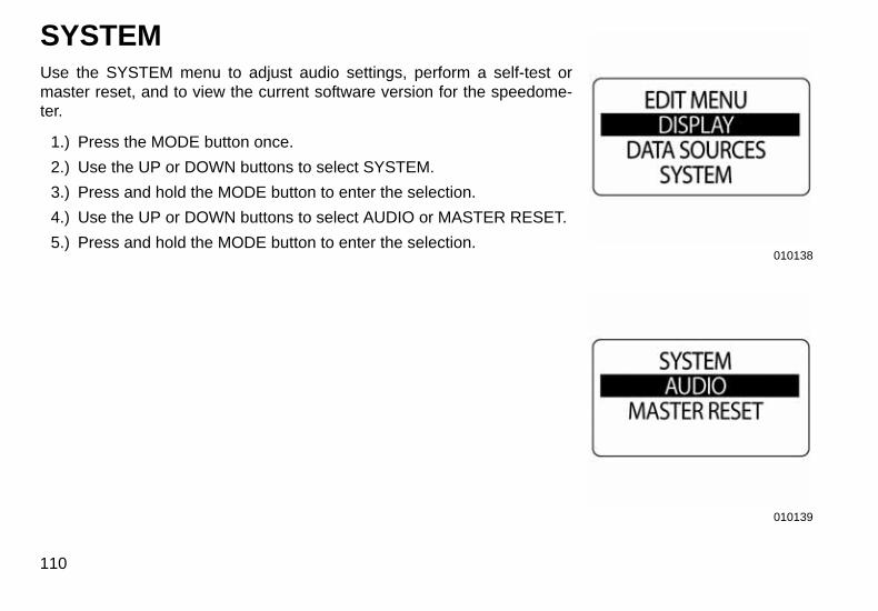
SYSTEMUse the SYSTEM menu to adjust audio settings, perform a self-test ormaster reset, and to view the current software version for the speedome-ter.
1.) Press the MODE button once.
2.) Use the UP or DOWN buttons to select SYSTEM.
3.) Press and hold the MODE button to enter the selection.
4.) Use the UP or DOWN buttons to select AUDIO or MASTER RESET.
5.) Press and hold the MODE button to enter the selection.
110
010138
010139
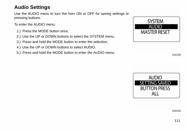
Audio SettingsUse the AUDIO menu to turn the horn ON or OFF for saving settings orpressing buttons.
To enter the AUDIO menu:
1.) Press the MODE button once.
2.) Use the UP or DOWN buttons to select the SYSTEM menu.
3.) Press and hold the MODE button to enter the selection.
4.) Use the UP or DOWN buttons to select AUDIO.
5.) Press and hold the MODE button to enter the AUDIO menu.
010139010140
111

Setting SavedUse SETTING SAVED to turn the horn ON or OFF after a setting is savedin the ICON speedometer. To change the setting enter the AUDIO menu,then:
1.) Use the UP or DOWN buttons to select SETTING SAVED.
2.) Press and hold the MODE button to enter the selection.
3.) Use the UP or DOWN buttons to select ON or OFF.
4.) Press and hold the MODE button to save the setting. The gauge will display SETTING SAVED!
112
010025
009970

Button PressUse BTN PRESS to turn the horn ON or OFF when a button is pressed onthe speedometer. To change the setting enter the AUDIO menu, then:
1.) Use the UP or DOWN buttons to select BUTTON PRESS.
2.) Press and hold the MODE button to enter BUTTON PRESS.
3.) Use the UP or DOWN buttons to select ON or OFF.
4.) Press and hold the MODE button to save the setting. The gauge will display SETTING SAVED!
010141
010142
113
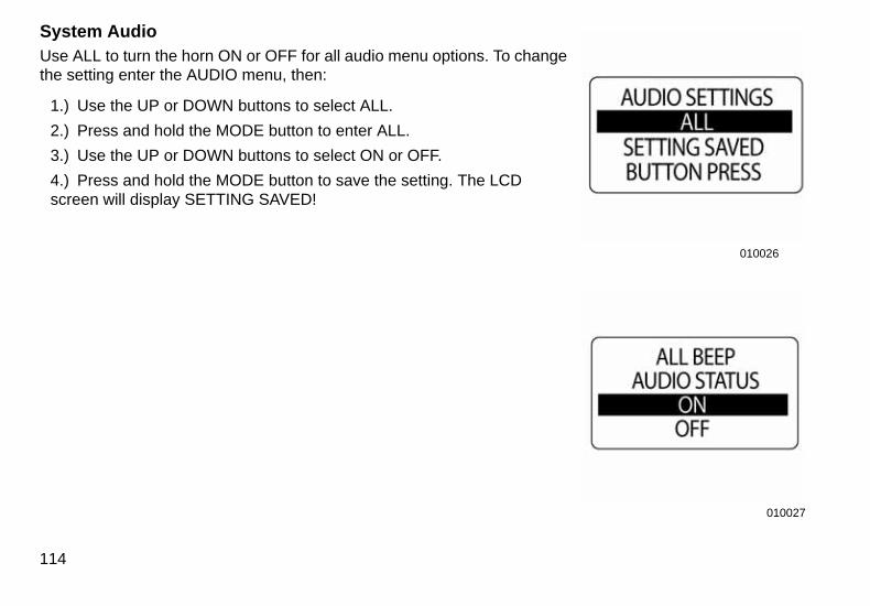
System AudioUse ALL to turn the horn ON or OFF for all audio menu options. To changethe setting enter the AUDIO menu, then:
1.) Use the UP or DOWN buttons to select ALL.
2.) Press and hold the MODE button to enter ALL.
3.) Use the UP or DOWN buttons to select ON or OFF.
4.) Press and hold the MODE button to save the setting. The LCD screen will display SETTING SAVED!
114
010026
010027
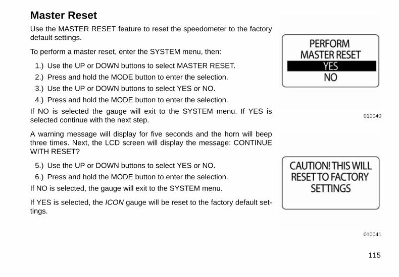
Master ResetUse the MASTER RESET feature to reset the speedometer to the factorydefault settings.
To perform a master reset, enter the SYSTEM menu, then:
1.) Use the UP or DOWN buttons to select MASTER RESET.
2.) Press and hold the MODE button to enter the selection.
3.) Use the UP or DOWN buttons to select YES or NO.
4.) Press and hold the MODE button to enter the selection.
If NO is selected the gauge will exit to the SYSTEM menu. If YES isselected continue with the next step.
A warning message will display for five seconds and the horn will beepthree times. Next, the LCD screen will display the message: CONTINUEWITH RESET?
5.) Use the UP or DOWN buttons to select YES or NO.
6.) Press and hold the MODE button to enter the selection.
If NO is selected, the gauge will exit to the SYSTEM menu.
If YES is selected, the ICON gauge will be reset to the factory default set-tings.
010040
010041
115
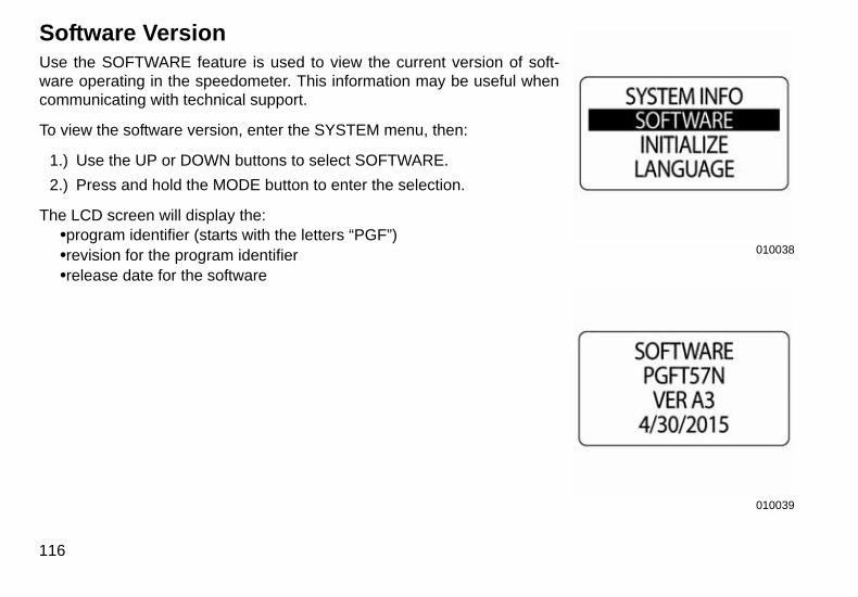
Software VersionUse the SOFTWARE feature is used to view the current version of soft-ware operating in the speedometer. This information may be useful whencommunicating with technical support.
To view the software version, enter the SYSTEM menu, then:
1.) Use the UP or DOWN buttons to select SOFTWARE.
2.) Press and hold the MODE button to enter the selection.
The LCD screen will display the:•program identifier (starts with the letters “PGF”)•revision for the program identifier•release date for the software
116
010038
010039
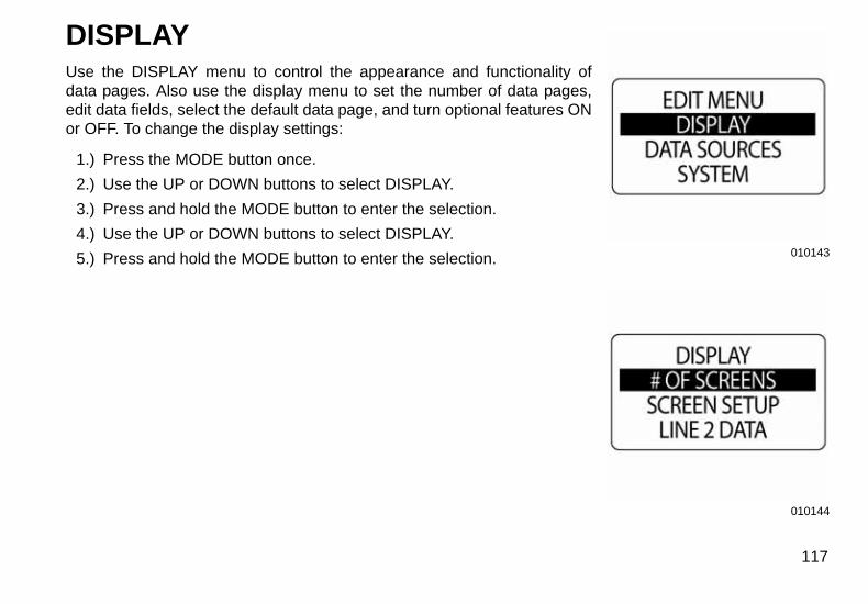
DISPLAYUse the DISPLAY menu to control the appearance and functionality ofdata pages. Also use the display menu to set the number of data pages,edit data fields, select the default data page, and turn optional features ONor OFF. To change the display settings:
1.) Press the MODE button once.
2.) Use the UP or DOWN buttons to select DISPLAY.
3.) Press and hold the MODE button to enter the selection.
4.) Use the UP or DOWN buttons to select DISPLAY.
5.) Press and hold the MODE button to enter the selection.
010143010144
117
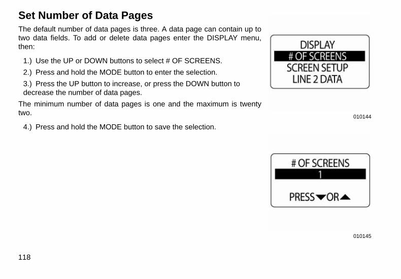
Set Number of Data PagesThe default number of data pages is three. A data page can contain up totwo data fields. To add or delete data pages enter the DISPLAY menu,then:
1.) Use the UP or DOWN buttons to select # OF SCREENS.
2.) Press and hold the MODE button to enter the selection.
3.) Press the UP button to increase, or press the DOWN button to decrease the number of data pages.
The minimum number of data pages is one and the maximum is twentytwo.
4.) Press and hold the MODE button to save the selection.
118
010144
010145
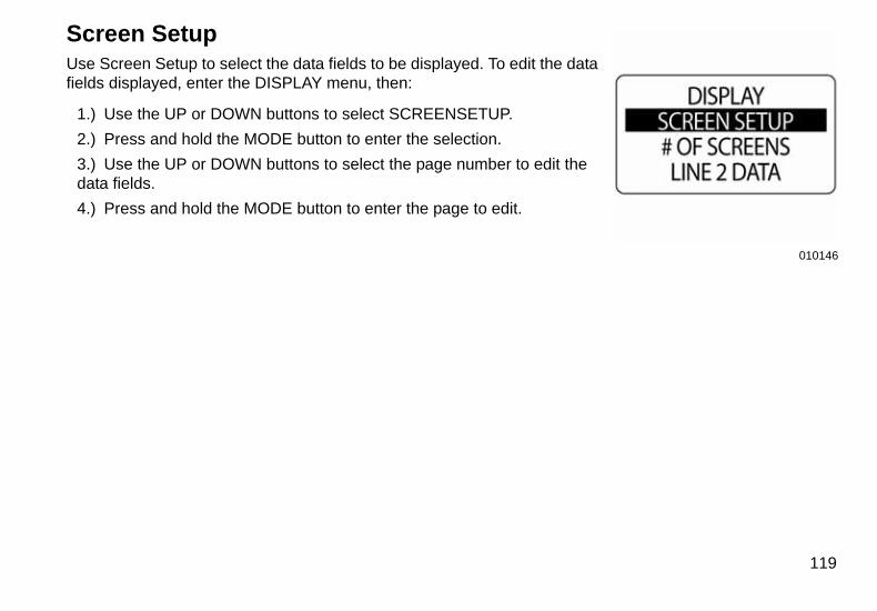
Screen SetupUse Screen Setup to select the data fields to be displayed. To edit the datafields displayed, enter the DISPLAY menu, then:
1.) Use the UP or DOWN buttons to select SCREENSETUP.
2.) Press and hold the MODE button to enter the selection.
3.) Use the UP or DOWN buttons to select the page number to edit the data fields.
4.) Press and hold the MODE button to enter the page to edit.
010146
119
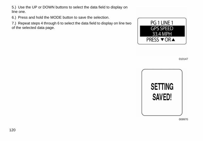
5.) Use the UP or DOWN buttons to select the data field to display on line one.
6.) Press and hold the MODE button to save the selection.
7.) Repeat steps 4 through 6 to select the data field to display on line two of the selected data page.
120
010147
009970
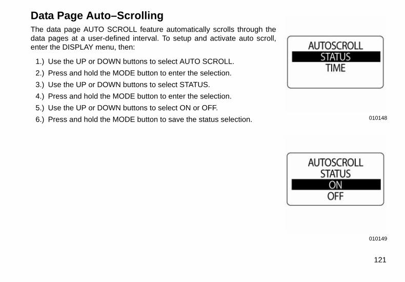
Data Page Auto–ScrollingThe data page AUTO SCROLL feature automatically scrolls through thedata pages at a user-defined interval. To setup and activate auto scroll,enter the DISPLAY menu, then:
1.) Use the UP or DOWN buttons to select AUTO SCROLL.
2.) Press and hold the MODE button to enter the selection.
3.) Use the UP or DOWN buttons to select STATUS.
4.) Press and hold the MODE button to enter the selection.
5.) Use the UP or DOWN buttons to select ON or OFF.
6.) Press and hold the MODE button to save the status selection.
010148010149
121
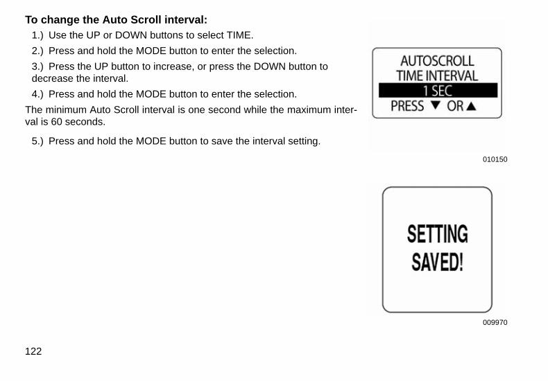
To change the Auto Scroll interval:1.) Use the UP or DOWN buttons to select TIME.
2.) Press and hold the MODE button to enter the selection.
3.) Press the UP button to increase, or press the DOWN button to decrease the interval.
4.) Press and hold the MODE button to enter the selection.
The minimum Auto Scroll interval is one second while the maximum inter-val is 60 seconds.
5.) Press and hold the MODE button to save the interval setting.
122
010150
009970
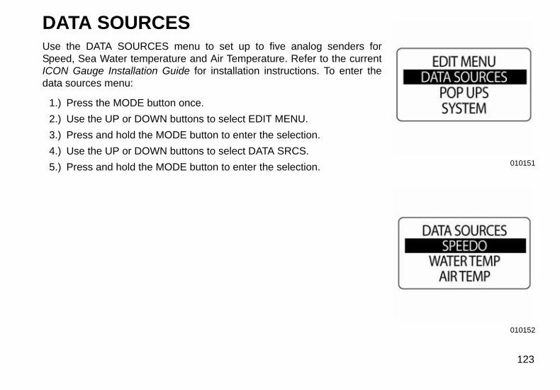
DATA SOURCESUse the DATA SOURCES menu to set up to five analog senders forSpeed, Sea Water temperature and Air Temperature. Refer to the currentICON Gauge Installation Guide for installation instructions. To enter thedata sources menu:
1.) Press the MODE button once.
2.) Use the UP or DOWN buttons to select EDIT MENU.
3.) Press and hold the MODE button to enter the selection.
4.) Use the UP or DOWN buttons to select DATA SRCS.
5.) Press and hold the MODE button to enter the selection.
010151010152
123
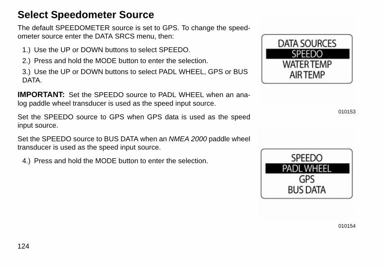
Select Speedometer SourceThe default SPEEDOMETER source is set to GPS. To change the speed-ometer source enter the DATA SRCS menu, then:
1.) Use the UP or DOWN buttons to select SPEEDO.
2.) Press and hold the MODE button to enter the selection.
3.) Use the UP or DOWN buttons to select PADL WHEEL, GPS or BUS DATA.
IMPORTANT: Set the SPEEDO source to PADL WHEEL when an ana-log paddle wheel transducer is used as the speed input source.
Set the SPEEDO source to GPS when GPS data is used as the speedinput source.
Set the SPEEDO source to BUS DATA when an NMEA 2000 paddle wheeltransducer is used as the speed input source.
4.) Press and hold the MODE button to enter the selection.
124
010153
010154
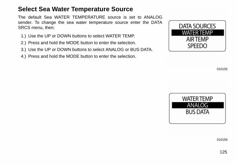
Select Sea Water Temperature SourceThe default Sea WATER TEMPERATURE source is set to ANALOGsender. To change the sea water temperature source enter the DATASRCS menu, then:
1.) Use the UP or DOWN buttons to select WATER TEMP.
2.) Press and hold the MODE button to enter the selection.
3.) Use the UP or DOWN buttons to select ANALOG or BUS DATA.
4.) Press and hold the MODE button to enter the selection.
010155
010156
125
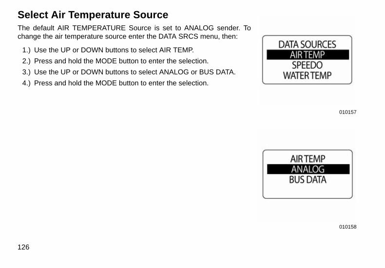
Select Air Temperature SourceThe default AIR TEMPERATURE Source is set to ANALOG sender. Tochange the air temperature source enter the DATA SRCS menu, then:
1.) Use the UP or DOWN buttons to select AIR TEMP.
2.) Press and hold the MODE button to enter the selection.
3.) Use the UP or DOWN buttons to select ANALOG or BUS DATA.
4.) Press and hold the MODE button to enter the selection.
126
010157
010158
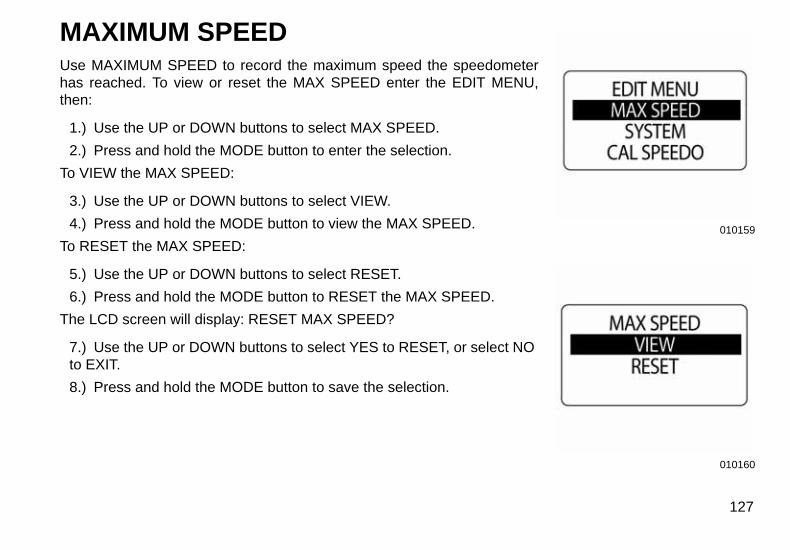
MAXIMUM SPEEDUse MAXIMUM SPEED to record the maximum speed the speedometerhas reached. To view or reset the MAX SPEED enter the EDIT MENU,then:
1.) Use the UP or DOWN buttons to select MAX SPEED.
2.) Press and hold the MODE button to enter the selection.
To VIEW the MAX SPEED:
3.) Use the UP or DOWN buttons to select VIEW.
4.) Press and hold the MODE button to view the MAX SPEED.
To RESET the MAX SPEED:
5.) Use the UP or DOWN buttons to select RESET.
6.) Press and hold the MODE button to RESET the MAX SPEED.
The LCD screen will display: RESET MAX SPEED?
7.) Use the UP or DOWN buttons to select YES to RESET, or select NO to EXIT.
8.) Press and hold the MODE button to save the selection.
010159
010160
127

128

Troubleshooting
Troubleshooting StepsUse a process of elimination to troubleshoot network problems.
1. If the LCD screen of the ICON gauge displays a value of zero (0) in any data field, it indicates the gauge isnot receiving a signal from one or more devices.
• Make sure the data sources are configured.• If multiple data fields are displaying “0”, check common items such as cables and t-connectors.• Remove components from the network one at a time to isolate failed components.• Look for damaged parts.• Check connectors for corrosion.• Swap known good components (sensor, cables or t-connectors) to isolate the faulty component.• Reconnect the good component to the network and the remove the next one in line.• Continue this process for each device, cable or tee connector on the network until the faulty part is found.
NOTE: After a component is reconnected to the network, cycle the key switch OFF and back ON to reset thegauge(s).
130
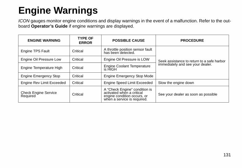
Engine WarningsICON gauges monitor engine conditions and display warnings in the event of a malfunction. Refer to the out-board Operator’s Guide if engine warnings are displayed.
ENGINE WARNINGTYPE OF ERROR
POSSIBLE CAUSE PROCEDURE
Engine TPS Fault Critical A throttle position sensor fault has been detected.
Seek assistance to return to a safe harbor immediately and see your dealer.
Engine Oil Pressure Low Critical Engine Oil Pressure is LOW
Engine Temperature High Critical Engine Coolant Temperature is HIGH
Engine Emergency Stop Critical Engine Emergency Stop Mode
Engine Rev Limit Exceeded Critical Engine Speed Limit Exceeded Slow the engine down
Check Engine Service Required Critical
A “Check Engine” condition is activated when a critical engine condition occurs, or when a service is required.
See your dealer as soon as possible
131
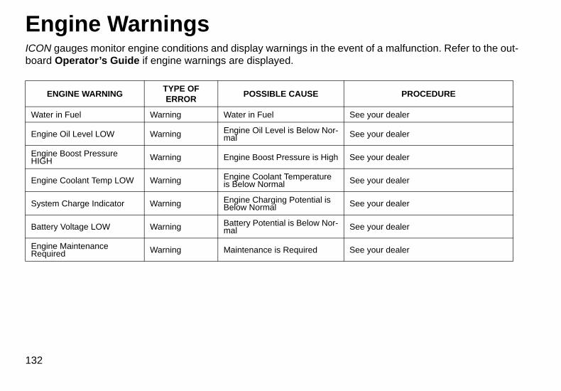
Engine WarningsICON gauges monitor engine conditions and display warnings in the event of a malfunction. Refer to the out-board Operator’s Guide if engine warnings are displayed.
ENGINE WARNINGTYPE OF ERROR
POSSIBLE CAUSE PROCEDURE
Water in Fuel Warning Water in Fuel See your dealer
Engine Oil Level LOW Warning Engine Oil Level is Below Nor-mal See your dealer
Engine Boost Pressure HIGH Warning Engine Boost Pressure is High See your dealer
Engine Coolant Temp LOW Warning Engine Coolant Temperature is Below Normal See your dealer
System Charge Indicator Warning Engine Charging Potential is Below Normal See your dealer
Battery Voltage LOW Warning Battery Potential is Below Nor-mal See your dealer
Engine Maintenance Required Warning Maintenance is Required See your dealer
132
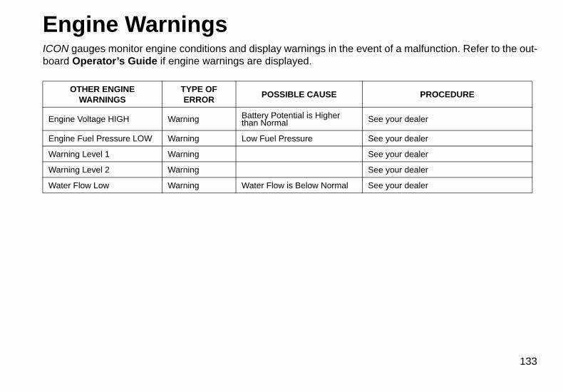
Engine WarningsICON gauges monitor engine conditions and display warnings in the event of a malfunction. Refer to the out-board Operator’s Guide if engine warnings are displayed.
OTHER ENGINEWARNINGS
TYPE OF ERROR
POSSIBLE CAUSE PROCEDURE
Engine Voltage HIGH Warning Battery Potential is Higher than Normal See your dealer
Engine Fuel Pressure LOW Warning Low Fuel Pressure See your dealer
Warning Level 1 Warning See your dealer
Warning Level 2 Warning See your dealer
Water Flow Low Warning Water Flow is Below Normal See your dealer
133
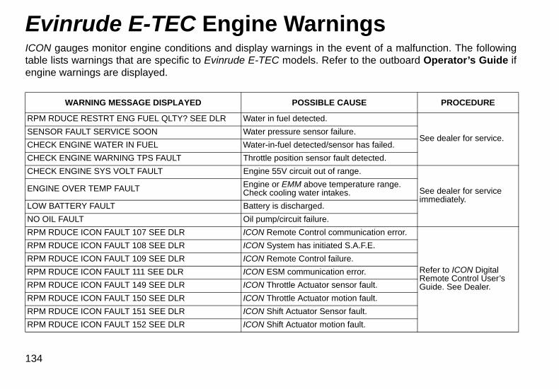
Evinrude E-TEC Engine WarningsICON gauges monitor engine conditions and display warnings in the event of a malfunction. The followingtable lists warnings that are specific to Evinrude E-TEC models. Refer to the outboard Operator’s Guide ifengine warnings are displayed.
WARNING MESSAGE DISPLAYED POSSIBLE CAUSE PROCEDURE
RPM RDUCE RESTRT ENG FUEL QLTY? SEE DLR Water in fuel detected.
See dealer for service.SENSOR FAULT SERVICE SOON Water pressure sensor failure.
CHECK ENGINE WATER IN FUEL Water-in-fuel detected/sensor has failed.
CHECK ENGINE WARNING TPS FAULT Throttle position sensor fault detected.
CHECK ENGINE SYS VOLT FAULT Engine 55V circuit out of range.
See dealer for service immediately.
ENGINE OVER TEMP FAULT Engine or EMM above temperature range. Check cooling water intakes.
LOW BATTERY FAULT Battery is discharged.
NO OIL FAULT Oil pump/circuit failure.
RPM RDUCE ICON FAULT 107 SEE DLR ICON Remote Control communication error.
Refer to ICON Digital Remote Control User’s Guide. See Dealer.
RPM RDUCE ICON FAULT 108 SEE DLR ICON System has initiated S.A.F.E.
RPM RDUCE ICON FAULT 109 SEE DLR ICON Remote Control failure.
RPM RDUCE ICON FAULT 111 SEE DLR ICON ESM communication error.
RPM RDUCE ICON FAULT 149 SEE DLR ICON Throttle Actuator sensor fault.
RPM RDUCE ICON FAULT 150 SEE DLR ICON Throttle Actuator motion fault.
RPM RDUCE ICON FAULT 151 SEE DLR ICON Shift Actuator Sensor fault.
RPM RDUCE ICON FAULT 152 SEE DLR ICON Shift Actuator motion fault.
134
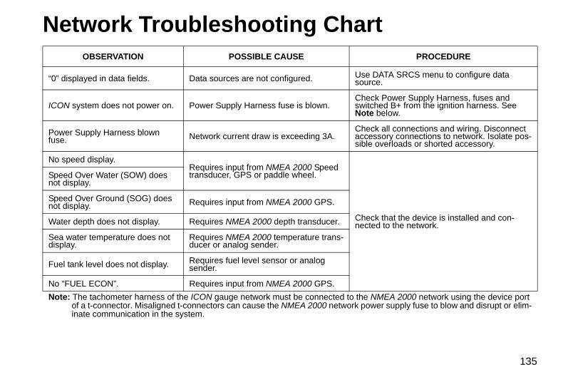
Network Troubleshooting ChartOBSERVATION POSSIBLE CAUSE PROCEDURE
“0” displayed in data fields. Data sources are not configured. Use DATA SRCS menu to configure data source.
ICON system does not power on. Power Supply Harness fuse is blown.Check Power Supply Harness, fuses and switched B+ from the ignition harness. See Note below.
Power Supply Harness blown fuse. Network current draw is exceeding 3A.
Check all connections and wiring. Disconnect accessory connections to network. Isolate pos-sible overloads or shorted accessory.
No speed display.Requires input from NMEA 2000 Speed transducer, GPS or paddle wheel.
Check that the device is installed and con-nected to the network.
Speed Over Water (SOW) does not display.
Speed Over Ground (SOG) does not display. Requires input from NMEA 2000 GPS.
Water depth does not display. Requires NMEA 2000 depth transducer.
Sea water temperature does not display.
Requires NMEA 2000 temperature trans-ducer or analog sender.
Fuel tank level does not display. Requires fuel level sensor or analog sender.
No “FUEL ECON”. Requires input from NMEA 2000 GPS.
Note: The tachometer harness of the ICON gauge network must be connected to the NMEA 2000 network using the device port of a t-connector. Misaligned t-connectors can cause the NMEA 2000 network power supply fuse to blow and disrupt or elim-inate communication in the system.
135
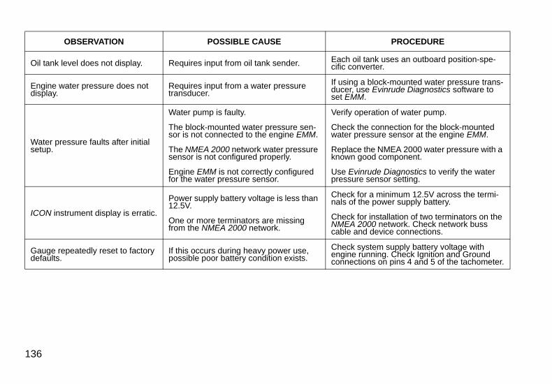
OBSERVATION POSSIBLE CAUSE PROCEDURE
Oil tank level does not display. Requires input from oil tank sender. Each oil tank uses an outboard position-spe-cific converter.
Engine water pressure does not display.
Requires input from a water pressure transducer.
If using a block-mounted water pressure trans-ducer, use Evinrude Diagnostics software to set EMM.
Water pressure faults after initial setup.
Water pump is faulty.
The block-mounted water pressure sen-sor is not connected to the engine EMM.
The NMEA 2000 network water pressure sensor is not configured properly.
Engine EMM is not correctly configured for the water pressure sensor.
Verify operation of water pump.
Check the connection for the block-mounted water pressure sensor at the engine EMM.
Replace the NMEA 2000 water pressure with a known good component.
Use Evinrude Diagnostics to verify the water pressure sensor setting.
ICON instrument display is erratic.
Power supply battery voltage is less than 12.5V.
One or more terminators are missing from the NMEA 2000 network.
Check for a minimum 12.5V across the termi-nals of the power supply battery.
Check for installation of two terminators on the NMEA 2000 network. Check network buss cable and device connections.
Gauge repeatedly reset to factory defaults.
If this occurs during heavy power use, possible poor battery condition exists.
Check system supply battery voltage with engine running. Check Ignition and Ground connections on pins 4 and 5 of the tachometer.
136

Reference
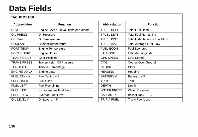
Data FieldsTACHOMETER
Abbreviation Function Abbreviation Function
RPM Engine Speed, Revolutions per Minute TFUEL USED Total Fuel Used
OIL PRESS Oil Pressure TFUEL LEFT Total Fuel Remaining
OIL Temp Oil Temperature TFUEL INST Total Instantaneous Fuel Flow
COOLANT Coolant Temperature TFUEL AVG Total Average Fuel Flow
PORT TEMP Engine Temperature FUEL ECON Fuel Economy
PORT HOURS Engine Hours LAT/LONG Latitude/Longitude
TRANS GEAR Gear Position GPS SPEED GPS Speed
TRANS PRESS Transmission Oil Pressure COG Course Over Ground
THROTTLE Throttle Percentage CLOCK Clock
ENGINE LOAD Engine Load HEADING Heading
FUEL TANK # Fuel Tank 1 – 5 BATTERY # Battery 1 – 5
FUEL USED Fuel Used TRIM Trim
FUEL LEFT Fuel Remaining DEPTH Depth
FUEL INST Instantaneous Fuel Flow WATER PRESS Water Pressure
FUEL FLOW Average Fuel Flow BALLAST # Ballast Tank 1 – 5
OIL LEVEL # Oil Level 1 – 5 TRIP A FUEL Trip A Fuel Used
138
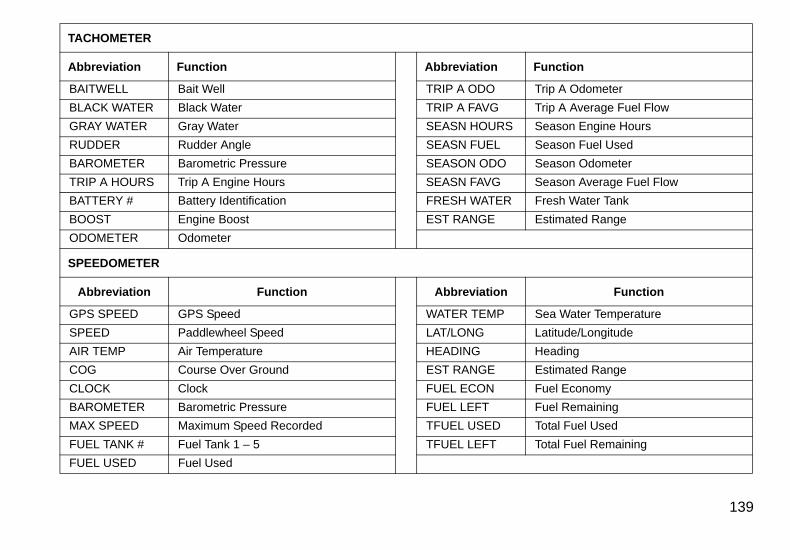
TACHOMETER
Abbreviation Function Abbreviation Function
BAITWELL Bait Well TRIP A ODO Trip A Odometer
BLACK WATER Black Water TRIP A FAVG Trip A Average Fuel Flow
GRAY WATER Gray Water SEASN HOURS Season Engine Hours
RUDDER Rudder Angle SEASN FUEL Season Fuel Used
BAROMETER Barometric Pressure SEASON ODO Season Odometer
TRIP A HOURS Trip A Engine Hours SEASN FAVG Season Average Fuel Flow
BATTERY # Battery Identification FRESH WATER Fresh Water Tank
BOOST Engine Boost EST RANGE Estimated Range
ODOMETER Odometer
SPEEDOMETER
Abbreviation Function Abbreviation Function
GPS SPEED GPS Speed WATER TEMP Sea Water Temperature
SPEED Paddlewheel Speed LAT/LONG Latitude/Longitude
AIR TEMP Air Temperature HEADING Heading
COG Course Over Ground EST RANGE Estimated Range
CLOCK Clock FUEL ECON Fuel Economy
BAROMETER Barometric Pressure FUEL LEFT Fuel Remaining
MAX SPEED Maximum Speed Recorded TFUEL USED Total Fuel Used
FUEL TANK # Fuel Tank 1 – 5 TFUEL LEFT Total Fuel Remaining
FUEL USED Fuel Used
139
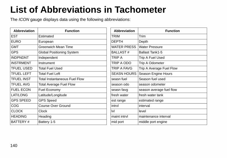
List of Abbreviations in TachometerThe ICON gauge displays data using the following abbreviations:
Abbreviation Function Abbreviation Function
EST Estimated TRIM Trim
EURO European DEPTH Depth
GMT Greenwich Mean Time WATER PRESS Water Pressure
GPS Global Positioning System BALLAST # Ballast Tank1-5
INDPNDNT Independent TRIP A Trip A Fuel Used
INSTRMENT Instrument TRIP A ODO Trip A Odometer
TFUEL USED Total Fuel Used TRIP A FAVG Trip A Average Fuel Flow
TFUEL LEFT Total Fuel Left SEASN HOURS Season Engine Hours
TFUEL INST Total Instantaneous Fuel Flow seasn fuel Season fuel used
TFUEL AVG Total Average Fuel Flow season odo season odometer
FUEL ECON Fuel Economy seasn favg season average fuel flow
LAT/LONG Latitude/Longitude fresh water fresh water tank
GPS SPEED GPS Speed est range estimated range
COG Course Over Ground intrvl interval
CLOCK Clock lvl level
HEADING Heading maint intrvl maintenance interval
BATTERY # Battery 1-5 mid port middle port engine
140
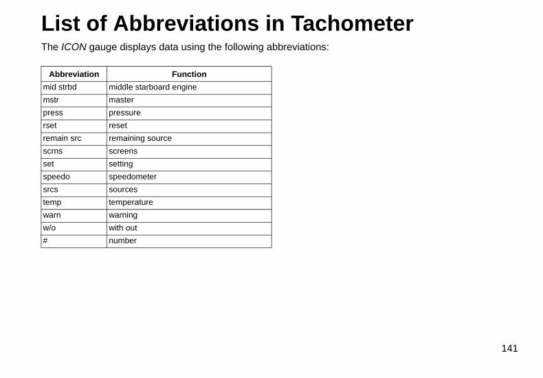
List of Abbreviations in TachometerThe ICON gauge displays data using the following abbreviations:
Abbreviation Function
mid strbd middle starboard engine
mstr master
press pressure
rset reset
remain src remaining source
scrns screens
set setting
speedo speedometer
srcs sources
temp temperature
warn warning
w/o with out
# number
141
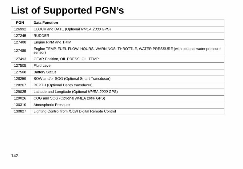
List of Supported PGN’sPGN Data Function
126992 CLOCK and DATE (Optional NMEA 2000 GPS)
127245 RUDDER
127488 Engine RPM and TRIM
127489 Engine TEMP, FUEL FLOW, HOURS, WARNINGS, THROTTLE, WATER PRESSURE (with optional water pressure sensor)
127493 GEAR Position, OIL PRESS, OIL TEMP
127505 Fluid Level
127508 Battery Status
128259 SOW and/or SOG (Optional Smart Transducer)
128267 DEPTH (Optional Depth transducer)
129025 Latitude and Longitude (Optional NMEA 2000 GPS)
129026 COG and SOG (Optional NMEA 2000 GPS)
130310 Atmospheric Pressure
130827 Lighting Control from ICON Digital Remote Control
142

Notes
143

Product Warranty
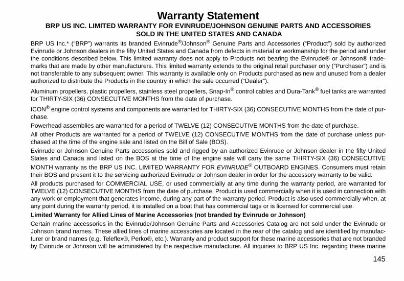
Warranty StatementBRP US INC. LIMITED WARRANTY FOR EVINRUDE/JOHNSON GENUINE PARTS AND ACCESSORIES
SOLD IN THE UNITED STATES AND CANADA BRP US Inc.* (“BRP”) warrants its branded Evinrude®/Johnson® Genuine Parts and Accessories (“Product”) sold by authorizedEvinrude or Johnson dealers in the fifty United States and Canada from defects in material or workmanship for the period and underthe conditions described below. This limited warranty does not apply to Products not bearing the Evinrude® or Johnson® trade-marks that are made by other manufacturers. This limited warranty extends to the original retail purchaser only (“Purchaser”) and isnot transferable to any subsequent owner. This warranty is available only on Products purchased as new and unused from a dealerauthorized to distribute the Products in the country in which the sale occurred (“Dealer”).
Aluminum propellers, plastic propellers, stainless steel propellers, Snap-In® control cables and Dura-Tank® fuel tanks are warrantedfor THIRTY-SIX (36) CONSECUTIVE MONTHS from the date of purchase.
ICON® engine control systems and components are warranted for THIRTY-SIX (36) CONSECUTIVE MONTHS from the date of pur-chase.
Powerhead assemblies are warranted for a period of TWELVE (12) CONSECUTIVE MONTHS from the date of purchase.
All other Products are warranted for a period of TWELVE (12) CONSECUTIVE MONTHS from the date of purchase unless pur-chased at the time of the engine sale and listed on the Bill of Sale (BOS).
Evinrude or Johnson Genuine Parts accessories sold and rigged by an authorized Evinrude or Johnson dealer in the fifty UnitedStates and Canada and listed on the BOS at the time of the engine sale will carry the same THIRTY-SIX (36) CONSECUTIVE
MONTH warranty as the BRP US INC. LIMITED WARRANTY FOR EVINRUDE® OUTBOARD ENGINES. Consumers must retaintheir BOS and present it to the servicing authorized Evinrude or Johnson dealer in order for the accessory warranty to be valid.
All products purchased for COMMERCIAL USE, or used commercially at any time during the warranty period, are warranted forTWELVE (12) CONSECUTIVE MONTHS from the date of purchase. Product is used commercially when it is used in connection withany work or employment that generates income, during any part of the warranty period. Product is also used commercially when, atany point during the warranty period, it is installed on a boat that has commercial tags or is licensed for commercial use.
Limited Warranty for Allied Lines of Marine Accessories (not branded by Evinrude or Johnson)
Certain marine accessories in the Evinrude/Johnson Genuine Parts and Accessories Catalog are not sold under the Evinrude orJohnson brand names. These allied lines of marine accessories are located in the rear of the catalog and are identified by manufac-turer or brand names (e.g. Teleflex®, Perko®, etc.). Warranty and product support for these marine accessories that are not brandedby Evinrude or Johnson will be administered by the respective manufacturer. All inquiries to BRP US Inc. regarding these marine
145
accessories will be directed to the proper manufacturer. To ensure faster and more direct response to warranty and product issuesfor these marine accessories please refer to the enclosed list and contact information. DO NOT return defective items or file a war-ranty claim with BRP US Inc. Warranty Department. Please contact the manufacturer directly. All of the marine accessories soldthrough this catalog come with a warranty established by the manufacturer. Statements of those warranties can be found on thepackaging material packed with the product.
Vintage Parts
Parts identified as Vintage Parts in the catalog and in the BRP US Inc. Master Parts Price Book are not covered by BRP US Inc. Lim-ited Warranty for Evinrude/Johnson Genuine Parts and Accessories. Vintage Parts are sold without warranty, but may be returned incertain circumstances. See the section on returns for conditions on return of Vintage Parts.
The following are not warranted under any circumstances: (a) normal wear and tear; (b) routine maintenance items including, but notlimited to, adjustments, oil changes, water pumps, carburetor maintenance, spark plug replacements, etc.; (c) cosmetic damage orpaint changes due to exposure to the elements; or (d) damage caused by: improper or lack of installation, maintenance, winteriza-tion and/or storage; failure to follow the procedures and recommendations in the Operator’s Guide; removal of parts, improperrepairs, service, maintenance, or modification; use of parts or accessories not manufactured or approved by BRP that are eitherincompatible with Product or adversely affect its operation, performance, or durability; repairs done by anyone, including Purchaser,other than an authorized Dealer; abuse, misuse, abnormal use, neglect, racing, improper operation or operation of Product in a man-ner inconsistent with the Operator’s Guide; external damage, accident, submersion, water ingestion, fire, theft, vandalism or act ofGod; operation with fuels, oils or lubricants not suitable for use with Product (see Operator’s Guide); rust or corrosion; or cooling sys-tem blockage by foreign material.
This warranty will be voided in its entirety and rendered null and void: (a) where Product has been altered or modified in such a wayso as to adversely affect its operation, performance or durability, or has been altered or modified to change its intended use; or (b)where Product is or has been used for racing or any other competitive activity, at any point.
ALL WARRANTIES, EXPRESSED OR IMPLIED, INCLUDING WITHOUT LIMITATION ANY WARRANTY OF MERCHANTABILITYOR FITNESS FOR A PARTICULAR PURPOSE ARE LIMITED IN DURATION TO THE LIFE OF THIS EXPRESS LIMITED WAR-RANTY. ALL INCIDENTAL, CONSEQUENTIAL, DIRECT, INDIRECT OR OTHER DAMAGES OF ANY KIND ARE EXCLUDEDFROM COVERAGE UNDER THIS WARRANTY INCLUDING, BUT NOT LIMITED TO: expense for gasoline, expense for transport-ing Product to and from Dealer, removal of Product from a boat and reinstallation, mechanic’s travel time, in-and-out of watercharges, slip or dock fees, trailering or towing, storage, telephone, cell phone, fax or telegram charges, rental of a like or replace-ment Product or boat during warranty services or down time, taxi, travel, lodging, loss of or damage to personal property, inconve-nience, cost of insurance coverage, loan payments, loss of time, income, revenue, profits, enjoyment or use of Product.
SOME JURISDICTIONS DO NOT ALLOW FOR THE DISCLAIMERS, LIMITATIONS OF INCIDENTAL OR CONSEQUENTIAL
146
DAMAGES OR OTHER EXCLUSIONS IDENTIFIED ABOVE. AS A RESULT, THEY MAY NOT APPLY TO YOU. THIS WARRANTYGIVES YOU SPECIFIC RIGHTS, AND YOU MAY ALSO HAVE OTHER LEGAL RIGHTS THAT MAY VARY FROM JURISDICTIONTO JURISDICTION.
Purchaser must bring the Product, including any defective part therein, and proof of purchase of the Product (original bill of sale) toDealer promptly after the appearance of the defect and, in any event, within the warranty period. Purchaser must sign the repair/work order prior to repair to validate warranty coverage and must provide BRP/Dealer with a reasonable opportunity to repair/replace the defective part. All replaced parts become the property of BRP.
BRP’s obligations under this warranty are limited to, at its sole discretion, repairing or replacing parts of Product found to be defec-tive in material or workmanship, in BRP’s reasonable judgment. Repair or replacement of parts will be without charge for parts andlabor, at any authorized Dealer. No claim of breach of warranty shall be cause for cancellation or rescission of the sale of Product toPurchaser. BRP reserves the right to improve, modify or change Products without assuming any obligation to modify Products previ-ously manufactured. If warranty service is required outside of the fifty United States or Canada, Purchaser will bear responsibility forany additional charges due to local practices and conditions including, but not limited to, freight, insurance, taxes, license fees,import duties, and any financial charges levied by governments, states, territories and agencies.
No distributor, Dealer or any other person is authorized to make any affirmation, representation or warranty regarding Product otherthan those contained in this limited warranty and, if made, shall not be enforceable against BRP. BRP reserves the right to modifythis warranty at any time, being understood that such modification will not alter the warranty conditions applicable to the Productssold while this warranty is in effect.
The Limited Warranty applies only to Products purchased as new and unused from a distributor or dealer authorized to distributeproducts in the country in which the sale occurred. If warranty service is required outside of the country of original sale, Purchaserbears responsibility for any and all charges due to local practices and conditions that exceed or are in addition to customary chargesin the country of sale, such as, but not limited to, freight, insurance, taxes, license fees, import duties, and any financial charges lev-ied by governments, states, territories and agencies.
For assistance, please contact BRP US Inc. Consumer Support, P.O. Box 597, 10101 Science Drive, Sturtevant, WI 53177,1-847-689-7090 or the affiliate of BRP Inc. where the Product was sold to the retail Purchaser or visit www.brp.com.
No other change to the Limited Warranty shall be made or implied. Effective as of July 1, 2011.
* In Canada, products are distributed and serviced by Bombardier Recreational Products Inc.® Registered trademark of Bombardier Recreational Products Inc. or its affiliates.© 2011 BRP US Inc. All rights reserved.Limited Warranty Revision June 2011
147

148
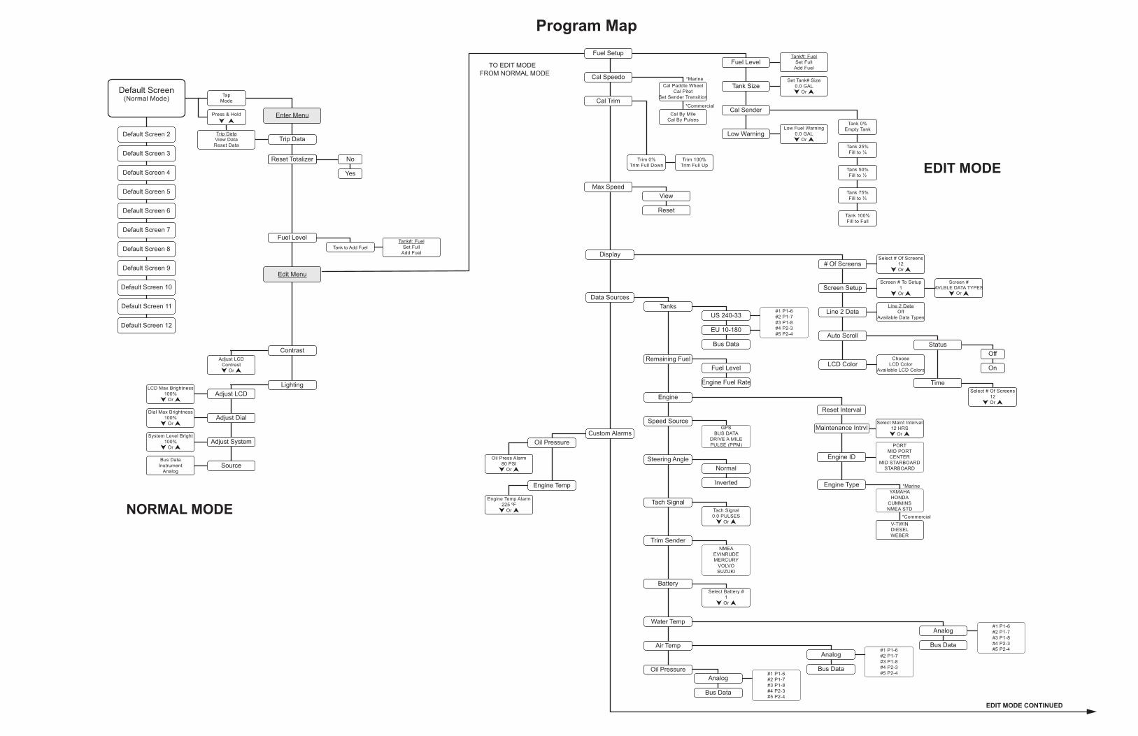
EDIT MODE
NORMAL MODE
Program Map
#1 P1-6#2 P1-7#3 P1-8#4 P2-3#5 P2-4#1 P1-6
#2 P1-7#3 P1-8#4 P2-3#5 P2-4
US 240-33
EU 10-180
Bus Data
Fuel Level
Engine Fuel Rate
Normal
Inverted
#1 P1-6#2 P1-7#3 P1-8#4 P2-3#5 P2-4
Reset Interval
Maintenance Intrvl
Engine ID
Engine Type
No
Yes
Fuel Level
Tank Size
Cal Sender
Tank#: FuelSet Full
Add Fuel
Cal Paddle WheelCal Pitot
Set Sender Transition
*Marine
Cal By MileCal By Pulses
*Commercial
Set Tank# Size0.0 GAL
Or
Low Fuel Warning0.0 GAL
OrLow Warning
Reset Totalizer
Default Screen(Normal Mode) Tap
Mode
Tank 0%Empty Tank
Tank 25%Fill to ¼
Tank 50%Fill to ½
Tank 75%Fill to ¾
Tank 100%Fill to Full
# Of Screens
Screen Setup
Line 2 Data
Screen # To Setup1
Or
Screen #AVLBLE DATA TYPES
Or
Line 2 DataOff
Available Data Types
Auto ScrollStatus
Time
Off
OnChoose
LCD ColorAvailable LCD Colors
LCD Color
Trim 0%Trim Full Down
Trim 100%Trim Full Up
Press & Hold
Trip DataView DataReset Data
Tank#: FuelSet Full
Add Fuel
Enter Menu
Trip Data
Fuel LevelTank to Add Fuel
Adjust LCDContrast
Or
Contrast
LightingAdjust LCD
Adjust Dial
Adjust System
Edit Menu
Custom Alarms
Data Sources
Cal Speedo
Cal Trim
Max Speed
Display
View
Reset
Fuel Setup
LCD Max Brightness100%
Or
Dial Max Brightness100%
Or
System Level Bright100%
Or
SourceBus Data
InstrumentAnalog
Select # Of Screens12Or
Select Maint Interval12 HRS
Or
PORTMID PORTCENTER
MID STARBOARDSTARBOARD
Select # Of Screens12Or
Oil Press Alarm80 PSI
Or
Engine Temp Alarm225 ºF
Or
Tanks
Oil Pressure
Engine Temp
Remaining Fuel
Engine
Speed Source
Steering Angle
Tach SignalTach Signal0.0 PULSES
Or
Trim Sender
BatterySelect Battery #
1Or
Water Temp
Analog
Bus Data
Analog
Bus DataAir Temp
Oil Pressure
NMEAEVINRUDEMERCURY
VOLVOSUZUKI
GPSBUS DATA
DRIVE A MILEPULSE (PPM)
Analog
Bus Data
#1 P1-6#2 P1-7#3 P1-8#4 P2-3#5 P2-4
Default Screen 2
Default Screen 3
Default Screen 4
Default Screen 5
Default Screen 6
Default Screen 7
Default Screen 8
Default Screen 9
Default Screen 10
Default Screen 11
Default Screen 12
V-TWINDIESELWEBER
*MarineYAMAHAHONDA
CUMMINSNMEA STD
*Commercial
TO EDIT MODE
EDIT MODE CONTINUED
FROM NORMAL MODE

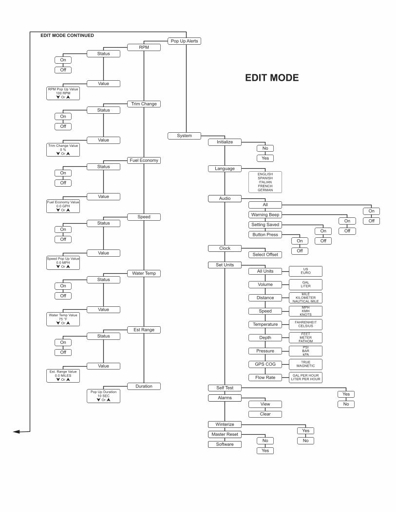
EDIT MODE
All
Warning Beep
Setting Saved
Button Press
ENGLISHSPANISHITALIANFRENCHGERMAN
Initialize
Language
No
Yes
No
Yes
On
Off
On
Off
Yes
No
On
Off
On
Off
On
Off
Yes
No
Audio
Select OffsetClock
All Units USEURO
Volume GALLITER
DistanceMILE
KILOMETERNAUTICAL MILE
SpeedMPHKMH
KNOTS
Temperature FAHRENHEITCELSIUS
DepthFEET
METERFATHOM
PressurePSIBARkPA
GPS COG TRUEMAGNETIC
Flow Rate GAL PER HOURLITER PER HOUR
Set Units
Self Test
AlarmsView
Clear
Winterize
Master Reset
Software
System
Pop Up Alerts
Status
Value
RPM
RPM Pop Up Value100 RPM
Or
On
Off
Status
Value
Trim Change
Trim Change Value0 %Or
On
Off
Status
Value
Fuel Economy
Fuel Economy Value0.0 GPH
Or
On
Off
Status
Value
Speed
Speed Pop Up Value0.0 MPH
Or
On
Off
Status
Value
Water Temp
Water Temp Value75 °F
Or
On
Off
Status
Value
Est Range
Est. Range Value0.0 MILES
Or
DurationPop Up Duration
10 SECOr
EDIT MODE CONTINUED


ICON Pro Series GaugeUser’s Guide
*766075*
ICO
N Pro Series G
auge User’s G
uide P
/N 766075 R
ev A.
Rev A.